
Haptic Actuation Plate for Multi-Layered In-Vehicle Control Panel


1
TAUCHI Research Center, Tampere University, 33100 Tampere, Finland
2
TactoTek Group, 90460 Oulu, Finland
*
Author to whom correspondence should be addressed.
Multimodal Technol. Interact. 2021, 5(5), 25; https://doi.org/10.3390/mti5050025
Submission received: 25 March 2021
/
Revised: 27 April 2021
/
Accepted: 29 April 2021
/
Published: 5 May 2021
(This article belongs to the Special Issue Feature Papers of MTI in 2021)
Abstract
:High-fidelity localized feedback has the potential of providing new and unique levels of interaction with a given device. Achieving this in a cost-effective reproducible manner has been a challenge in modern technology. Past experiments have shown that by using the principles of constructive wave interference introduced by time offsets it is possible to achieve a position of increased vibration displacement at any given location. As new interface form factors increasingly incorporate curved surfaces, we now show that these same techniques can successfully be applied and mechanically coupled with a universal actuation plate.
1. Introduction
The trend for in-vehicle control has been to move from traditional controls with natural tactile feedback to smooth surfaces with capacitive touch interfaces [1]. Buttons or knobs that could once be felt are replaced with a touch sensitive display or surface that often requires a user’s visual attention to interact with. Curiously enough, the technological and constructive advances in ergonomics may often worsen usability by distracting the driver’s attention from the road.
Much of the paradigms that have become a standard in smartphones have simply been moved to in-vehicle displays. An emergence of powerful haptic displays to augment user interaction with in-vehicle infotainment systems has already been shown to decrease task completion time, significantly decreasing distraction while driving, as shown by Farooq et al. in their research [2]. Nevertheless, we believe there is room for further improvement using high-fidelity localized haptics.
Injected molded structural electronics (IMSE) allows for the introduction of in-vehicle control panels that can have varying textures and shapes. This allows for reliable capacitive touch technology to coexist with more defined physical properties. One such interface is the molded in-vehicle control panel, a product designed to demonstrate IMSE features for the automotive industry. Still, this product is missing the active instrumental tactile feedback received from the press or tap of any button location.
A multitude of interaction technologies are being introduced to modern vehicles and used to build multimodal interaction systems for drivers to interact with. It is important to ensure that each component of this multimodal system is responsive to the driver. This includes the tactile interfaces within reach. We see this as an important key technology as it relates to both comfort and safe driving.
By introducing four actuators at key placements beneath the interface arranged over the haptic actuation plate it is possible to reproduce localized precise points of standing-waves vibration interference to enhance the user experience. Rendering a virtual movable actuator keeps manufacturing costs down by reducing the complexity and quantity of components required while enhancing the tactile usability of the in-vehicle interface.
2. Related Work
The concept of high-fidelity haptics as well as its use in expressive haptic feedback have been of well-established concern to researchers, including our team, aiming to enable realistic haptic interaction. In the following sections we briefly review existing works that help support the foundation of our work with the haptic actuation plate presented in this article.
Our previous research has achieved superposition at a much lower frequency using standard voice coil actuators [3]. Allowing for reduced complexity and haptics compatible within the range of feelable frequencies. Experimentation over liquid, gel, and Gorilla glass has helped define the amount of attenuation over different materials [4]. In this case liquid had the least amount of attenuation while gel and Gorilla glass had high levels of attenuation.
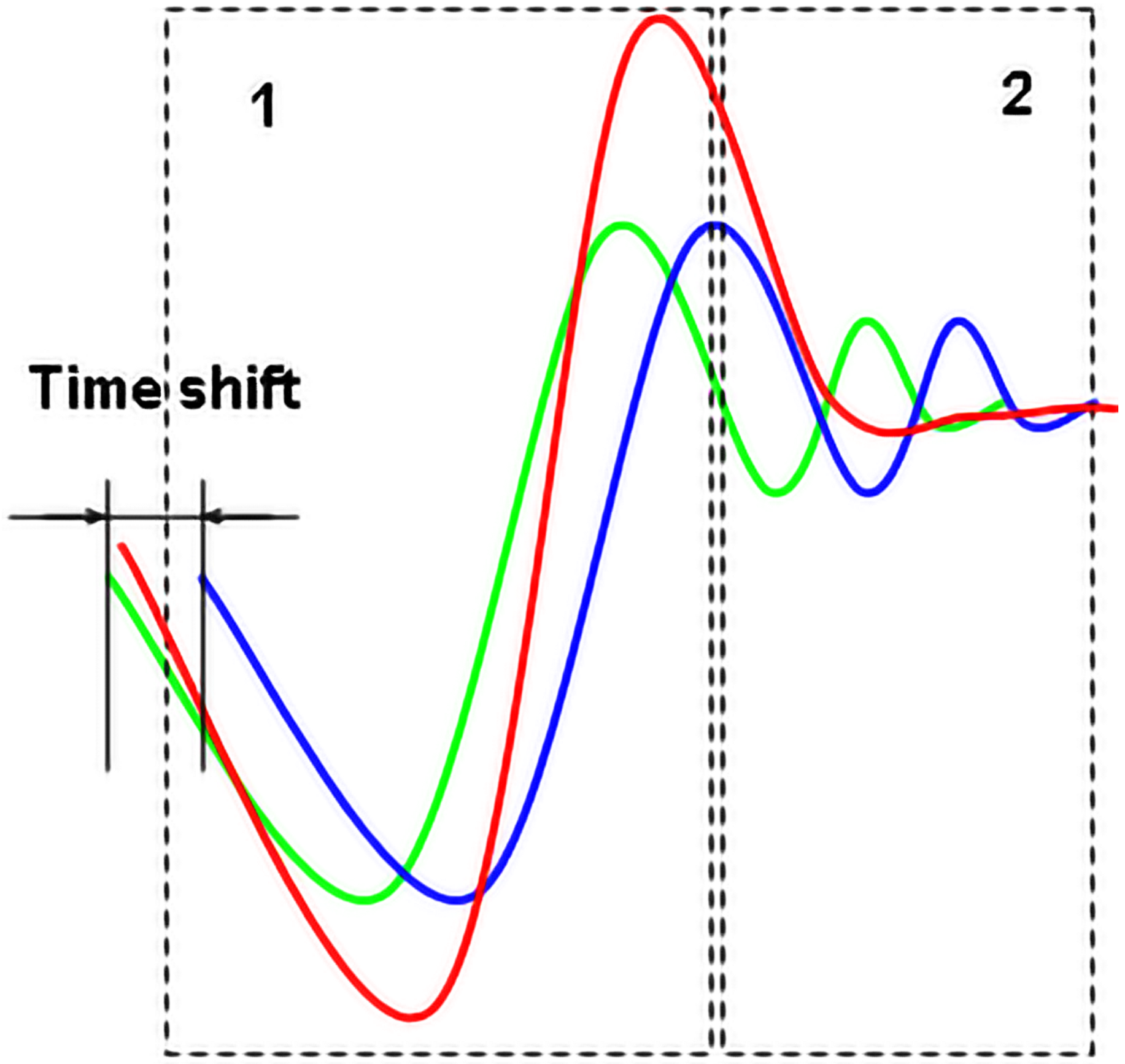
Moreover, the specific offset and configuration of output signals for the actuators arrangement can lead to both constructive interference (1) and destructive superposition (2) of particular components (green and blue) of the composite (red) seismic signal (Figure 1) by diminishing dissipation of the interference maximum.
In addition, we have studied a vibration propagation over curved surfaces and different plastic materials. The results have shown that attenuation can be overcome by increasing the number of actuators affixed to the base actuation plate (thick plexiglass bar) instead of actuators assembled directly with the touch surface of interaction which has a complex outline. This also allows localizing haptic vibrations propagated over a three-dimensional surface attached to haptic actuation plate rather than on a planar touchscreen.
2.1. Expressive Haptic Feedback
To date, designers have worked to enhance the interactivity of onscreen objects through the use of expressive haptic outputs, creating a display where the user can both feel the texture and the geometry of an object being displayed.
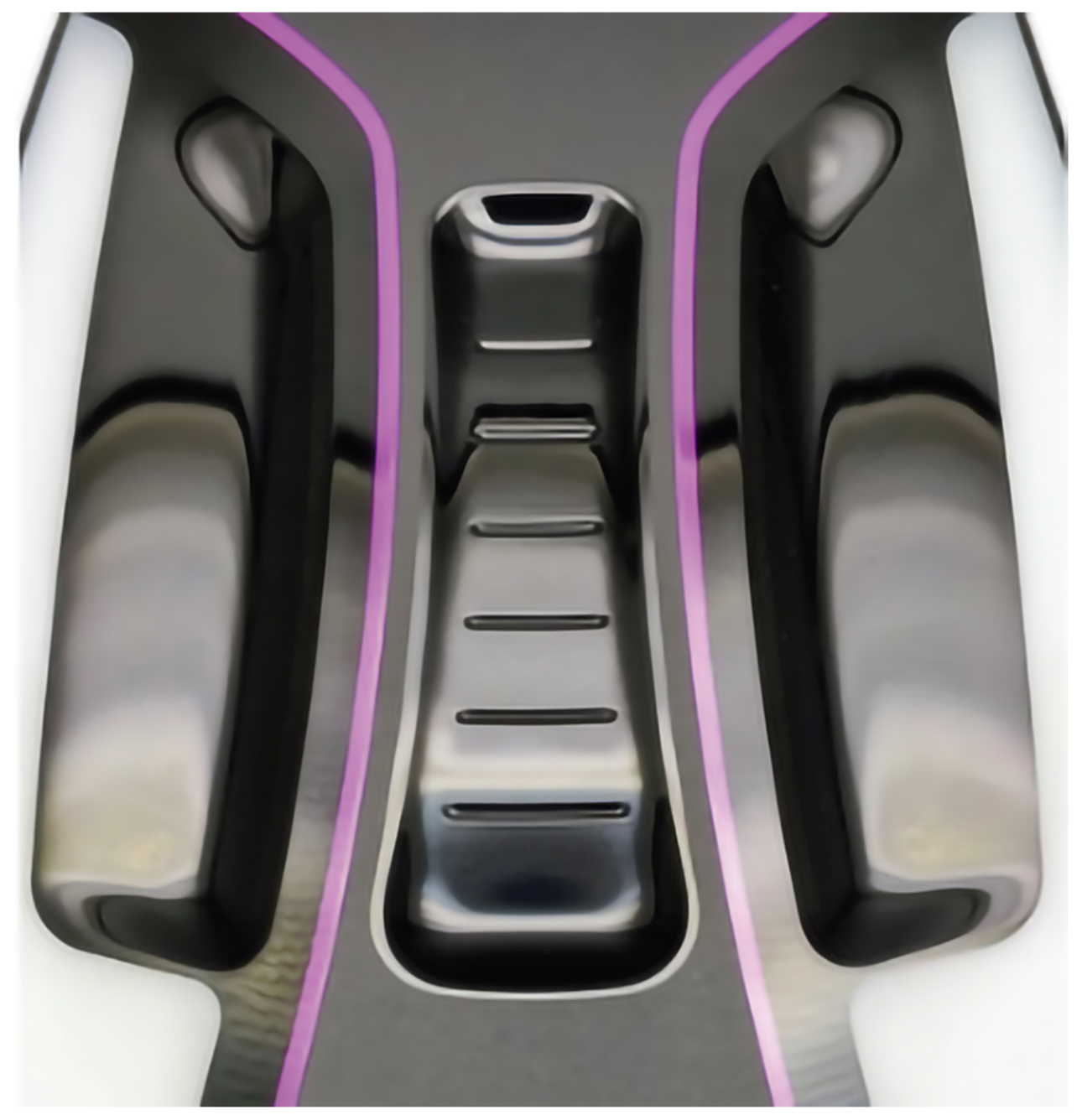
In the absence of visual feedback, touch sensitive input must avoid confusion and prevent incidental activation of undesirable functionality of the control panel. Passive perceptual haptic feedback has been designed and discussed in respective literature [5]. Even the control panel has raised ribs throughout the length of the slider control to provide tactile cues, as illustrated in Figure 2.
Haptic technology advances support development of the non-visual interaction space via enhancement of perceivable tactile information [6]. Still, the challenge is in delivering high-fidelity haptic feedback to detect the exact locations in the absence of visual cues. Advances in actuation and stimulation techniques may lead to the generation of explorable, continuous tactile responses. Both as static and dynamic tactile patterns [7] and vibro-tactile flows [8] of which a user can explore the location of active areas with the slide of their finger [9].
In contrast to typical global vibration produced by the majority of mobile devices, Sato and Tachi [10] have worked on the use of lateral forces to introduce more accurate haptic textures across a display. They have made use of motors pulling strings along the outer edge of a tablet in order to produce lateral vibrations. Initial recordings of vibration profiles were created using an accelerometer attached to a finger passing over a given material such as sandpaper. Later, these recordings were used to create the necessary lateral vibrations used to emulate specific textures over a tablet display.
The use of advanced haptic vibration techniques was shown by Martinez et al. in [7] who found that incidental learning can facilitate categorization in distinguishing dynamic tactile patterns through a visuomotor task. Rather than a simple temporal vibration, the researchers used a simulated offset vibrotactile movement provided to users in order of decreasing reaction time to choose alternative images of a star and circle. Each direction of vibration movement was associated with a respective symbol, taking advantage of user’s ability of incidental learning. This incidental learning is important in any scenario where touch is a primary input into a device, especially when vision is occupied by another task.
With the introduction of flexible displays new methods of interaction are being developed for mobile phones. Apple, for example, has been granted a patent for a flexible edge display which would replace typical tactile buttons found on the side of the phone. As the screen on the edge of the phone may not always be clearly visible, the introduction of new haptic techniques might be used to enhance the usability of such interface [8,9].
2.2. High-Fidelity HAPTICS
High-fidelity haptics refers to feedback that is felt accurately at a specific location, rather than the conventional global vibration felt, for example, from a typical mobile phone. In practice, high-fidelity haptics can be achieved using an array of actuators. Each actuator can be placed at the point where the actuation is intended to be felt. Velko Vechev [11] and their team have worked with creating small form factor haptic feedback electromagnetic actuators placed on a glove that create tactile stimulation directly to the user hand. For the most part this is the regular way most of the researchers are currently using to create high-fidelity haptics relying on different type of actuators including electrotactile stimulation [12], pin-based mechanical vibrators [13,14,15] and linear motors [14,16,17].
In this regard, the selective displacement of a two-dimensional array of long pins, which moves through an apertured plate to different positions has been already studied in a number of trials [7,14,15,17,18,19]. Although many technological approaches have been applied in order to control the specific parameters of individual tactile pixels (taxels), it was proven that such a way of rendering detailed haptic textures has disadvantages [13,14,20,21]. Volumetric shape displays using the bed-of-pins approach remain limited by their 2.5-dimensional nature as well as their large scale due to the size and quantity of the actuators in use [13].
Skin that is stimulated directly by two vibrotactile actuators reproduces a single sensation that is perceived in between the points of stimulation [8,22,23,24]. By modifying either the intensity or the time offset of the applied stimulus, the location of the perceived position can be moved. However, when vibrations are transmitted to the hand through a rigid multilayered medium such as the in-vehicle control panel, the perception of a stimulus that is not present at the point of contact (i.e., static phantom sensations [25]) is difficult to induce properly at an assigned specific place of operating area due to its curved outline.
As known from studies and scientific literature, vibration localization using multiple actuators is possible to some extent (e.g., by placing actuators at four locations) with the introduction of impractical external dampers [26]. Due to the practical limitation these approaches have, research has shifted direction from positional information rendering to directional information rendering such as that of vibrotactile flows. In which case high-fidelity vibration localization is not necessary.
In the search for different methods and techniques to achieve localized haptics, the use of infrared light has been experimented with to activate a PET film coated in a membrane reactive to light [27]. By passing infrared light at a specified location a localized vibration can be activated. Thus, potentially leading to localization that is only limited by the resolution of the light source. Although the use of infrared light sources are commonly used in hand tracking with larger projection displays, it would be yet to be seen how the application of a near infrared light source might be integrated into smaller handheld display technology, or within the layered structures of injected molded electronics.
The use of a thermoactivated gel has also been explored in the past [28]. By applying heat to a poly gel layer via resistive heating elements the area that is heated becomes stiff to the touch. This gel becomes visibly opaque as it is heated, altering the visibility to the target location. Although the effect is well defined by touch, the process of heating the gel, as well as waiting for the gel to cool takes a significant amount of time. The limited refresh rate of the actuation component, as well as the energy required for resistive heating limits this designs practical use cases.
The MudPad shows us a different take on the well tested array of pins approach [29,30]. Rather than use actuators to physically move individual pins to create localized feedback, an array of electromagnets is used to actuate a layer filled with a magnetorheological fluid. This allows for similar precision as the pin array approaches, while keeping a smaller footprint similar in size to the actuated overlay. The Magnetorheological fluid is opaque and operates directly through the pouch it is contained within. Changing individual electromagnets magnetic fields allows for precision changes in not only localization, but stiffness of the material.
Similar work exploring magnetorheological fluid has been conducted but without a dry surface layer [31]. Participants interacting directly with their hands submerged with the magnetorheological fluid were able to actively interact with similar localization achieved within the liquid. These methods, similarly, to other pin arrays, rely on individual components at the point of localization. In these fluid examples the liquid itself acts as an actuator in combination with the underlying electromagnet.
A vibrotactile flow provides a continuously moving sensation across the surface of a device, providing a sense of direction. Implementation of vibrotactile flows can be achieved using only two actuators, rather than an actuator array. This is done by controlling the constructive interference of vibration signals coming to the necessary point of skin contact.
It has been shown that by using multiple actuators, communication through touch can be enhanced over existing vibration motors. Seo and Choi showed that by placing four Linear Resonant Actuators (LRAs) positioned at each corner of the device and actuating them at predetermined offset timings, rotational feedback can be communicated to a user through the edge of a device [8]. Users in their experiment could feel the directional flow of a given actuation as it traveled around the device.
In closer relation to our current work, Enferad et al. [32] have worked with the generation of controlled localized stimulation over a haptic display. This has been achieved by installing a row of piezoelectric patches over a staple shaped aluminum beam.
Superposition had occurred within the beam along a single access. To achieve the assigned point of superposition, the output of assembly of piezoelectric actuators was configured primarily using voltage phase modulation.
Another accurate method employed to achieve localized haptic feedback is the implementation of time-reversal wave focusing. Charles Hudin and their team designed a tactile display with an array of 32 actuators bonded to the underside periphery of a glass plate [33]. A vibrometer was used for to accomplish calibration of the time-reversed wave during the focusing stage. The goal of this research was the development of a very precise localized point of tactile feedback. However, known so far experimental haptic techniques (based on a close-loop control) for high-fidelity signal localization [20,34] raise significant difficulties and limitations in its practical implementation in mobile devices even on a flat interaction surface.
3. Materials and Methods
We have been provided with a universal in-vehicle touch sensitive control panel (demonstrator) assembled based on IMSE technology. The control panel itself is not designed to any specific regulatory requirements. Instead, it follows interior parts industry standards to demonstrate the versatility of IMSE configuration and fabrication.
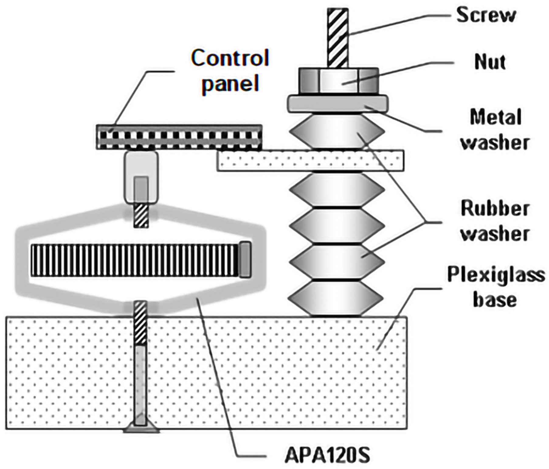
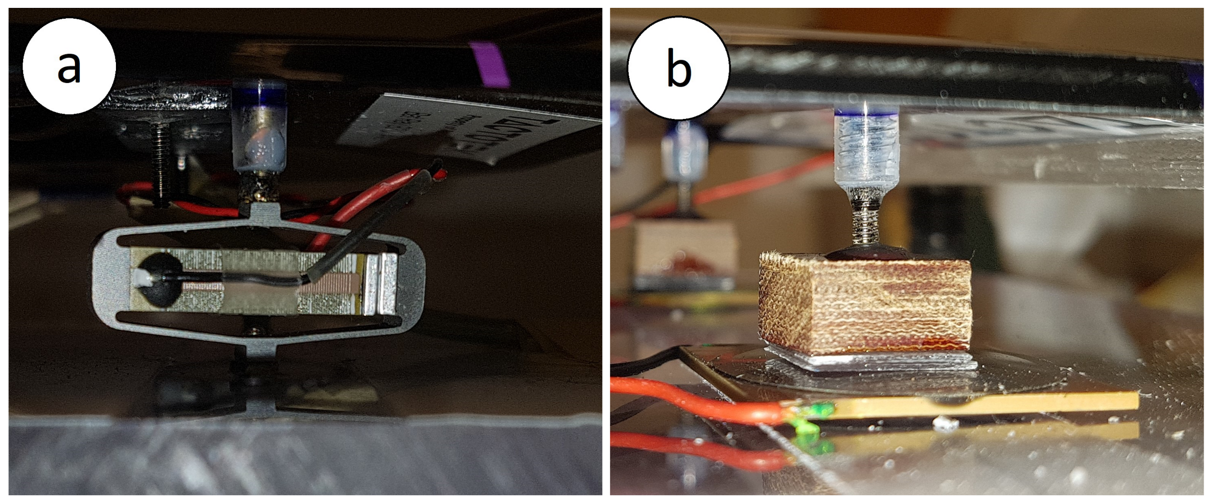
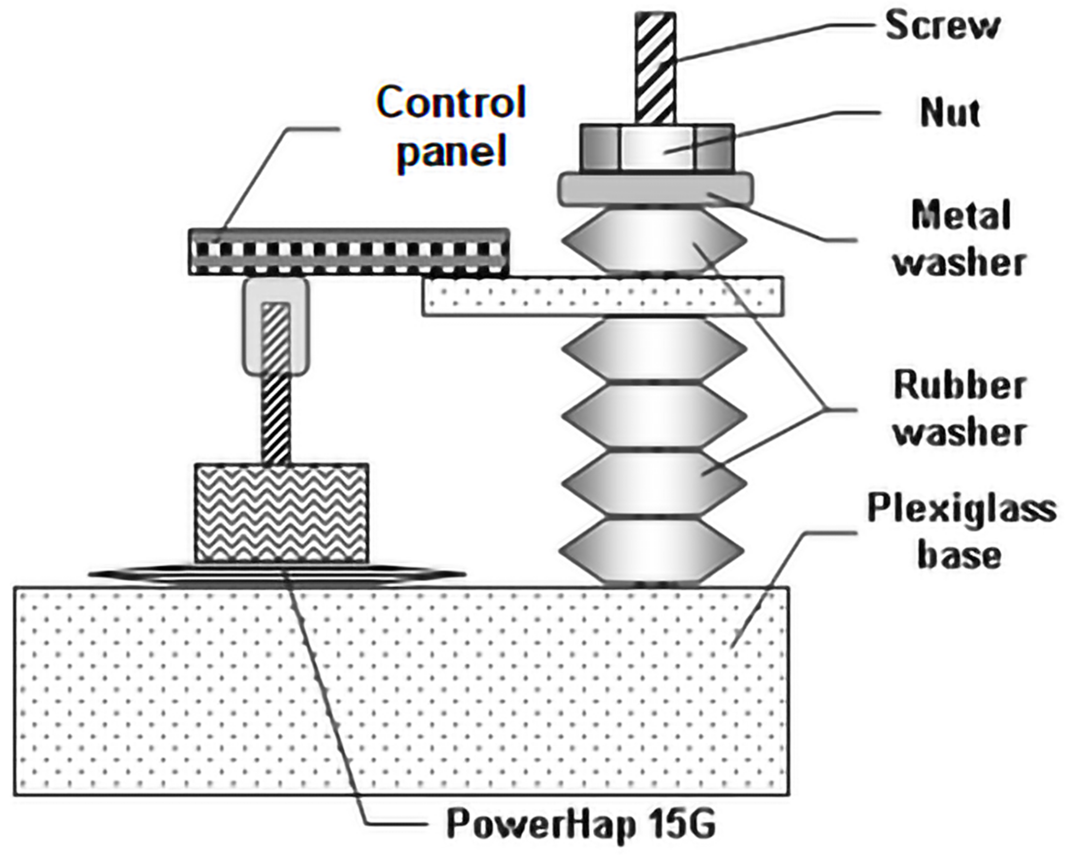
Two equal control panels (demonstrators) have been affixed to a thick plexiglass base (haptic actuation plate) with a possibility of vibration in orthogonal direction (Figure 3 and Figure 4) using APA120S amplified piezoelectric actuators from Cedrat Technologies (Figure 3 and Figure 4, to the left) and TDK PowerHap 15G (Figure 4 and Figure 5, to the right). APA120S actuators are described as a mechanically magnified preloaded stack of low voltage piezoelectric ceramics [20] (PZT type). This technology allows for the attachment of the actuators without the need of additional tensioning. The actuators are affixed directly with screws to a plexiglass actuation base (haptic actuation plate) and with screw posts to the four mounting points found underneath the interface. No other attachment or adjustment is required. Besides obvious benefits, the much higher cost of the APA120S puts it at a disadvantage for consumer production. Nevertheless, the APA120S actuators are easy install and to work with. The APA120S also operates at a very wide response rate; from 0 to 100 kHz. This means we can reproduce as close as possible the necessary components of the signal configuration adapted immediately for both constructive interference (1) and destructive superposition (2), as shown in Figure 1, yet in a feelable range of vibrations. For this reason, we have chosen to work with the APA120S actuator for our initial testing.
Our preliminary design expands on existing research demonstrating the successful creation of a virtual vibration source across different configuration of deformable surfaces [3]. We expect the control panel may behave differently due to its multi-depth curved shape and multi-layered structure. We have chosen this project to apply advance haptic techniques to the emerging technology of touch panels.
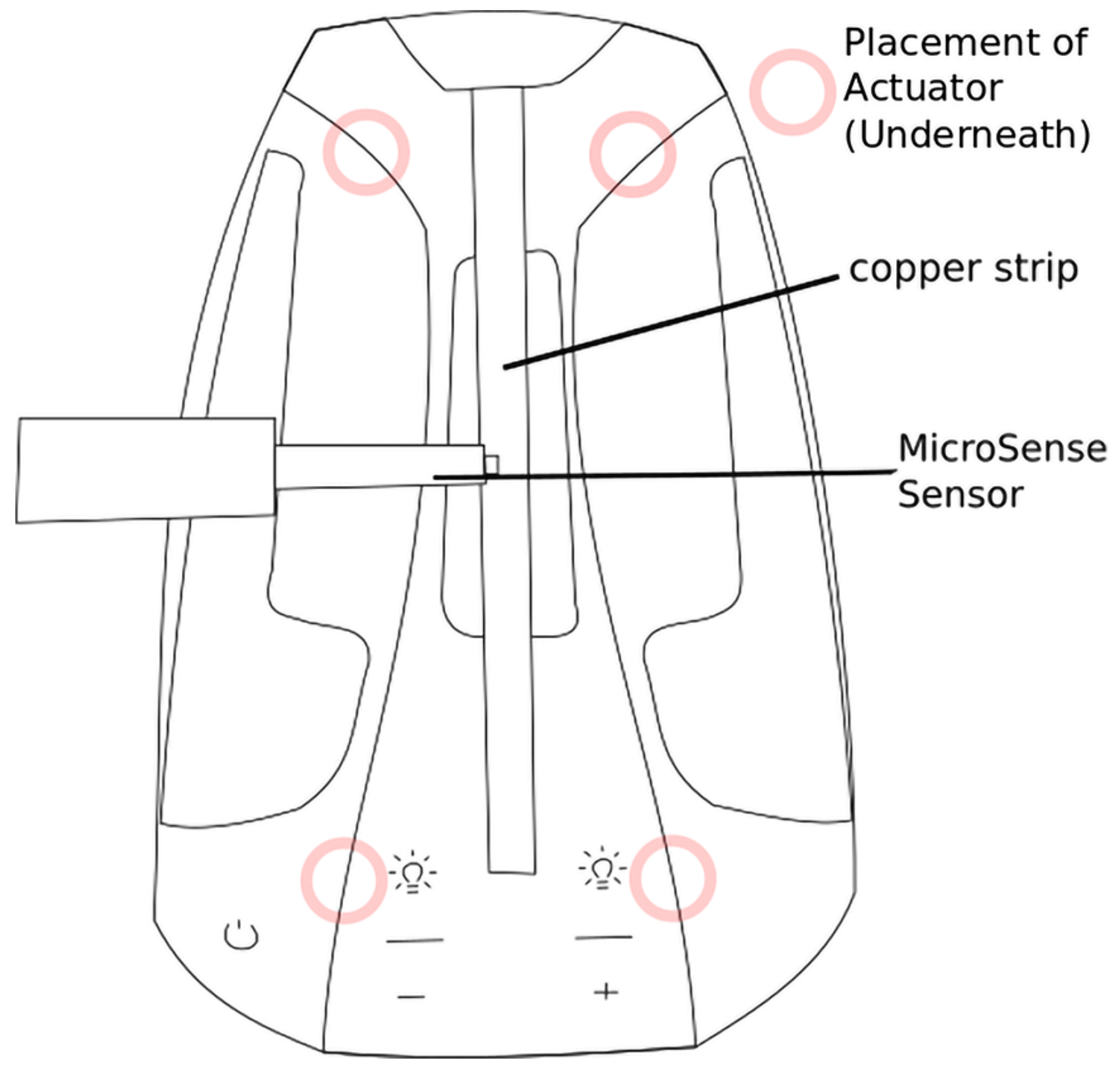
Alternatively, to apply actuation force to the control panel we have chosen to use a TDK PowerHap 15G piezoelectric haptic actuator. We have chosen the PowerHap 15G due to its compact size, planar form-factor, cost and efficiency. These factors suggest that this type of haptic actuators is suitable to be further embedded into a product. TDK also produces more powerful PowerHap amplified actuators such as the 6005H090V120 and similar, smaller size 1204H018V060. Their constructive features do not always allow as easy installation as the APA120S which have built-in threaded holes. Nevertheless, the PowerHap 15G piezoelectric actuator is designed with haptics in mind with suggested applications including automotive displays. The actuators are driven by an amplifier designed to output the required high voltage (120 V) specified. The initial signal to control our driver is output from an Arduino Due microcontroller board. The Arduino Due operates on an 84 MHz clock, allowing for microsecond precision for generating haptic signals. The PowerHap 15G actuators were placed at key location as shown in Figure 6.
The goal of the presented research was to produce localized high-fidelity haptic vibrations at the specific locations along the central slider of the control panel and other locations requiring active response to human touch. Now, due to the integrated molded circuit design of the control panels it was not readily possible to integrate components within the interface after manufacturing. For this reason, the actuators have been placed directly with a thin adhesive tape (as recommended in the PowerHap 15G Documentation [35]) or the proper screws to the haptic actuation plate (plexiglass base) that lays beneath the control panel interface. Existing screw mounts in the interface were used as the points of application tangential force (10–26 N) from actuators. A metallic screw post was screwed into a small thick fiberglass block and its other end inserted up to the stop into plastic mounting points of the control panel (Figure 4 and Figure 5). The fiberglass block is then affixed directly to the top of the actuator to provide the vibration transfer point to the surface of the interface. To provide the necessary preload tension (10 N) required by the PowerHap 15G actuators, fixation of the control panel in relation to the haptic actuation plate was designed with adjustable level of elevation (20 ± 3 mm). In practice, the PowerHap 15G should be embedded within the molded interface in specific locations providing the required preload during the manufacturing stage.
Due to the concave design of the central slider of the control panel it was not possible to measure the concave slider’s surface directly using the planar rectangular MicroSense sensor in our data gathering (Model 5622-LR Probe, with 0.5 mm × 2.5 mm sensor). Instead, it has been temporary filled in with Blu Tack adhesive resin and covered with an adhesive cooper strip.
The sensor has an accuracy of 0–200 um with noise of 3.44 um-rms @5 kHz amplified with gauging electronics until 10 V and attenuated to a range of 0 to 5 V to be compatible with the Arduino’s analogous input. The depth of the concavity is minimal at around 2 mm. We believe any influence on final measurements to be minimal.
The signals applied to haptic exciters used in both set-ups are identical. Both types of piezoelectric actuators have two stages of duty cycle. Actuators are charged by applying positive control voltage that affects their expansion on the order of 0.1% to 0.2% of the piezo stack length. Then actuators are discharged that allows contracting them due to external load or surrounding flexure-shell. For simplicity, we are using a single charged and then discharged group of pulses.
It follows to note that, though both types of piezoelectric actuators excited by a positive voltage polarity lead to an extension in thickness of multilayered piezoelectric crystals, Cedrat amplified technology uses a stainless steel shell in which the piezoelectric stack is placed along the long axis (28.7 mm), while vibration magnitude is proportional to the short axis (13.0 mm) in inverse direction. That is, mechanical amplification is about twofold greater than the actual stroke of piezoelectric stack. However, the resulting displacements of the control panels excited with PowerHap 15G and APA120S actuators happened in antiphase which we will consider when present in the data recorded during vibration propagation over demonstrators.
4. Results
Although four actuators were used for the final output, the initial offsets were found by testing actuators in pairs. One actuator was marked as the point of reference. We can sweep through a range of offsets for each actuator pair. For example, we can gather vibration data for actuation off sets gathered from the top left and bottom right actuator. We can then do the same with the top left and top right actuator.
From the data gathered from this range of time offsets, the offset for each actuator pair determined to create peak interference can be combined and used to trigger all the actuators in relation to the top left actuator. Our previous work with curved surfaces has shown that a near maximum peak may be produced with this method without the time consumption of going through every offset combination required if we were to scan through all four offsets simultaneously [36].
In order to find the offsets required for maximum constructive wave interference, a range of offset signals were measured at a given point using the MicroSense sensor. For each set-up, measurements have been done at 10 mm step increments starting from the bottom of the interface slider to the top of the slider (Figure 7). Each 10 mm step measurement has been recorded at 1 ms intervals for an offset ranging from 0 to 3 ms before and after triggering the first actuator.
The measurements consist of the MicroSense data during the offset as well as after the second vibration signal is triggered. This recorded data measured the peak-to-peak voltage of the control panel response to each offset of actuation signals. After collecting the data of the offset sweep, the offset with the largest peak-to-peak maximum was where the Arduino was able to record the largest range in vibration magnitude, and where constructive wave interference occurred.
Similar research [3] with the MicroSense sensor has determined by making a superposition of five measurements at a single point that there was a negligible amount of variability between measurements. This means we can expect that our results should be stable and reproducible.
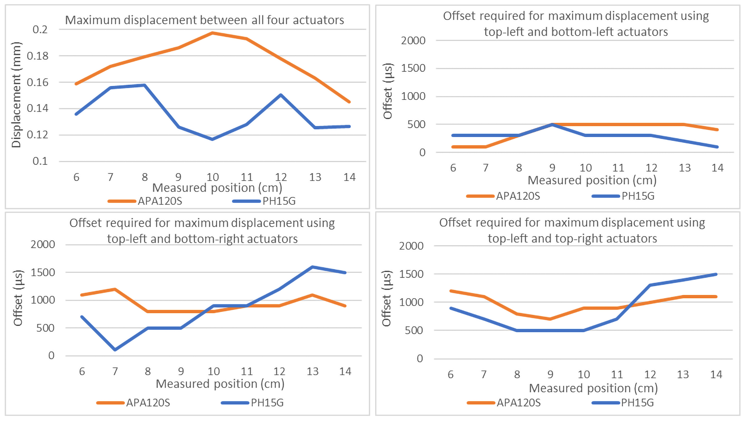
The results in Figure 8 illustrate the required offsets between a given two actuators to create maximum vibration displacement. Actuation always took place in reference to the top-left actuator. The results of the PowerHap 15G have revealed that between the top-left and bottom-left actuator there was a clear change in offsets required at different points of the surface. The data for the top-left and top-right actuation have demonstrated a similar pattern of the control panel response over a narrower offset range. This is likely due to the parallel positioning of the actuators in reference to the central location of the measuring strip. For the Top-left and Bottom-Left actuation we have detected a much flatter graph. These actuators are placed orthogonally to the targeted central location of the measuring strip. This means that as the measurement position changes, we cannot discover a change of offsets because the measurements over the position is always equally distant from each of the two actuators.
At first, we can notice that the APA120S provides a larger amount of displacement across the surface of the slider. This is due to the larger amount of energy required to actuate the APA120S at a given voltage (Table 1). The results collected of the offsets required to achieve maximum displacement at any given point with the APA120S actuators indicate a much more narrow and flatter result. Although there are noticeable and consistent offset maximums, the distinctions between offsets are not as pronounced as with the PowerHap 15G actuators. We believe this is in part because of the way the APA120S operates. In Table 1, it is shown that while the PowerHap 15G actuator is placed under a 10 N preload, it is virtually nonexistent for the APA120S. This means that while vibration interference still exists as illustrated in Figure 8, the lack of preloading alters the method of impact, likely reducing its effectivity achieving precise wave interference across the control panel interface.
The offsets found for each actuator pair were combined for each point of interest across the surface. The results are shown in Figure 8. Ideally, we would hope to reveal a flat line indicating equal maximum interference at any given point. This might be the case if using a more compatible elastic material. In this case we are using a hybrid modeled material in which a certain amount of attenuation is to be expected.
With the PowerHap 15G actuators we achieved lower points of maximum interference near the center where distance from the four actuators would be equal. Such a result might be observed due to attenuation as the vibration travels through the model multilayered material. Fortunately, at this distance the attenuation in maximum displacement is quite low with a difference between peaks of 9.7 dB. It also has been observed that as the measurement was made closer to the actuators the maximum vibration increased as expected with a difference between peaks of 9.7 dB.
The results of the use of the APA120S actuators demonstrated an overall larger displacement with a gradual increase as measurements moved to the center of the central strip. In some manner the APA120S actuators placed in this configuration in combination can surpass the threshold for loss due to attenuation. This is likely due to difference in construction between the APA120S and PowerHap 15G actuators. The PowerHap 15G is preloaded and expands outward in an orthogonal placement, returning to its non-loaded state.
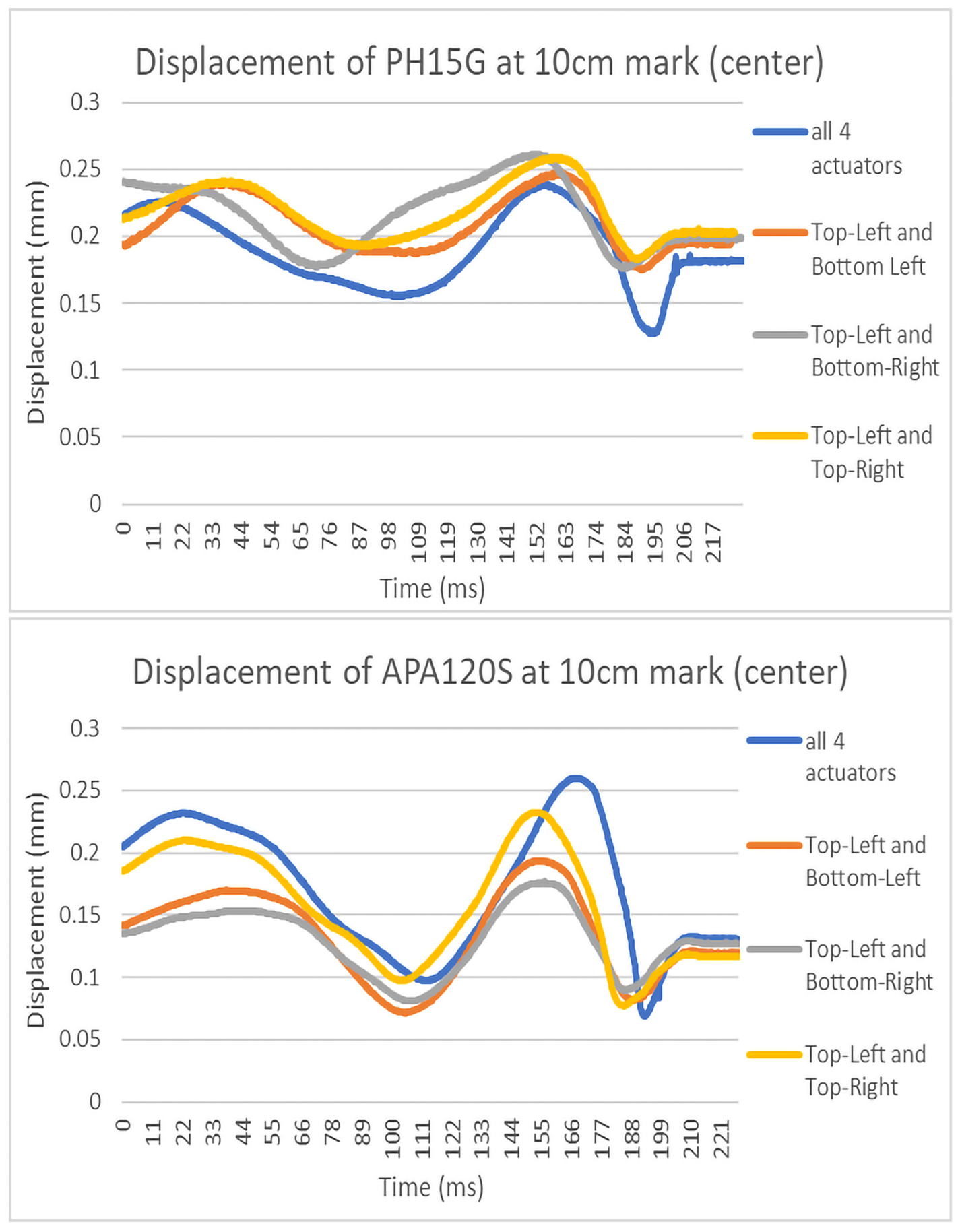
Figure 9 is a sample of the constructive waves measured at the center of the slider. Each found offset maximum between actuator pairs is shown, as well as the resulting combination of offsets. As it was demonstrated with the PowerHap 15G actuator, the final negative downward displacement at the end of the wave is magnified several times. Although we have detected an increase in displacement magnitude when actuating all four APA120S actuators, the increase is nowhere near as pronounced. As it can be observed in Figure 8, the offsets found to produce peak displacement for the APA120S do not change much in any of the graphs, implying that localized feedback has not been produced in this case.
On the contrary, the data collected with PowerHap 15G revealed that the Offsets required to reach maximum peak between the actuators located at the top left and bottom left of the control panel demonstrated a linear trend that can be found between measurement points indicating a high confidence that localization was achieved. The Top-left and top-right actuators are located parallel to the slider. As expected, we also see a more shallow but rising trend as the distance between points and the actuation does not vary as much as the previous measurements demonstrated.
Finally, the graph for the top-left and bottom-left actuations has very little change as the MicroSense sensor moved across the slider. The reason for this phenomenon is that the actuators are placed in orthogonal direction from each other in reference to the central slider. This means that as the sensor moved across the slider, it was always measuring a point that is proportionally the same distance from each actuator.
5. Discussion
As manufacturing techniques continually improve and allow for user interface technology to take on a continuing variety of shapes and form-factors, engineers and technologists will need to rethink the ways of providing user feedback. Displays are beginning to no longer conform to the shape of a flat rectangle [37,38]. Flexible phones may have at times portions of their display out of a user’s view. Physical buttons are continually being swapped out for cheaper, more reliable IR and capacitive sensor-based interfaces [39,40]. Any solution that brings haptic feedback to consumer devices will need to be simple to integrate, reliable, and low cost.
Vehicles today are incorporating multimodal interfaces to give drivers a variety of methods to communicate with and control different aspects of their driving experience [41]. For a multimodal system to effectively work, each input modality must be as effective and easy to use to be a viable choice to the driver. For example, if a speech recognition fails to recognize a driver’s voice repeatedly, then the driver will begin to avoid using this modality to the point that it may as well not be available as an option. This can also be said about a touch panel such as the one we are working with. If a driver has difficulty in interacting with a tactile interface due to the lack of tactile feedback, they may avoid using it. Often the goal with a multimodal interface is to reduce a driver’s stress levels or cognitive load, leading to safer driving [42]. Therefore, each input in the overall system needs careful attention to detail so that a driver can choose the most comfortable interaction technique for the given situation.
Our exploration demonstrates that existing research [3,4] over flat surfaces can be translated to an object with varying depth and curvature. We are continuing to find that once offsets are found and set, the resulting output stays remarkably consistent. Sustainability is important, as localization offsets only need to be gathered once for a given device configuration. What we have also learned is that losses due to attenuation can be compensated for using additional actuators.
The empirical findings in this paper suggest that the PowerHap 15G is the superior actuator when achieving a virtual actuation point at a given area across the interface. An additional advantage of the PowerHap 15G is its flat planar form-factor. Because of its small footprint it can be easily integrated into existing printed circuit board assembly (PCBA). Piezoelectric actuators are known for their reliability and long life, ideal for implementation in products with fewer serviceability options while still expected to have a long life [43]. The simple design of the actuator also allows for easy implementation in existing circuit designs. Moving towards simplified circuit design with standard components moves us closer to the possible ubiquity of high-fidelity haptics across a multitude of consumer products.
There is also some scientific literature that refers to the touch enhancing properties of intermediate materials. For instance, cellophane film is already in use by body shop mechanics to examine the quality of polishing on vehicles [12]. Furthermore, the Touch Enhancing Pad [15] is a patent that describes a pad composed of a small amount of lubricant enclosed within two plastic sheets effectively enhancing touch in applications such as the detection of tumors in breast tissue.
A variety of materials have been tested in other research [4] finding that differing materials affect the performance of the resulting virtual actuator. For any given device, changing the material covering substantially is not always an option. Therefore, it would be interesting to study if a material structure can be introduced as an additional active layer underneath or over the existing product further modifying and enhancing the magnitude as well as the tactile perception of the virtual actuator vibration.
Ideally, we would like to demonstrate the flexibility and portability of this offset actuation method. The actuation plate used in this research was built with the idea that it can be attached to any form-factor device to make a step forward from a primitive actuation technique to high-fidelity haptics able to provide a vision-free navigation in 3D haptic space.
In related research [3,4] the offsets that have been found and are used to create localized vibration focal points are triggered within milliseconds in the single digits. This may mean that quick rapid changes in the offset actuation could allow for multiple focal points that are perceptually simultaneous. If this is possible, we then open the possibility to create perceivable detailed haptic images. The possibility to communicate contour graphics over a surface adds a form of additional bandwidth that can bring clarity to haptic feedback. The handles of a video game controller, or the back of a phone are both areas that at times have large areas of the hand over them, areas that could benefit from the introduction of high-fidelity haptic feedback.
We would like to further explore the offset actuation technique implemented in objects with more pronounced curvature, such as that of a sphere [36]. A curved surface introduces points of localization that are both normal and tangential to the actuator. We expect this to introduce vertex forces that will alter a user’s perception of localization. As many user interfaces consist of areas of large curvature, such as a mouse or gamepad, it is important for us to understand how the method for virtual actuation can be implemented in such an application for in-vehicle use.
We can imagine that any surface that contacts a driver can be used to communicate with said driver. This could extend to the steering wheel, the head restraint, or the seat itself. Localized vibrations at any of these points could potentially be used to communicate all manner of information. For example, the location of a vibration on a seat could aid with lane assist or collision avoidance technologies. Localized vibrations across a steering wheel could help a driver navigate through a city by providing cues as to when and where to turn.
Beyond the use of in-car navigation, high-fidelity haptics has a plethora of possible uses. Accurate haptics could provide further immersion ual reality environments, communicate detailed touch communication over long distances, or enhance feedback on touchscreen keyboards found on tablet displays.
In the future, user testing would be required in order to get a better understanding of the driver’s ability to distinguish tactile patterns of control panel based on constructive wave interference of vibration haptic signals in the absence of visual feedback. It is important to understand a user’s experience with virtual actuators. An operating vehicle introduces ambient vibrations as well as visual distractions that will likely affect a user’s interaction with the control panel [2,44]. That being said, classic tactile buttons on a dashboard can be felt quite easily in normal driving situations which would lead us to believe it is possible to differentiate artificially created haptic responses from ambient vibrations. Meanwhile, we are working together with the engineers of the control panel to integrate TDK PowerHap15G actuators into technological pockets underneath the control panel.
6. Conclusions
We have shown that offset actuators can be used to create points of peak vibration across a curved multilayered surface such as that of the demonstrated control panel for in car installation. For this application, we believe that use of such actuation techniques to improve haptic feedback across the touch sensitive interface can help a user better focus on driving. The TDK PowerHap 15G had superior performance in relation to vibration localization for this application. It has a flat, small footprint that provides a more accurate virtual tactile point than could be achieved by the Cedrat APA120S actuators. The TDK PowerHap 15G is also significantly cheaper than the Cedrat APA120S.
This work expands on existing previous research and demonstrates that the use of a virtual vibration point can be achieved over nonstandard molded layered structures. This would allow for the use of fewer actuators in a variety of feedback interfaces when creating high-fidelity haptics.
Author Contributions
Conceptualization, P.C., G.E., and R.R.; methodology, G.E.; software, P.C.; validation, P.C.; formal analysis, P.C. and G.E.; investigation, P.C. and G.E.; resources, H.S. and A.H.; data curation, P.C. and G.E.; writing—original draft preparation, P.C.; writing—review and editing, P.C., G.E., and R.R.; visualization, P.C. and G.E.; supervision, G.E. and R.R.; project administration, R.R.; funding acquisition, R.R. and A.H. All authors have read and agreed to the published version of the manuscript.
Funding
This work was supported by project Multimodal In-Vehicle Interaction and Intelligent Information Presentation (MIVI), funded by Business Finland (grant 8004/31/2018). The control panel has been provided for testing by the TactoTek Group.
Institutional Review Board Statement
Not applicable.
Informed Consent Statement
Not applicable.
Conflicts of Interest
The authors declare no conflict of interest.
References
- Jinquan, L.; Shengjie, Y.; Zhou, Y. Automotive Display Trend and Tianma’s Directions. In Proceedings of the 2019 26th International Workshop on Active-Matrix Flatpanel Displays and Devices (AM-FPD), Kyoto, Japan, 2–5 July 2019; pp. 1–4. [Google Scholar] [CrossRef]
- Farooq, A.; Evreinov, G.; Raisamo, R. Reducing driver distraction by improving secondary task performance through multimodal touchscreen interaction. SN Appl. Sci. 2019, 1. [Google Scholar] [CrossRef] [Green Version]
- Coe, P.; Farooq, A.; Evreinov, G.; Raisamo, R. Generating Virtual Tactile Exciter for HD Haptics: A Tectonic Actuators’ Case Study. In Proceedings of the 2019 IEEE SENSORS, Montreal, QC, Canada, 27–30 October 2019; pp. 1–4. [Google Scholar] [CrossRef] [Green Version]
- Coe, P.; Evreinov, G.; Raisamo, R. Gel-Based Haptic Mediator for High-Definition Tactile Communication; Association for Computing Machinery: New York, NY, USA, 2019; pp. 7–9. [Google Scholar] [CrossRef]
- Evreinov, G.; Raisamo, R. Information kiosks for all: Issues of tactile access. Proc. WWDU 2002, 2002, 399–401. [Google Scholar]
- Quinn, P.; Lee, S.; Barnhart, M.; Zhai, S. Active Edge: Designing Squeeze Gestures for the Google Pixel 2. In Proceedings of the 2019 CHI Conference on Human Factors in Computing Systems, Glasgow, UK, 2 May 2019; pp. 1–13. [Google Scholar] [CrossRef] [Green Version]
- Martinez, J.; Holt, L.; Reed, C.; Tan, H. Incidental Categorization of Vibrotactile Stimuli. IEEE Trans. Haptics 2020, 13, 73–79. [Google Scholar] [CrossRef] [PubMed]
- Seo, J.; Choi, S. Edge flows: Improving information transmission in mobile devices using two-dimensional vibrotactile flows. In Proceedings of the 2015 IEEE World Haptics Conference (WHC), Evanston, IL, USA, 22–26 June 2015; pp. 25–30. [Google Scholar] [CrossRef]
- Myers, S.A.; Lynch, S.B.; Montevirgen, A.S. Electronic Devices with Sidewall Displays. U.S. Patent 8,723,824, 13 May 2014. [Google Scholar]
- Sato, K.; Tachi, S. Design of electrotactile stimulation to represent distribution of force vectors. In Proceedings of the 2010 IEEE Haptics Symposium, Waltham, MA, USA, 25–26 March 2010; pp. 121–128. [Google Scholar] [CrossRef]
- Vechev, V.; Zarate, J.; Lindlbauer, D.; Hinchet, R.; Shea, H.; Hilliges, O. TacTiles: Dual-Mode Low-Power Electromagnetic Actuators for Rendering Continuous Contact and Spatial Haptic Patterns in VR. In Proceedings of the 2019 IEEE Conference on Virtual Reality and 3D User Interfaces (VR), Osaka, Japan, 23–27 March 2019; pp. 312–320. [Google Scholar] [CrossRef]
- Sano, A.; Mochiyama, H.; Takesue, N.; Kikuuwe, R.; Fujimoto, H. TouchLens: Touch enhancing tool. In Proceedings of the IEEE Conference on Robotics and Automation, Minato, Japan, 18–19 November 2004; pp. 71–72. [Google Scholar] [CrossRef]
- Culbertson, H.; Schorr, S.; Okamura, A. Haptics: The Present and Future of Artificial Touch Sensation. Annu. Rev. Control Robot. Auton. Syst. 2018, 1. [Google Scholar] [CrossRef]
- Evreinova, T.; Evreinov, G.; Raisamo, R. From kinesthetic sense to new interaction concepts: Feasibility and constraints. Int. J. Adv. 2014, 3, 1–33. [Google Scholar]
- Perry, D.A.; Wright, H.E. Touch Enhancing Pad. U.S. Patent 4,657,021, 14 April 1987. [Google Scholar]
- Fleming, W. Vertical Three-Dimensional Image Screen. U.S. Patent 4,654,989, 7 April 1987. [Google Scholar]
- Follmer, S.; Leithinger, D.; Olwal, A.; Hogge, A.; Ishii, H. inFORM: Dynamic Physical Affordances and Constraints through Shape and Object Actuation. Uist 2013, 13, 417–426. [Google Scholar] [CrossRef] [Green Version]
- Saga, S.; Deguchi, K. Lateral-force-based 2.5-dimensional tactile display for touch screen. In Proceedings of the 2012 IEEE Haptics Symposium (HAPTICS), Vancouver, BC, Canada, 4–7 March 2012; pp. 15–22. [Google Scholar] [CrossRef]
- Jung, J.; Youn, E.; Lee, G. PinPad: Touchpad Interaction with Fast and High-Resolution Tactile Output. In Proceedings of the 2017 CHI Conference on Human Factors in Computing Systems, Denver, CO, USA, 2 May 2017; pp. 2416–2425. [Google Scholar] [CrossRef]
- Claeyssen, F.; Le Letty, R.; Barillot, F.; Sosnicki, O. Amplified Piezoelectric Actuators: Static & Dynamic Applications. Ferroelectrics 2007, 351, 3–14. [Google Scholar] [CrossRef]
- Xie, X.; Liu, S.; Yang, C.; Yang, Z.; Liu, T.; Xu, J.; Zhang, C.; Zhai, X. A Review of Smart Materials in Tactile Actuators for Information Delivery. C J. Carbon Res. 2017, 3, 38. [Google Scholar] [CrossRef] [Green Version]
- Geldard, F.A.; Sherrick, C.E. The cutaneous “rabbit”: A perceptual illusion. Science 1972, 178, 178–179. [Google Scholar] [CrossRef]
- Miyazaki, M.; Hirashima, M.; Nozaki, D. The “cutaneous rabbit” hopping out of the body. J. Neurosci. 2010, 30, 1856–1860. [Google Scholar] [CrossRef] [Green Version]
- Flach, R.; Haggard, P. The cutaneous rabbit revisited. J. Exp. Psychol. Hum. Percept. Perform. 2006, 32, 717. [Google Scholar] [CrossRef]
- Patel, P.; Kumar, R.; Muniyandi, M. Power Law Based “Out of Body” Tactile Funneling for Mobile Haptics. IEEE Trans. Haptics 2019. [Google Scholar] [CrossRef]
- Basehore, D.; Sanders, N.J.; Granito, G. Multi-Point Feedback Control for Touchpads. U.S. Patent 10,503,261, 10 December 2019. [Google Scholar]
- Hwang, I.; Kim, H.; Mun, S.; Yun, S.; Kang, T. A Light-Driven Vibrotactile Actuator with a Polymer Bimorph Film for Localized Haptic Rendering. ACS Appl. Mater. Interfaces 2021, 13. [Google Scholar] [CrossRef]
- Miruchna, V.; Walter, R.; Lindlbauer, D.; Lehmann, M.; Klitzing, R.; Müller, J. GelTouch: Localized Tactile Feedback Through Thin, Programmable Gel. In Proceedings of the 28th Annual ACM Symposium on User Interface Software & Technology, Charlotte, NC, USA, 5 November 2015. [Google Scholar] [CrossRef]
- Jansen, Y.; Karrer, T.; Borchers, J. MudPad: Localized tactile feedback on touch surfaces. In Proceedings of the Adjunct Proceedings of the 23nd Annual ACM Symposium on User Interface Software and Technology, New York, NY, USA, 3 October 2010. [Google Scholar] [CrossRef]
- Jansen, Y.; Karrer, T.; Borchers, J. MudPad: Tactile feedback for touch surfaces. In Proceedings of the CHI’11 Extended Abstracts on Human Factors in Computing Systems, Vancouver, BC, Canada, 7 May 2011; pp. 323–328. [Google Scholar] [CrossRef]
- Rizzo, R.; Musolino, A.; Jones, L. Shape Localization and Recognition Using a Magnetorheological-Fluid Haptic Display. IEEE Trans. Haptics 2017, 11, 317–321. [Google Scholar] [CrossRef]
- Enferad, E.; Giraud-Audine, C.; Frédéric, G.; Amberg, M.; Semail, B. Generating controlled localized stimulations on haptic displays by modal superimposition. J. Sound Vib. 2019, 449. [Google Scholar] [CrossRef] [Green Version]
- Hudin, C.; Lozada, J.; Hayward, V. Localized Tactile Feedback on a Transparent Surface Through Time-Reversal Wave Focusing. IEEE Trans. Haptics 2015, 8. [Google Scholar] [CrossRef] [Green Version]
- Hudin, C.; Lozada, J.; Wiertlewski, M.; Hayward, V. Tradeoffs in the Application of Time-Reversed Acoustics to Tactile Stimulation. In International Conference on Human Haptic Sensing and Touch Enabled Computer Applications; Springer: Berlin/Heidelberg, Germany, 2012. [Google Scholar] [CrossRef] [Green Version]
- TDK Piezo Haptic Actuators—PowerHap, “v. 10”. 2019. Available online: https://www.tdk-electronics.tdk.com/en/2430176/products/application-guides/consumer/home-appliances/dryer/piezo-actuators (accessed on 5 April 2021).
- Coe, P.; Evreinov, G.; Ziat, M.; Raisamo, R. Generating Localized Haptic Feedback over a Spherical Surface. 2021, pp. 15–24. Available online: https://www.scitepress.org/Papers/2021/101898/101898.pdf (accessed on 5 April 2021).
- Jung, Y.; Kim, S.; Choi, B. Consumer valuation of the wearables: The case of smartwatches. Comput. Hum. Behav. 2016, 63, 899–905. [Google Scholar] [CrossRef]
- Olberding, S.; Ortega, S.; Hildebrandt, K.; Steimle, J. Foldio: Digital Fabrication of Interactive and Shape-Changing Objects With Foldable Printed Electronics. In Proceedings of the 28th Annual ACM Symposium on User Interface Software & Technology, Charlotte, NC, USA, 5 November 2015; pp. 223–232. [Google Scholar] [CrossRef]
- Zuk, S.; Pietrikova, A.; Vehec, I. Capacitive touch sensor. Microelectron. Int. 2018, 35, 153–157. [Google Scholar] [CrossRef]
- Grosse-Puppendahl, T.; Holz, C.; Cohn, G.; Wimmer, R.; Bechtold, O.; Hodges, S.; Reynolds, M.; Smith, J. Finding Common Ground: A Survey of Capacitive Sensing in Human-Computer Interaction. In Proceedings of the 2017 CHI Conference on Human Factors in Computing Systems, Denver, CO, USA, 2 May 2017. [Google Scholar] [CrossRef] [Green Version]
- Neßelrath, R.; Moniri, M.M.; Feld, M. Combining speech, gaze, and micro-gestures for the multimodal control of in-car functions. In Proceedings of the 2016 12th International Conference on Intelligent Environments (IE), London, UK, 14 September 2016; pp. 190–193. [Google Scholar]
- Müller, C.; Weinberg, G. Multimodal input in the car, today and tomorrow. IEEE Multimed. 2011, 18, 98–103. [Google Scholar] [CrossRef] [Green Version]
- Cordella, M.; Alfieri, F.; Clemm, C.; Berwald, A. Durability of smartphones: A technical analysis of reliability and repairability aspects. J. Clean. Prod. 2021, 286, 125388. [Google Scholar] [CrossRef]
- Gaffary, Y.; Lécuyer, A. The use of haptic and tactile information in the car to improve driving safety: A review of current technologies. Front. ICT 2018, 5, 5. [Google Scholar] [CrossRef] [Green Version]
Figure 1.
Generating the composite seismic signal with enhanced localization.

Figure 2.
Relief of tactile cues perceptually distinguishable over the control panel slider.

Figure 3.
APA120S actuators placement underneath the control panel.

Figure 4.
Configuration of Piezo actuators below the control panel. (a) The APA120S can be seen to the left, (b) while the PowerHap 15G is shown to the right.
Figure 4.
Configuration of Piezo actuators below the control panel. (a) The APA120S can be seen to the left, (b) while the PowerHap 15G is shown to the right.

Figure 5.
PowerHap 15G actuators placement underneath the control pane.

Figure 6.
Sketch of the control panel with overlaid adhesive copper tape and MicroSense Sensor positioning.
Figure 6.
Sketch of the control panel with overlaid adhesive copper tape and MicroSense Sensor positioning.

Figure 7.
The control panel top view. The central slider is filled in with Blu Tack for Measurements to be completed using the MicroSense sensor.
Figure 7.
The control panel top view. The central slider is filled in with Blu Tack for Measurements to be completed using the MicroSense sensor.

Figure 8.
Required offsets for actuator pairs to achieve maximum displacement at given points across the control panel slider.
Figure 8.
Required offsets for actuator pairs to achieve maximum displacement at given points across the control panel slider.

Figure 9.
Displacement measured from PowerHap 15G and APA120S actuation.


Table 1.
Specification comparison for the PowerHap 15G and APA120S piezo actuators.
| Specifications | PH15G | APA120S |
|---|---|---|
| Elongation between symbol endcaps, /120 V | 220 (Preload 10 N) | 130–153 (no load) |
| Max no. load displacement at resonance, m p-p | 58–70 | |
| Force vs. displacement, N/m | 10/125 | |
| Blocked Force, N | ~26 | 44–51 |
| Force limit (0-pk), N | 11–12 | |
| Stiffness, N/mm | 130.00 | |
| Stiffness, m | 0.34–0.38 | |
| Capacitance, F | 4.40 | 1.55–2.0 |
| Energy, kJ | 31.68 | 11.16–14.4 |
Publisher’s Note: MDPI stays neutral with regard to jurisdictional claims in published maps and institutional affiliations. |
© 2021 by the authors. Licensee MDPI, Basel, Switzerland. This article is an open access article distributed under the terms and conditions of the Creative Commons Attribution (CC BY) license (https://creativecommons.org/licenses/by/4.0/).
Share and Cite
MDPI and ACS Style
Coe, P.; Evreinov, G.; Sinivaara, H.; Hippula, A.; Raisamo, R. Haptic Actuation Plate for Multi-Layered In-Vehicle Control Panel. Multimodal Technol. Interact. 2021, 5, 25. https://doi.org/10.3390/mti5050025
AMA Style
Coe P, Evreinov G, Sinivaara H, Hippula A, Raisamo R. Haptic Actuation Plate for Multi-Layered In-Vehicle Control Panel. Multimodal Technologies and Interaction. 2021; 5(5):25. https://doi.org/10.3390/mti5050025
Chicago/Turabian StyleCoe, Patrick, Grigori Evreinov, Hasse Sinivaara, Arto Hippula, and Roope Raisamo. 2021. "Haptic Actuation Plate for Multi-Layered In-Vehicle Control Panel" Multimodal Technologies and Interaction 5, no. 5: 25. https://doi.org/10.3390/mti5050025