
Adverse Impact of Earthquake Seismic Loading on Angular Offset Tunnels and Effects of Isolation Grout


1
Mansoura Higher Institute of Engineering and Technology, Mansoura 35111, Egypt
2
National Authority for Tunnels, Cairo 11511, Egypt
*
Author to whom correspondence should be addressed.
Infrastructures 2022, 7(7), 87; https://doi.org/10.3390/infrastructures7070087
Submission received: 6 June 2022
/
Revised: 21 June 2022
/
Accepted: 21 June 2022
/
Published: 23 June 2022
(This article belongs to the Special Issue Advances in Structural Dynamics and Earthquake Engineering)
Abstract
:This paper investigates the effects of seismic loads on tunnels in an attempt to provide better protection from earthquake shaking. Dynamic analysis of angular offset tunnels was performed, and the tunnels’ behavior under earthquake shaking and their response when using seismic isolation were analyzed in detail. The time history analysis was used to compute the stresses and deformation that develop in the tunnels during seismic events. Earthquake records with different frequency spectra were applied as seismic excitation to the twin tunnels. The excitation was applied normally to the tunnel axis, with peak ground accelerations of 0.10 g–0.30 g. The seismic event lasted 15 s, with a time step of 0.02 s utilized in the numerical analysis. Finite element modeling was employed to simulate the soil–tunnel interaction. Numerical models simulated twin tunnels passing through soft clay or stiff clay, with various earthquake records applied as seismic inputs. The effects of a silicon-based isolation material composed of silicon oil and fly-ash were compared with the use of traditional grout. The numerical model results show how seismic isolation affects the stresses and deformations that happen in tunnel bodies during earthquakes.
1. Introduction
Tunnels are essential for carriage and utility purposes at national and urban levels. The construction of tunnels increases rapidly to facilitate the additional space required in mega-cities. According to the Tunnel Market Survey [1], 5200 km of tunnels were being built in 2016, and the global tunnel market was estimated to be worth €86 billion. Projects in China account for about half of the total, with annual growth of 7% predicted over the next 5–10 years. In modern societies, even minor seismic effects on tunnels can result in significant direct and indirect losses. So, it is crucial to think carefully about how earthquakes will affect the planning, building, and maintenance of tunnels.
Since the 1970s, several reports have discussed the damage to tunnels from earthquake loading [2,3,4]. Wang [5] concluded that the deformation of tunnels interacting with the adjacent ground due to seismic loadings is highly related to their relative flexibility. A major failure at the Daikai Station in Kobe, Japan during the Hyogoken-Nambu earthquake in 1995 showed that improperly designed underground structures are vulnerable to wave propagation effects [6,7,8,9].
Two cases based on real-world cases of damage or collapse, the Bolu tunnel failure [10] and the Longxi tunnel collapse [11] have been used to understand the structure–ground interaction during an earthquake event. Several studies have shown that the existing analysis methods work and that the relevant constitutive models [12,13,14] or interface conditions [12,15,16] are necessary to explain the observed response. These cases have taught us a lot about how tunnels really work, especially when scaling effects that cannot be estimated in the lab, at least not to the extent that is needed.
The most common methods used for analyzing the dynamic behavior of tunnels are physical and numerical modeling. Centrifuge testing has been commonly used to advance and calibrate finite element (FE) models for the seismic investigation of tunnels [17,18,19,20,21,22,23,24,25,26,27,28,29,30]. Other analysis methods are beneficial for preliminary planning and design purposes.
Numerical models have made valuable contributions to the full dynamic analysis of tunnels and underground structures [31]. Different numerical approaches have been used to investigate the tunnel response, enabling improvements in the design and dynamic behavior of tunnels [12,32,33,34,35,36,37,38,39,40,41,42,43,44,45,46,47,48,49,50,51,52]. Fully dynamic analysis based on the coupled soil–tunnel configuration’s seismic event time history is probably the most accurate method for tunnel seismic analysis [33].
Numerical analyses can fundamentally define the kinematic and inertial aspects of the soil–structure interaction, and they can also simulate the geometries and heterogeneities of soil deposits as complex materials. It is possible to model the nonlinear behavior of the tunnel structure, the surrounding soil, and the soil–structure interface. The discrete element method (DEM) is often used for tunnels into broken rock, while the finite element method (FE) is often used for structures that are buried in the ground [53].
The fundamental impetus for this study was that the current literature on mitigation and remediation approaches for enhancing seismic tunnel response is limited and mostly based on outdated principles [54]. Experimental isolation techniques for tunnels subjected to ground shaking have been investigated in some research [55,56]. However, the results of these investigations are limited to the tunnels that were examined.
This study compares the effects of a silicon-based isolation material consisting of silicon oil and fly-ash to ordinary grout. The numerical models were created to explore how the isolation grout affected the behavior of angular offset tunnels during earthquakes. The stresses and deformation that arise in the tunnels were computed using a fully dynamic approach based on the seismic event time history of the coupled soil–tunnel configuration. Earthquake records with various frequency spectra are used as seismic stimulation for the twin tunnels. The results of the numerical model show how seismic isolation affects the stresses and deformations that happen in tunnel bodies during earthquakes.
2. Seismic Design of Tunnels
2.1. Tunnel Seismic Performance
Rock tunnels have been found to be less vulnerable to earthquake damage than traditional buildings and aboveground civil infrastructure. Dowding and Rozen [2] used 70 case histories to correlate the damage to tunnels with surface peak ground acceleration. In 127 cases, Owen and Scholl [57] found that peak ground accelerations of less than 0.4 g caused minor damage in rock tunnels.
An increase in earthquake magnitude and a decrease in the epicentral distance enhances the level of damage to tunnels. Deeper tunnels or rock tunnels were generally safer. Sharma and Judd [58] have described the relationship between tunnel damage and factors such as the shape of the tunnel lining that affect how it reacts to earthquakes.
Minor tunnel damage is likely to occur for PGAs of less than 0.2 g, with slight to heavy damage expected under higher PGAs. More than 12% of the tunnels damaged in the 1995 Hyogoken-Nambu earthquake were severely damage [54]. Many studies have focused on the damage mechanisms of tunnels [6,7,48,59,60,61,62,63,64].
2.2. Mechanisms of Seismic Response
When struck by earthquakes, tunnels behave differently than aboveground buildings. The kinematic loading induced by the ground around the tunnel outweighs the inertial loads caused by the tunnel’s oscillation [5,70]. When designing tunnels in seismic-prone locations, the expected ground behavior owing to wave propagation and persistent ground deformations should be considered [57]. Figure 1 illustrates underground structure deformation modes caused by earthquakes.
Seismically induced ground failures may cause permanent ground deformations, such as fault movements, slope failures, or liquefaction. The surrounding ground type and its response, the buried depth, the relative stiffness between the soil and the tunnel, and ground motion impact tunnel behavior during seismic events [5,70,71,72,73].
Tunnel structures are challenging to analyze against the aforementioned seismic effects. The complexity arises from tunnel distortion patterns and the resulting degree of possible damage caused by longitudinal and transverse ground shaking and seismically induced ground failures [74,75,76,77]. Tunnels have been analyzed for ground shaking in both transverse and longitudinal directions and ground collapses owing to seismic stress, using a variety of approaches. These methods are explained in the cited references [32,78].
Several experimental and numerical investigations have concentrated on one of the above seismic impacts in seismic isolation for tunnels. Very little research has been done on how ground shaking and faulting affect the seismic response of underwater tunnels [79].
2.3. Tunnel Seismic Design Concepts
The goal of seismic design is to provide a tunnel structure that can carry loads or handle the displacement and deformation that may be applied to it. However, seismic tunnel design differs from traditional design [5]. First, the seismic loads are difficult to calculate or accurately confirm. Second, seismic motions are cyclic and generally have a high frequency. Finally, seismic loads have a more significant impact than other permanent or regular loads. Structures in underground tunnels can be damaged by fault slides, earthquakes, and ground failures such as liquefaction, fault displacement, and unstable slopes (Figure 2).
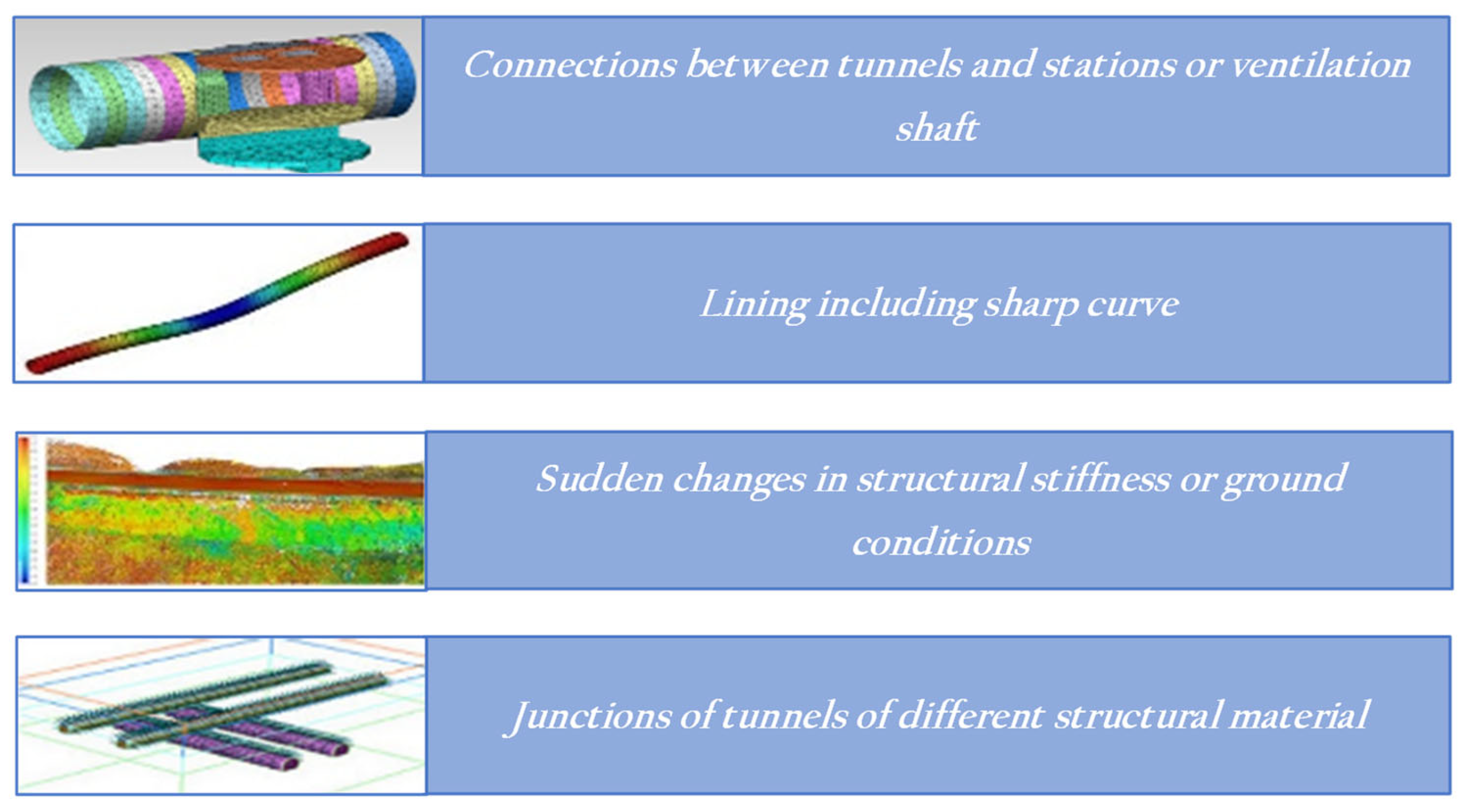
Therefore, careful attention to suitable seismic design is essential. This design criteria must balance the structure’s importance, monetary value, and risk assessment. As shown in Figure 3, earthquake effects should be considered in the following cases:
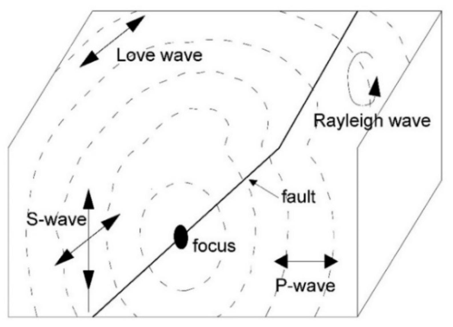
When seismic waves travel through the Earth’s crust, the resulting ground motion is commonly referred to as ground shaking. The severity of the shaking reduces with increasing distance from the fault rupture. There are two different types of seismic waves, and each type has two subtypes. As shown in Figure 4, the different types of seismic waves are what cause the ground to move.
The methods used for seismic analysis and tunnel design may be categorized into the following approaches: free-field deformation, soil–structure interactions, and dynamic earth pressure. Numerous sub-methods are characterized by different degrees of evaluation depending on the initial planning and design, the geological conditions, and the index properties of the ground materials. The analyses are generally grouped into static, dynamic, and fully dynamic categories.
2.4. Concept of Seismic Isolation Systems
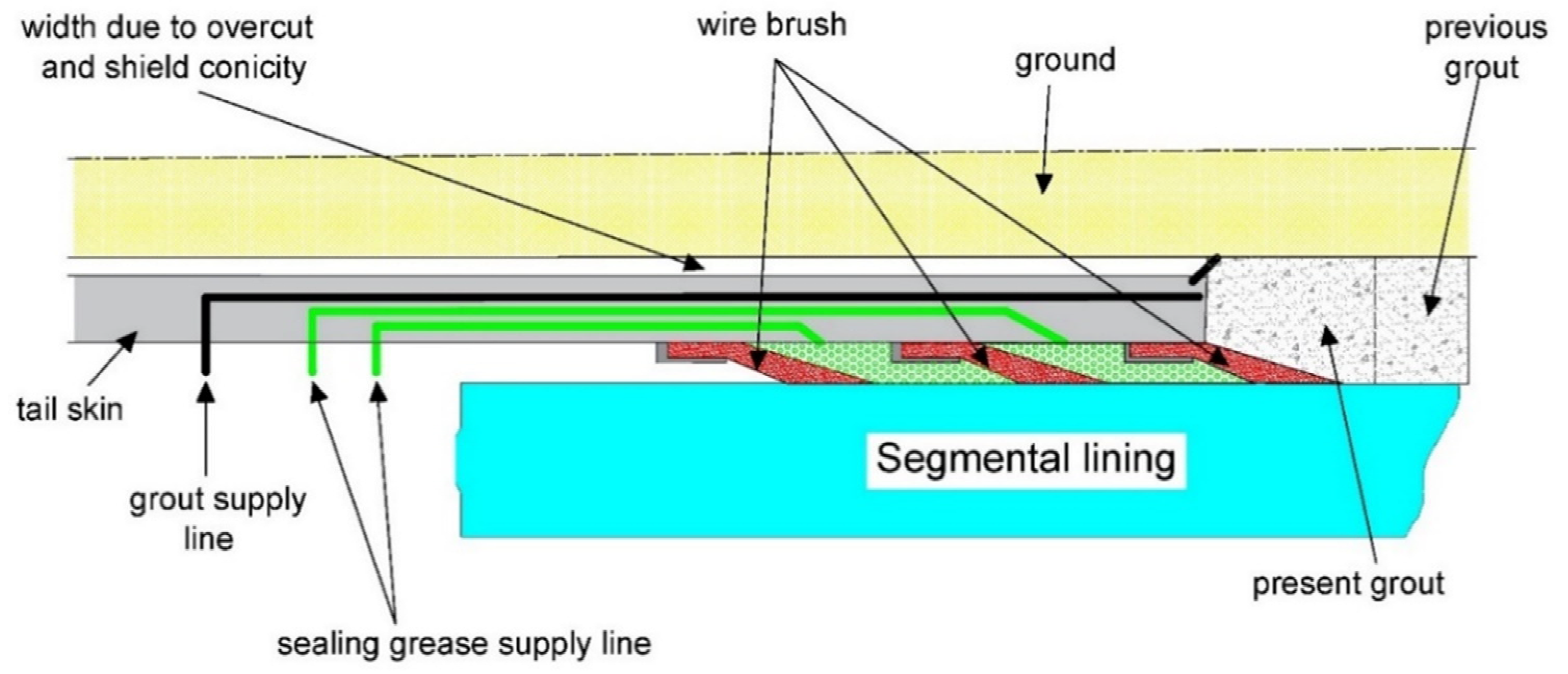
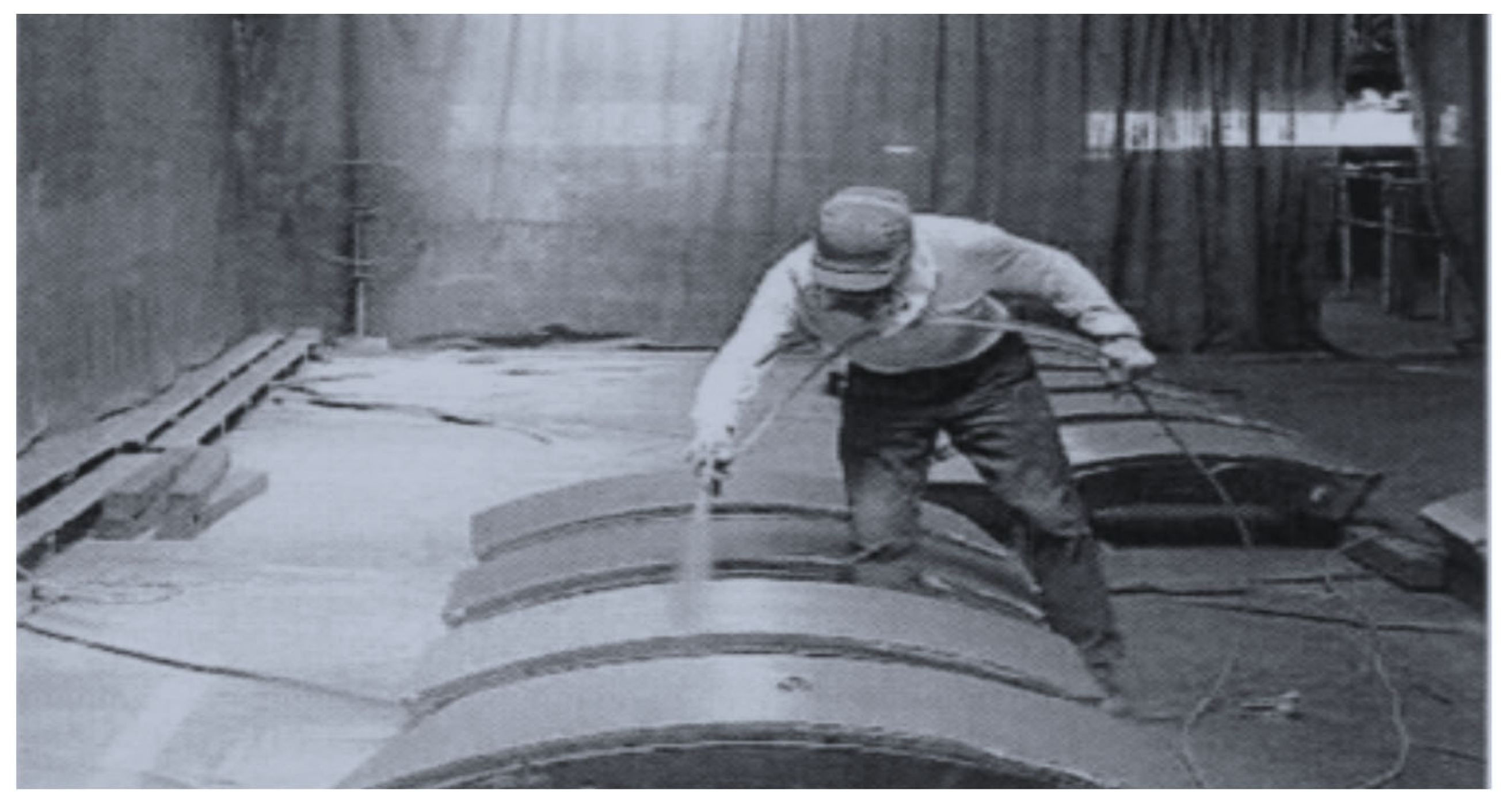
A flexible seismic isolation grout covering the outer tunnel perimeter insulates it from induced deformations of the nearby ground and reduces the stresses induced in the tunnel. The same construction methods used to backfill grout into the tail void apply to shield-driving tunnels or injecting material inside the tunnel, as shown in Figure 5. Additionally, shield segments can be sprayed with silicone paints with a kinetic friction coefficient as low as 0.15 (see Figure 6).
Seismic isolation materials applicable to underground structures must perform seismic isolation functions as backfill materials. The performance requirements for seismic isolation materials for shield-driving tunnels are listed in Table 1. Some frequently used seismic isolation materials are described in Table 2.
The seismic isolation mechanism depends on the stiffness of the isolation layer, which is related to the shear modulus () and Poisson’s ratio (ν) along with the longitudinal and transverse directions of the tunnel, as indicated in the following expressions [79]:
where is the stiffness coefficient of the isolation layer along the longitudinal direction of the tunnel, is the stiffness coefficient of the isolation layer along the transverse direction of the tunnel, R is the isolation layer outer diameter, r is the isolation layer inner is diameter, is the shear modulus of the isolation layer, and is Poisson’s ratio of the isolation layer.
3. Numerical Modeling
The main goal of this research is to show that 3D numerical modeling may be used to forecast and mitigate the effects of seismic loading on tunnels in urban and rural settings. Using a commercial tool called the 3D Finite Element Method, numerical models were made to simulate how soil and tunnels interact with each other.
3.1. Model Establishment
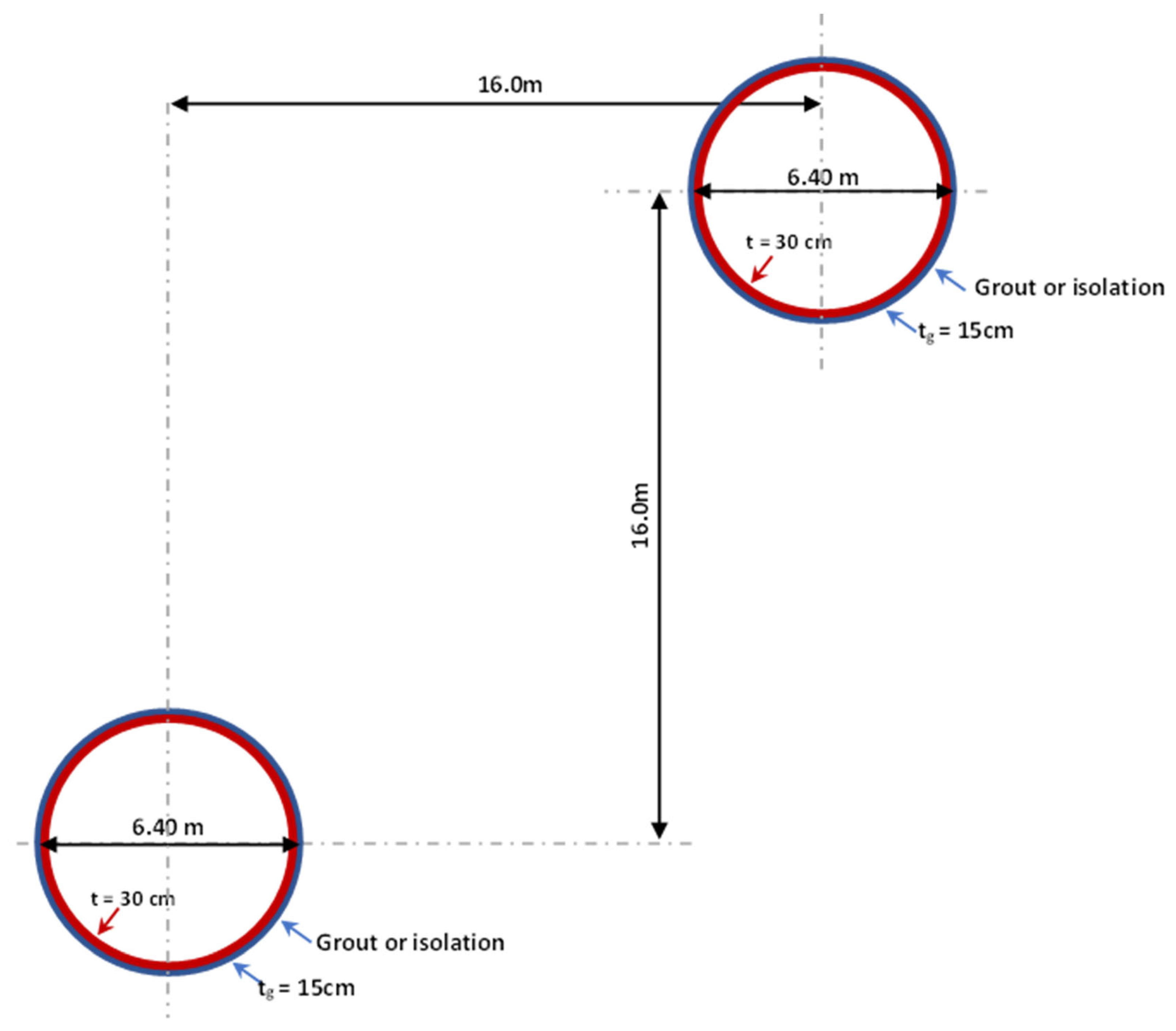
This study considers angular offset tunnels buried in soil with an outer diameter of 6.4 m and a lining cover of 300 mm. As shown in Figure 7, the horizontal and vertical distances between the two centers of twin tunnels are both 16.0 m, which is equivalent to 2.5 times the diameter of the tunnels. The upper tunnel has a burial depth (H) of 12.8 m, while the lower tunnel is 28.0 m from the ground surface and has a segment width of 1.5 m. The dimensions of the overall model in the x-, y-, and z-directions are 76 m 90 m 60 m, respectively. Solid elements were chosen for the ground, tunnel, grout, and isolation coating. The element length was equal to one-eighth of the wavelength of the slowest body wave propagating in the elastic material [80]. The tail hole of the shield machine was thought to need 150 mm of grout or isolation coating to fill it.
The ground had two soil layers, as shown in Figure 8a: an upper layer of soft clay or stiff clay and a lower layer of sand. Another model used in this study assumed that the ground consisted of three soil layers, as shown in Figure 8b. The non-associated Mohr–Coulomb (MC) criteria define the soil behavior. Table 3 shows the material parameters of the soil.
The elastic properties of the materials used in the model are presented in Table 4. The grout properties should be the same or better than the surrounding ground properties in the final state [81].
The MIDAS/GTS-NX FEM software is capable of automatically constraining the model. The nodal degrees of freedom (DOF) along the model’s vertical sides are constrained in the x-direction, and the model is constrained in the y-direction at the front and back. For the bottom nodes, the DOF in the z-direction is constrained in the y-and x-directions. The DOFs along the ground surface are not constrained.
The isolation material used in the model is silicon-based [82,83]. Silicon is the most common material used for seismic isolation. This material is composed of silicon oil and fly-ash and has a shear modulus () that is ( and ) of the shear modulus of the soil () around the tunnel. A lower shear modulus in the isolation material produces a better effect in the isolation layer [83]. The remaining properties of this material are listed in Table 5.
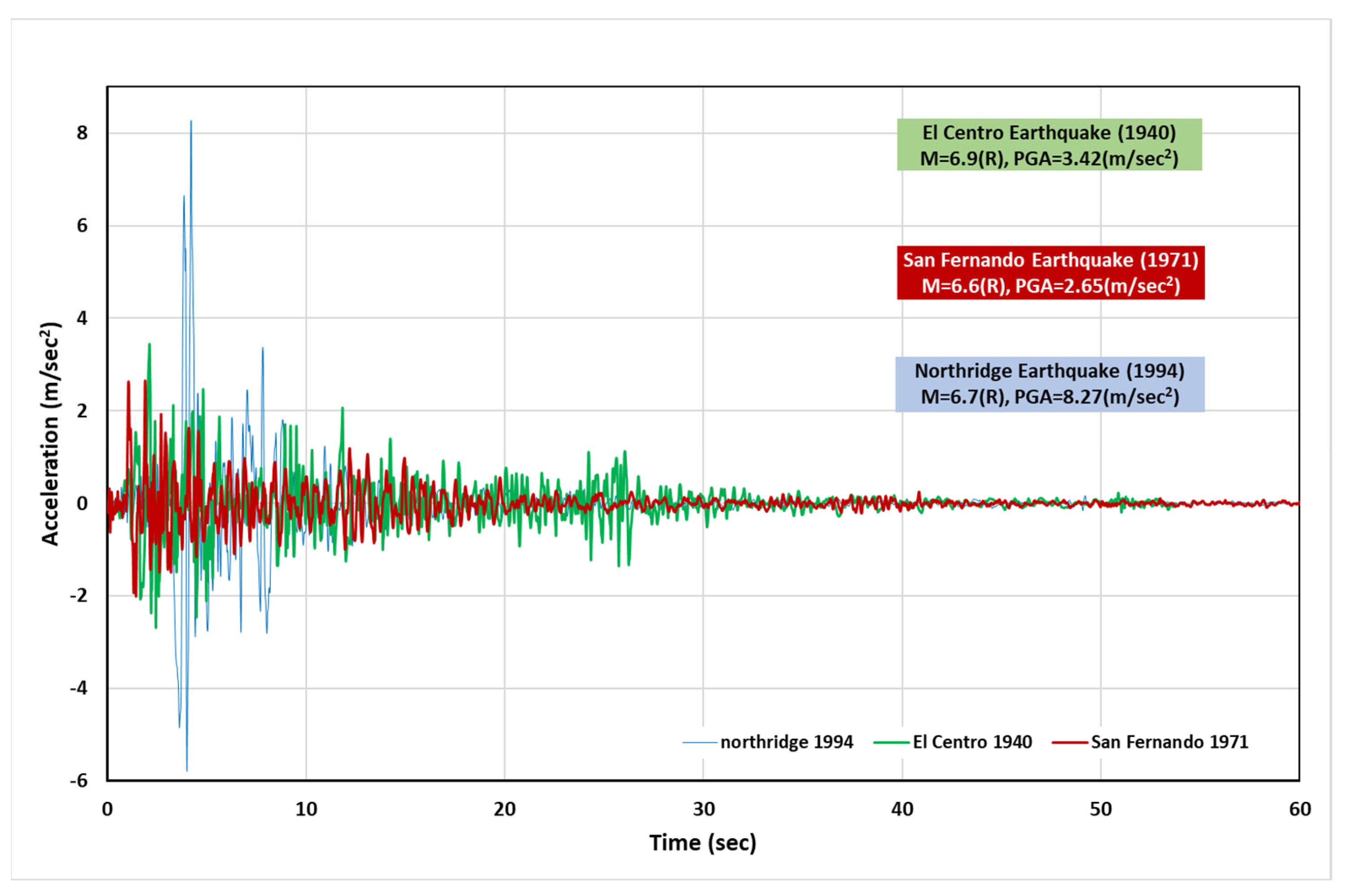
A linear dynamic time history analysis using the direct integrating method was applied. The dynamic excitation sources applied perpendicular to the tunnel axis were the El Centro 1940, San Fernando 1971, and Northridge 1994 data from the MIDAS/GTS-NX library, as shown in Figure 9. The peak ground acceleration was 0.30 g. The duration of excitation in this study was 15 s with a time step of 0.02 s, i.e., 750 steps.
3.2. Model Development
The 3D model calculations were processed by MIDAS/GTS-NX, which calculates stresses and deformations in the soil and the structure, taking into account the elastoplastic behavior of the soil modeled using the MC criteria. As shown in Figure 10, thirty-six FEM models were looked at to see how stable the tunnel was under seismic loading.
4. Results and Discussion
The effects of using isolation on the tunnel’s vertical displacement (settlement or heave) are currently being examined. This study focuses on the final displacement of the tunnels and their induced stresses in the transverse direction, where the tunnels are structures that resist movement in the transverse direction. According to the European design code, the principal compression and tension stresses and the allowable stress are equal to 400 kN/m2, leading to allowable tensile stress of 3200 kN/m2 and compression stress of 23,000 kN/m2. The three earthquake time histories used in this study are thought to be accurate for actual design work because they get the best response.
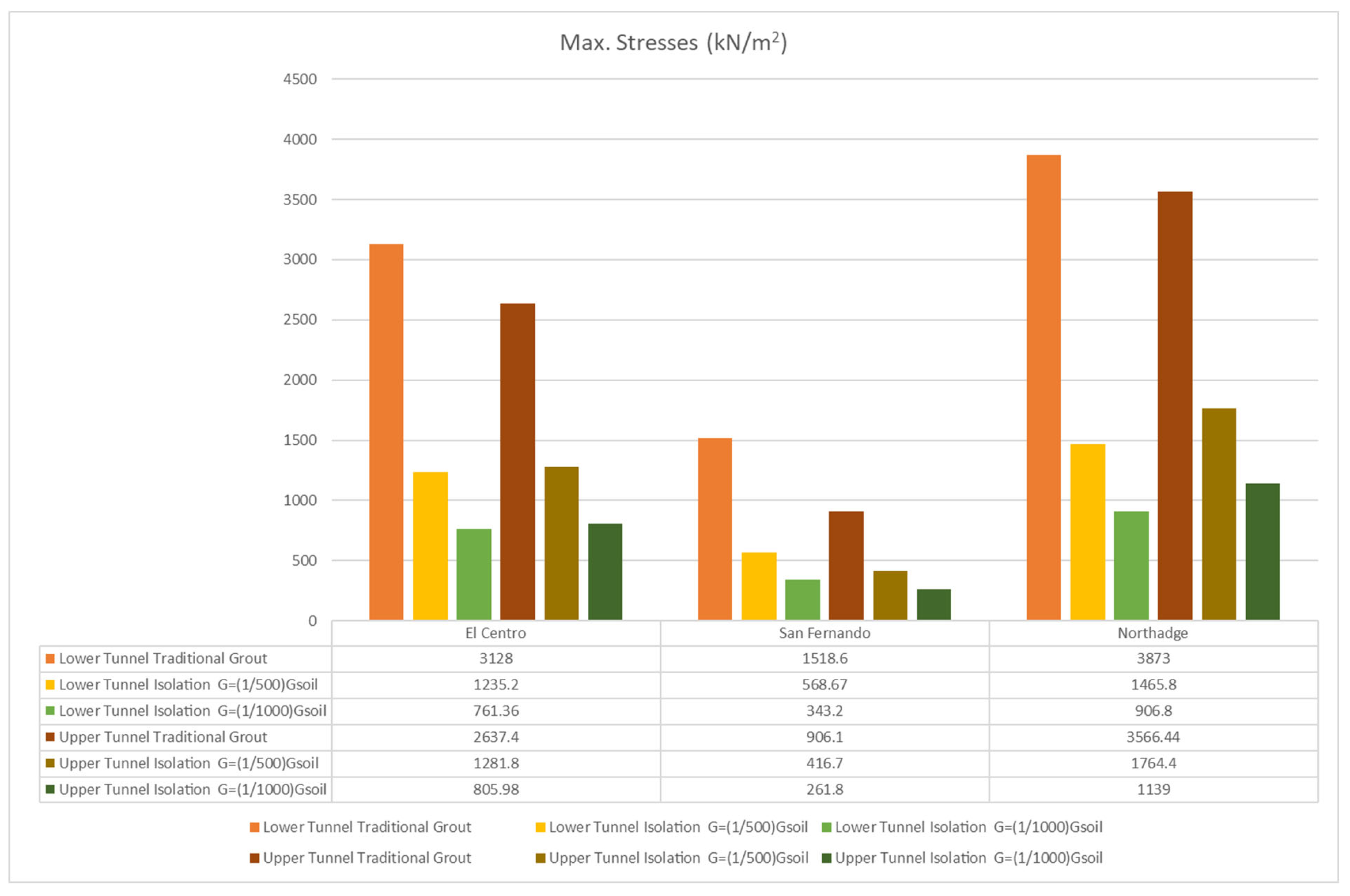
The seismic response of the lower (deeper) tunnel is greater than that of the upper tunnel. In all cases, the compression stresses on the twin tunnels are safe and do not exceed the permissible limits. If twin tunnels are in stiff soil, the tensile stresses induced on the tunnel are unsafe when using traditional grout under the El Centro and Northridge loading. On the other hand, if the twin tunnels are in soft soil, the tensile stress is unsafe in the upper one under Northridge loading, and the lower one is unsafe under both El Centro and Northridge loading. Suppose twin tunnels are in stiff soil when the lower tunnel is in soft soil or stiff soil under a soft soil layer. In that case, the permissible tensile stresses exceed permissible limits when using traditional grout under the El Centro and Northridge loadings. The tensile stresses (maximum stresses) are presented in Figure 11, Figure 12, Figure 13 and Figure 14. In Table 6, the maximum and minimum stresses put on the tunnel by traditional grout and silicon isolation are compared.
A comparison of the stresses under the three earthquake time histories when using traditional grout and using isolation with a shear modulus ratio of and indicates the following:
- In the case where both tunnels are in stiff soil, the average stress decreases by 51.3–76.9% when using isolation instead of traditional grout.
- In the case where both tunnels are in soft soil, the average stress decreases by 50.5–77.4% when using isolation instead of traditional grout.
- In the case where the upper tunnel is in soft soil, and the lower tunnel is in stiff soil, the average stress decreases by 53.6–73.3% when using isolation instead of traditional grout.
- In the case where the upper tunnel is in stiff soil, and the lower tunnel is in soft soil, the average stress decreases by 44.2–79.4% when using isolation instead of traditional grout.
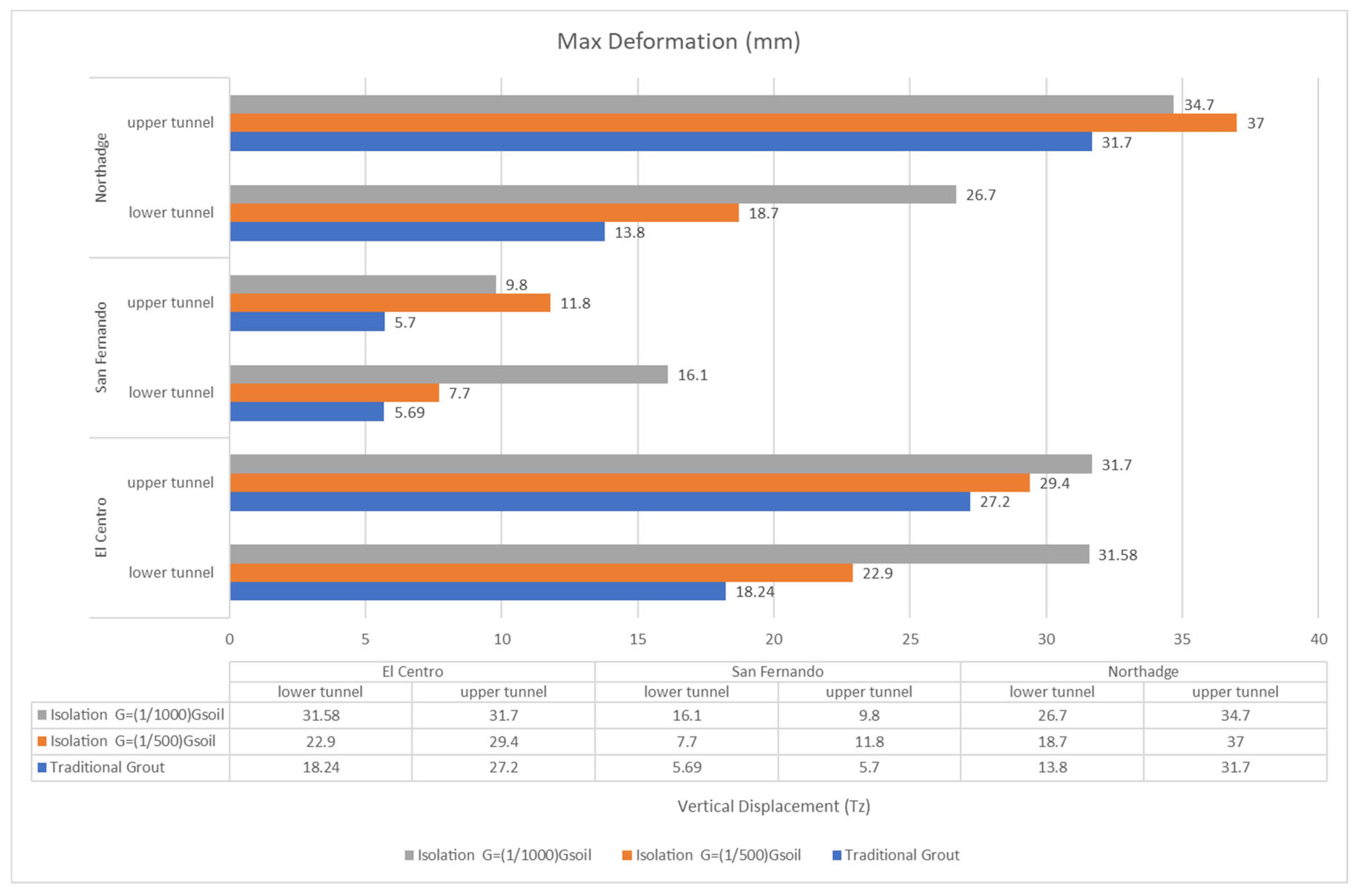
Figure 15, Figure 16 and Figure 17 show that isolation mostly causes the twin tunnels to settle or to move up and down more if there is a quake.
A comparison of the vertical displacement of twin tunnels under the El Centro and Northridge time histories, which recorded the highest values for deformation in comparison with the San Fernando lodging when using traditional grout and using isolation with a shear modulus ratio of and indicates the following:
- 1.
- When both tunnels are in stiff soil, the maximum vertical displacement increases by an average of 23.0% when using and 36.0% when using for the upper tunnel and by 14.0–23.0%, respectively, for the lower tunnel.
- 2.
- When both tunnels are in soft soil, the maximum vertical displacement increases by an average of 17.0% when using and 17.0% when using for the upper tunnel and by 36.0–93.0%, respectively, for the lower tunnel.
- 3.
- The maximum is when the upper tunnel is buried in soft soil and the lower tunnel in stiff soil. Vertical displacement increases by an average of 9.0% when using and 11.0% when using for the upper tunnel and by 46.0–109.0%, respectively, for the lower tunnel.
- 4.
- The maximum is when the upper tunnel is in stiff soil, and the lower tunnel is in soft soil. Vertical displacement increases by an average of 10.0% when using and 35.0% when using for the upper tunnel and by 7.0–34.0%, respectively, for the lower tunnel.
5. Conclusions
Numerical models were used to simulate twin tunnels passing through soft or stiff soil. Various earthquake records were applied as seismic inputs. The effects of a silicon–based isolation material composed of silicon oil and fly–ash were compared with the use of traditional grout for the same results. The models’ results showed that isolation grout produces positive effects on both the compression and tension stresses in the transverse directions of the tunnels.
It cannot insulate the tunnels from the surrounding ground–induced deformation through an isolation layer. Using isolation grout instead of traditional grout has tangible results, especially on average stress. The average stress decreases by 64.10% and 63.95% in the cases where both tunnels are in stiff and soft clay, respectively. In the case where the lower tunnel is in soft soil, the average stress decreases by 61.80%. When the upper tunnel is in soft soil, the average stress has a lower stress of 63.45%.
It is essential to study the reduction in displacement produced by decreasing the shear modulus of the isolation material. In actual design, construction testing should be combined with dynamic results. The compression stresses induced by construction may reduce the tensile stresses resulting from dynamic motions.
This research presents new horizons for using an insulating cover instead of the traditional cover used in tunnels. One of the advantages of using this type of cover is that it significantly reduces the stresses to which the tunnel body is exposed under the influence of seismic activity, exceeding 50% in the case of normal loads. There are different materials that can be used as an insulating cover for tunnels and their suitability and effectiveness need to be proven.
Author Contributions
Conceptualization, A.E., N.E.; methodology, A.E., N.E.; software, N.E.; validation, A.E., N.E.; formal analysis, A.E.; investigation, A.E.; resources, N.E.; data curation, N.E.; writing—original draft preparation, A.E.; writing—review and editing, A.E.; visualization, A.E.; supervision, A.E. All authors have read and agreed to the published version of the manuscript.
Funding
This research received no external funding.
Institutional Review Board Statement
Not applicable.
Informed Consent Statement
Not applicable.
Data Availability Statement
The study contains all data used in the manuscript.
Conflicts of Interest
The authors declare no conflict of interest.
References
- Tunnel Market Survey, 2016—Tunnel (n.d.). Available online: https://www.tunnel–online.info/en/artikel/tunnel_Tunnel_Market_Survey_2016_3051818.html (accessed on 15 January 2020).
- Dowding, C.H.; Rozan, A. Damage to rock tunnels from earthquake shaking. J. Geotech. Eng. Div. 1978, 104, 175–191. [Google Scholar] [CrossRef]
- Yoshikawa, K.; Fukuchi, G. Earthquake damage to railway tunnels in Japan. Adv. Tunn. Technol. Subsurf. Use 1984, 4, 75–83. [Google Scholar]
- Wang, J.M. The distribution of earthquake damage to underground facilities during the 1976 Tang–Shan earthquake. Earthq. Spectra 1985, 1, 741–757. [Google Scholar]
- Wang, J.N. Seismic Design of Tunnels: A Simple State of the Art Design Approach; Parsons Brinckerhoff Inc.: New York, NY, USA, 1993. [Google Scholar]
- Iida, H.; Hiroto, T.; Yoshida, N.; Iwafuji, M. Damage to Daikai subway station. Soils Found. 1996, 36, 283–300. [Google Scholar] [CrossRef]
- An, X.; Shawky, A.; Maekawa, K. The collapse mechanism of a subway station during the Great Hanshin earthquake. Cem. Concr. Compos. 1997, 19, 241–257. [Google Scholar] [CrossRef]
- Huo, H.; Bobet, A.; Fernández, G.; Ramírez, J. Load transfer mechanisms between underground structure and surrounding ground: Evaluation of the failure of the Daikai station. J. Geotech. Geoenviron. Eng. 2005, 131, 1522–1533. [Google Scholar] [CrossRef]
- Montesinos, G.J.P.; Bobet, A.; Ramírez, J.A. Evaluation of soil–structure interaction and structural collapse in Daikai station. ACI Struct. J. 2006, 103, 113–122. [Google Scholar]
- Kontoe, S.; Zdravkovic, L.; Potts, D.; Mentiki, C. Case study on seismic tunnel response. Can. Geotech. J. 2008, 45, 1743–1764. [Google Scholar] [CrossRef] [Green Version]
- Yu, H.T.; Chen, J.T.; Yuan, Y.; Zhao, X. Seismic damage of mountain tunnels during the 5.12 Wenchuan earthquake. J. Mt. Sci. 2016, 13, 1958–1972. [Google Scholar] [CrossRef]
- Huo, H.; Bobet, A.; Fernández, G.; Ramírez, J. Analytical solution for deep rectangular structures subjected to far–field shear stresses. Tunn. Undergr. Space Technol. 2006, 21, 613–625. [Google Scholar] [CrossRef]
- Kontoe, S.; Zdravkovic, L.; Potts, D.; Mentiki, C. On the relative merits of simple and advanced constitutive models in dynamic analysis of tunnels. Geotechnique 2011, 61, 815–829. [Google Scholar] [CrossRef] [Green Version]
- Kampas, G.; Knappett, J.A.; Brown, M.J.; Anastasopoulos, I.; Nikitas, N.; Fuentes, R. The effect of tunnel lining modelling approaches on the seismic response of sprayed concrete tunnels in coarse–grained soils. Soil Dyn. Earthq. Eng. 2019, 117, 122–137. [Google Scholar] [CrossRef]
- Sedarat, H.; Kozak, A.; Hashash, Y.M.A.; Shamsabadi, A.; Krimotat, A. Contact interface in seismic analysis of circular tunnels. Tunn. Undergr. Space Technol. 2009, 24, 482–490. [Google Scholar] [CrossRef]
- Kouretzis, G.; Sloan, S.; Carter, J. Effect of interface friction on tunnel liner internal forces due to seismic S– and P–wave propagation. Soil Dyn. Earthq. Eng. 2013, 46, 41–51. [Google Scholar] [CrossRef]
- Kutter, B.L.; Chou, J.C.; Travasarou, T. Centrifuge testing of the seismic performance of a submerged cut and cover tunnel in liquefiable soils. In Proceedings of the Fourth Geotechnical Earthquake Engineering and Soils Dynamics Conference (GEESDC), Sacramento, CA, USA, 18–22 May 2008. [Google Scholar]
- Chou, J.C.; Kutter, B.L.; Travasarou, T.; Chacko, J.M. Centrifuge modeling of seismically induced uplift for the BART transbay tube. J. Geotech. Geoenviron. Eng. 2010, 137, 754–765. [Google Scholar] [CrossRef]
- Lanzano, G.; Bilotta, E.; Russo, G.; Silvestri, F.; Madabhushi, S.P.G. Dynamic centrifuge tests on shallow tunnel models in dry sand. In Physical Modelling in Geotechnics, Two Volume Sets; CRC Press: Boca Raton, FL, USA, 2010; pp. 561–567. [Google Scholar]
- Lanzano, G.; Bilotta, E.; Russo, G.; Silvestri, F.; Madabhushi, S.P.G. Centrifuge modelling of seismic loading on tunnels in sand. Geotech. Test. J. 2012, 35, 854–869. [Google Scholar] [CrossRef]
- Amorosi, A.; Boldini, D.; Falcone, G. Numerical prediction of tunnel performance during centrifuge dynamic tests. Acta Geotech. 2014, 9, 581–596. [Google Scholar] [CrossRef]
- Conti, R.; Viggiani, G.M.B.; Perugini, F. Numerical modelling of centrifuge dynamic tests of circular tunnels in dry sand. Acta Geotech. 2014, 9, 597–612. [Google Scholar] [CrossRef] [Green Version]
- Tsinidis, G.; Pitilakis, K.; Trikalioti, A.D. Numerical simulation of round–robin numerical test on tunnels using a simplified kinematic hardening model. Acta Geotech. 2014, 9, 641–659. [Google Scholar] [CrossRef]
- Tsinidis, G.; Pitilakis, K.; Madabhushi, G.; Heron, C. Dynamic response of flexible square tunnels: Centrifuge testing and validation of existing design methodologies. Géotechnique 2015, 65, 401–417. [Google Scholar] [CrossRef] [Green Version]
- Tsinidis, G.; Heron, C.; Pitilakis, K.; Madabhushi, G. Centrifuge modelling of the dynamic behavior of square tunnels in sand. In Experimental Research in Earthquake Engineering; Taucer, F., Apostolska, R., Eds.; Geotechnical and Geological Earthquake Engineering; Springer: Cham, Switzerland, 2015; Volume 35, pp. 509–523. [Google Scholar]
- Tsinidis, G.; Rovithis, E.; Pitilakis, K.; Chazelas, J.L. Dynamic response of shallow rectangular tunnels in sand by centrifuge testing. In Experimental Research in Earthquake Engineering; Taucer, F., Apostolska, R., Eds.; Geotechnical and Geological Earthquake Engineering; Springer: Cham, Switzerland, 2015; Volume 35, pp. 493–507. [Google Scholar]
- Tsinidis, G.; Pitilakis, K.; Madabhushi, G. On the dynamic response of square tunnels in sand. Eng. Struct. 2016, 125, 419–437. [Google Scholar] [CrossRef] [Green Version]
- Tsinidis, G.; Rovithis, E.; Pitilakis, K.; Chazelas, J.L. Seismic response of box–type tunnels in soft soil: Experimental and numerical investigation. Tunn. Undergr. Space Technol. 2016, 59, 199–214. [Google Scholar] [CrossRef]
- Esmaeilzadeh Seylabi, E.; Jeong, C.; Dashti, S.; Hushmand, A.; Taciroglu, E. Seismic response of buried reservoir structures: A comparison of numerical simulations with centrifuge experiments. Soil Dyn. Earthq. Eng. 2018, 109, 89–101. [Google Scholar] [CrossRef]
- Hashash, Y.M.A.; Dashti, M.S.; Michael Musgrove, S.M.; Gillis, K.; Martin Walker, M.; Kirk Ellison, M.; Basarah, S.M.Y.I. Influence of tall buildings on seismic response of shallow underground structures. J. Geotech. Geoenviron. Eng. 2018, 144, 04018097. [Google Scholar] [CrossRef]
- Tsinidis, G.; de Silva, F.; Anastasopoulos, I.; Bilotta, E.; Bobet, A.; Hashash, Y.M.; He, C.; Kampas, G.; Knappett, J.; Madabhushi, G.; et al. Seismic behaviour of tunnels: From experiments to analysis. Tunn. Undergr. Space Technol. 2020, 99, 103334. [Google Scholar] [CrossRef]
- Zucca, M.; Valente, M. On the limitations of decoupled approach for the seismic behaviour evaluation of shallow multi–propped underground structures embedded in granular soils. Eng. Struct. 2020, 211, 110497. [Google Scholar] [CrossRef]
- FHWA (Federal Highway Administration). Technical manual for design and construction of road tunnels–Civil elements. In Publication No. FHWA–NHI–10–034; Department of transportation, Federal Highway Administration: Washington, DC, USA, 2009. [Google Scholar]
- Zucca, M.; Crespi, P.G.; Tropeano, G.; Erbì, E. 2D equivalent linear analysis for the seismic vulnerability evaluation of multi–propped retaining structures. In Proceedings of the XVII ECSMGE–2019, Reykjavík, Iceland, 1–6 September 2019; pp. 1–6. [Google Scholar]
- Kampas, G.; Knappett, J.A.; Brown, M.J.; Anastasopoulos, I.; Nikitas, N.; Alonso–Rodriquez, A.; Fuentes, R. Suitability of equivalent linear soil models for analysing the seismic response of a concrete tunnel. In Proceedings of the 16th European Conference of Earthquake Engineering, Thessaloniki, Greece, 18–20 June 2018. [Google Scholar]
- Hwang, J.H.; Lu, C.C. Seismic capacity assessment of old Sanyi railway tunnels. Tunn. Undergr. Space Technol. 2007, 22, 433–449. [Google Scholar] [CrossRef]
- Bilotta, E.; Madabhushi, S.P.G.; Silvestri, F. Editorial: Round Robin Tunnel Test (RRTT). Acta Geotech. 2014, 9, 561–562. [Google Scholar] [CrossRef] [Green Version]
- Tsinidis, G.; Heron, C.; Pitilakis, K.; Madabhushi, G. Physical modeling for the evaluation of the seismic behavior of square tunnels. In Seismic Evaluation and Rehabilitation of Structures, Geotechnical and Geological Earthquake Engineering; Ilki, A., Fardis, M., Eds.; Springer International Publishing: Cham, Switzerland, 2014; pp. 389–406. [Google Scholar]
- Tsinidis, G.; Pitilakis, K.; Anagnostopoulos, C. Circular tunnels in sand: Dynamic response and efficiency of seismic analysis methods at extreme lining flexibilities. Bull. Earthq. Eng. 2016, 14, 2903–2929. [Google Scholar] [CrossRef]
- Wang, C.J. Seismic racking of a dual–wall subway station box embedded in soft soil strata. Tunn. Undergr. Space Technol. 2011, 26, 83–91. [Google Scholar] [CrossRef]
- Hleibieh, J.; Wegener, D.; Herle, I. Numerical simulation of a tunnel surrounded by sand under earthquake using a hypoplastic model. Acta Geotech. 2014, 9, 631–640. [Google Scholar] [CrossRef]
- Gomes, R.C. Numerical simulation of the seismic response of tunnels in sand with an elastoplastic model. Acta Geotech. 2014, 9, 613–629. [Google Scholar] [CrossRef]
- Lanzano, G.; Bilotta, E.; Russo, G.; Silvestri, F. Experimental and numerical study on circular tunnels under seismic loading. Eur. J. Environ. Civil. Eng. 2015, 19, 539–563. [Google Scholar] [CrossRef]
- Abate, G.; Massimino, M.R.; Michele, M. Numerical modelling of centrifuge tests on tunnel–soil systems. Bull. Earthq. Eng. 2015, 13, 1927–1951. [Google Scholar] [CrossRef]
- Kheradi, H.; Ye, B.; Nishi, H.; Oka, R.; Zhang, F. Optimum pattern of ground improvement for enhancing seismic resistance of existing box culvert buried in soft ground. Tunn. Undergr. Space Technol. 2017, 69, 187–202. [Google Scholar] [CrossRef]
- Patil, M.; Choudhury, D.; Ranjith, P.G.; Zhao, J. Behavior of shallow tunnel in soft soil under seismic conditions. Tunn. Undergr. Space Technol. 2018, 82, 30–38. [Google Scholar] [CrossRef]
- Fabozzi, S.; Bilotta, E.; Picozzi, M.; Zollo, A. Feasibility study of a loss–driven earthquake early warning and rapid response systems for tunnels of the Italian high– speed railway network. Soil Dyn. Earthq. Eng. 2018, 112, 232–242. [Google Scholar] [CrossRef]
- Lu, C.C.; Hwang, J.H. Nonlinear collapse simulation of Daikai Subway in the 1995 Kobe earthquake: Necessity of dynamic analysis for a shallow tunnel. Tunn. Undergr. Space Technol. 2019, 87, 78–90. [Google Scholar] [CrossRef]
- Salemi, A.; Mikaeil, R.; Haghshenas, S.S. Integration of finite difference method and genetic algorithm to seismic analysis of circular shallow tunnels (Case study: Tabriz urban railway tunnels). KSCE J. Civ. Eng. 2018, 22, 1978–1990. [Google Scholar] [CrossRef]
- Ding, P.; Tao, L.; Yang, X.; Zhao, J.; Shi, C. Three–dimensional dynamic response analysis of a single–ring structure in a prefabricated subway station. Sustain. Cities Soc. 2019, 45, 71–286. [Google Scholar] [CrossRef]
- Mikaeil, R.; Bakhshinezhad, H.; Haghshenas, S.S.; Ataei, M. Stability analysis of tunnel support systems using numerical and intelligent simulations (case study: Kouhin Tunnel of Qazvin–Rasht Railway). Rud. Geološko Naft. Zb. 2019, 34, 11. [Google Scholar] [CrossRef] [Green Version]
- Al–Mirza, H.A.; Karkush, M.O. Numerical Modeling of Circular Tunnel Alignment Under Seismic Loading. In Geotechnical Engineering and Sustainable Construction; Springer: Singapore, 2022; pp. 15–27. [Google Scholar]
- Bobet, A.; Fakhimi, A.; Johnson, S.; Morris, J.; Tonon, F.; Yeung, M. Numerical Models in Discontinuous Media: A review of advances for rock mechanics applica– tions. ASCE J. Geotech. Geoenviron. Eng. 2009, 135, 1547–1561. [Google Scholar] [CrossRef]
- Power, M.; Rosidi, D.; Kaneshiro, J.; Gilstrap, S.; Chiou, S.J. Summary and evaluation of procedures for the seismic design of tunnels. In Final Report for Task 112–d–5. 3(c); National Center for Earthquake Engineering Research: Buffalo, NY, USA, 1998. [Google Scholar]
- Chen, Z.; Liang, S.; Shen, H.; He, C. Dynamic centrifuge tests on effects of isolation layer and cross–section dimensions on shield tunnels. Soil Dyn. Earthq. Eng. 2018, 109, 173–187. [Google Scholar] [CrossRef]
- Dowding, C.H. Seismic stability of underground openings. In Storage in Excavated Rock Caverns: Rockstore 77; Magnus Bergman, S., Ed.; Pergamon Press: Oxford, UK, 1978; Volume 77, pp. 231–238. [Google Scholar]
- Owen, G.N.; Scholl, R.E. Earthquake engineering of large underground structures. In Report No. FHWA/RD–80/195; 1981; 279p. Available online: https://nehrpsearch.nist.gov/static/files/NSF/PB81247918.pdf (accessed on 25 February 2020).
- Sharma, S.; Judd, W.R. Underground opening damage from earthquakes. Eng. Geol. 1991, 30, 263–276. [Google Scholar] [CrossRef]
- Asakura, T.; Sato, Y. Damage to mountain tunnels in hazard area. Soils Found. 1996, 36, 301–310, (Special Issue). [Google Scholar] [CrossRef]
- Asakura, T.; Sato, Y. Mountain tunnels damage in the 1995 Hyogoken–nanbu Earthquake. Quart. Rep. RTRI 1998, 39, 9–16. [Google Scholar]
- Yashiro, K.; Kojima, Y.; Shimizu, M. Historical earthquake damage to tunnels in Japan and case studies of railway tunnels in the 2004 Niigataken–Chuetsu earth– quake. Quart. Rep. RTRI 2007, 48, 136–141. [Google Scholar] [CrossRef] [Green Version]
- Alderman, J.; Beardall, J.; Campbell, K.; Campbell, R.; Chang, S.; Cole, C.; David, K.; Goltz, J.; Gordon, B.; Lee, M.; et al. The January 17, 1995 Kobe earthquake: An EQE summary report. In EQE International; 1995. Available online: http://www.worldcat.org/title/january–17–1995–kobe–earthquake–an–eqe–summary–report/oclc/32635132 (accessed on 25 February 2020).
- Uenishi, K.; Sakurai, S. Characteristic of the vertical seismic waves associated with the 1995 Hyogo–ken Nanbu (Kobe), Japan earthquake estimated from the failure of the Daikai Underground Station. Earthq. Eng. Struct. Dyn. 2000, 29, 813–821. [Google Scholar] [CrossRef]
- Ma, C.; Lu, D.; Du, D. Seismic performance upgrading for underground structures by introducing sliding isolation bearings. Tunn. Undergr. Space Technol. 2019, 69, 187–202. [Google Scholar] [CrossRef]
- Matsuda, T.; Samata, S.; Iwatate, T. Seismic response analysis for a collapsed underground subway structure with intermediate columns. In The 1995 Hyogoken–Nambu Earthquake: Investigation into Damage to Civil Engineering Structures; Japan Society of Civil Engineers, Committee of Earthquake Engineering: Tokyo, Japan, 1996; pp. 277–285. [Google Scholar]
- Samata, S.; Ohuchi, H.; Matsuda, T. A study of the damage of subway structures during the 1995 Hanshin–Awaji earthquake. Cem. Concr. Compos. 1997, 19, 223–239. [Google Scholar] [CrossRef]
- Kawashima, K. Seismic design of underground structures in soft ground: A review. In Geotechnical Aspects of Underground Construction in Soft Ground; Fujita, K., Miyazaki, Eds.; Balkema: Rotterdam, The Netherlands, 2000. [Google Scholar]
- Kawashima, K. Seismic analysis of underground structures. J. Disaster Res. 2006, 1, 378–389. [Google Scholar] [CrossRef]
- Hashash, Y.M.A.; Hook, J.J.; Schmidt, B.; Yao, J.I.C. Seismic design and analysis of underground structures. Tunn. Undergr. Space Technol. 2001, 16, 247–293. [Google Scholar] [CrossRef]
- Chao, M.; Dechun, L.; Xiuli, D. Seismic performance upgrading for underground structures by introducing sliding isolation bearings. Tunn. Undergr. Sp. Tech. 2018, 74, 1–9. [Google Scholar]
- Ma, S.; Chen, W.; Zhao, W. Mechanical properties and associated seismic isolation effects of foamed concrete layer in rock tunnel. J. Rock Mech. Geotech. Eng. 2019, 11, 159–171. [Google Scholar] [CrossRef]
- Pitilakis, K.; Tsinidis, G.; Chalatis, A. Shallow immersed rectangular tunnel in soft soils. In ISO/TR 12930:2014 Seismic Design Examples Based on ISO 23459; International Organization for Standardization: Geneva, Switzerland, 2014. [Google Scholar]
- Ingerslev, C.; Kiyomiya, O. Earthquake analysis, immersed, and floating tunnels. Tunn. Undergr. Space Technol. 1997, 12, 157–162. [Google Scholar] [CrossRef]
- St John, C.M.; Zahrah, T.F. A seismic design of underground structures. Tunn. Undergr. Space Technol. 1987, 2, 165–197. [Google Scholar] [CrossRef]
- Paolucci, R.; Pitilakis, K. Seismic risk assessment of underground structures under transient ground deformations. In Earthquake Geotechnical Engineering; Pitilakis, K., Ed.; Springer Netherlands, 2007; Volume 6, pp. 433–459. Available online: https://www.springerprofessional.de/en/seismic-risk-assessment-of-underground-structures-under-transien/1579134 (accessed on 25 February 2020).
- Pitilakis, K.; Tsinidis, G. Performance and seismic design of underground structures. In Earthquake Geotechnical Engineering Design; Springer: Cham, Switzerland, 2014; pp. 279–340. [Google Scholar]
- ISO 23469; Bases for Design of Structures—Seismic Actions for Designing Geotechnical Works, International Standard ISO TC98/SC3/WG10. International Organization for Standardization: Geneva, Switzerland, 2005.
- Anastasopoulos, I.; Gerolymos, N.; Drosos, V.; Georgarakos, T.; Kourkoulis, R.; Gazetas, G. Behaviour of deep immersed tunnel under combined normal fault rupture deformation and subsequent seismic shaking. Bull. Earthq. Eng. 2008, 6, 213–239. [Google Scholar] [CrossRef]
- Thewes, M.; Budach, C. Grouting of the annular gap in shield tunnelling—An important factor for minimisation of settlements and production performance. In Proceedings of the ITA–AITES World Tunnel Congress, Budapest, Hungary, 26 May 2009. [Google Scholar]
- Kuhlemeyer, R.L.; Lysmer, J. Finite element method accuracy for wave propagation problems. J. Soil Mech. Found. Div. 1973, 99, 421–427. [Google Scholar] [CrossRef]
- Shimamura, S.; Kasai, H.; Haruumi, M. Seismic isolation effect for a tunnel with a soft isolation layer. Struct. Eng. Earthq. Eng. 1999, 16, 43s–154s. [Google Scholar] [CrossRef] [Green Version]
- Kim, D.S.; Konagai, K. Seismic isolation effect of a tunnel covered with coating material. Tunn. Undergr. Space Technol. 2000, 15, 437–443. [Google Scholar] [CrossRef]
- Li, C.; Chen, W. Seismic isolation effect of foamed concrete layer along the longitudinal direction of a mountainous tunnel. Vibroeng. Procedia 2019, 23, 76–80. [Google Scholar] [CrossRef]
Figure 1.
Underground structure deformation modes caused by earthquakes (after [57]).
Figure 1.
Underground structure deformation modes caused by earthquakes (after [57]).
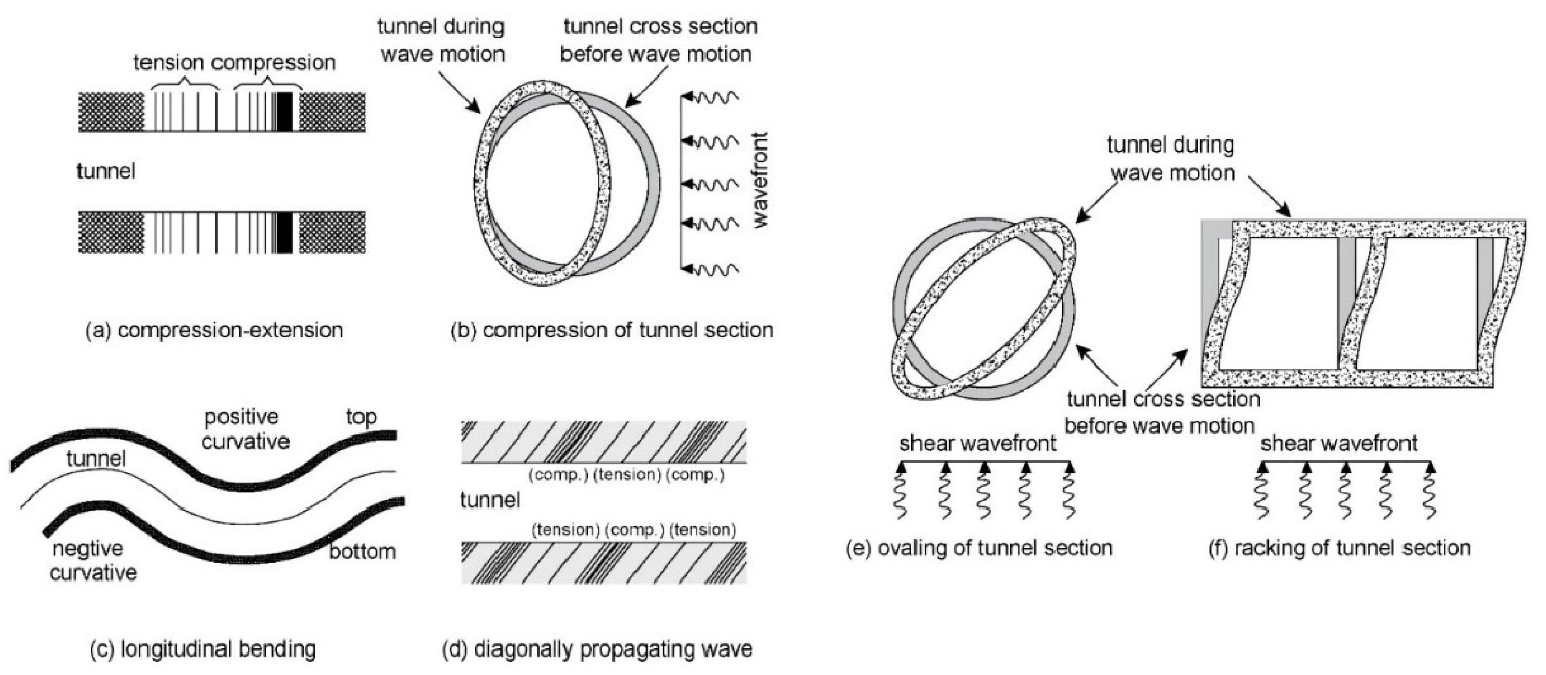
Figure 2.
Causes of earthquake damage to tunnels.
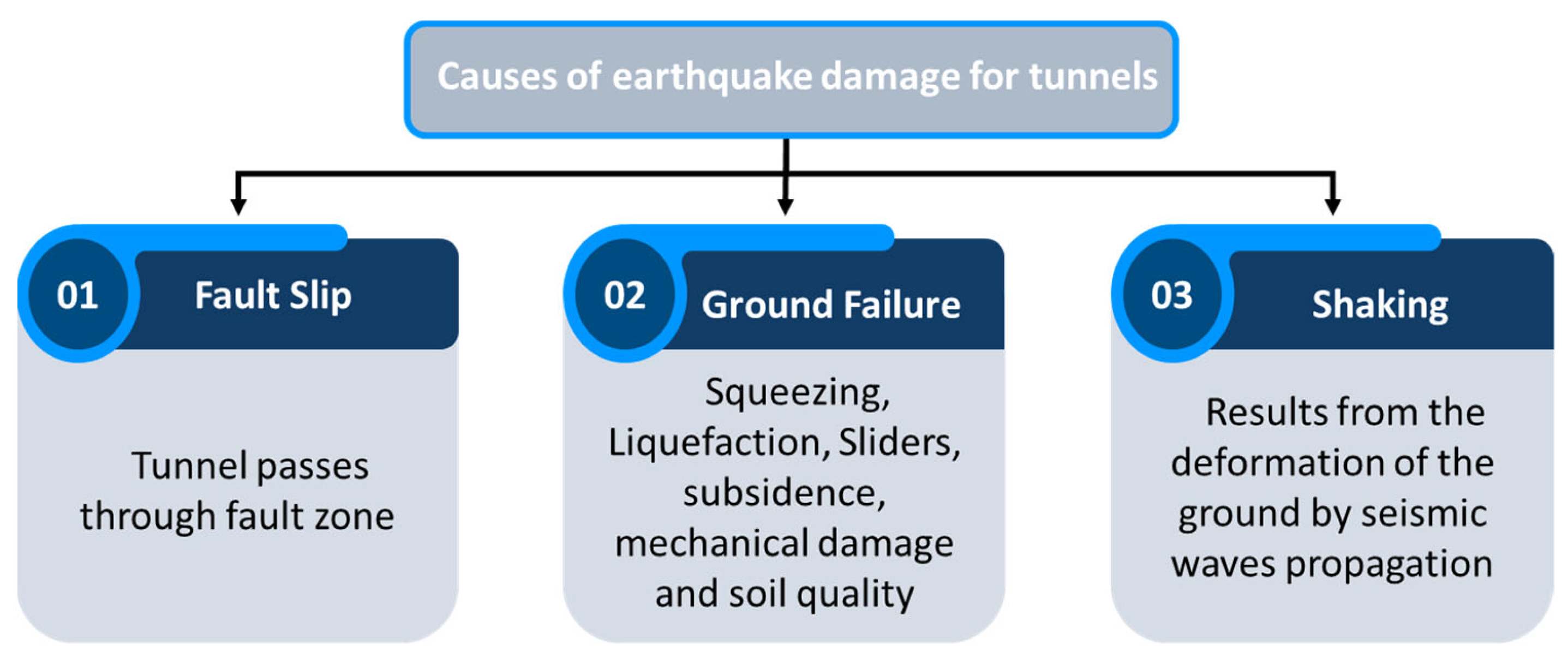
Figure 3.
Conditions for studying the effects of earthquakes.

Figure 4.
The direction of body waves generated by earthquakes.

Figure 5.
Grouting through tail skin.

Figure 6.
Spray coating of paint on shield segments.

Figure 7.
Angular offset tunnel dimensions.

Figure 8.
FEM modeling for the soil and tunnel. (a) Two-layer soil model; (b) three-layer soil model.
Figure 8.
FEM modeling for the soil and tunnel. (a) Two-layer soil model; (b) three-layer soil model.
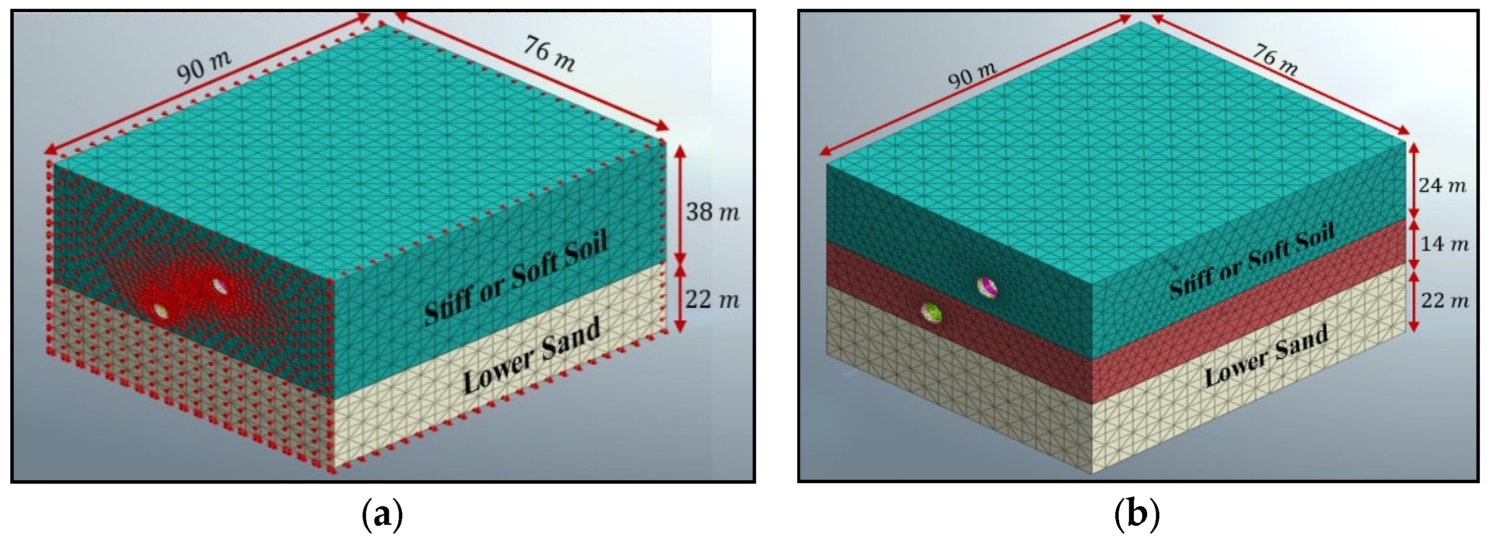
Figure 9.
Acceleration time history.

Figure 10.
Numerical modeling development flowchart.

Figure 11.
Maximum transverse stresses of twin tunnels in stiff soil.
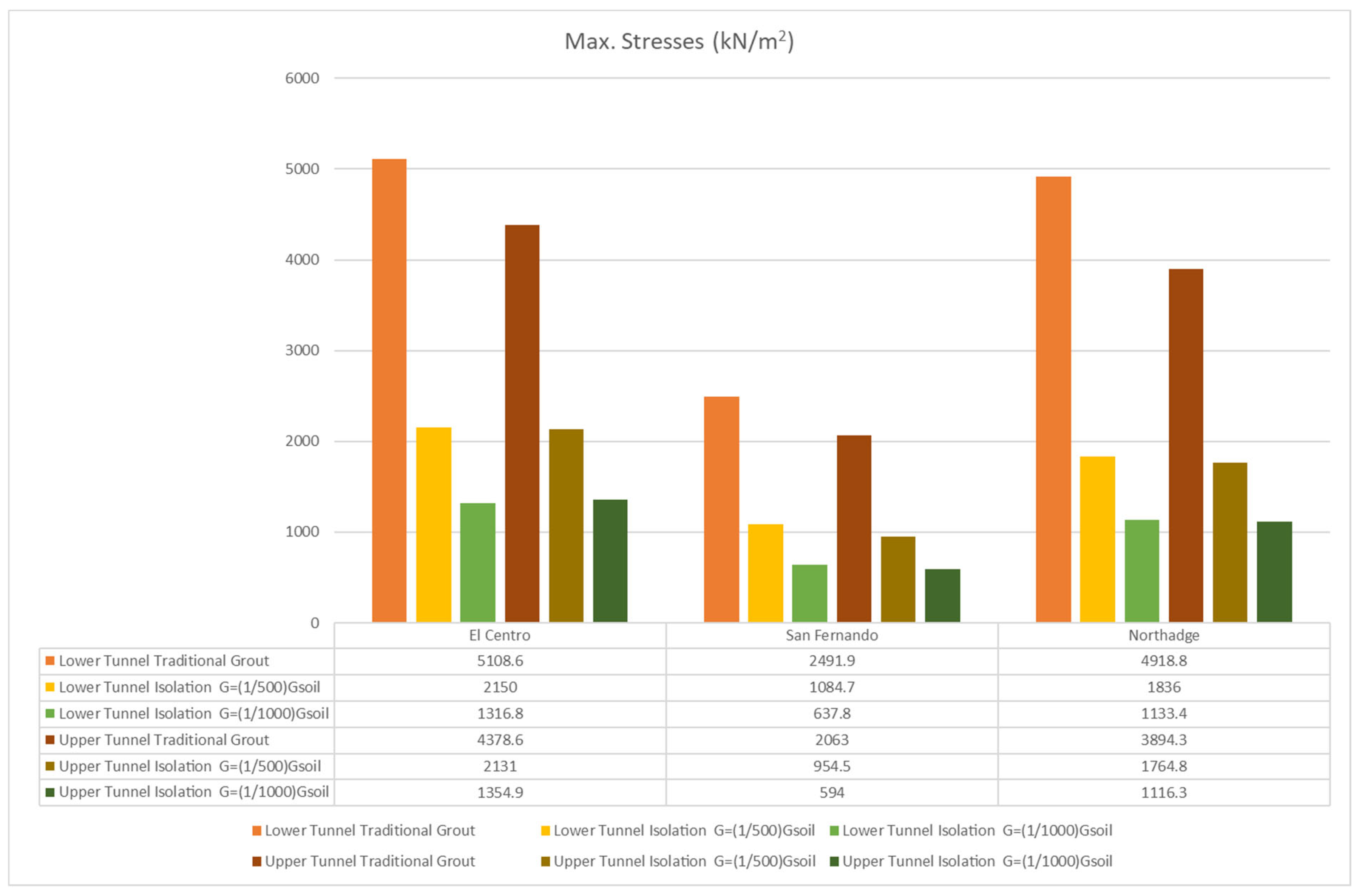
Figure 12.
Maximum transverse stresses of twin tunnels in soft soil.

Figure 13.
Maximum transverse stresses of the upper tunnel in stiff soil and the lower tunnel in soft soil.
Figure 13.
Maximum transverse stresses of the upper tunnel in stiff soil and the lower tunnel in soft soil.

Figure 14.
Maximum transverse stresses of the upper tunnel in soft soil and the lower tunnel in stiff soil.
Figure 14.
Maximum transverse stresses of the upper tunnel in soft soil and the lower tunnel in stiff soil.
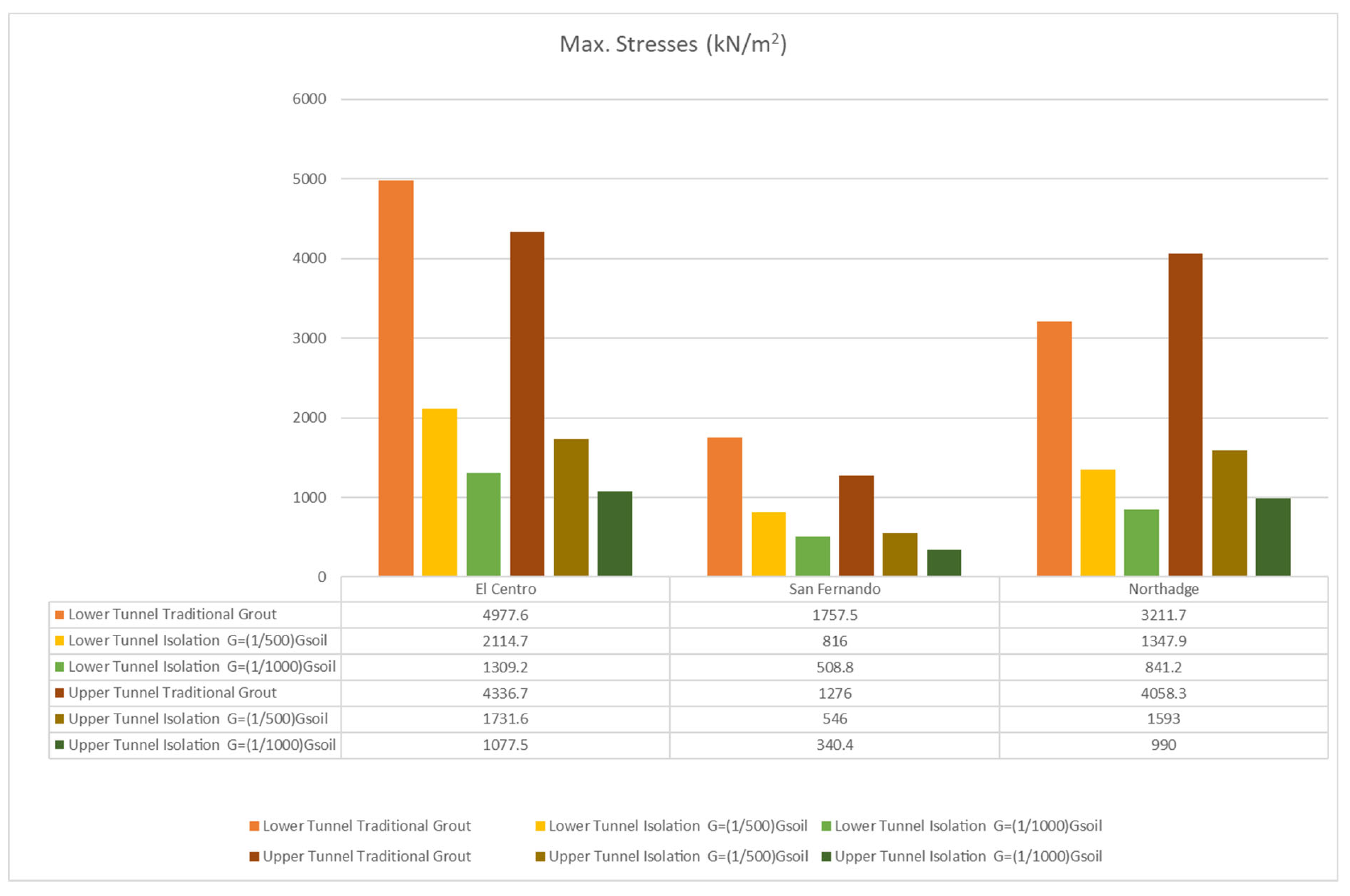
Figure 15.
Maximum vertical displacement of twin tunnels in stiff soil.
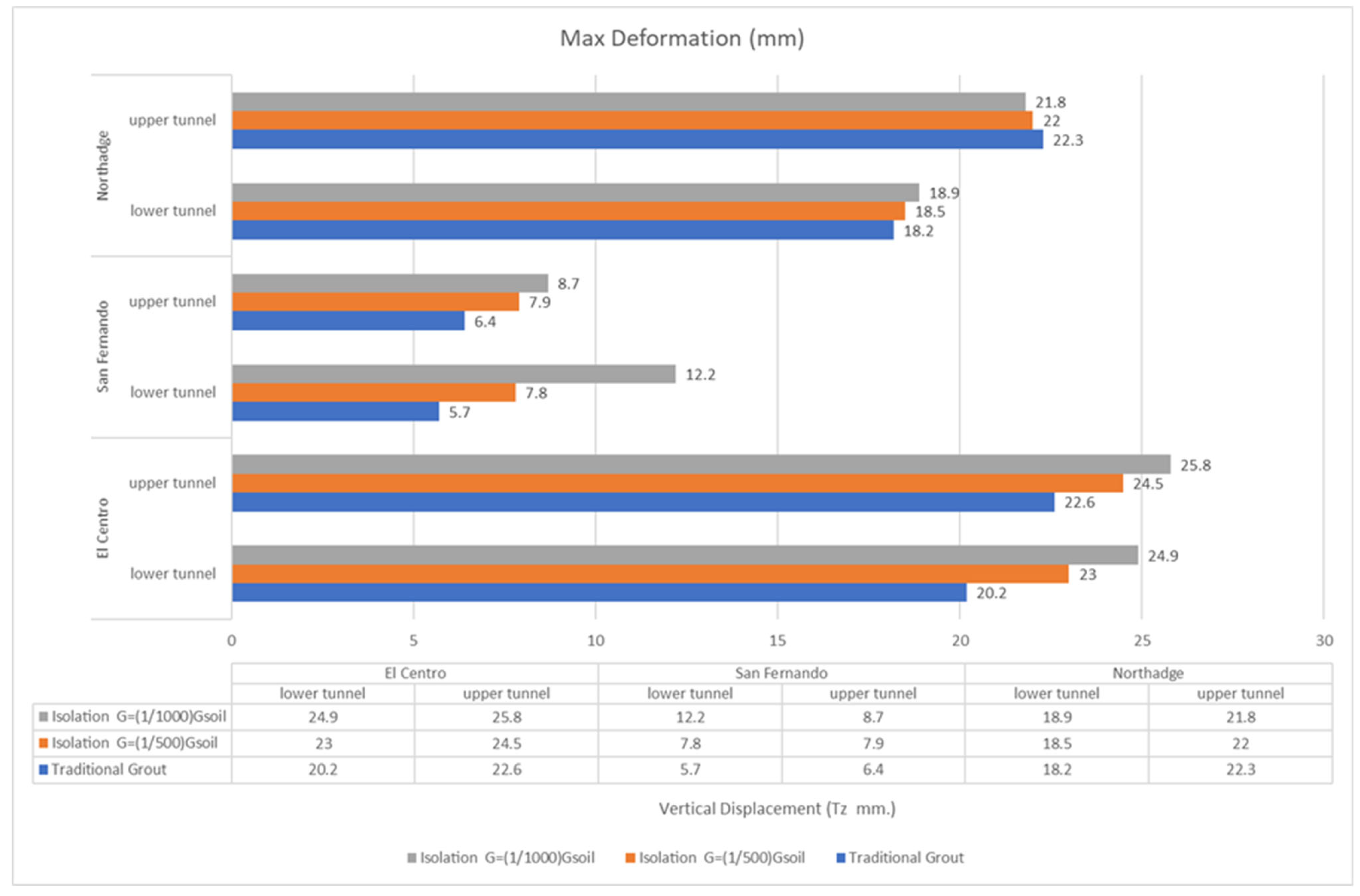
Figure 16.
Maximum vertical displacement of twin tunnels in soft soil.

Figure 17.
Maximum vertical displacement of the upper tunnel in stiff soil and lower tunnel in soft soil.
Figure 17.
Maximum vertical displacement of the upper tunnel in stiff soil and lower tunnel in soft soil.


Table 1.
Requirements for seismic isolation materials.
| Item No. | Description |
|---|---|
| 1 | Low shear modulus and high shear deformability |
| 2 | High durability, long-term stability, and small volumetric changes |
| 3 | High construction ability (i.e., for shield-driving tunnels, transportability by pumping in a liquid state and high filling-up performance) |
| 4 | Water tightness |
| 5 | No dilution by groundwater |
| 6 | No contaminants |
Table 2.
Types of seismic isolation materials [79].
Table 2.
Types of seismic isolation materials [79].
| Construction Method | Isolation Material | Material Contacts |
|---|---|---|
| Shield-driving tunnel | Asphalt-based material | Asphalt and Portland cement with high-water-absorbing polymer |
| Urethane-based material | Urethane with fly ash and polymer | |
| Silicon-based material | Silicon oil and fly ash with polyether |
Table 3.
Properties of soil materials.
| Material | Modulus of Elasticity (E) (kN/m2) | Poisson’s Ratio (ν) | Unit Weight (γ) (kN/m3) | Cohesion (cu) (kN/m2) | Friction Angle (φ) (0) |
|---|---|---|---|---|---|
| Soft clay | 25,000 | 0.48 | 19.00 | 30.00 | 0.00 |
| Stiff clay | 75,000 | 0.45 | 20.00 | 60.00 | 0.00 |
| Lower sand | 90,000 | 0.35 | 20.00 | 0.00 | 38.00 |
Table 4.
Properties of concrete lining and grout materials.
| Material | Modulus of Elasticity (E) (kN/m2) | Poisson’s Ratio (ν) | Unit Weight (γ) (kN/m3) |
|---|---|---|---|
| Concrete for segment | 30 × 106 | 0.20 | 25.00 |
| Grout for tunnel in soft clay | 40,000 | 0.30 | 20.00 |
| Grout for tunnel in stiff clay | 100,000 | 0.30 | 20.00 |
Table 5.
Material properties of silicon-based isolation material.
| Material | Shear Modulus (G) (kN/m2) | Poisson’s Ratio (ν) | Unit Weight (γ) (kN/m3) |
|---|---|---|---|
| Isolation for tunnel in soft clay | 20/10 | 0.48 | 10.00 |
| isolation for tunnel in stiff clay | 50/25 | 0.48 | 10.00 |
Table 6.
Effect of using isolation instead of traditional grout.
| Tunnel Description | Isolation Shear Modulus | Lower Tunnel | Upper Tunnel | ||
|---|---|---|---|---|---|
| Compression (Minimum Stresses) | Tension (Maximum Stresses) | Compression (Minimum Stresses) | Tension (Maximum Stresses) | ||
| Twin tunnels in stiff soil | ––(73.0–74.9)% | ––(74.0–76.9)% | ––(70.4–71.4)% | ––(69.0–61.3)% | |
| ––(57.0–59.0)% | ––(56.5–62.7)% | ––(52.5–54.8)% | ––(51.3–54.7)% | ||
| Twin tunnels in soft soil | ––(72.9–77.3)% | ––(75.7–77.4)% | ––(68.9–71.0)% | ––(68.0–71.0)% | |
| ––(56.5–63.0)% | ––(60.5–62.6)% | ––(51.6–54.7)% | ––(50.5–54.0)% | ||
| Upper tunnel in soft soil and lower tunnel in stiff soil | ––(72.3–73.8)% | ––(71.0–73.7)% | ––(72.9–74.7)% | ––(73.3–75.6)% | |
| ––(55.5–57.5)% | ––(53.6–58.0)% | ––(57.0–59.4)% | ––(57.2–60.8)% | ||
| Upper tunnel in stiff soil and lower tunnel in soft soil | ––(77.2–79.4)% | ––(76.3–77.6)% | ––(63.8–64.6)% | ––(63.8–66.6)% | |
| ––(63.8–64.6)% | ––(61.8–63.3)% | –(44.8–44.0)% | –(44.2–47.5)% | ||
(–) sign means reduce.
Publisher’s Note: MDPI stays neutral with regard to jurisdictional claims in published maps and institutional affiliations. |
© 2022 by the authors. Licensee MDPI, Basel, Switzerland. This article is an open access article distributed under the terms and conditions of the Creative Commons Attribution (CC BY) license (https://creativecommons.org/licenses/by/4.0/).
Share and Cite
MDPI and ACS Style
Elgamal, A.; Elfaris, N. Adverse Impact of Earthquake Seismic Loading on Angular Offset Tunnels and Effects of Isolation Grout. Infrastructures 2022, 7, 87. https://doi.org/10.3390/infrastructures7070087
AMA Style
Elgamal A, Elfaris N. Adverse Impact of Earthquake Seismic Loading on Angular Offset Tunnels and Effects of Isolation Grout. Infrastructures. 2022; 7(7):87. https://doi.org/10.3390/infrastructures7070087
Chicago/Turabian StyleElgamal, Ahmed, and Nissreen Elfaris. 2022. "Adverse Impact of Earthquake Seismic Loading on Angular Offset Tunnels and Effects of Isolation Grout" Infrastructures 7, no. 7: 87. https://doi.org/10.3390/infrastructures7070087