1. Introduction
When dealing with complex samples, one of the main bottlenecks from the practical point of view is their preparation. A suitable sample preparation method should allow saving time during data acquisition, enhancing the S/N ratio, improving the detection limits, etc. Considering particulate matter (PM) analysis of solutions, the most common preparation technique is filtration: it is easy, reliable, and fast, but at the same time, it presents some drawbacks. Indeed, it requires a considerable sample consumption and PM whose size is smaller than the one of the filtration pores, which are not retained on the filter. To avoid this point, the original solution could be deposited on a membrane presenting a quite large surface (about 1 cm2). In this case a critical issue is the low superficial density of the PM deposited on top of it.
The evaporation process, based on the deposition of micro-droplets, may overcome both issues. Indeed, the microdrop technique consists in the deposition of PM in association to liquid drops presenting a diameter between 70 and 200 µm. After the evaporation of the solvent, the PM depositional pattern resembles the one of the original droplets. The main disadvantages of this method are the inhomogeneity of the deposition and the long time required for the evaporation of the solvent. In fact, the evaporation of large drops (few mm of diameter) can last several hours. At normal conditions of temperature and humidity, full evaporation of drops of water can require more than 10 h per mL, and the density fluctuation of the deposited material is up to 80% as a consequence of the so-called coffee-stain effect [
1]. To optimize the process, we deposit micro-droplets and control the deposition area with motorized translational stages. To this purpose, a study of the evaporation dynamics is necessary to investigate the uniformity of deposition and to evaluate the evaporation rate of micro-droplets presenting different sizes. When dealing with densely-packed deposition patterns, our results show that is necessary to consider the interaction between different evaporating droplets.
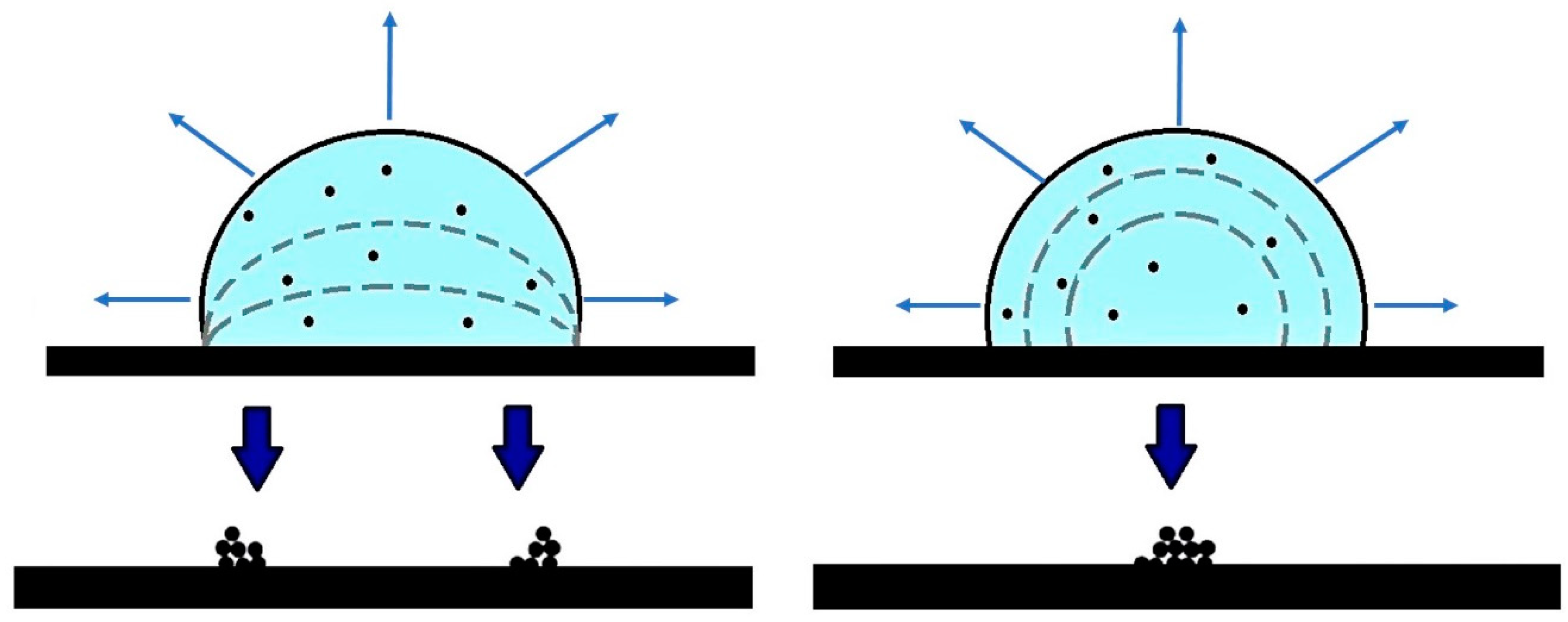
The evaporation of a drop on a surface can be described with two different models: the evaporation with a “constant contact area” and that with a “constant contact angle” [
2] (see
Figure 1).
In the first case, the evaporation takes place, maintaining a constant contact area between the liquid drop and the surface. The shape of the drop remains almost “spherical” [
2], but the contact angle decreases. In accordance to the second model, the contact angle of the edge of the drop is constant during the evaporation [
2], thus, the shape of the drop remains “spherical”, but the contact area between liquid and surface continuously decreases. The “constant contact area model” is suitable when a strong interaction between the liquid and the substrate takes place, e.g., when considering water and a hydrophilic surface [
3,
4]. This is clear in the work of Peschel et al., where at higher concentration, the evaporation occurs with the constant area mode, i.e., during the evaporation, the droplet does not shrink [
5].
On the opposite, the second model is more appropriate when the drop-substrate interactions are weak, as in the case of water on a hydrophobic substrate. As studied by Fittschen et al. [
6], an ultra-diluted solution is characterized by a low solution–substrate interaction, and the coffee stain phenomenon is reduced. As a matter of fact, the insoluble components deposed by the evaporation of the droplets have to be characterized in order to achieve the most homogeneous deposition starting from defined droplet size. As shown by Sparks et al., droplet dimension and solution concentration are the main parameters that control the deposition [
7]. Thus, the deposition method we presented can be a fast, simple, and direct way to achieve a homogeneous deposition of insoluble materials considering only the droplet size and the concentration of the solution.
In this contribution, we will describe the optimization process of an experimental setup based on the evaporation of water micro-droplets in accordance to the constant angle model. The uniformity of the deposition will be determined, and results will be compared to those obtained through the standard filtration method. Indeed, the microdrop method may offer many opportunities and dedicated preparations in different scientific fields. One particular demanding application is the homogeneous deposition onto specific substrates of inorganic components, e.g., coarse particles, mineral fractions, and particulate matter for spectroscopic characterizations. Research that could benefit from this particular type of sample preparation are ice core studies or detection of heavy metals present in ultra-trace elements.
2. Experimental
Using a micro-dispenser, micro-sized droplets can be deposited, controlling the spatial distribution of drops, their size, and the deposition rate. The Microdrop technology [
8] allows spreading of extremely small amounts of a liquid solution. Moreover, thanks to dedicated devices, it is possible to deposit single droplets whose volume is in the sub-nanoliter range. Such small droplets present an interaction with the substrate, which can be considered negligible. The micro-dispenser is composed of a head with a nozzle and a pumping chamber working with the same piezoelectric technology used for inkjet printers. The head is controlled by a driver, i.e., a pulse generator, which controls the piezoelectric actuator and sends pulses to the head. The device we used is the MD-K-130 (© Microdrop Technologies GmbH, Norderstedt, Germany). With an inner nozzle diameter of 70 µm, we may produce, with 1% volume repeatability, droplets with a minimum nominal volume of 180 pl and at a drop rate from 1 to 2000 Hz [
8,
9]. To prepare a sample with a specific microdrop pattern, it is necessary to control the number of drops on the substrate, releasing each of them at a well-defined and repeatable distance. In our experimental setup, to generate the pattern, the head is maintained fixed while the substrate translates under the stream of droplets released by the head. The motion of the substrate is realized with two precision PI Micos (Physik Instrumente GmbH Karlsruhe, Karlsruhe, Germany) Translational Stage VT-80 stages, assembled perpendicularly with respect to each other. This setting allows positioning the substrate with a nominal accuracy of 1 µm per axis. The desired spatial patterns are obtained controlling the two translation stages with a LabView©-based code and properly setting the Microdrop dispenser [
9].
The characterization of the evaporation time and of the drop pattern was made with the Zeiss Axio Imager M1 optical microscope (Carl Zeiss Microscopy LLC, Oberkochen, Germany) using 5×, 10×, and 20× magnification optics. The video camera had a x–y spatial resolution of 0.13 µm at 5×, 0.26 µm at 10×, and 0.52 µm at 20× magnification and allowed us to measure the droplet volume with an uncertainty of ~3% of the measured volume. We used a solution of ink and water (Gullor® ink diluted at 50% with high purity milliQ water) for the optical analysis of the deposition, and high purity milliQ water for the evaporation dynamic measurements, i.e., the diameter of the drop and the angle of contact. The substrates we used for the evaporation analysis were Kapton® polyimide films from DuPont of 0.005’ (125 µm) thickness, while we used polycarbonate Nucleopore© membrane filters (pore size 0.45 μm and filter area diameter ~20 mm) for the analysis of morphology on evaporated samples morphology by X-Ray Fluorescence.
The evaluation of the PM deposition uniformity has been performed using the X-ray fluorescence technique at the beamline B18 at the
Diamond Light Source facility (Harwell, United Kingdom) [
10], using a monochromatic X-ray beam at 8 keV, with a focus of 100 µm radius and a detection limit of 100 ng/mm
2.
The evaluation of the evaporation was carried out measuring the diameter and height of droplets as a function of time using the optical microscope and the camera. We measured the parameters of the single droplets and of groups of droplets to evaluate the evaporation rate as a function of the size and of the distance between several droplets. We then identified the minimum deposited area achievable with the evaporation of small droplets, in the shortest time. To optimize the deposition process, all images and experimental parameters were analyzed and used to write an approximate model.
3. Results
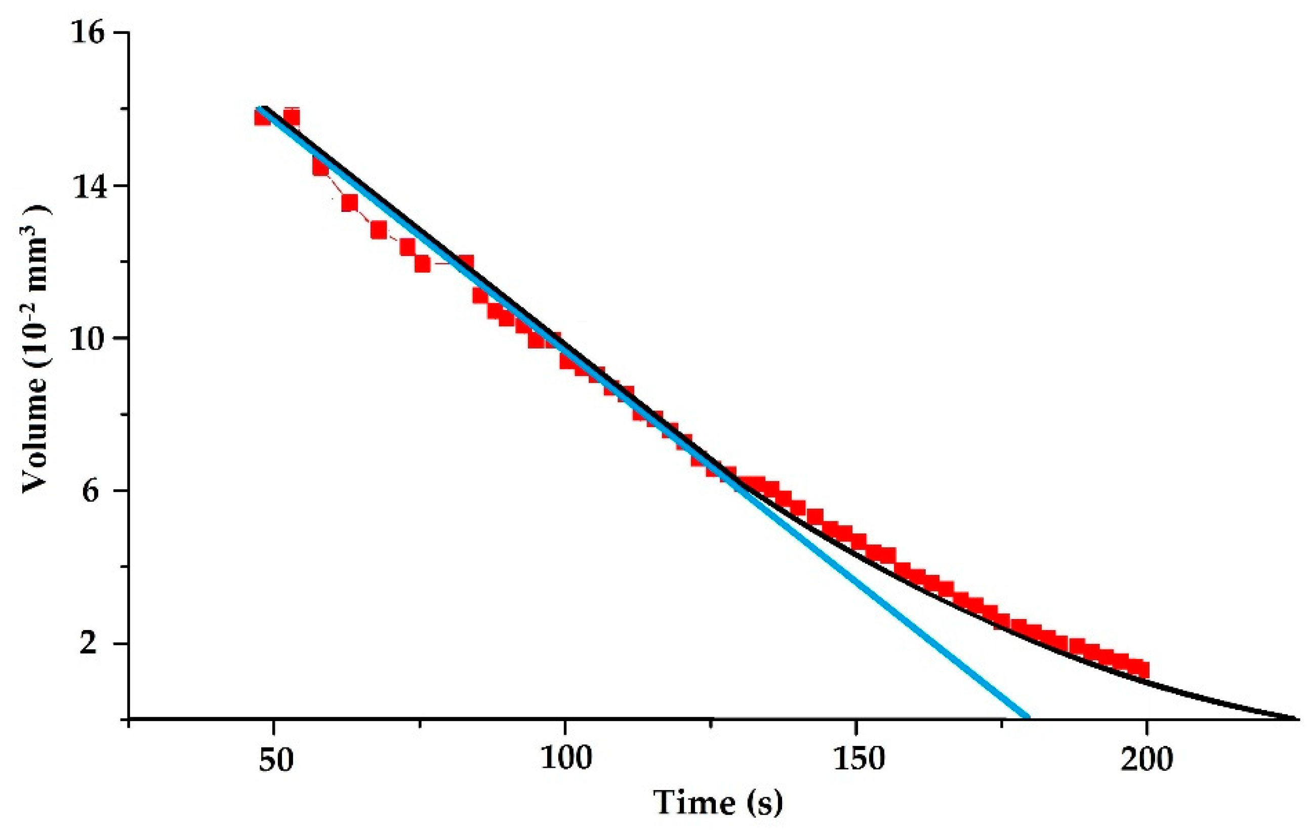
The analysis of the images of the droplets (see
Figure 2) and of the measured parameters clearly points out that when using a low concentration solution and a hydrophobic substrate such as
Kapton, the evaporation occurs in accordance to the “constant angle” model, well described by the theoretical model introduced by Picknett and Bexon in 1977 [
2]. The result is confirmed in
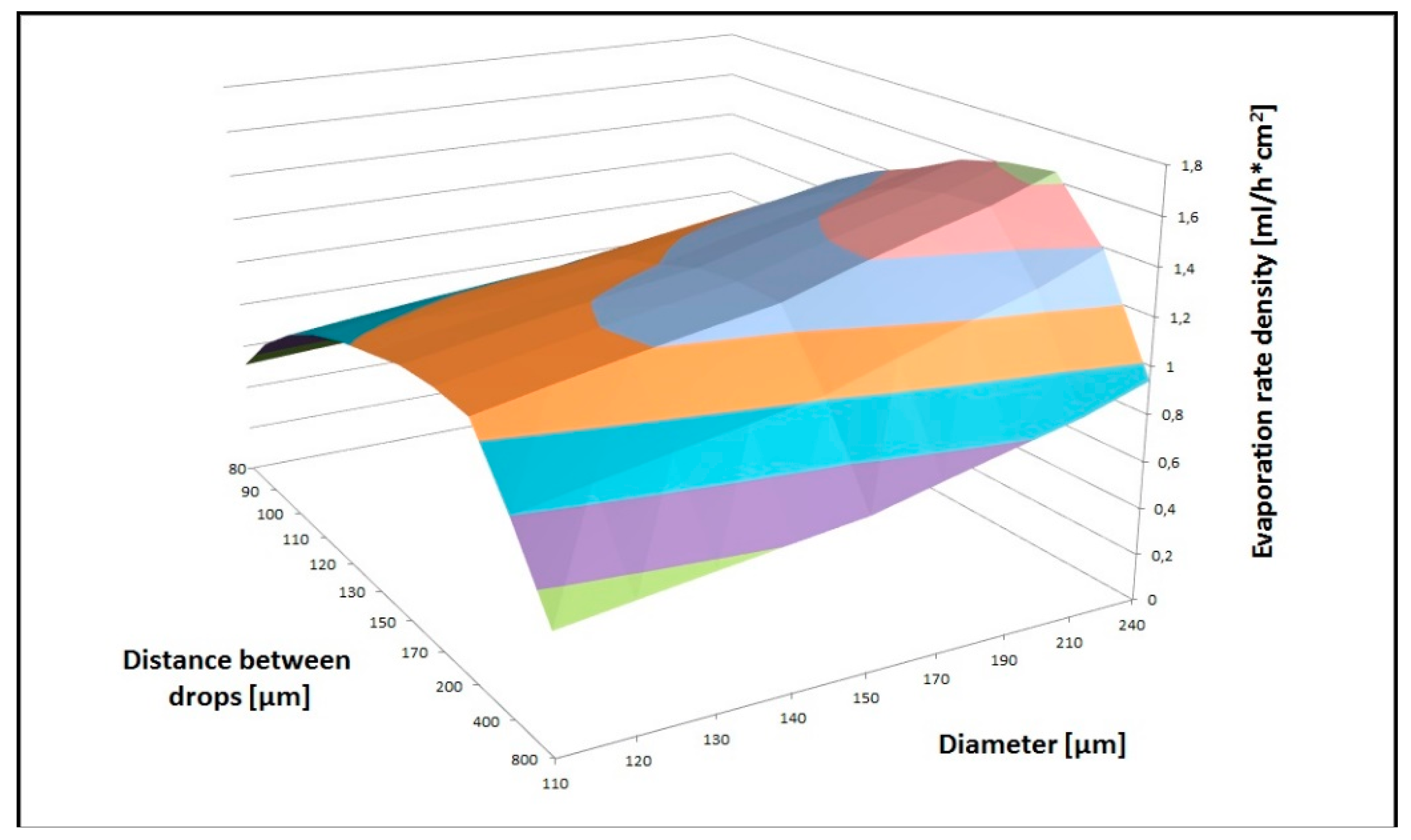
Figure 3, where our data are compared to the “constant angle” and “constant contact area” models. The deposition rate, i.e., the volume of the liquid deposited vs. time, was optimized considering the velocity of the stages and the spatial pattern parameters of the deposited droplets. Indeed, a fundamental parameter that drives the evaporation is the saturation of the atmosphere surrounding the droplets’ selves, which is directly related to the mutual position of the droplets. Different droplet sizes and different distances between successive droplets were considered to this aim. In
Figure 4, we show the correlated parameters of the deposition tests we performed using the translation stages combined with the microdrop. We defined the area to cover (simulating an experimental condition, e.g., the deposition of 1 mL of solution onto an area of ~35 mm
2) and then showed data using the distance between two consecutive drops along the deposition line, and the diameter of the droplet to be deposed as the two axes. The third axis represents the evaporation rate density, i.e., the amount that can be deposed on the surface area (defined above) per unit/area. Data presented in
Figure 4 point out that the highest evaporation rate at 20 °C (~0.7 mL/h cm
2) is obtained setting the droplet diameter at 240 µm and the distance between two consecutive droplets at 170 µm.
Closer drops would determine a higher relative humidity in the air layers, which surround the drops selves, slowing the evaporation process. At variance, depositing drops at larger distance will limit the amount of deposited liquid actually reducing the integrated efficiency of this process. To further increase the evaporation rate, experiments conducted heating the substrate were also carried out. As expected, as temperature increases, the evaporation rate increases exponentially, with exponential value of the temperature of ~2.5. For example, at 80 °C, the evaporation rate increases about 30 times [
9]. However, it is worth noting that increasing temperature could not be always feasible, since increasing the temperatures may affect the chemical stability of the samples. To avoid the problem, thermal radiation focused on droplets may be considered. By selecting specific wavelengths or frequencies, it would be possible to selectively increase the temperature of the solvent and not the one of the PM contained in the solution. Another parameter, which could be modified to fasten the deposition, is the speed of the two motorized stages. Our experiments were all conducted at the maximum allowed speed (i.e., 13 mm·s
−1), but faster motorized stages exist that would cover the same area within a shorter time, i.e., just reducing the deposition time between two consecutive drops.
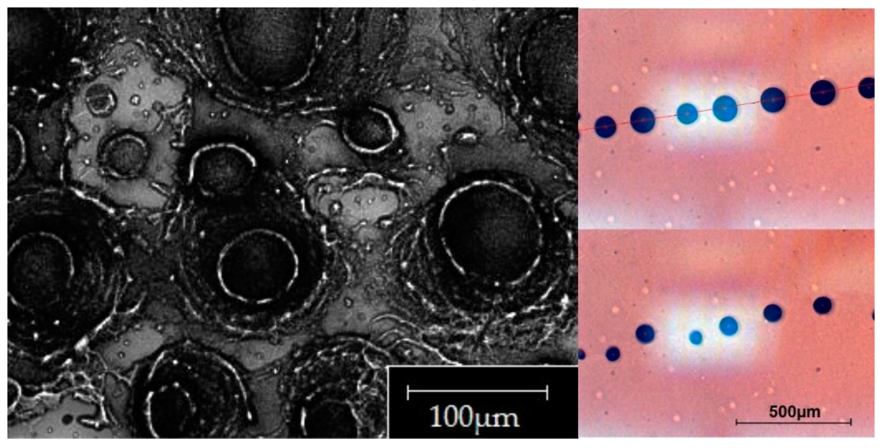
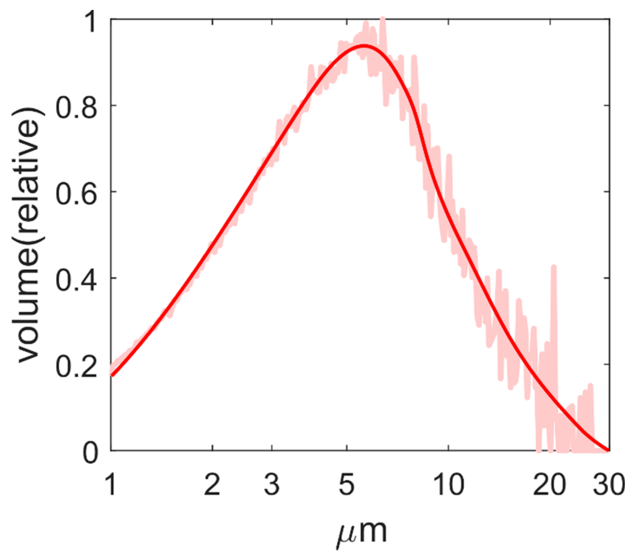
To better understand the deposition pattern of the PM contained in a liquid solution deposited with a Microdrop dispenser, we prepared a suspension consisting in high purity water (MilliQ technology) and a given amount (50 µg/mL) of a reference material: the NIST standard 2709a. The latter is a well-known soil reference material with a well-characterized composition [
11] and grain size distribution. To avoid the clog of the Microdrop nozzle, we selected a reference material whose particles didn’t exceed 30 μm, i.e., about the half of the aperture of the nozzle orifice, as shown in
Figure 5.
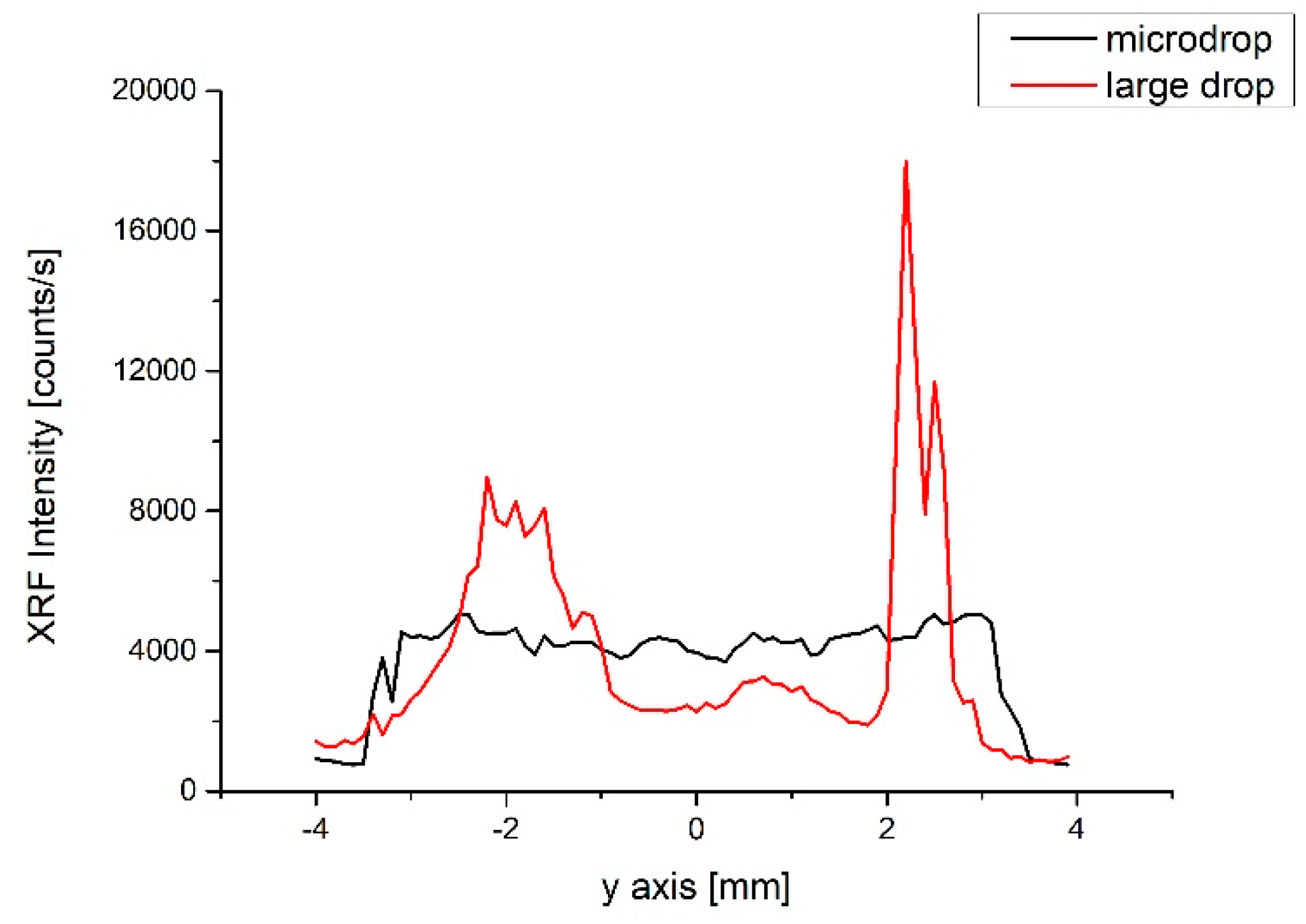
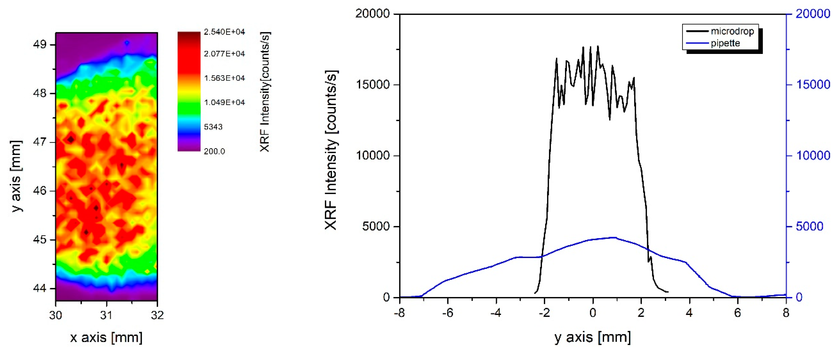
Since the standard contains Fe, it was possible to use the X-ray fluorescence (XRF) technique to investigate its spatial distribution after deposition. In
Figure 6, we compare two XRF profiles collected on two deposited samples, measured along a straight line, with a spatial resolution limited by the spot size of the beam (~200 µm). The red curve is the profile relative to the deposition of a single large drop of ~1 mL volume of the NIST solution. The black curve refers to a deposition obtained with the microdrop, made by multiple patterns of 240 µm diameter droplets with 170 µm between them. The same total volume and the same solution were considered. The two profiles show significant differences and it is remarkable that the homogeneous deposition was obtained with the latter technique, despite the reduced amount of solution. Indeed, the large drop shows density fluctuations from 50% to 80% of the fluorescence intensity, in particular at the edge due to the coffee-stain effect [
1]. At variance, the variability observed along the microdrop profile is around 10%, and the deposited soil is uniformly distributed.
Figure 6 compares a microdrop deposition, which clearly shows the homogeneity and the overall quality of the samples prepared with the microdrop increase. The only disadvantage of this method is the deposition time. Indeed, as it can be inferred from
Figure 4, the optimal configuration of this micro-deposition allows us to deposit and to evaporate liquid samples with a rate of less than 1 mL per hour. A simple and alternative way to reduce the deposition time can be obtained by combining the microdrop deposition with a simultaneous filtering technique. In this way, the droplet is deposited onto a wettable filter, and the liquid is pumped out by a vacuum pump.
In
Figure 7 (left), the 2 × 5 mm
2 image shows a portion of the original 4 × 4 mm
2 microdrop deposition area of 1 mL NIST solution (50 µg/mL concentration) on a polycarbonate Nucleopore© membrane filter (pore size 0.45 μm and filter area diameter ~20 mm), which is a hydrophilic substrate. This type of substrate absorbs the liquid solution, and the liquid is continuously pumped out through the filter. The color map was obtained collecting the XRF signal at the Fe K-edge. Colors highlight an area of approximately 2 × 3 mm
2 where a controlled distribution is achieved. The internal variability is probably also related to the spatial pattern of the pores characterizing the filtration membrane.
In
Figure 7 (right), one microdrop deposition profile of the image on the left is compared with an analogous profile of the deposition of the same solution using a micro-pipette on the same type of filter. From the analysis of the data, we may point out that by using the microdrop deposition, ~80% of the material is distributed quite homogeneously (with a fluorescence intensity fluctuation of ~15%) inside an area of ~8 mm
2. Using the pipette deposition, the same amount of material is deposited within an area six times larger (~50 mm
2). A simple evaluation points out that the microdrop filtration procedure covers an area 6.25 times smaller than the area wetted with the pipette, but the intensity of the fluorescence signal, proportional to the deposed material is four times higher. In this case, the total gain we achieved is ~25.
4. Conclusions
The microdrop technology is suitable to prepare homogeneous deposition of particulate and granular matter samples. In order to establish a reliable procedure, reducing also the deposition time, it is necessary to measure accurately the evaporation rate of the pattern depositions. We show here how to optimize such parameters, increasing the S/N ratio and the deposition homogeneity, reducing at the same time the sample consumption. Indeed, S/N ratio is related to the XRF signal; increasing the density and the homogeneity of the deposition, the S/N ratio of the XRF signal that outlines the distribution of the material in the sample improves. In terms of deposition uniformity, with the microdrop technique, the S/N ratio may improve ~4 times with respect to a classical filtration method. At the same time, it is possible to deposit and evaporate a solution onto any substrate and 5 times more homogeneously than a large drop evaporation. These features make this technique effective and competitive with respect to many and diverse applications. Among the many, we cite the characterization of aerosols for pollution monitoring purposes, studies of metallic contaminants in polluted water or the investigation of biological diluted materials at ultra-trace concentrations. Besides homogeneity, another important feature of the method proposed here, is the possibility to concentrate in a very reduced area the material contained in an extremely diluted solution or suspension. This makes it possible to consider impurities whose concentrations span from few ppb to hundreds ppm. As an example, the method is suited for the characterization of the inorganic insoluble particulate matter contained in ice core samples for paleoclimatic reconstructions. Ice core dust samples prepared with a microdrop device could be successfully used for both X-rays absorption and X-ray fluorescence measurements [
13,
14] and under particular experimental conditions also for XRD experiments [
15]. Certainly, the microdrop technique has to be improved for applications where beams with spot size well below one micron will be available, as to ultra low brilliance synchrotron radiation facilities and/or Free Electron Lasers. However, due to the low frequency rate of the existing Free Electron Lasers (10–100 Hz), the technique could already be useful to control the deposition of small samples such as small crystals, clusters, or organic systems delivered to the beam inside droplets.

 ,
, 