
Model for Rating a Vanadium Redox Flow Battery Stack through Constant Power Charge–Discharge Characterization


Department of Chemical Engineering, Indian Institute of Technology Madras, Chennai 600036, India
*
Author to whom correspondence should be addressed.
Batteries 2022, 8(8), 85; https://doi.org/10.3390/batteries8080085
Submission received: 5 July 2022
/
Revised: 27 July 2022
/
Accepted: 2 August 2022
/
Published: 9 August 2022
(This article belongs to the Collection Recent Advances in Battery Management Systems)
Abstract
:A method for estimating the stack rating of vanadium redox flow batteries (VRFBs) through constant power characterization was developed. A stack of 22 cells, each with 1500 cm2 of nominal electrode area, was constructed and tested using constant current and constant power protocols. Typical ratios of charging to discharging power that prevail in various applications (e.g., peak shaving, wind power/solar photovoltaic power integration) were employed in the test protocols. The results showed that fractional energy storage capacity utilization and round-trip energy efficiency varied linearly with the power at which the energy was charged or discharged. A zero-dimensional electrochemical model was proposed based on the area-specific resistance to account for the energy stored/extracted during constant power discharge in the state of charge (SoC) window of 20% to 80%. It was shown that this could be used to rate a given stack in terms of charging and discharging power from the point of view of its application as a power unit. The proposed method enables stack rating based on a single polarization test and can be extended to flow battery systems in general.
1. Introduction
Growing energy demand and the need for drastic reductions in greenhouse gas emissions compel the world to move toward renewable energy sources. For utility-scale applications, wind farms and solar photovoltaic (PV) farms have emerged in recent years as popular alternatives to replace fossil-fuel-based power generation. However, both power sources are highly intermittent and do not have sufficient energy storage capacity to provide power on and as per demand. The integration of renewable power availability with consumer power demand poses considerable challenges, as the power generated in these devices depends on solar irradiation and wind speed, which prevents the usage of these sources round the clock [1]. The speed of the wind determines the energy extracted from the wind farm, which fluctuates randomly within short durations [2]. In addition to instantaneous fluctuations, there can be long-range variations. For instance, the seven-day PV profile created by Parameswarappa et al. [3] exhibited considerable day-to-day variation in solar power insolation. In many places (e.g., most of India), wind energy exhibits large seasonal variation [4]; the integration of multiple power sources is mandatory to match the power availability with the power demand in grid-scale power systems. Electrochemical storage devices, such as batteries, offer excellent integration prospects, as their response time is very short, and they can switch modes instantly from charging to discharging and vice versa. Redox flow batteries, with their scalability, long life, and independent scaling of power and energy [5,6,7], are emerging as strong contenders for utility-scale energy storage applications. Although several redox flow batteries have been developed to date, vanadium redox flow batteries (VRFBs) have gained considerable scientific and commercial traction. Since the same redox species are present on both sides of a VRFB cell, there is significantly less cross-contamination than in the other flow batteries [8]. As shown in Table 1, VRFB is less costly for given energy requirements compared with other matured redox flow battery technologies [9].
It is optimal to run a utility-scale electrical power plant continuously at its rated condition while supplying electricity as needed by customers. For these plants, leveling the demand peaks (also known as “peak-shaving”) is of utmost importance. Harnessing variable power availability from renewable energy sources also calls for the development of effective energy storage systems (ESS). For peak-shaving applications, the ESS has to charge at times of low demand and discharge briefly during periods of high demand. In contrast, charging occurs at high power and over a short duration, while discharge takes place over a lengthy time in a solar PV system that is integrated with a domestic load [3]. Thus, the charging-to-discharging power of an ESS is highly dependent on the application.
Since their invention, numerous studies have been carried out on different aspects of VRFBs, such as flow fields, electrodes, membranes, and integration with renewable energy sources [10]. Industrial-scale VRFB stack studies were carried out on performance characteristics, design considerations, and shunt current losses. Ma et al. [11] investigated the impact of flow rate on a kW-scale VRFB stack and found that at a high flow rate of 0.71 m3/h, the system efficiency increased by 8%. Zhao et al. [12] constructed and tested a 1 kW stack consisting of 14 cells of 875 cm2 active area and reported average power output of 1.14 kW at a current density of 70 mA/cm2. They also constructed a 10 kW stack by connecting the 1 kW units in series and showed an 82.35% energy efficiency (EE) at 50 mA/cm2. Kim et al. [13] tested the performance of a 1 kW/1 kWh VRFB stack with mixed acid solutions and reported a round-trip energy efficiency (EE) of 82% and a power output of 1.2 kW at 80 mA/cm2. Park et al. [14] showed testing of a kW-scale stack of 31 cells with a 2714 cm2 active area and reported EEs of 76% and 70% at operating current density of 60 and 90 mA/cm2, respectively. Gundlapalli and Jayanti [15] studied three kW-scale stack configurations with different cell areas to bring out the effect of cell size on stack efficiency.
Stack testing and characterization have recently been receiving increasing attention. Short-term cycling and the effect of flow rate were studied on a 9 kW/26 kWh industrial-scale VRFB stack by Guarnieri et al. [16,17]. Several modeling studies were also reported to determine the electrochemical performance of the VRFB cell with respect to current density, flow rate, porosity, etc. [18,19,20,21,22,23,24]. You et al. [19] proposed a simple model by considering all three overpotentials and showed good agreement between the experiments and model at different current densities and compressions. An accurate model for OCV measurement of the VRFB cell was proposed by Knehr et al. [20], which was in accordance with experimental OCV values. In order to determine the optimal electrolyte circulation for a VRFB system, Tang et al. [25] studied the effect of flow rate on both the concentration overpotential and pressure losses. Pugach et al. [26] proposed a zero-dimensional model that mainly focused on the vanadium ion crossover, leading to capacity decay through corresponding governing equations. They also proposed a model [27] to estimate the critical parameters of a commercial kW-scale VRFB stack by only considering stack and tank sizes.
The idea of battery characterization at constant current density is consistent with the conventional view of a battery as an electrochemical process in which the battery voltage depends on the overpotential, which itself is directly related to the current density. Typically, the battery performance needs to be studied over the entire operating range of the state of charge (SoC). However, in the case of a flow battery, constant current density operation does not equate to constant power output because the open-circuit voltage (OCV) varies significantly across a charge or discharge cycle (unlike in the case of a lead–acid battery or a lithium-ion battery). As a result, the cell voltage also changes during charge–discharge cycling. For a given amount of power, the battery current will be lower at high SoCs (i.e., at the end of a charging cycle) than at low SoCs (toward the beginning of the charging cycle). Because concentration polarization frequently limits the discharge capacity of large flow batteries, the battery current will be particularly high for low SoCs in the case of discharging. The amount of energy that can be drawn from a battery depends on how much power is needed, and constant power cycling effectively captures this. Even though the power rating of the stack is often associated [16] with the peak power obtained in polarization studies, it is not a true reflection of the stack rating because a short-duration test may not reflect the ability to charge or discharge a large fraction of the storable energy at that power. In practical applications, the energy that can be extracted is as equally important as the power at which the energy can be transferred.
Against this background, the present paper proposes an approach for stack rating based on constant power testing. Although a flow battery has the benefit of decoupled power and energy ratings, the rated energy cannot be transferred if energy is extracted or put in at very high power. Operating a given stack at high power leads to high energy losses, reducing the charging or discharging time. High overpotentials associated with high power operation may limit energy exchange due to constraints on the voltage limits of operation of the stack. The present study was aimed at understanding the extent of these energy losses quantitatively. To this end, we report on constant power testing of a 5 kW VRFB stack at various charging and discharging powers. Based on the obtained results, a simple model was proposed for stack rating that uses only one constant power characterization to arrive at the power rating of the stack for charging and discharging.
2. Materials and Methods
2.1. Experimental Section
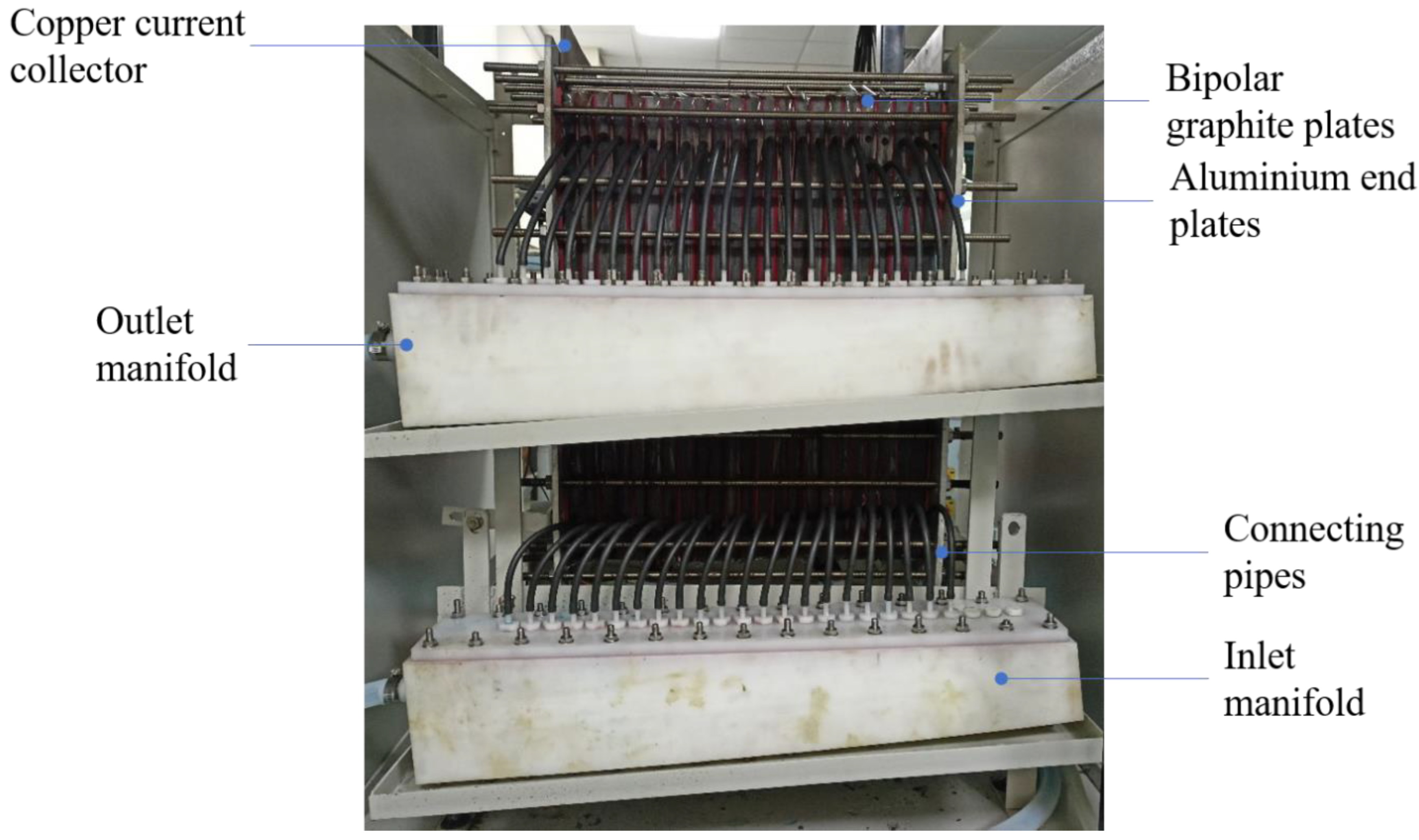
The VRFB stack shown in Figure 1 has 22 cells, with each cell having a nominal electrode area of 1500 cm2 active area. It was built in the same way as the 8-cell stack reported previously in [15]. Activated graphitized carbon felt of 4.6 mm thickness, which was procured from SGL Ltd., was used as an electrode, and an untreated Nafion 117 membrane, which was soaked in de-ionized water for 24 h, was used to serve as the proton conductor and separator of the positive and negative electrolytes. The carbon felt electrode was cut into an active area size of 1500 cm2 and was placed over a serpentine flow field that was grooved into 15 mm-thick graphite plates. The membrane was sandwiched between two such graphite plates to form a cell, and the leakage and mixing of electrolytes were prevented by using silicone gaskets. Twenty-two such cells were stacked in series between two current collector plates that were 2 mm thick and two aluminum end plates that were 10 mm thick. The cells were carefully fastened together using nuts and bolts to maintain proper electrical contact and to eliminate electrolyte leakage. Figure 1 shows the stack connected to external manifolds for electrolyte supply to each cell. The manifolds that were connected to their respective electrolyte tanks via peristaltic pumps were used to circulate electrolytes at the desired rate. Vanadium salt was dissolved in a 5 M H2SO4 solution to make a 1.6 M VOSO4 electrolyte. Other redox species (V5+, V3+, and V2+) were generated in the dissolved form using the dual step charging approach [15]. A total of 35 L of the electrolyte were used in all studies, both on the positive and negative sides. In order to prevent the oxidation of the electroactive species, the negative-side electrolyte was continually purged with nitrogen. Electrochemical characterization was carried out using a Bitrode battery cycler with a 72 V and 200 A maximum voltage and current range, respectively. All the tests were conducted with an upper voltage limit of 37.4 V while charging and a lower voltage limit of 17.4 V while discharging. During testing, cell-to-cell voltage variations, which were measured using a hand-held multimeter, were found to be small (typically within 0.05 V).
Constant-power charge–discharge cycle tests were carried out at different power ratios, as well as for different combinations of charging and discharging powers. Power ratio is defined as the ratio of the charging power to the discharging power. All the tests were conducted at a flow rate of either 6 Lmin if the operating power was less than 3 kW or at 8 L/min for an operating power equal to or higher than 3 kW. Four charge–discharge cycles were performed for each power combination, and the mean of the final two cycles was utilized to gauge the stack performance. Prior to doing these charge–discharge cycle studies, polarization tests [28] were conducted in which the stack, after slow initial charging, was discharged in short intervals (45 s) of constant current, which was increased in steps from 20 mA/cm2 to as high as achievable. Each current step was preceded by a rest period of 1 min, during which there was no current drawn from the stack to allow it to reach its OCV value.
2.2. Model Construction
The stack power rating model was developed as follows. Consider stack operation at high powers, as shown schematically in Figure 2, in the form of stack voltage plotted against the state of charge (SoC), which is proportional to the charging capacity of the system. Although the deep discharge of VRFB is possible, one can consider the SoC range of [5%, 95%] to be safe. The maximum total theoretical energy that may be stored in and retrieved from the system is represented by the area under the curve that is bounded on the upper side by the open-circuit voltage (OCV) and on the left and right sides by the lower and upper limiting values of SoC. For a given stack power operated in discharge mode in the SoC range of [20% to 80%], a typical stack voltage will be less than the OCV due to various overpotentials. The energy delivered will thus be less than the theoretical maximum. In the present work, we use the relation between the operating power and the delivered energy relative to the theoretical maximum to arrive at the criterion for the power rating of the stack. This is based on a simple model, which was constructed using the findings of polarization investigations to estimate the relationship between the cell overpotential and the operating parameters, such as the operating power (P), temperature (T), and state of charge (SoC), subject to the following assumptions:
- The VRFB system is operated primarily in the SoC range of 20 to 80% under normal conditions to maintain the electrolyte in good condition by preventing the occurrence of side reactions. Under these conditions, it is expected that no irreversible damage occurs to the electrolyte due to crossover.
- The range of operation of the battery is limited by the SoC and not by voltage limits. This is justified for the limited purposes of the present model for the stack rating in which the rated power is expected to be much less than the peak power obtained from a short duration test.
- Concentration overpotential can be neglected when considering cell overpotential. This possibility arises from the first two assumptions, which are likely to keep the system sufficiently far from the point where mass transfer limits the performance of the stack.
- Over the 20 to 80% SoC range, the overpotential can be expected to vary primarily as a function of the current density and is a weak function of the SoC in this range. This assumption is justified based on empirical observations from the present data (see below), as well as stack data from the literature [29].
In the model, the open-circuit potential (OCV) of the cell is calculated from the following relation from the initial SoC of the electrolyte.
where:
;
;
;
;
.
The actual voltage of the cell is obtained from the addition (subtraction) of the overpotential (η) to the OCV:
where:
;
.
Here, denotes charging and discharging, respectively. The voltage calculated from Equation (2) was for a single-cell potential. The overall stack voltage was calculated by multiplying by the number of cells (Nc). The area-specific resistance needed to determine the overpotential was found from the linear relation of current density extracted from the polarization data. Different predictions were carried out based on the constructed model regarding the SoC variations.
3. Results and Discussion
3.1. Polarization Curve
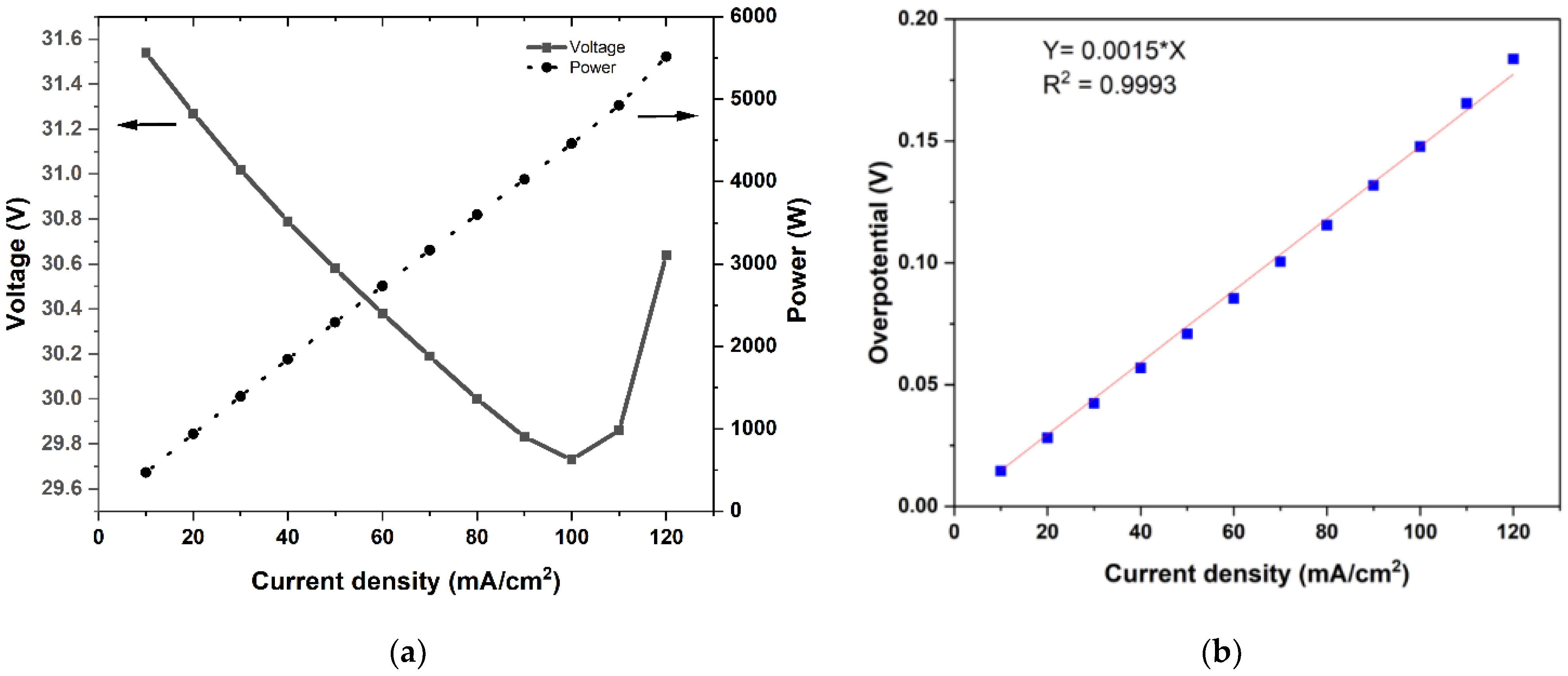
Polarization studies were carried out through short-duration discharge pulses of 45 s each from 120 mA/cm2 to 10 mA/cm2 while maintaining a constant electrolyte rate of 8 L/min. Figure 3a depicts the influence of the current density on the stack voltage and power, which were averaged over 45 s at each current density. One can see that the delivered power was 5.6 kW at the current density of 120 mA/cm2 and decreased nearly linearly with the current density. The variation of the stack voltage (over the narrow range shown in the figure) was slightly complicated by two competing factors: decreasing tendency due to decreasing SoC and increasing tendency due to the reduced overpotential due to the decreasing current density. The test was conducted with a progressively decreasing current density, and therefore, the curves in Figure 3a should be read from left to right. At high powers, the decrease in SoC per current step was high, and the stack voltage decreased. As the power was reduced, the overpotential was also reduced, leading to an increase in the stack voltage. This effect compensated for the voltage decrease due to the SoC decrease in that current pulse. As a result, the stack voltage kept increasing as the test progressed from high-power pulses to low-power pulses.
Every discharge pulse in the test method featured an OCV measurement step, which allowed for the determination of the total overpotential in relation to the imposed current density. The polarization curve obtained in this manner is shown in Figure 3b. It was evident that, over the range of test conditions (current density in the range of 20 to 120 mA/cm2 and estimated SoC in the range of 30% to 65%), the overpotential increased linearly with current density. This was consistent with literature observations [12,29,30]. A linear fit passing to the data gave the area-specific resistance, namely, a in Equation (3), to be 0.00148 ohm-cm2. This value is consistent with other reported literature data for stacks [15,16].
3.2. Constant Power Charge–Discharge Cycles
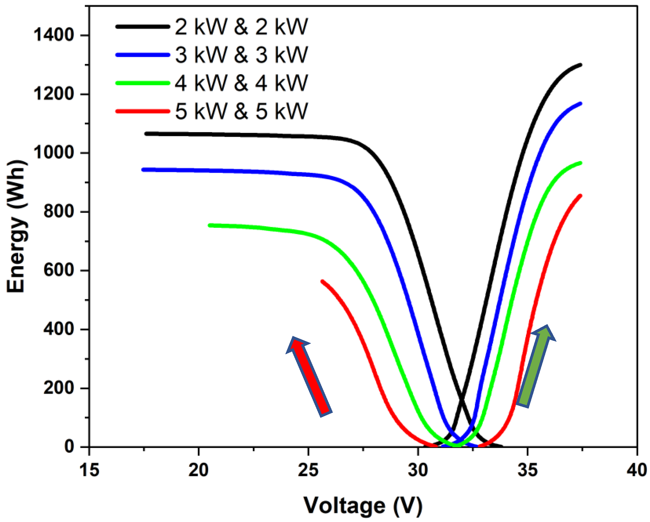
Constant-power charge–discharge cycling was performed using different power combinations for charging and discharging. Different power ratios (charge power (Pch) to discharge power (Pd)) were employed to study the constant-power charge–discharge characteristics. Typical plots of energy vs. stack voltage for different charging and discharging powers are shown in Figure 4. Here, the green arrow represents the progression of the charging phase, and the red arrow represents the progression of the discharging phase. Each curve had a linear section preceded and followed by a non-linear section. The linear section corresponded to the mid-SoC region in which the overall polarization was dominated by an effective ohmic overpotential. The last section with highly non-linear variation with a steep voltage drop in the discharge phase corresponded to the case where the cell potential was influenced by mass transfer limitations. Since the stack was operated within fixed upper and lower voltage limits, the concentration polarization region was not as clearly marked during the charging phase. When the operating power increases, the current density and the overall overpotential increase, and the charging or discharging may stop before reaching the mass-transfer-limited section. This can be seen to be the case for the 5 kW discharge. One can also observe that as the power was increased, less energy was charged or discharged and that more power was used during charging than during discharging, which lowered the round-trip energy efficiency. It may be noted that the energy utilized for charging was the sum of the stored energy (corresponding to the area under the OCV curve in Figure 3) and the energy spent in maintaining the charging overpotential. Similarly, the energy delivered during a discharge was equal to the difference between the energy that was stored and the energy that was used to keep the essential overpotential when discharging. The round-trip energy efficiency was thus a reflection of the overpotential that was required to be maintained while charging and discharging as per a protocol. The higher the power, the higher the losses and the lesser the recoverable energy used for charging. In the present work, this was used to arrive at a rating of the stack.
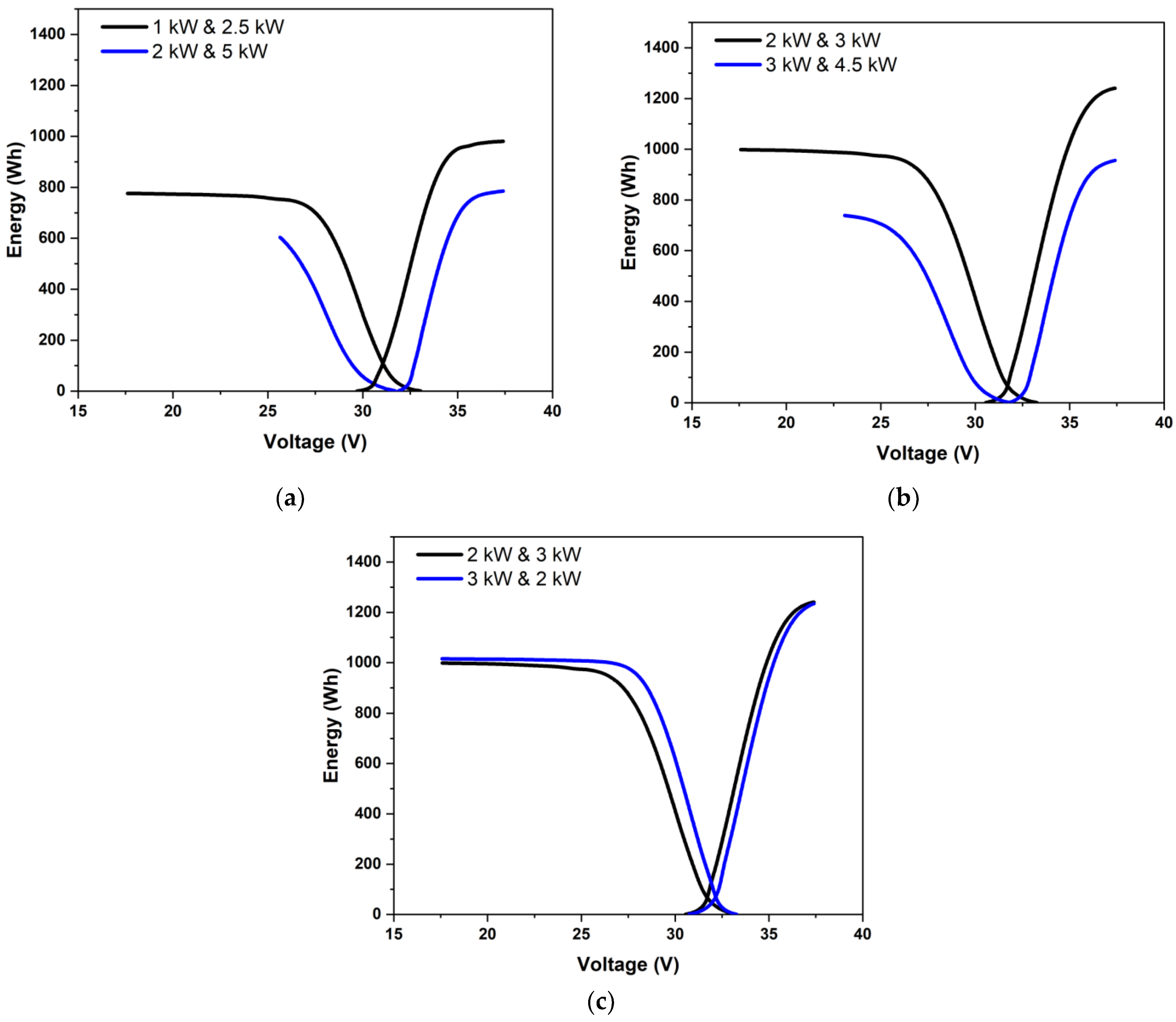
The overpotentials may vary greatly depending on which is higher in a scenario of unequal charging and discharging powers. Three cases of unequal powers are shown in Figure 5. Figure 5a shows the case where the charging and discharging powers were in the ratio of 0.4. The energy vs. voltage variation is shown for two cases: one for charging to discharging powers of 1 kW to 2.5 kW and another for 2 kW/5 kW, with both having the same overall ratio of 0.4 with high discharge power. Figure 5b shows the results for charging to discharging powers of 3 kW to 2 kW and 4.5 kW to 3 kW, with both being in the ratio of 1.5 with high charging power. Figure 5c compares the results for the cases with charging to discharging powers of 2 kW to 3 kW and 3 kW to 2 kW, i.e., power ratios of 2:3 and 3:2. When the charging power was low (as in Figure 5a), one can see a clearly marked charging mass-transfer-limited section. Further, due to low charging power, a higher SoC change could be effected, and a higher amount of energy could be delivered during discharge. For the same power ratio with the considerably higher discharge power of 5 kW, the discharge had to be stopped due to voltage limits even before the onset of the mass transfer limitation. The amount of energy that could be delivered was, therefore, noticeably less than under low power operation. Under moderate powers, as in Figure 5c, the round-trip energy efficiency was not significantly affected by charging and discharging powers as long as they were the same. According to Figure 5c, high charging power was marginally preferable to high discharging power. This was because, under constant power conditions, the charging current density was lower than the discharging current density due to the greater cell voltage during charging.
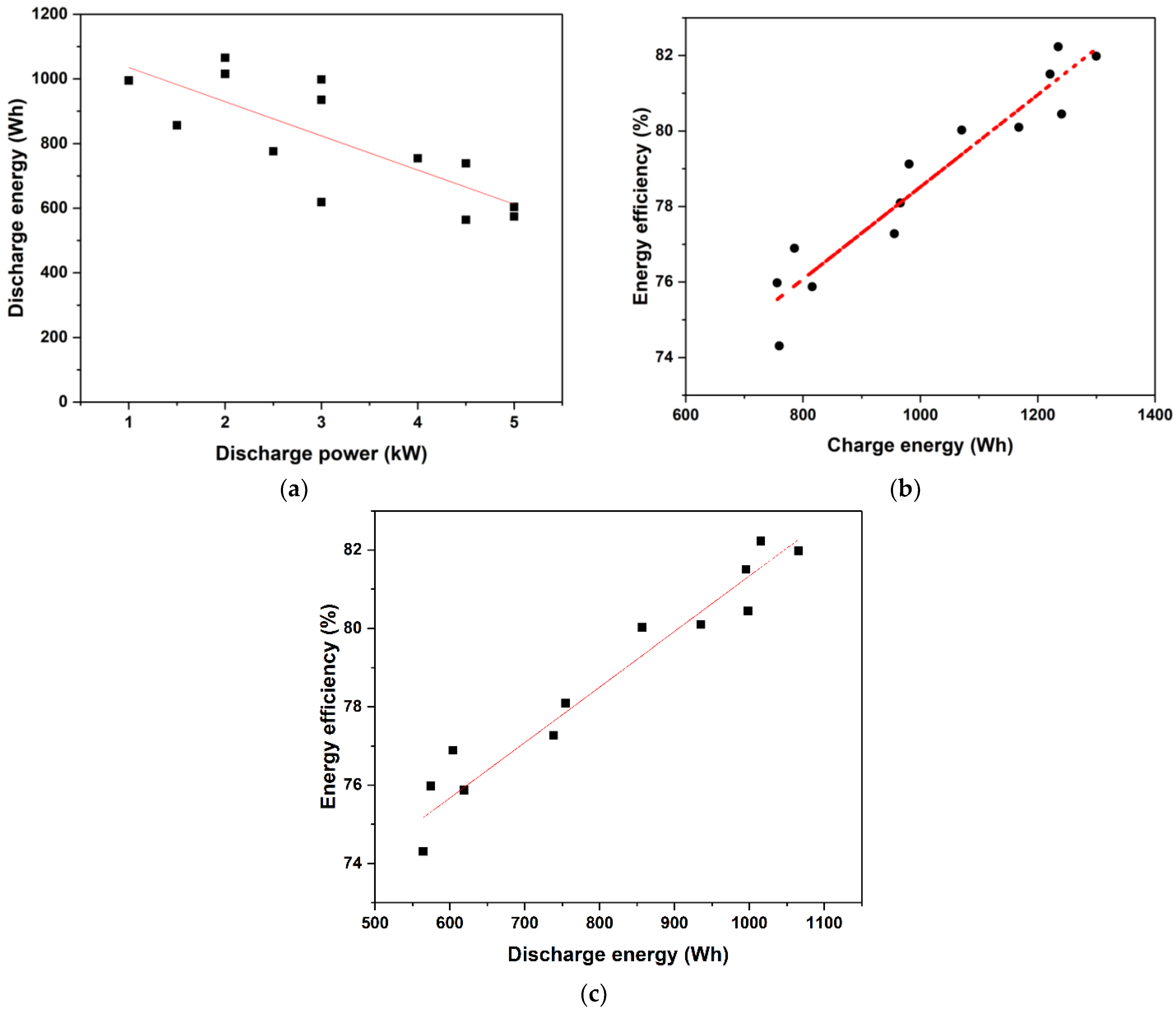
Figure 6a represents the variation in discharge energy as a function of power for both equal and uneven charging and discharging settings. The capacity to discharge energy was shown to decrease practically linearly with power. In Figure 6b, the round-trip energy efficiency is plotted versus charged energy for the various powers and power ratios investigated in the present study. One can see that in all the cases, despite the widely ranging charging and discharging powers, the efficiency was moderate fairly high and varied in the range of 75% to 83%. Within this small range, a nearly linear variation of energy efficiency with charged energy was found, showing that the charging power had a minor effect. A similar trend was observed for the dependence of the round-trip energy efficiency on the discharge energy, as shown in Figure 6c. All the data put together showed that reasonably high round-trip energy efficiencies (~75% or higher) were achieved for stack powers of up to 5 kW with this stack.
3.3. Model Predictions
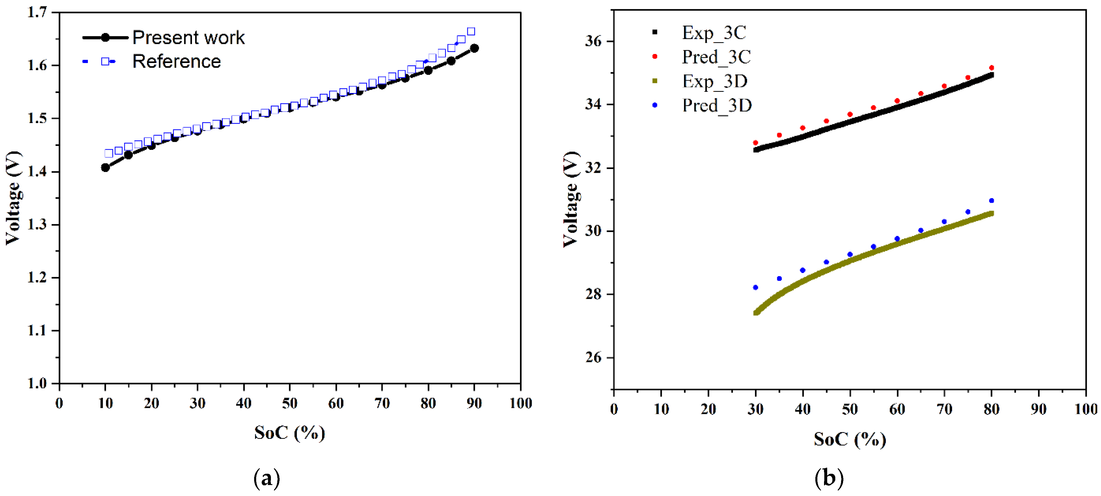
The overpotential relation extracted from the polarization is given by Equation (3), with the coefficient representing the area-specific resistance, which had a value of 0.00148 ohm-cm2. The accuracy of the model can be gauged from Figure 7a, where the comparison with literature predictions from a more comprehensive overpotential model [19] is given for the case of a cell operating at a current density of 80 mA/cm2. It can be seen that there was a good agreement for the variation of the cell voltage during charging over the SoC range of 10% to 90%. Figure 7b shows a comparison with present experimental data of the present model predictions of the stack voltage variation with respect to the SoC during charging and discharging at a constant power of 3 kW. The experimental data were recorded as a function of time; these were converted to an SoC as follows [22]:
where:
;
;
.
Stack voltage experimental data and model predictions were in good accordance over a wide range of SoCs despite the fact that the experiments were conducted with voltage limitations. This model was used to arrive at a protocol for the power rating of a stack, as discussed in the next section.
Figure 7.
Predictions of the present model: (a) comparison of the cell voltage variation with SoC at a current density of 80 mA/cm2 with the predictions of a more comprehensive overpotential model [19], and (b) a comparison of the predicted voltage variation with respect to SoC during charging and discharging at 3 kW with data from the present experiments.

4. Stack Rating
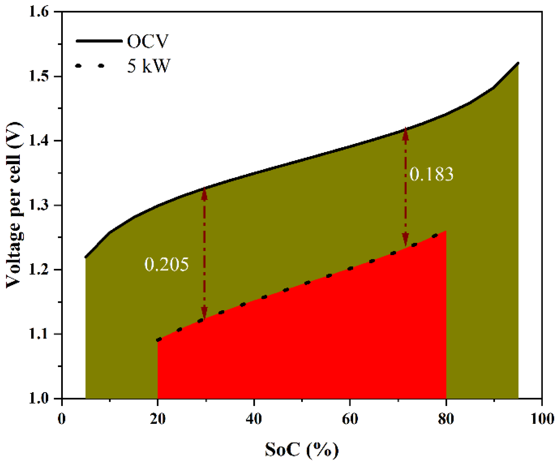
The voltage variation over an SoC range gives information about the energy losses during the charge–discharge operation. The area under the curve (AUC) of an OCV vs. SoC (i.e.,, where Eo is the OCV, S is the SoC, and SL and SU are the lower and the upper limits of the SoC) indicates the maximum extractable energy from the stack over an SoC range. Figure 8a shows the predicted OCV variation of the cell over the SoC range of [5%, 95%] and the predicted variation of the voltage per cell during discharge of the stack at a constant power of 5 kW over the SoC range of [20%, 80%], which can be considered as the normal (design-basis) variation of a VRFB system. Since the voltage decreased as the SoC decreased during discharging, the overpotential, even though it was proportional to the current density, was higher by about 10% toward the end of the discharging (SoC ~20%) compared with that at the beginning of discharging (SoC ~80%). The energy delivered during discharging is the area under the cell voltage curve, i.e., , where V is the voltage of the cell. Figure 8b schematically compares the energy delivered by the stack under different constant power discharges over the SoC range of [20%, 80%]. The theoretical maximum energy, correct to a multiplicative constant, was 0.822 over the SoC range of [20%, 80%]. During a 2 kW discharge, the energy delivered was 0.780, denoting a discharge energy loss of 5.1% of the theoretical maximum. At 5 kW, the energy delivered was only 0.706, indicating a much higher discharge energy loss of 14.1%. This can be generalized to any power and for any charging or discharging protocol.
Under the assumptions made in the present model (of battery operation in the SoC interval where effective ohmic overpotential determines its polarization curve), knowing the area-specific resistance of the stack and the OCV variation with the SoC of a (vanadium) flow battery, one can compute the energy delivered (or used during charging) as a function of power. For the present battery, the computed energy loss during constant power charge or discharge is shown in Figure 9 as a function of power. It can be seen that the variation was nearly linear, and that the energy loss was higher under constant power discharge, as expected (due to lower stack voltage) for the same power. If one were to take 10% loss as reasonable energy loss in charging and discharging (giving a round-trip energy efficiency of 81.8%) within the SoC range of [20% to 80%], then the stack power could be rated to be 3.9 kW under discharging and 4.7 kW under charging (see Figure 9). Under these conditions, the energy utilization of the battery will be 81.8% of the 80% to 20% SoC range or 60% of the theoretical maximum or close to 49% of the theoretical maximum energy storage capacity based on the amount of the electrolyte and concentration of the active species. Thus, the proposed power rating based on 10% energy loss in each of the charging and discharging phases would lead to nearly 50% capacity utilization and can be considered an effective utilization of the storage capacity.
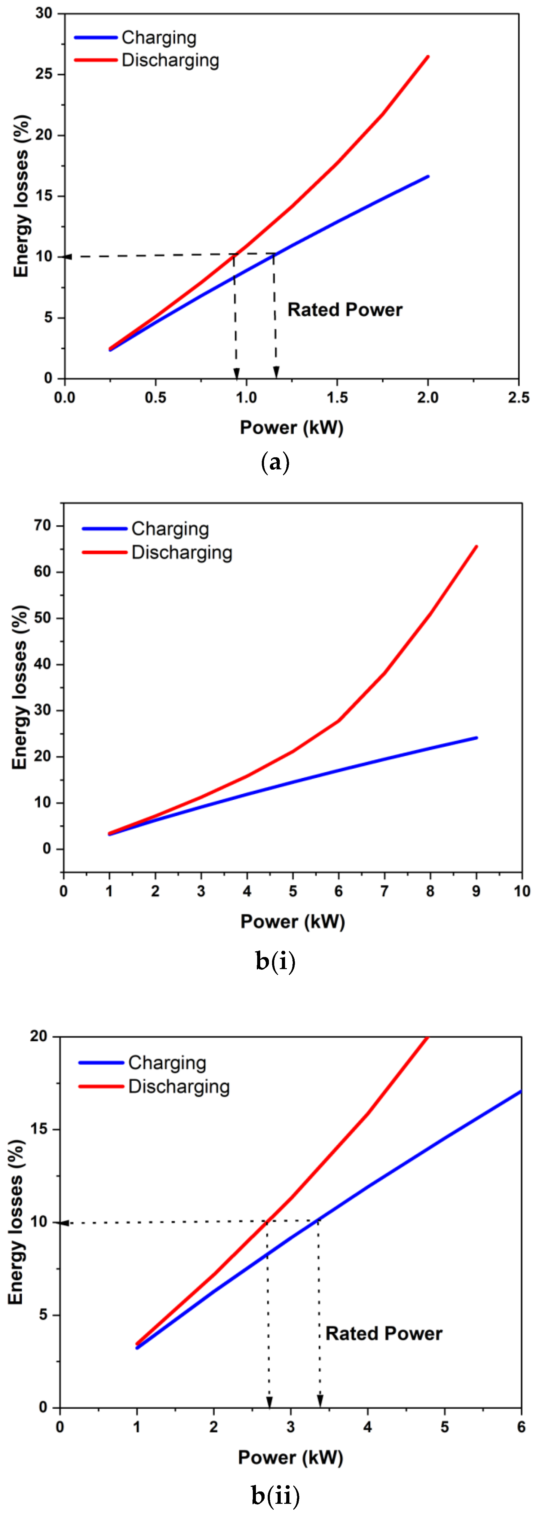
Figure 10 shows the application of the proposed power rating concept to two stacks from the literature. Figure 10a shows the estimated energy loss during charging and discharging for the nominal 1 kW stack of Zhao et al. [12]. The area-specific resistance estimated for this stack from their reported data was 0.0023 ohm-cm2. Applying the 10% loss per operation criterion gives the stack a power rating of 0.9 kW during discharging and 1.35 kW during charging. Thus, the nominal 1 kW power rating for this stack is justified and is consistent with the present stack rating concept. Figure 11b shows the estimated energy losses for the 9 kW stack studied by Guarnieri et al. [16]. The estimated area-specific resistance for this stack was about 0.0017 ohm-cm2, which is close to that of our stack. Guarnieri and co-workers [16,17] reported polarization data for up to 9 kW during charging for this and, therefore, claimed this be capable of operating at up to 9 kW. However, as shown in Figure 10(b(i),b(ii)), the predicted energy losses for 9 kW constant power operation are quite considerable (>60% under discharge alone). If it was run at 9 kW, the round trip energy efficiency would be pretty poor (~12%). It is also unlikely to have been able to utilize a significant amount of storage capacity. As per the present 10% energy loss criterion during each process, the stack should be rated at only 2.65 kW during discharging and 3.45 kW during constant-power charging. It may be noted that this stack was originally rated at 4 kW [16], which is closer to the present criterion. Thus, rated power for meaningful capacity utilization can be significantly different from the peak power that can be sustained for a short duration. The rated power was quite different from the peak power obtained in the polarization studies.
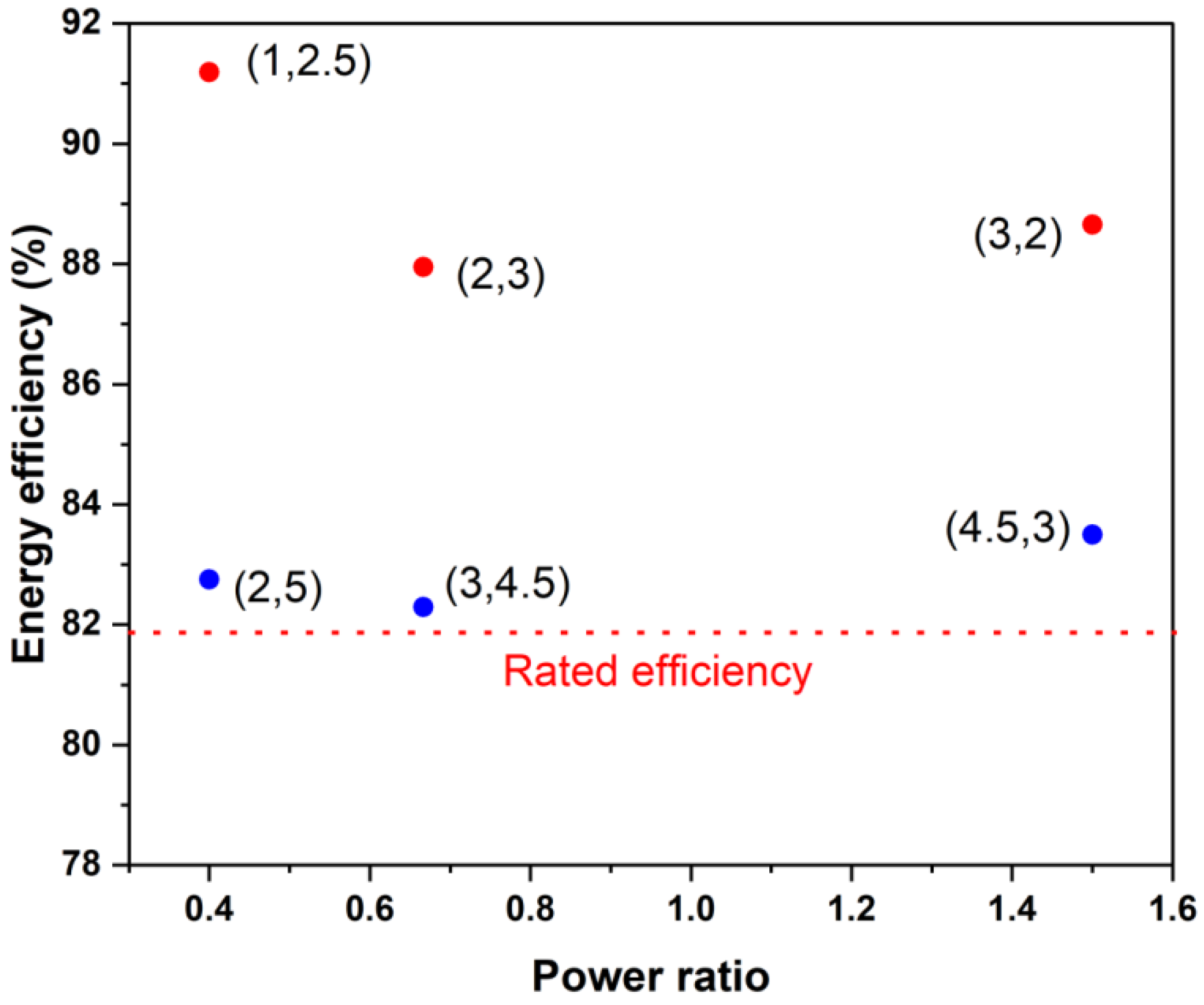
Finally, the round-trip energy efficiency of a stack of a given power rating did not depend strongly on the charging-to-discharging power ratio if the operating power is within the rated power. Figure 11 illustrates this by depicting the predicted energy efficiency of the current stack when it is used at various power levels and power ratios between 20 and 80% of the SoC. One can see that substantially higher efficiencies (>85%) can be achieved if the operating powers are about half or less of the rated charging and discharging powers. This is consistent with recently reported stack efficiency values of 88% during charging and 94% during discharging [3] for a kilowatt-scale stack, which was operated only intermittently under high power conditions.
5. Conclusions
The charge–discharge characterization of a kW-scale VRFB stack was performed by employing the constant power protocols. Different combinations of charging and discharging powers (different power ratios) were employed to investigate the energy exchange characteristics. Polarization studies were also conducted on a stack with a 5 kW nominal rating. The study’s findings can be stated as follows.
- It was found that the discharge energy varied linearly with varying power and that high-power operations resulted in less energy extraction due to higher overpotentials. Round-trip energy efficiencies were found to vary from 75% to 82%, which depended primarily on the power rather than on the power ratio.
- It was observed that the stack overpotential was a strong function of the current density in the healthy SoC range (30–80%) and was governed by an effective ohmic potential type of variation. The area-specific resistance in this SoC range was estimated to be 1.48 mΩ-cm2.
- A protocol was developed for determining the power rating of a stack based on the anticipated energy losses when the stack is run at constant power over the SoC range of 20 to 80%. It was found that using 10% energy loss in each charging and discharging process led to a reasonable power rating of the stack, as well as reasonably high capacity utilization of the electrolyte while maintaining a stack round-trip energy efficiency of over 80% (without counting pumping and other auxiliary losses).
- The power rating of the stack using the proposed criterion gave different power ratings under charging and discharging conditions. Operation under different power ratios did not strongly influence the energy efficiency if the operating power was about the same or lower than the rated power.
Finally, it may be noted that the proposed stack power rating concept only required the information of (i) the area-specific resistance of a well-designed stack over the SoC interval [20%, 80%], which can be obtained through a polarization test, and (ii) the OCV variation with respect to SoC for the electrolyte. Although this was derived and demonstrated for a VRFB system with a specific electrolyte composition, if the above information is available, then the stack rating concept can be used for any other VRFB system and can also be extended to other flow battery systems.
Author Contributions
Conceptualization, S.J., P.K.V. and R.C.; methodology, S.J. and P.K.V.; formal analysis, P.K.V.; investigation, P.K.V.; resources, S.J. and R.C.; data curation, P.K.V.; writing—original draft preparation, P.K.V.; writing—review and editing, S.J. and R.C.; supervision, S.J.; funding acquisition, S.J. and R.C. All authors read and agreed to the published version of the manuscript.
Funding
This research was funded by the Department of Science and Technology (DST) (grant reference no. DST/TMD/SERI/HUB/1(C)) and the Ministry of Education (MoE) (grant reference no. F.NO.41-2/2015-T.S.-I (Pt.)).
Institutional Review Board Statement
Not applicable.
Informed Consent Statement
Not applicable.
Data Availability Statement
Not applicable.
Acknowledgments
The authors would like to acknowledge the Department of Science and Technology (DST) and the Ministry of Education (MoE) for their financial support.
Conflicts of Interest
The authors declare no conflict of interest.
References
- López-Vizcaíno, R.; Mena, E.; Millán, M.; Rodrigo, M.A.; Lobato, J. Performance of a vanadium redox flow battery for the storage of electricity produced in photovoltaic solar panels. Renew. Energy 2017, 114, 1123–1133. [Google Scholar] [CrossRef]
- Jia, H.; Fu, Y.; Zhang, Y.; He, W. Design of hybrid energy storage control system for wind farms based on flow battery and electric double-layer capacitor. In Proceedings of the 2010 Asia-Pacific Power and Energy Engineering Conference, Chengdu, China, 28–31 March 2010. [Google Scholar]
- Parmeshwarappa, P.; Gundlapalli, R.; Jayanti, S. Power and Energy Rating Considerations in Integration of Flow Battery with Solar PV and Residential Load. Batteries 2021, 7, 62. [Google Scholar] [CrossRef]
- Kumar, A.; Jayanti, S. A land-use-constrained, generation–transmission model for electricity generation through solar photovoltaic technology: A case study of south India. Clean Technol. Environ. Policy 2021, 23, 2757–2774. [Google Scholar] [CrossRef]
- Aneke, M.; Wang, M. Energy storage technologies and real life applications–A state of the art review. Appl. Energy 2016, 179, 350–377. [Google Scholar] [CrossRef] [Green Version]
- Skyllas-Kazacos, M.; Chakrabarti, M.H.; Hajimolana, S.A.; Mjalli, F.S.; Saleem, M. Progress in Flow Battery Research and Development. J. Electrochem. Soc. 2011, 158, R55. [Google Scholar] [CrossRef]
- Alotto, P.; Guarnieri, M.; Moro, F. Redox flow batteries for the storage of renewable energy: A review. Renew. Sustain. Energy Rev. 2014, 29, 325–335. [Google Scholar] [CrossRef]
- Lourenssen, K.; Williams, J.; Ahmadpour, F.; Clemmer, R.; Tasnim, S. Vanadium redox flow batteries: A comprehensive review. J. Energy Storage 2019, 25, 100844. [Google Scholar] [CrossRef]
- Ulaganathan, M.; Aravindan, V.; Yan, Q.; Madhavi, S.; Skyllas-Kazacos, M.; Lim, T.M. Recent Advancements in All-Vanadium Redox Flow Batteries. Adv. Mater. Interfaces 2016, 3, 1500309. [Google Scholar] [CrossRef]
- Wang, W.; Luo, Q.; Li, B.; Wei, X.; Li, L.; Yang, Z. Recent progress in redox flow battery research and development. Adv. Funct. Mater. 2013, 23, 970–986. [Google Scholar] [CrossRef]
- Ma, X.; Zhang, H.; Sun, C.; Zou, Y.; Zhang, T. An optimal strategy of electrolyte flow rate for vanadium redox flow battery. J. Power Sources 2012, 203, 153–158. [Google Scholar] [CrossRef]
- Zhao, P.; Zhang, H.; Zhou, H.; Chen, J.; Gao, S.; Yi, B. Characteristics and performance of 10 kW class all-vanadium redox-flow battery stack. J. Power Sources 2006, 162, 1416–1420. [Google Scholar] [CrossRef]
- Kim, S.; Thomsen, E.; Xia, G.; Nie, Z.; Bao, J.; Recknagle, K.; Wang, W.; Viswanathan, V.; Luo, Q.; Wei, X.; et al. 1 kW/1 kWh advanced vanadium redox flow battery utilizing mixed acid electrolytes. J. Power Sources 2013, 237, 300–309. [Google Scholar] [CrossRef]
- Park, D.J.; Jeon, K.S.; Ryu, C.H.; Hwang, G.J. Performance of the all-vanadium redox flow battery stack. J. Ind. Eng. Chem. 2017, 45, 387–390. [Google Scholar] [CrossRef]
- Gundlapalli, R.; Jayanti, S. Comparative study of kilowatt-scale vanadium redox flow battery stacks designed with serpentine flow fields and split manifolds. Batteries 2021, 7, 30. [Google Scholar] [CrossRef]
- Guarnieri, M.; Trovò, A.; D’Anzi, A.; Alotto, P. Developing vanadium redox flow technology on a 9-kW 26-kWh industrial scale test facility: Design review and early experiments. Appl. Energy 2018, 230, 1425–1434. [Google Scholar] [CrossRef] [Green Version]
- Trovo, A.; Picano, F.; Guarnieri, M. Maximizing Vanadium Redox Flow Battery Efficiency: Strategies of Flow Rate Control. In Proceedings of the 2019 IEEE 28th International Symposium on Industrial Electronics (ISIE), Vancouver, BC, Canada, 12–14 June 2019. [Google Scholar]
- Shah, A.A.; Watt-Smith, M.J.; Walsh, F.C. A dynamic performance model for redox-flow batteries involving soluble species. Electrochim. Acta 2008, 53, 8087–8100. [Google Scholar] [CrossRef] [Green Version]
- You, D.; Zhang, H.; Chen, J. A simple model for the vanadium redox battery. Electrochim. Acta 2009, 54, 6827–6836. [Google Scholar] [CrossRef]
- Knehr, K.W.; Kumbur, E.C. Open circuit voltage of vanadium redox flow batteries: Discrepancy between models and experiments. Electrochem. Commun. 2011, 13, 342–345. [Google Scholar] [CrossRef]
- Vynnycky, M. Analysis of a model for the operation of a vanadium redox battery. Energy 2011, 36, 2242–2256. [Google Scholar] [CrossRef]
- Chen, C.L.; Yeoh, H.K.; Chakrabarti, M.H. An enhancement to Vynnycky’s model for the all-vanadium redox flow battery. Electrochim. Acta 2014, 120, 167–179. [Google Scholar] [CrossRef]
- Shah, A.A.; Tangirala, R.; Singh, R.; Wills, R.G.A.; Walsh, F.C. A Dynamic Unit Cell Model for the All-Vanadium Flow Battery. J. Electrochem. Soc. 2011, 158, A671. [Google Scholar] [CrossRef] [Green Version]
- Yang, W.W.; He, Y.L.; Li, Y.S. Performance Modeling of a Vanadium Redox Flow Battery during Discharging. Electrochim. Acta 2015, 155, 279–287. [Google Scholar] [CrossRef]
- Tang, A.; Bao, J.; Skyllas-Kazacos, M. Studies on pressure losses and flow rate optimization in vanadium redox flow battery. J. Power Sources 2014, 248, 154–162. [Google Scholar] [CrossRef]
- Pugach, M.; Kondratenko, M.; Briola, S.; Bischi, A. Zero dimensional dynamic model of vanadium redox fl ow battery cell incorporating all modes of vanadium ions crossover. Appl. Energy 2018, 226, 560–569. [Google Scholar] [CrossRef]
- Pugach, M.; Vyshinsky, V.; Bischi, A. Energy efficiency analysis for a kilo-watt class vanadium redox flow battery system. Appl. Energy 2019, 253, 113533. [Google Scholar] [CrossRef]
- Gundlapalli, R.; Jayanti, S. Effect of electrolyte convection velocity in the electrode on the performance of vanadium redox flow battery cells with serpentine flow fields. J. Energy Storage 2020, 30, 101516. [Google Scholar] [CrossRef]
- Guarnieri, M.; Trovò, A.; Marini, G.; Sutto, A.; Alotto, P. High current polarization tests on a 9 kW vanadium redox flow battery. J. Power Sources 2019, 431, 239–249. [Google Scholar] [CrossRef]
- Langner, J.; Melke, J.; Ehrenberg, H.; Roth, C. Determination of Overpotentials in All Vanadium Redox Flow Batteries. ECS Trans. 2014, 58, 1–7. [Google Scholar] [CrossRef]
Figure 1.
The 22-cell VRFB stack with the nominal power of 5 kW and a nominal electrode surface area of 1500 cm2 that was used for constant power characterization studies.
Figure 1.
The 22-cell VRFB stack with the nominal power of 5 kW and a nominal electrode surface area of 1500 cm2 that was used for constant power characterization studies.

Figure 2.
Schematic variation of the open-circuit voltage with the SoC in the range of 5% to 95% and the variation of the voltage per cell of a stack discharging at 5 kW over the SoC range of 80% to 20%. The area under the curve in each case is proportional to the energy discharged over the SoC interval.

Figure 3.
(a) The stack power and voltage variation during 45 s discharge pulses at a current density in the range of 120 mA/cm2 to 10 mA/cm2, and (b) the polarization curve deduced from data in (a), together with the measured open-circuit voltage before and after each pulse.
Figure 3.
(a) The stack power and voltage variation during 45 s discharge pulses at a current density in the range of 120 mA/cm2 to 10 mA/cm2, and (b) the polarization curve deduced from data in (a), together with the measured open-circuit voltage before and after each pulse.

Figure 4.
Stored energy vs. stack voltage during constant-power charge–discharge cycling at power levels of 2, 3, 4, and 5 kW. The stack was operated at set upper and lower voltage limits.
Figure 4.
Stored energy vs. stack voltage during constant-power charge–discharge cycling at power levels of 2, 3, 4, and 5 kW. The stack was operated at set upper and lower voltage limits.

Figure 5.
Variation of energy stored and stack voltage during constant power discharging for charging-to-discharging power ratios of (a) 0.4, (b) 1.5, and (c) 0.666 and 1.5. Data at different power levels are shown for (a,b).
Figure 5.
Variation of energy stored and stack voltage during constant power discharging for charging-to-discharging power ratios of (a) 0.4, (b) 1.5, and (c) 0.666 and 1.5. Data at different power levels are shown for (a,b).

Figure 6.
Measured variation of (a) discharged energy with discharging power, (b) round-trip energy efficiency with charging energy, and (c) round-trip energy efficiency with discharging energy for all the power ratios and power levels studied.
Figure 6.
Measured variation of (a) discharged energy with discharging power, (b) round-trip energy efficiency with charging energy, and (c) round-trip energy efficiency with discharging energy for all the power ratios and power levels studied.

Figure 8.
(a) Predicted variation of OCV and cell voltage with respect to SoC at 5 kW discharge, and (b) the predicted variation of cell voltage with respect to SoC and the energy delivered for discharges at the OCV, 2 kW, and 5 kW when the cell was operated between SoC of 20 and 80%.
Figure 8.
(a) Predicted variation of OCV and cell voltage with respect to SoC at 5 kW discharge, and (b) the predicted variation of cell voltage with respect to SoC and the energy delivered for discharges at the OCV, 2 kW, and 5 kW when the cell was operated between SoC of 20 and 80%.
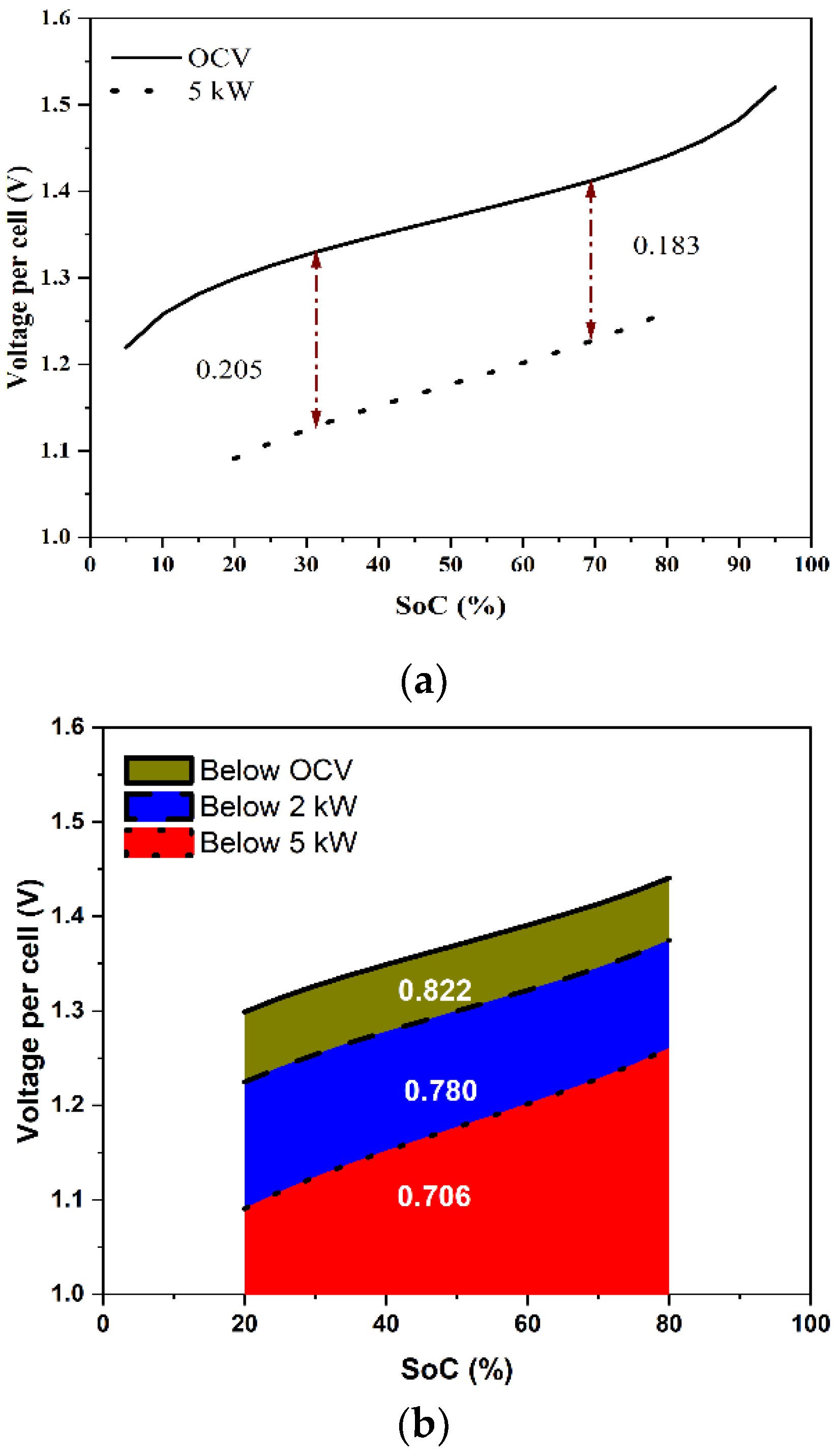
Figure 9.
Estimation of the stack power rating of the present stack during charging and discharging when using 10% energy loss in each process as the criterion for the power rating.
Figure 9.
Estimation of the stack power rating of the present stack during charging and discharging when using 10% energy loss in each process as the criterion for the power rating.
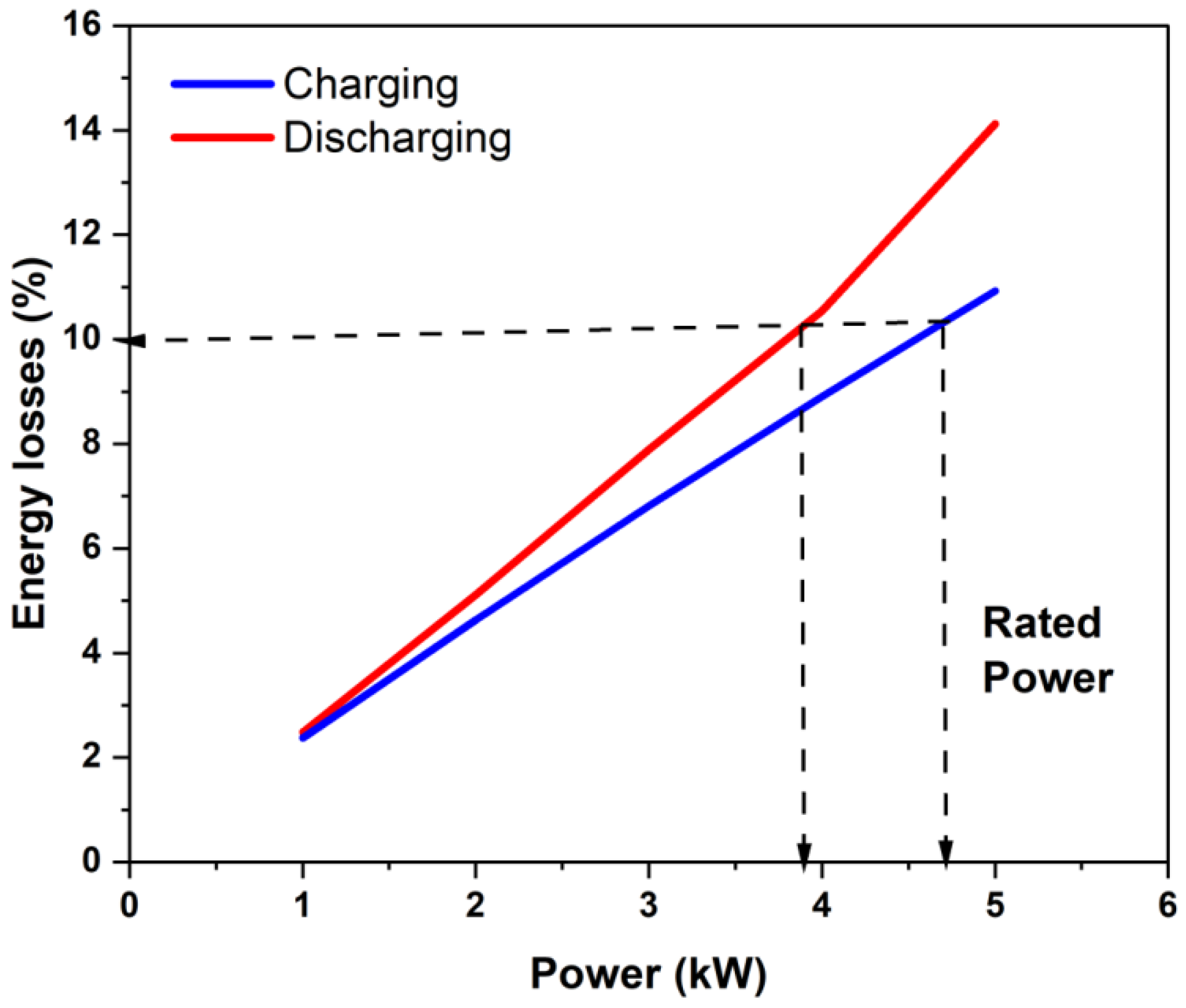
Figure 10.
Application of the proposed stack power rating concept to the stacks of (a) Zhao et al. [12] and (b(i),b(ii)) Guarnieri et al. [16]. (b(i)) shows the energy loss percentage as a function of operating power while (b(ii)) shows the power rating of the stack having loss characteristics shown in (b(i)).

Figure 11.
Estimated round-trip efficiency of the present stack for different power ratios and power levels if operated in an SoC range between 20% and 80%. The numbers in brackets indicate (charging power and discharging power), with both in kW.
Figure 11.
Estimated round-trip efficiency of the present stack for different power ratios and power levels if operated in an SoC range between 20% and 80%. The numbers in brackets indicate (charging power and discharging power), with both in kW.

Table 1.
Comparison of estimated energy storage cost of redox flow battery systems [9].
Table 1.
Comparison of estimated energy storage cost of redox flow battery systems [9].
| S No. | Redox Species | OCV (V) | Energy Cost (USD/kWh) |
|---|---|---|---|
| 1 | Fe-Cr | 1.2 | 250–450 |
| 2 | All-Vanadium | 1.2–1.6 | 175–400 |
| 3 | Zn-Br | 1.8 | 200–400 |
| 4 | Zn-Ce | 2.3 | 750 |
Publisher’s Note: MDPI stays neutral with regard to jurisdictional claims in published maps and institutional affiliations. |
© 2022 by the authors. Licensee MDPI, Basel, Switzerland. This article is an open access article distributed under the terms and conditions of the Creative Commons Attribution (CC BY) license (https://creativecommons.org/licenses/by/4.0/).
Share and Cite
MDPI and ACS Style
Vudisi, P.K.; Jayanti, S.; Chetty, R. Model for Rating a Vanadium Redox Flow Battery Stack through Constant Power Charge–Discharge Characterization. Batteries 2022, 8, 85. https://doi.org/10.3390/batteries8080085
AMA Style
Vudisi PK, Jayanti S, Chetty R. Model for Rating a Vanadium Redox Flow Battery Stack through Constant Power Charge–Discharge Characterization. Batteries. 2022; 8(8):85. https://doi.org/10.3390/batteries8080085
Chicago/Turabian StyleVudisi, Pavan Kumar, Sreenivas Jayanti, and Raghuram Chetty. 2022. "Model for Rating a Vanadium Redox Flow Battery Stack through Constant Power Charge–Discharge Characterization" Batteries 8, no. 8: 85. https://doi.org/10.3390/batteries8080085
Note that from the first issue of 2016, this journal uses article numbers instead of page numbers. See further details here.