1. Introduction
The need to provide clean and affordable energy contributing to a sustainable future is becoming of paramount importance. Vanadium redox flow batteries (VRFB) are the most promising electricity-storage system [
1,
2,
3] to address the intermittency issues of renewable energy sources, promoting smart-grid applications as well as self-consumption uses.
Despite some encouraging features such as energy and power decoupled values, fast response time, and easy scalability, the practical application of VRFB is limited due to the high capital investment cost [
4,
5]. The stack is one of the main components that contributes to the high capital cost together with the vanadium electrolyte, and more importantly, it defines the performance of the VRFB. In addition to the important role of the membrane and the electrolyte, the electrodes support the electrochemical reaction [
6], directly determining the efficiency and power/energy density values. It is well known that the commercial electrodes present some shortcomings due to the side reaction issues and sluggish kinetics for the positive half-cell reaction [
7], both of which induce voltage losses while in use. The impact of these issues leads to a dramatic decrease in the following key performance parameters:
- (1)
Low rate capability (charge/discharge at high current density)
- (2)
Short lifespan caused by low reversibility as well as poor round-trip efficiency
- (3)
Low electrolyte utilization ratio (EU%)
- (4)
Poor power peak values
- (5)
Low columbic efficiency due to the contribution of side reactions
Another important issue regarding the electrodes is the low amount of the active sites (i.e., O-containing groups), which affects the penetration of the electrolyte (hydrophilicity) and facilitates the oxygen transfer step, crucial step for the positive half-cell reaction [
8,
9]. Finally, improved mass transport is beneficial for the battery since it directly affects the rate of electrochemical conversion. Enhanced mass transport properties boost the refreshing of the products on the electrode surface (sites), allowing access to the larger volume of the fresh electrolyte. This can be attained with convective transport, leading to a higher contribution in pumping costs. In order to avoid high costs, outstanding mass transfer properties in the electrode are required [
10].
Consequently, the scientific community has been investigating the implementation of catalysts on the commercial electrodes. There are recent reports on several procedures with metal oxides [
11,
12,
13,
14], nitrogen and oxygen doped materials [
15,
16,
17], and hybrid materials [
18,
19,
20]. These treatments have been demonstrated to enhance the reaction kinetics in VRFB, overcoming the polarization issues. Unfortunately, despite tremendous efforts being invested in the development of new materials and functionalization surface treatments, their industrial application remains a major challenge. The critical limitations are the laborious and long-term synthesis process, implying, in some cases, high-cost materials with sophisticated equipment. Another important issue related to the positive electrode in VRFB is the lack of the long-term stability because the electrode suffers degradation due to a harshly acidic medium and high potential values occurring during the charging process. Thus, the preparation of the highly electrocatalytic graphite-based electrodes for a positive half-cell reaction is of critical importance in order to boost the VRFB technology.
2-D Graphene-based materials are attractive as energy storage material due to a high electrical conductivity, mechanical and chemical stability as well as a large surface area (i.e., single graphene sheet is 2630 m2·g−1). Therefore, the combination of porous materials (i.e., graphite felt, GF) with 2-D graphene is an effective strategy to achieve carbon-based materials with outstanding features such as high-ion accessible surface area and low-ion transport resistance, while maintaining the porous 3-D network of the commercial electrode. In particular, graphene derivatives that contain some oxygen functional groups such as graphene oxide (GO) can be used as a suitable material without compromising the high electrical conductivity while, at the same time, overcoming the aforementioned issues in a positive reaction.
In this framework, the first steps are reported for the production of a thin-layer graphene oxide (GO)–wrapped onto a graphite felt surface (GO-GF) electrode via electrospray. This easy-to-use technology offers the following benefits [
21]: (1) a straightforward and cost effective procedure, (2) non-toxic and low-cost materials (GO-water suspension); (3) a firm control of the deposition layer-by-layer process through experimental parameters (i.e., flow rate, electric field and dispersion), which strongly influence the Taylor cone formation,: (4) suitability for large-scale applications, allowing modification of up to 2000 cm
2 electrodes; (5) alignment of the freestanding GO single-flakes with the electric field. Herein, the optimization of the voltage has been done by applying low (9 kV) and high voltage (13 kV), thereby obtaining different morphologies and distributions, which strongly influence on the activity towards the positive reaction in VRFB (i.e., diffusion and reversibility). The evaluation of the electrochemical properties has been performed with fundamental electrochemical techniques, for example, cyclic voltammetry and electrochemical impedance spectroscopy.
2. Results
2.1. Characterization of As-Prepared Electrodes
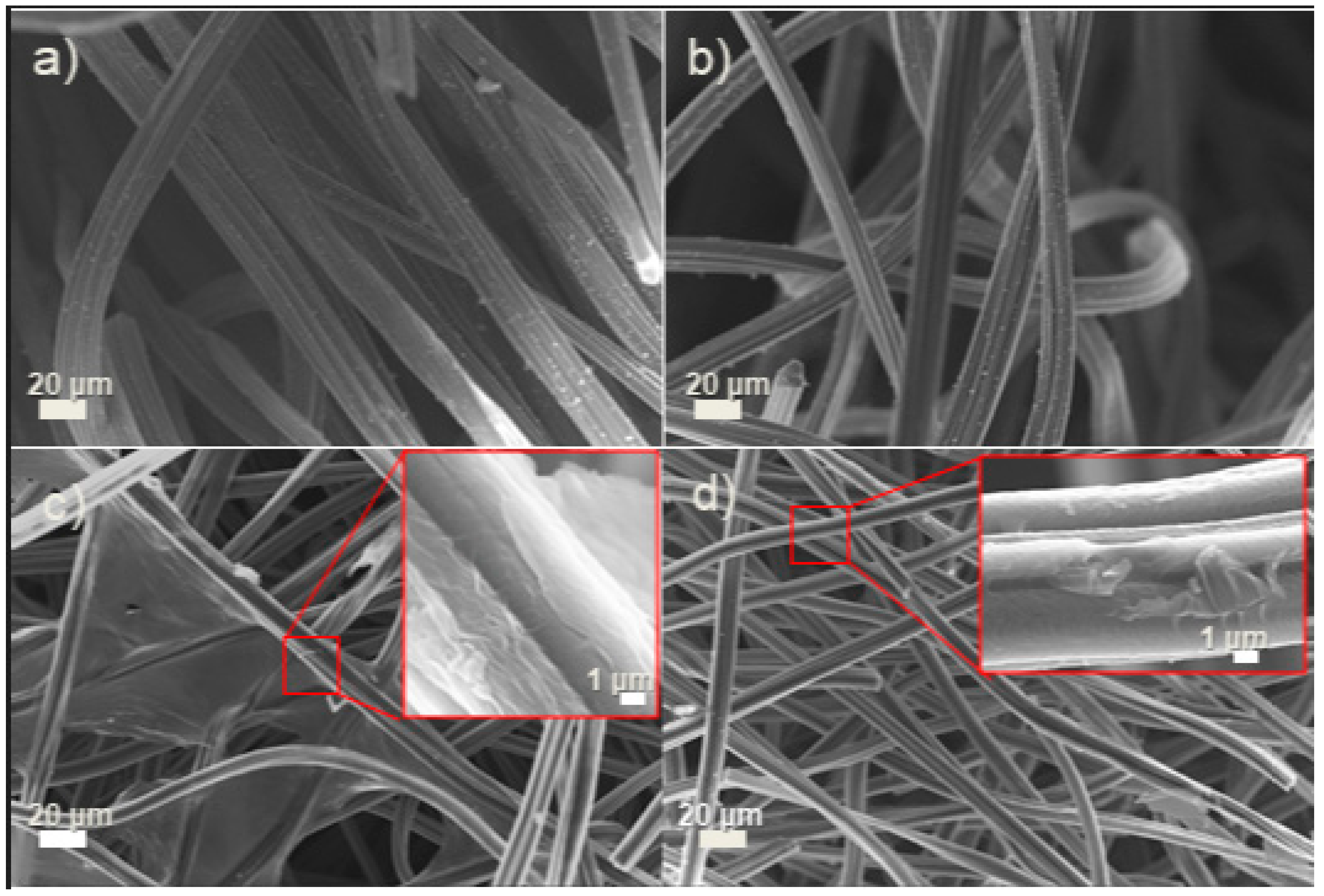
The morphological structure of the as-prepared electrodes was characterized by FE-SEM.
Figure 1a shows a thermally treated graphite-felt (TT-GF) electrode, which is composed of several thinner fibers stacked in a 15–10 µm diameter with a relatively smooth surface. The stacked fibers form a 3D well-interconnected network with porous architecture (
Figure 1a), which facilitates mass transport of the electrolyte. Compared with the plasma-treated (P-GF) electrode, negligible differences can be appreciated in the morphology of the GF electrode, indicating that no alterations have been produced by the plasma treatment (
Figure 1b). After electrospray-deposition, a thin layer of graphene oxide (GO) can be easily observed, covering the surface of the GF electrode. Hence, the GO thin layer exhibits different morphologies compared with the P-GF, depending on the voltage applied during the electrospray process. Mostly at a lower voltage (GO_L@GF electrode), the GO-sprayed sheets are aligned layer-by-layer on the same plane as the GF electrode, enabling the GO to cover the pores of GF (
Figure 1c). This fact may not be beneficial since the access to the electrolyte is limited and the diffusion of ions from/to the electrolyte inside the pores is blocked (inset of
Figure 1c) [
22]. On the contrary, when the high voltage was applied (GO_H@GF electrode), several thin-film GO layers appear homogenously distributed around the surface of the GF electrode, maintaining the same cross-linked network, as seen in
Figure 1d. It is important to note that the GF electrode is partially covered. This is beneficial because of the low electrical conductivity properties of the GO sheets. Higher magnification corroborates that the GO forms several nm-thin layers coating the GF-electrode fiber. In addition, the GO sheets appear to have a crumpled and porous morphology, which could increase the surface area of the GF electrode as well as provide more active sites for the reaction (inset of
Figure 1d).
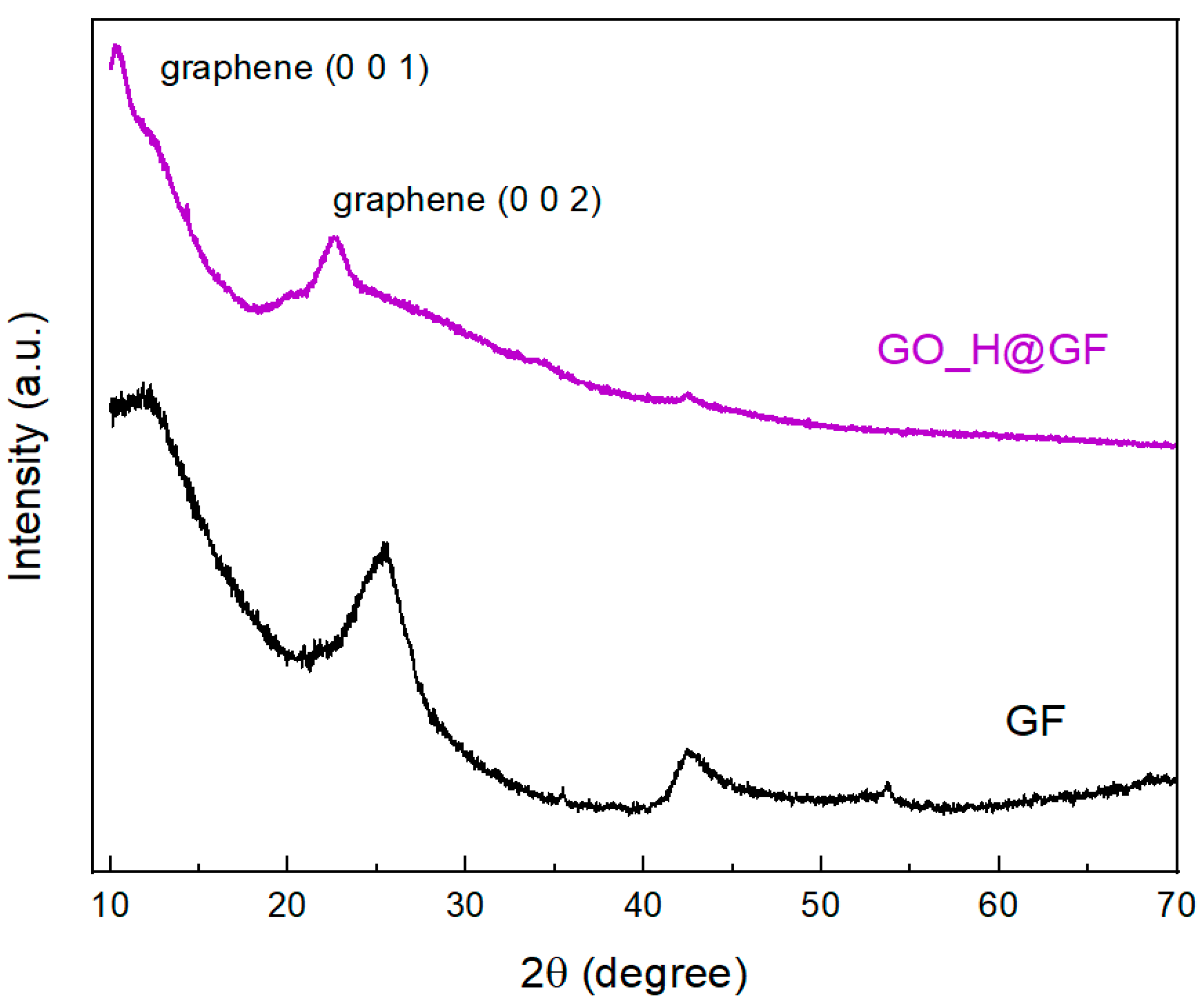
Crystal structures of the as-prepared electrodes were characterized by XRD.
Figure 2 shows the crystalline phase of GF electrode with the diffraction peaks at 2θ = 25.5° and 42.5°, consistent with the crystallographic (002) and (004) planes of the original GF electrode (graphite, JCPDS 075-1621), respectively. After the electrospray process, the GO_H@GF electrode shows XRD spectra with a (0 0 2) diffraction peak at 2θ = 22.5° corresponding to graphene [
23], with an estimated interlayer distance of around 0.4 nm. Additionally, an initial signal at 2θ = 11° suggests the presence of (001) planes of graphene, with a larger interlayer distance of 0.8 nm, due to the presence of the remaining oxygen groups. Finally, the diffraction peak at 2θ = 42.5° corresponding to (100) planes is also observed.
2.2. Application of As-Sprayed Electrodes for Positive Half-Cell Reactions in VRFB
Based on the characterization of the as-sprayed GF electrodes discussed above, remarkable performances towards the positive half-cell reaction can be envisaged. To further corroborate this hypothesis, cyclic voltammetry (CV) and electrochemical impedance spectroscopy (EIS) experiments were carried out for all as-prepared electrodes.
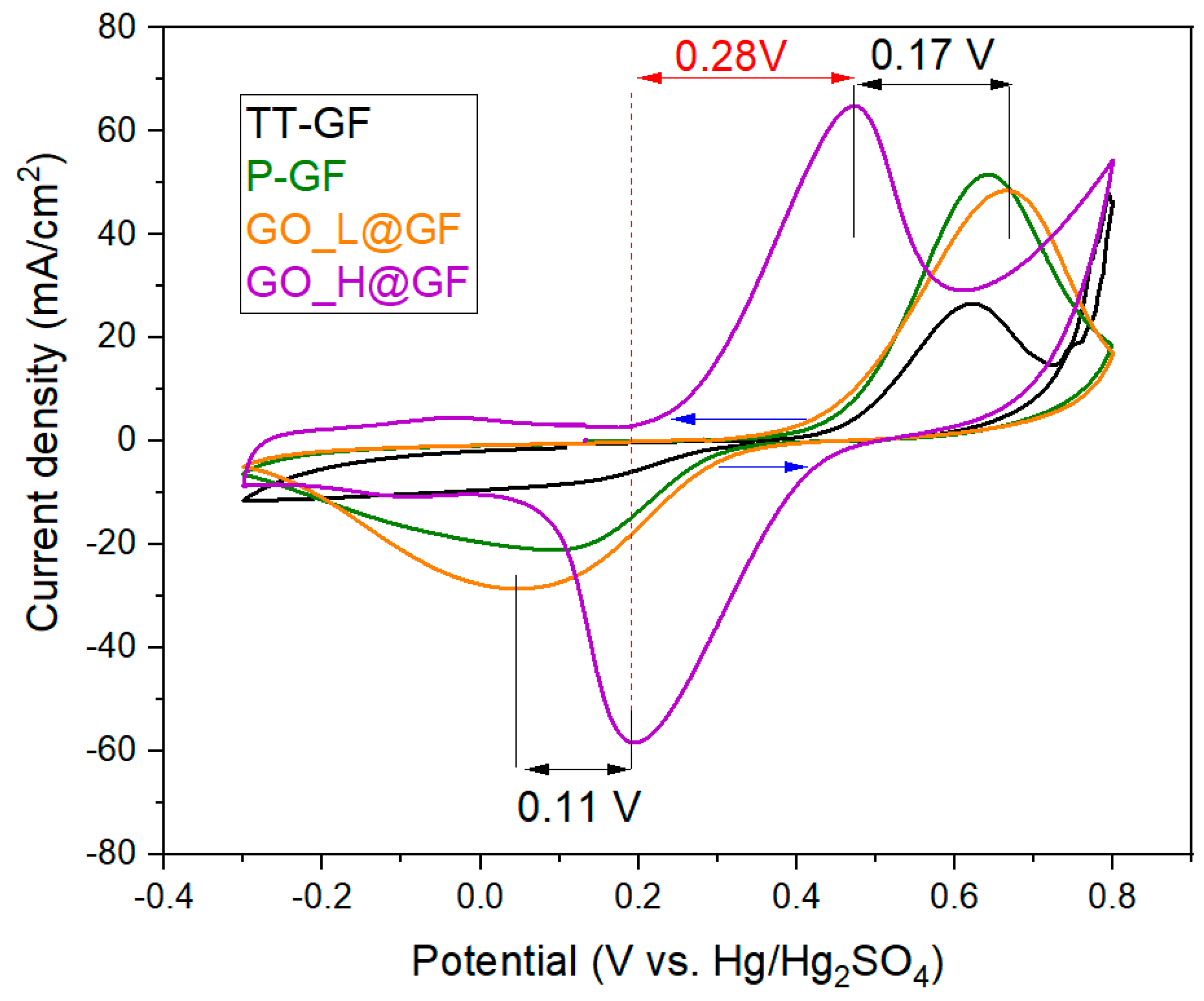
Figure 3 exhibits the 5th cycle of CV curves, where the main electrochemical parameters can be obtained (
Table 1).
The poor electrocatalytic activity of the TT-GF towards the positive half-cell reaction is clearly evidenced in VRFB from the almost indistinguishable reduction peak. These irreversibility features have been extensively reported in the literature. On the contrary, the CV profiles of the P-GF and GO-based electrodes display a classical reversible behavior towards the positive half-cell reaction with two well-defined peaks for both reduction and oxidation processes, attributed to the following reaction:
Additionally, negligible differences can be found between P-GF and GO_L@GF electrodes. It is notable that both the higher reduction current peak (~28 mA·cm−2) and the lower onset potential value for the anodic process (0.38 V vs. Hg/Hg2SO4) are displayed by the GO_L@GF electrode. This can be attributed to the incorporation of GO sheets. Interestingly, further differences can be observed by comparing GO_L@GF and GO_H@GF electrodes:
- (1)
The onset potential value for both the oxidation process (V
4+ to V
5+) and the reduction process (V
5+ to V
4+) is significantly reduced (see blue arrows in
Figure 3) with the GO_H@GF electrode compared with a GO_L@GF electrode. The same trends can be appreciated with the oxidation and reduction peak potentials (black arrows). For example, the E
pa and E
pc were reduced by 0.17 and 0.11 V, respectively, using a GO_H@GF electrode. This fact indicates that a more favorable process can be carried out with a GO_H@GF electrode in terms of electron-transfer kinetics and energy efficiency.
- (2)
The highest current densities for both processes (i.e., oxidation and reduction) are displayed by the GO_H@GF electrode (i.e., Ipa = 65.06 mA·cm−2 and Ipc = −58.5 mA·cm−2). The higher current densities collected are indicative of the fact that a higher conversion is produced since a larger amount of the vanadium species is adsorbed on the surface of the electrode and is oxidized/reduced on the active sites.
- (3)
The lowest peak-to-peak potential separation (ΔEp) was attained by the GO_H@GF electrode in comparison with all electrodes tested (0.28 V, red arrows). In addition, the ratio of the reduction peak to the oxidation peak current (Ipa/Ipc) is around 1.1, closer to unity than the value obtained with the GO_L@GF electrode. These parameters are indicative of the positive reaction being more reversible in the GO_H@GF electrode than in the GO_L@GF electrode.
- (4)
The equilibrium potential value determined for GO_H@GF electrode was found to be 1.0 V vs. NHE, the lowest value of all as-prepared electrodes, indicating that the reaction needs lower energy values when the GO_H@GF electrode is used.
The results indicate that the electrocatalytic kinetics of the redox process on the electrodes are in the order of GO_H@GF >>> GO_L@GF~P-GF > GF. Thus, the positive half-cell reaction can be performed more easily on the GO_H@GF electrode than on the TT-GF electrode.
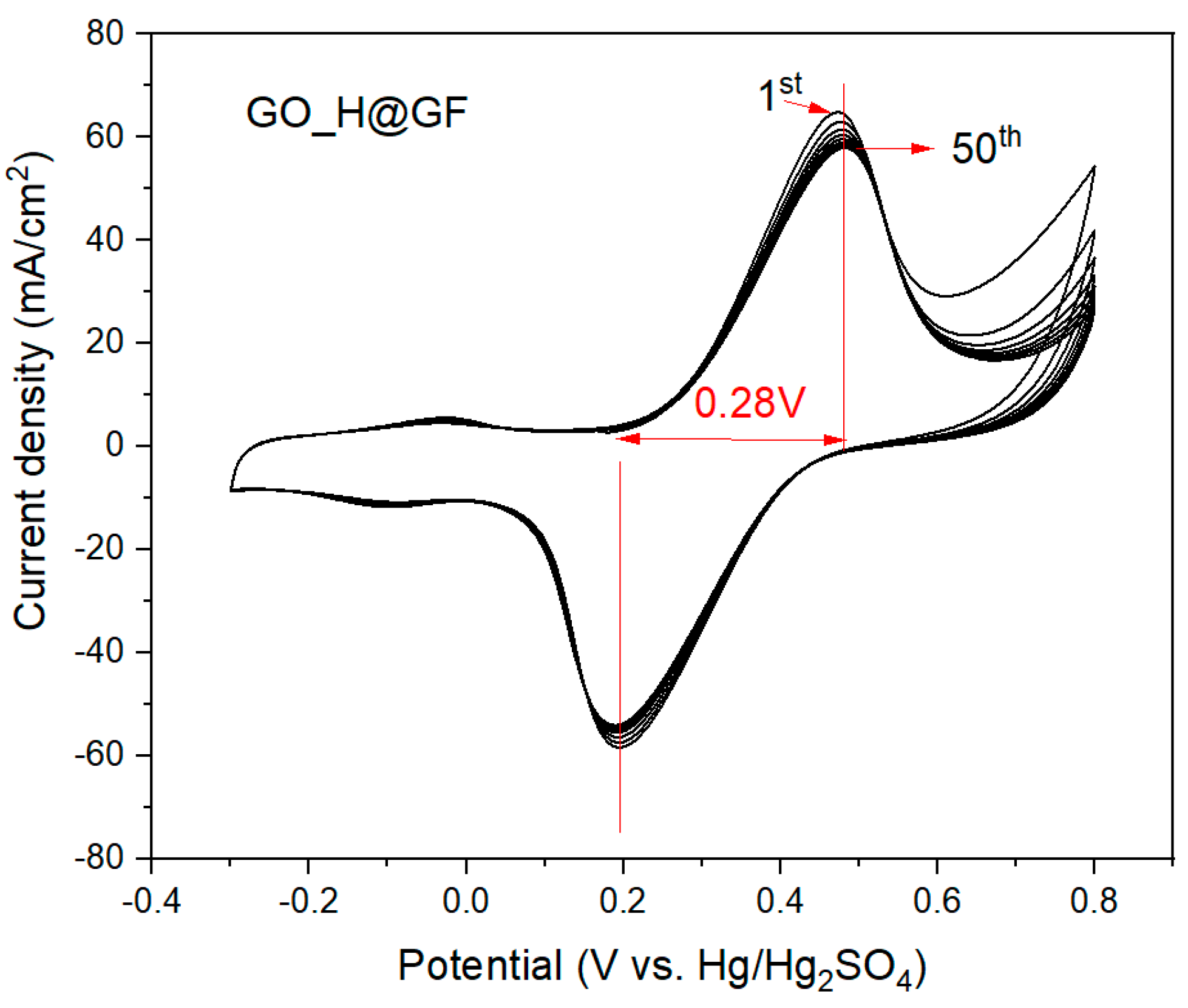
In order to assess the long-term stability of the GO_H@GF electrode, up to 50 repetitive cyclic voltammetries were performed as showed in
Figure 4. No significant change (less than 10% of variation in current density values) in electrocatalytic activity (i.e., peak current density and reversibility) can be appreciated after the measurement. Consequently, this functionalization treatment based on a cost-effective electro-spray process using GO suspensions supposes a step forward for a VRFB system due to the electrochemical performance and long-term stability.
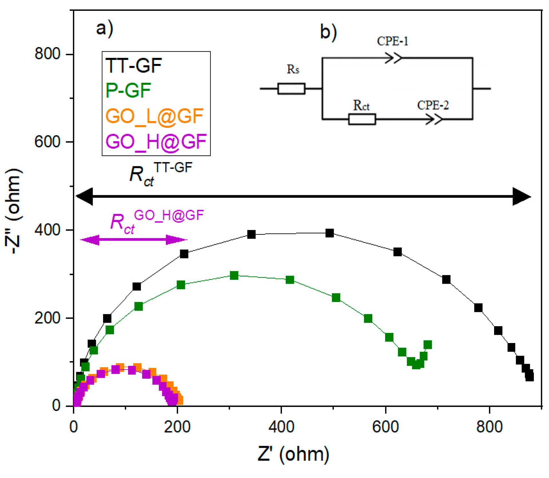
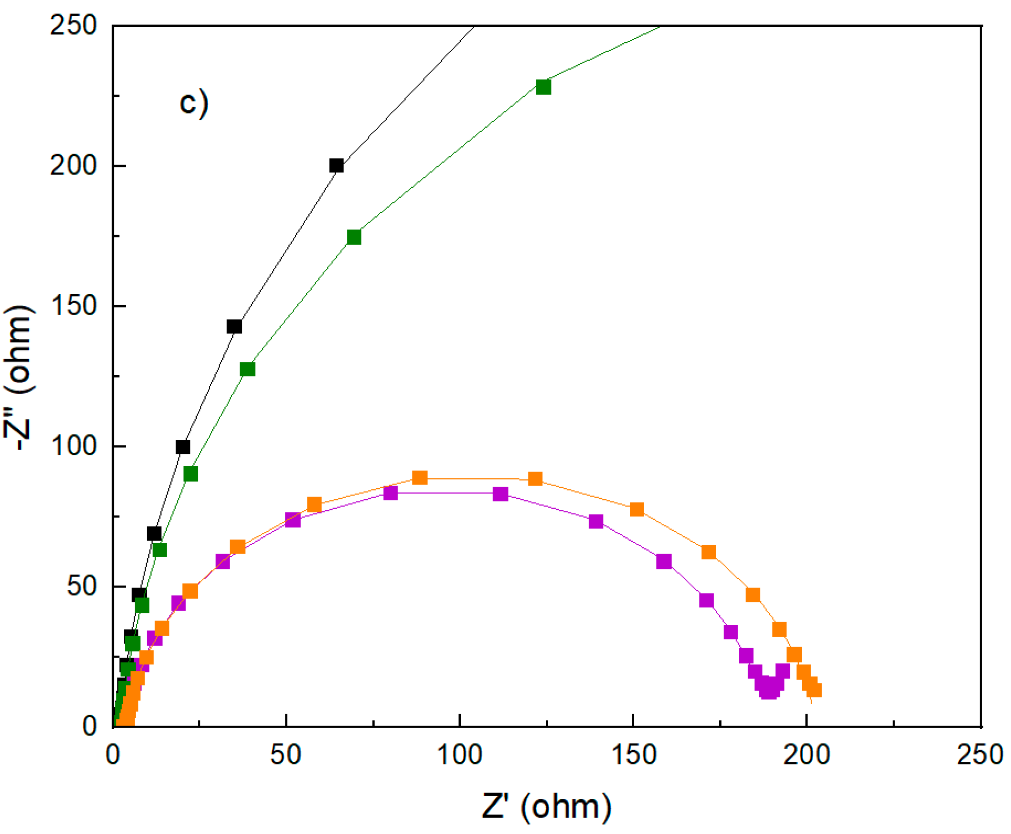
To investigate the kinetics through the charge transfer properties of the as-prepared electrode, EIS at OCV was carried out. The Nyquist’s plot (
Figure 5) of all as-prepared electrodes comprises different behaviors: (1) semi-circle indicating the charge transfer process at the interface of the electrode material and the electrolyte solution with the absence of the diffusion contribution; (2) two regions ascribed to charge transfer and diffusion processes, at the high and low frequency regions, respectively. The TT-GF and GO_L@GF electrodes resemble the first type, indicating that the reaction is purely controlled by charge-transfer. On the contrary, with the P-GF and GO_H@GF electrodes, the reaction exhibits a mixed control with charge transfer and diffusion. For the latter type, the data was fitted using a Randles equivalent circuit (
Figure 5b). The following elements can be attributed to: (1) the R
s element represents the electrolyte resistance, combining the electrode resistance and interface resistance; (2) CPE-1 is the constant-phase element, which is indicative of the double-layer capacitance (C
dl) of the interface between the electrode and the electrolyte, (3) the charge transfer resistance (R
ct), and (4) CPE-2 is the constant-phase element which represents the diffusion capacitance in the pores of the electrodes, attributed to VO
2+ and VO
2+ ions. The parameters obtained after fitting the data are listed in
Table 2 for less than 10% error.
These results show negligible differences in Rs values, with a minimum increment in the GO-based electrodes due to its low electrical conductivity. By contrast, Rct values show high dependency on the treatment performed on the GF electrode. For example, the Rct showed reduced values in the following order (in parenthesis the Rct values, ohm): GO_H@GO (183)~GO_L@GO (199) <<< P-GO(638) < TT-GF(857). The reduced Rct value of the GO_H@GF electrode suggests a faster charge transfer process as well as a higher rate towards the positive reaction. Comparing Y1 values, it can be found that the GO_H@GF electrode offers the best value, indicating that the highest double-layer capacitance values are obtained with the GO_H@GO electrode. This analysis is highly consistent with CV results, where the highest current density is collected from this electrode, which indicates that the charge transport is favored using the GO_H@GF electrode. Surprisingly, the absence of diffusion features in the pores of the TT-GF and GO_L@GF electrodes must be noted. By contrast, the diffusion capacitance (Y2) is increased using the P-GF and GO_H@GF electrodes, achieving the best value for the latter electrode.
3. Discussion
We have performed the first steps towards the synthesis of a positive electrode with high electrocatalytic activity for VRFB applications via a feasible, green and low cost rout. This novel electrode consists of a graphene oxide (GO) wrapped on graphite felt, synthesized via an electrospray using as precursor a GO-based water suspension. The electrospray process allows the production of easy-to-make and layer-by-layer GO coatings, leading to nanostructure scaffolds that can be tailored in accordance with the final application. It is important to note that the electrospray process allows an excellent contact between the GO and GF felt, leading to outstanding electrical conductivity properties.
Furthermore, the optimization of the parameters such as applied voltage is crucial to achieve a homogeneous distribution and a stable coat. The shape of the Taylor cone plays an important role in achieving this goal. For this reason, the voltage value has been optimized and the effect on the morphology has been investigated. When the low voltage values are applied, the dispersion cannot produce droplets, which essentially fall by gravity in random way. On the other hand, a stable jet mode is achieved at a high-applied voltage, producing a stretching along the capillary axis. This is the so-called Taylor cone, which enables an ordered scaffold. According to the FE-SEM images, for the GO_L@GF electrode produced at 9 kV, the applied voltage does not seem to be sufficiently high since non-homogenous deposits have been achieved. More importantly, the GO sheets have been aligned to the substrate, anchoring into the pores of the GF electrode. At high voltage (13 kV), a stable Taylor cone can be observed, producing a homogenous and partial coating of the GF electrode, where the GO is wrapped to the fibers (GO_H@GO electrode).
The faster kinetics of vanadium redox couples on the GO_H@GO electrode can be attributed to the large surface area and abundant O-groups as active sites [
23,
24], facilitating the charge transfer. Accordingly, it was inferred that a GO-wrapped into GF electrode is an advantage to adsorption and desorption of vanadium ions (i.e., enhanced reversibility), leading to a decrease in the cell over-potentials.
Comparing with our previous article using WO
3 and N-containing groups over carbon felt [
13], the notable improvement in the enhancement of electrocatalytic parameters can be easily appreciated, see
Table 3:
Even though it is not the objective of this work, it is relevant to point out that the thickness of the GO coating as well as the effect of the electrospray process on the reduction of GO are an important parameters that can be considered in the future. Additionally, the increment in the electrical conductivity by partially reduction treatment of the GO (rGO) could be an excellent strategy for enhancing the electrochemical activity (i.e., improved charge transfer value). The optimization of the electrical properties and O-containing groups through the rGO/GO ratio in the graphene-based electrocatalyst is required for the knowledge of the mechanism. Finally, the evaluation of the performance in a flow-cell using the aforementioned GO-based GF electrodes will be performed in order to guarantee the practical application.
4. Materials and Methods
Fabrication process: Graphite felt (GF) was kindly provided by SGL group (SIGRACELL, GF 1.5 mm-thickness). In order to remove the impurities, the GF electrode was air-treated at 400 °C for 30 h. This sample was labeled thermally-treated GF (TT-GF) electrode. After that, oxygen-plasma for 10 min in each side was applied to TT-GF electrode in order to improve the hydrophilicity and wettability. This electrode was denoted by P-GF. Finally, the graphene oxide (GO) thin-film layer was deposited in 25 cm
2-P-GF electrode via electrospray techniques. For this purpose, electrospray was performed using diluted solution of GO (20 mg·L
−1) in deionized water (500 mg·L
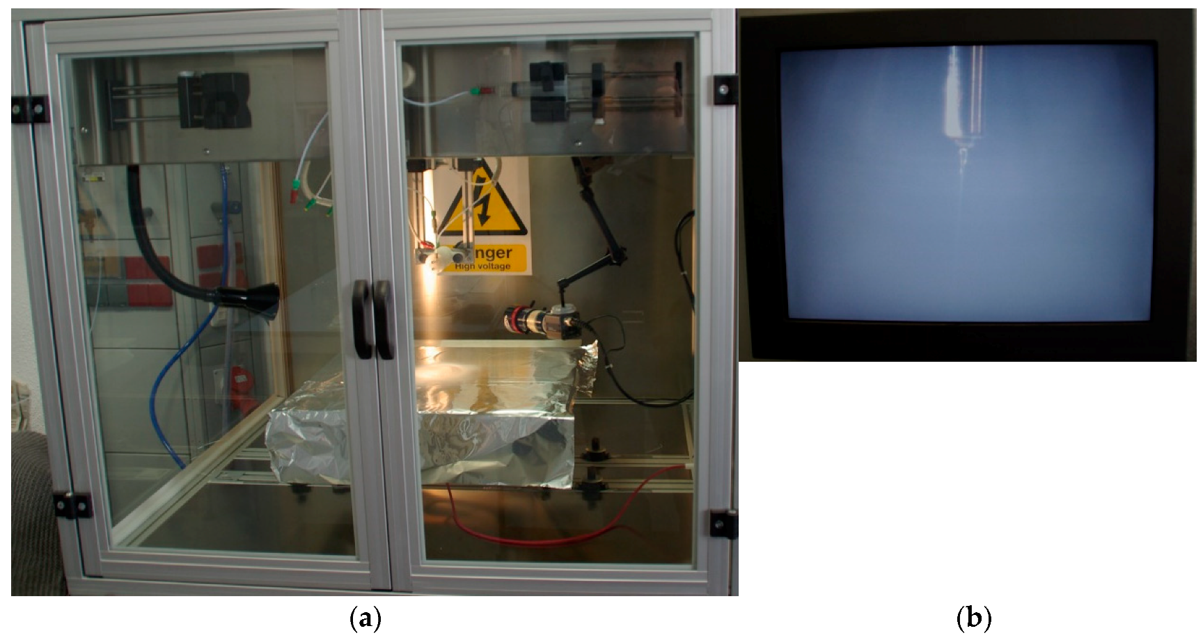
−1 Graphene Supermarket, USA). This solution was stirred until complete suspension before spraying. The electrospray process was carried out under ambient condition using YFlow Electrospinner 3.2.D-400, working as electrospray mode (
Figure 6a). The as-prepared solution was supplied thorough the stainless steel needle (Ø
int: 0.6 mm; Ø
ext: 0.9 mm), applying a flow rate of 1.9 mL·h
−1 with a syringe pump. A grounded roller was used as a product collector, where the P-GF electrode was placed in order to be wrapped by the GO (
Figure 6b). Two different voltage values were evaluated with a continuous control of the Taylor cone by means of a camera (
Figure 6b) (i.e., low voltage 9 kV or high voltage 13 kV). The Voltage applied to needle (V−), voltage applied to current collector (V+), needle-to-collector distance (d) and collection time (t) are shown in the
Table 4 for each GO-sprayed on GF electrode. The samples obtained applying low voltage and high voltage were labelled as GO_L@GF and GO_H@GF electrodes, respectively. After that, the as-spray electrodes were dried in the oven overnight. Finally, to obtain active GO-based GF electrodes, the as-electrodes were air-treated at 300 °C for 12 h.
Structural characterization: The morphology of the as prepared electrodes was observed by using a Zeiss Auriga field emission scanning electron microscope (FESEM) microscope. The crystalline structure was analyzed via X-ray diffraction (XRD), using A Bruker D8 Advance diffractometer equipped with a Cu Kα (1.54051 Å) radiation.
The crystalline structure was analyzed via X-ray diffraction (XRD), using A Bruker D8 Advance diffractometer equipped with a Cu Kα (1.54051 Å) radiation.
Electrochemical performance towards positive half-cell reaction: The electrochemical properties were evaluated by means of cyclic voltammetry (CV) and electrochemical impedance spectroscopy (EIS) in a conventional three-electrode cell. For this purpose, all as-prepared electrodes (diameter 6 mm), large Pt mesh and Hg/Hg
2SO
4/Sat. K
2SO
4 (0.664 V vs. SHE) electrode were used as working electrode, counter and reference electrode, respectively. A 0.05 M VOSO
4 in 1 M H
2SO
4 solution was used as electrolyte (20 mL), which was previously deaerated. In order to compare all as-prepared electrodes in terms of electrocatalytic activity, CV was performed at 10 mV/s. Several fundamental parameters were extracted from the CV analysis as key parameters of the electrocatalytic activity, detailed as follow: (i) Current density values for oxidation and reduction peaks (I
pa, I
pc); (ii) Onset potential and peak potentials (E
pa, E
pc); (iii) The ratio of oxidation and reduction peak current densities (I
pa/I
pc, close to 1 for reversible one electron process); (iv) and peak-to-peak potential separation (ΔE
p = 59 mV for reversible one electron process; and (v) Equilibrium potentials (E
0) determined from the following equation:
After that, repeated CVs at 10 mV/s were performed in order to evaluate the long-term stability. Finally, the electron transfer properties as well as diffusion features were studied by electrochemical impedance spectroscopy (EIS), applying alternating voltage of 10 mV over a frequency range of 100 kHz to 10 mHz at zero volts vs. open circuit potential.
5. Conclusions
In summary, we successfully perform the first steps for the synthesis of a positive electrode for vanadium redox flow battery applications with a highly electrochemical activity by means of a straightforward, environmentally friendly and cost-effective rout. This novel electrode consists of a graphene oxide (GO) wrapped on graphite felt, synthesized via an electro-spray with GO in water suspension as precursor. The process is optimized in terms of applied voltage, allowing high voltage to achieve a homogenous distribution. This optimized condition enables the GO to wrap itself around the fibers of the GF electrode. This different morphology strongly affects the electrocatalytic properties. By comparing all electrodes, GF_H@GF shows the best electrocatalytic activity towards the positive reaction, allowing to attain: (1) Reduced peak potentials in 0.17 and 0.11 mV for anodic and cathodic processes, respectively; (2) Lower values for onset potential for the anodic process; (3) 2.4-folds higher current density values for anodic peak and a remarkable cathodic peak increase of up to 58 mA·cm−2 in comparison with the TT-GF electrode; (4) Higher reversibility (0.28 V at 10 mV·s−1); (5) Long-term stability. EIS analysis has corroborated these features, showing a decreased electron charge transfer resistance in ca. 4 times versus the TTGF electrode. It is important to note the improved diffusion capacitance, facilitating the diffusion of the vanadium ions. This novel electrode is presented as a promising strategy to overcome the performance limitations related to the positive reaction in VRFB.

 ,
, 


