Synthesis of Hybrid Silica-Carbon Tubular Structures by Chemical Vapor Deposition with Methane or Ethene


Grupo de Investigación Ciencia de los Materiales, Instituto de Química, Facultad de Ciencias Exactas y Naturales, Universidad de Antioquia, Calle 70 No. 52-21, Medellín 050010, Colombia
*
Author to whom correspondence should be addressed.
C 2018, 4(1), 1; https://doi.org/10.3390/c4010001
Submission received: 22 November 2017
/
Revised: 15 December 2017
/
Accepted: 18 December 2017
/
Published: 25 December 2017
(This article belongs to the Special Issue Carbon Nanotube and Applications)
Abstract
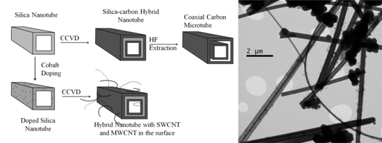
:Silica microtube and carbon nanotube hybrid structures have been synthesized by catalytic chemical vapor deposition using either methane or ethene as the carbon source, and cobalt-grafted or impregnated silica tubes (200–800 nm) as catalyst. The cobalt-grafted catalyst shows a high resistance to reduction (>1000 °C) and selectivity to single-wall carbon nanotubes (SWCNT). While ethene deposition produces more carbonaceous material, methane experiments show higher selectivity for SWCNT. After removing the silica with an excess of HF, the carbon nanostructure endured, resulting in a coaxial carbon nanostructure. The novel hybrid nanostructures obtained consist of a submicron-sized tube, with walls that are formed by a succession of carbon/silica/carbon layers to which multiwall (20–25 nm) and/or single-wall (0.6–2.0 nm) carbon nanotubes are attached. This synthesis approach combines the mechanical properties of carbon nanotubes and the thermal properties of silica tubes into a synergetic nanostructured material, opening further possibilities for polymer reinforcement and potential applications in catalysis.
1. Introduction
There is ongoing interest, globally, in research topics related to the development of new nanomaterials with unknown properties. Carbon nanostructures have gained widespread attention over the last 20 years because of their outstanding mechanical [1,2] and electrical properties [3,4], which have provided access to tube-like nanostructures. Carbon nanotubes have mainly been synthesized by three methods: laser ablation [5], catalytic chemical vapor deposition (CCVD), and arc discharge [6,7]. Each technique has been proved to have advantages and disadvantages, especially when control over the the structure is required.
The CCVD process has been shown to be one of the most promising methods, due to its high selectivity [8], high conversion rate, low-cost equipment, and the fact that the synthesis variables (i.e., temperature, pressure, mass flow, and carbon source) can be controlled. The use of a catalyst improves the selectivity [9], since the nanotubes’ diameter and structure are related to the metal´s particle size. The most common catalysts use cobalt, nickel, and iron particles that have been supported in mesoporous silicas (as MCM-41 and SBA-16) by grafting, in-situ incorporation, or impregnation methods [8,10,11,12].
Through the grafting method, a chemical bond between the support and metal clusters is induced via silanol exchange, which ensures the high stability of the catalyst. Through the in-situ incorporation, metal ions are mixed with the growing silica, incorporating the metal into the silica structure. It is to be expected that some chemical bonds are bound to occur, but with low thermal stability and a high degree of sintering. Finally, while the impregnation process is the fastest and cheapest among them [13], the stability and selectivity of the catalyst is very low, as no chemical bond is induced, which results mainly in multiwalled carbon nanotubes (MWCNT).
Silica microtubes and nanotubes (STs) have a high thermal stability, high aspect ratio, and a reactive surface consisting of silanol groups (Si–OH), which could be used to react with further functional groups through silane chemistry; therefore, they could be useful for multiple applications [14,15,16,17,18,19,20,21]. The silica tubes have mainly been synthesized by a sol-gel process using template methods, whereas in-situ formation of needle-like salts [14,22,23,24,25,26,27], or porous alumina membranes [15,20,28,29], are used as templates. Despite the fact that some authors have used carbon nanotubes as templates for the growth of the silica structure [30,31], the cost of this template is significantly higher than the others. One of the cheapest and simplest processes for obtaining the silica tubes is the one proposed by Nakamura and Matsui [23], in which in-situ formed DL-ammonium tartrate needle-like structures are used as templates [26]. Through this process, silica submicron tubes (0.8–1.0 µm) can be easily obtained alongside spherical silica particles as a byproduct.
In this study, we investigate the formation of silica-carbon hybrid nanotubes using cobalt-doped silica tubes (200–800 nm) as the catalyst, on which carbon nanotubes are grown by means of CCVD with methane or ethene. These tubular silica-carbon structures lead to the formation of a synergistic material [32] in a nanostructure likely to have good thermal, electrical, and mechanical properties.
2. Results and Discussion
2.1. Silica Tubes
The synthesis method proposed by Nakamura and Matsui was reproduced as the reference for this study. In order to obtain mainly silica tubular structures, avoiding the formation of spheres, the concentrations of water, DL-tartaric acid, and ethanol were systematically altered. These changes are related to the hydrolysis and condensation rates of Tetraethoxysilane (TEOS), as well as the amount of available templates for silica tube formation. Experimental molar ratios of water/TEOS/tartaric acid/ethanol for the experiments are shown in Table 1. Regarding silica, it is generally known that when the water/TEOS molar ratio (rw/TEOS) is <1, linear oligomers and fiber growth are the preferred form; while when rw/TEOS > 1, three-dimensional growth and formation of spherical structures is more likely [33].
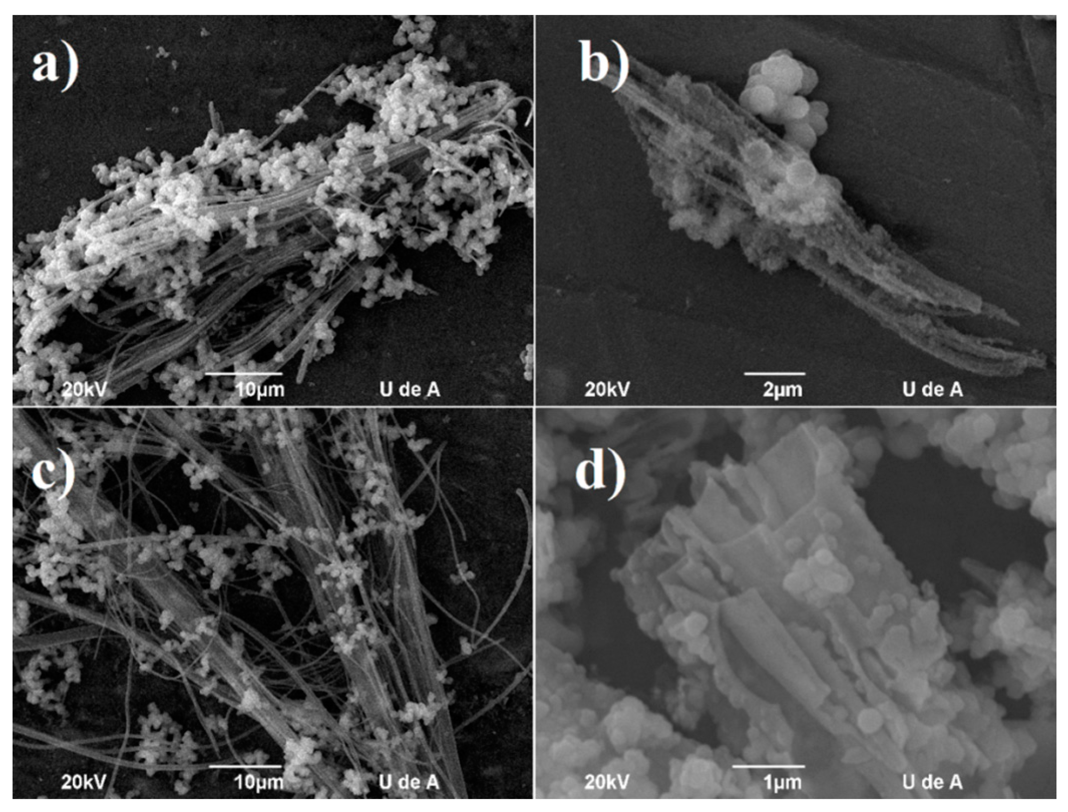
From Figure 1a, the sample obtained by the reference process (ST_ref with rw/TEOS = 1), the formation of tubes with diameters in the range of 200–800 nm is achieved along with high quantities of spheres or aggregates with diameters in the range of 1200 ± 500 nm. The sample with rw/TEOS = 2 (STw+) shows a low quantity of linear structures with heterogeneous colloidal spheres on the surface (see Figure 1b). This is attributed to the higher water concentration, which results in a higher degree of hydrolysis of TEOS oligomers and a higher solubility of the tartrate crystals. When the water content is lower (rw/TEOS = 0.5; STw-), smaller structures are obtained, probably due to the longer time required for the formation of the oligomers, and the more controlled deposition over the surface of the ammonium tartrate crystals. Miyaji et al. proposed that the crystals of DL-ammonium tartrate are responsible for the tube’s growth [26,27], so the solubility of the tartrate in the water/ethanol/ammonia mixture is critical. Hence, tartaric acid and ethanol content were changed as to ensure template availability. It was found that when ethanol content was lower (STe-), the solubility of the template was higher. Thus, lower template availability leads to fewer tubular structures.
When ethanol content was higher (STe+), the solubility of the template and the tartaric acid were lower. Consequently, to ensure dissolution of acid crystals and homogeneity in the vessel, pulverized material was used. This way, a higher content of tubular structures with fewer spherical particles were found (see Figure 1c). The use of a higher content of tartaric acid (STta+) caused rapid formation of larger crystals, and the formation of tubes was not achieved. Conversely, layered or broken structures were found (see Figure 1d).
Another factor found to be critical was the agitation that ensured the homogeneity of the system. In the reference synthesis, no agitation was employed, or it was not mentioned. It was found that when magnetic stirring was employed throughout the entire synthesis, no tube formation was observed. In contrast, when orbital agitation was performed for 10 s during the steps of the initial solution mixture (W+E+TA+TEOS, W = water, TA = Tartaric acid, E = Ethanol), as well as after the addition of the ammonia, the formation of tubular structures was enhanced. The sample STe+ with orbital agitation was used as starting material for further experiments in the catalyst preparation.
2.2. Cobalt-Silica Tube Catalysts
The impregnation process (ST-Im) leads to lightly magenta-colored samples before calcination, due to the deposition of cobalt nitrate on the surface of the silica. After calcination, samples became lightly brown, owing to the presence of cobalt oxides. Temperature programmed reduction (TPR) measurements showed a reduction peak at around 318 °C (see Figure 2a), which indicates low thermal stability of the cobalt on the surface of the silica, which produced sintering at relative low temperatures, and as a result, low selectivity for single-walled carbon nanotubes (SWCNT), as shown below. Thermogravimetric analysis (TGA) of impregnated catalyst showed that after coming into contact with the cobalt nitrate, no significant loss of silanol groups could be detected (see Figure 2b). In consequence, the low thermal stability can be explained by the absence of chemical bonds between silica and cobalt through the silanol groups [34]. Upon comparing it to untreated silica tubes (ST-B), a loss of weight is shown between 150 and 250 °C, which was attributed to coordination water molecules in the cobalt oxide.
The grafting process leads to a white product (ST-G), which turned light orange after calcination (ST-GC), and was indicative of the presence of cobalt oxides in the sample. By Atomic Absorption Spectroscopy, it was found that, regardless of the initial concentration employed, only 0.2 wt % of cobalt remained in the silica (measurements not shown). TPR measurements showed no reduction peak < 1000 °C (see Figure 2a), and TGA showed a significant loss of hydroxyl groups in the sample, compared to untreated silica (see Figure 2b), which suggests the formation of a chemical bond between the silica and the cobalt species due to its high thermal stability against the reduction of the grafted catalyst.
2.3. Hybrid Nanotubes
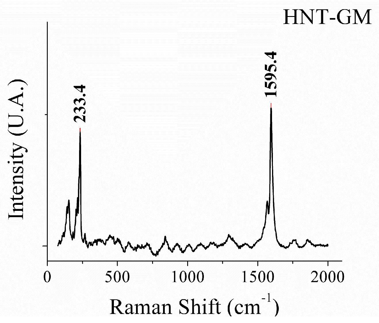
The TGA of the experiments using methane as a carbon source (see Figure 3) shows that carbon deposition was apparently not achieved in the silica tubes without cobalt (HNT-BM). In the case of the grafted sample (HNT-GM), only about a 0.6 wt % loss of weight can be seen in the range of 600–750 °C corresponding to graphitic material, which can be attributed to carbon nanotubes with low degrees of defects. This has been corroborated by Raman analysis (see Figure 4). The thermogram of impregnated tubes (HNT-ImM) shows a loss of weight of about 3.1 wt % in the range of 330–540 °C, which is characteristic of carbon decomposition that could be attributed to carbon nanotubes and amorphous carbon. This low carbon deposition could be attributed to the low reactivity of the methane under the conditions studied [35,36], especially the use of non-porous silica tubes as a catalyst support.
Raman spectra of the above samples show that no signal was found for the blank (HNT-BM), so absence of graphitic carbon was confirmed. Further, some noisily sharp bands appeared for the impregnated sample (not shown), which implies very disordered or amorphous structures. In the case of the grafted tubes (see Figure 4), sharp bands appeared at Raman shifts of 1592 and 233 cm−1, which are characteristic features of ordered graphitic layers (G-band), and Radial Breathing Mode (RBM) of SWCNTs, respectively. The absence of a band in the range of 1200–1400 cm−1 (D-band) indicates the presence of highly ordered structures. Perhaps, in light of the low yield reached, these results confirm the high selectivity of the system of cobalt-grafted silica tubes toward SWCNTs.
More interesting characteristics were found in experiments by CCVD with ethene, where carbon deposition was observed using the silica tubes without catalyst (HNT-BE25) in a mixed flux of C2H4:N2 (50:150 sccm, 25% C2H4). Thermogravimetric analysis carried out in air showed a loss of weight of about 7.7 wt % the temperature range of 550–670 °C, corresponding to graphitic carbon. After silica removal with HF (HNT-BE25P), the weight loss was about 78 wt % in the range of 400–600 °C (see Figure 5a). As can be seen, the decomposition temperature of the carbon material decreased by about 150 °C after removal of the silica. This thermal stabilization was attributed to the silica tubes’ protective effect. The final residues (22 wt %) may come from silica that was not dissolved by the HF, presumably because the carbon material protects the silica from dissolution. The scanning electron micrograph of the hybrid tubes HNT-BE25 shows that no carbon nanotubes (structures < 100 nm) were formed (see Figure 5b); instead, carbon layers deposited on the silica surface were found. This outcome was confirmed by Raman and Energy Dispersive X-Ray spectroscopy measurements (not shown).
Ethene deposition using impregnated tubes as catalyst (HNT-ImE25) showed a loss of weight of 14 wt % in the range of 490–660 °C (see Figure 5a). This result is comparable with those found in the literature [9], even when the silica tube support was non-porous. A yield improvement of around 6.3 wt % was achieved by using impregnated catalyst compared with the blank, which was attributed to the formation of carbon nanotubes and some amorphous carbon. The lower decomposition temperatures compared with blank might be due to catalyzed oxidation of carbon layers caused by cobalt particles remaining in the sample. By Raman spectroscopy, two characteristic bands at 1321 cm−1 (D-band) and at 1586 cm−1 (G-band) are found, within a G/D ratio of about 0.5 indicative of disordered carbon structures (not shown).
The formation of MWCNTs with diameters of between 20 and 40 nm attached to the surface of a submicron silica-carbon tube was confirmed by scanning electron microscopy (SEM) and transmission electron microscopy (TEM) analysis (see Figure 6), in which the higher magnification showed the catalyst particles inside the MWCNT, and the structural defects of the CNT. The SEM micrograph of the ethene deposition using the grafted catalyst (HNT-GE25) only showed the presence of small quantities of linear structures attached to the surface of a bigger structure. However, TEM analysis showed the presence of SWCNT and MWCNT, as well as the hollow hybrid structures found after silica removal (see Figure 7). At higher magnifications, a hybrid structure consisting of succession of carbon layer/silica layer/carbon layer/carbon nanotube became evident (see Figure 7b). After silica removal with HF, the carbon structure formed by two concentrically carbon submicron tubes, on which SWCNT and MWCNT were attached, was conserved (see Figure 7c).
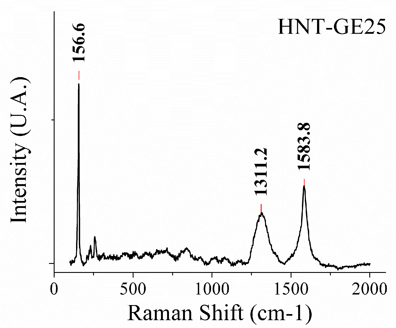
Raman spectra of the hybrid tubes HNT-GE25 showed characteristic bands at 1584 cm−1 (G-band), 1311 cm−1 (D-band), and one sharp band at 156 cm−1 (RBM of SWCNT) (see Figure 8). This result confirms the selectivity of the process for SWCNTs, even though the G/D ratio (the intensity ratio between the G and D bands) was about 0.5, which implied the formation of several amorphous carbon structures.
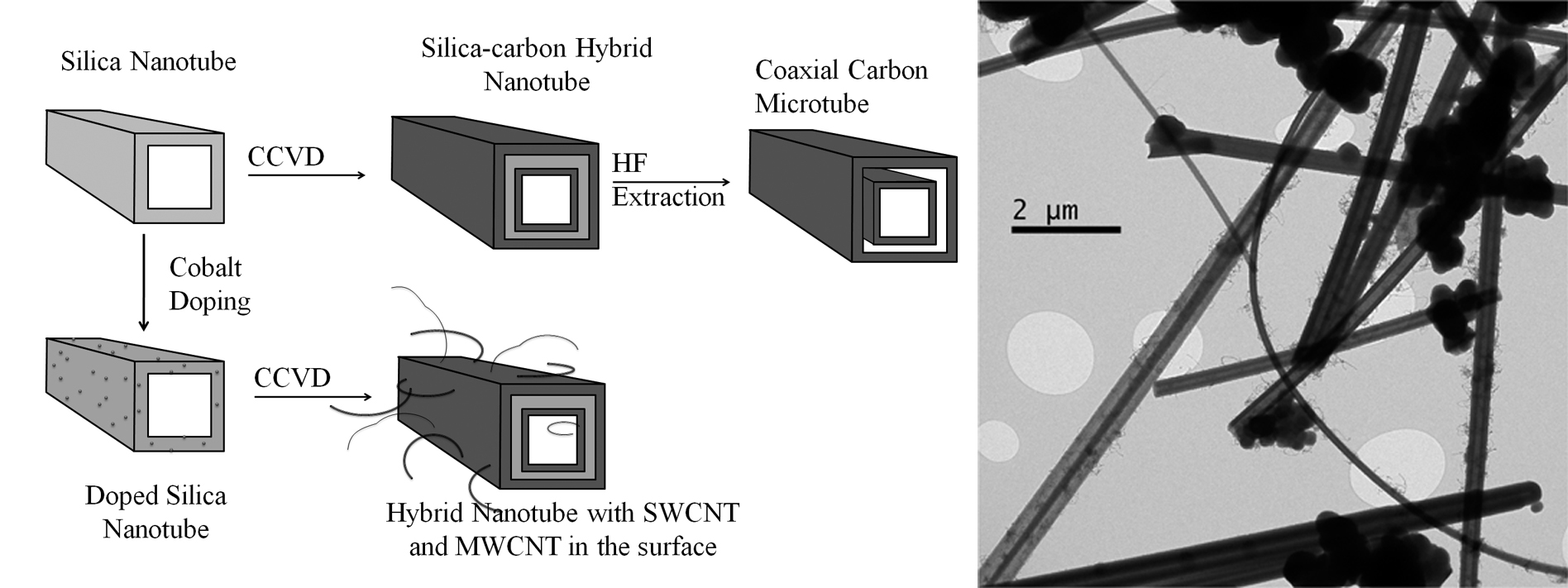
To study the effect of the C2H4:N2 flow ratio on the thermal behavior of the hybrid tubes, different mixtures were used in the CVD process. The TGA of samples prepared with 50:150 sccm (HNT-GE25), 10:90 sccm (HNT-GE10), and 20:80 sccm (HNT-GE20) is shown in Figure 7d. By comparing the samples obtained at the same flow (100 sccm), it can be inferred that, at higher ethene concentration, carbon deposition was enhanced by about 2 wt %, resulting in a more homogeneous material being obtained. This could be seen as a sharper signal in the Differential Thermogravimetric analysis (DTG) (shown in blue). Nonetheless, a small decrease in carbon content was found when the flow was raised and the ethene content was increased. This could be attributed to the higher contact time of the ethene with the catalyst at low flows, and the saturation of the reactive surface at high ethene concentration. In Figure 9, the process and the hybrid silica-carbon structures obtained in this study are presented, and are in accordance with the results shown above.
3. Materials and Methods
3.1. Materials
Tetraethoxysilane (TEOS, 98%), DL-Tartaric acid (99%), Ammonium hydroxide (28–30%), cobalt (II) acethylacetonate (97%) were purchased from Sigma-Aldrich (St. Louis, MO, USA); absolute ethanol from Mallinckrodt (St. Louis, MO, USA); cobalt nitrate hexahydrate (99%) from MP Biomedicals (Solon, OH, USA) and toluene from Honeywell Inc. (Morris Plains, NJ, USA). All materials were used as received without further purification.
3.2. Silica Tubes
Synthesis of the silica tubular structures was carried out by reproducing the method reported by Nakamura and Matsui with modifications [23]. Initially a mixture of DL-Tartaric acid (0.2 g), type I water (0.6 g), TEOS (7.3 g) and absolute ethanol (50 mL) is allowed to stand for 30 min, then ammonium hydroxide (20 mL) is quickly added and the mixture is left to stand for additional 20 minutes. Water, ethanol and tartaric acid content were changed to investigate the selectivity toward tubular structures.
3.3. Catalyst Preparation
Cobalt deposition on the silica surface was carried out by impregnation and grafting methods. For grafted samples (ST-G), silica tubes (1.0 g) and cobalt (II) acethylacetonate (5, 10, 15 and 30 wt % of Co.) were dried separately in toluene (115 °C, 100 mL) for 24 h under nitrogen atmosphere and continuous stirring, then the mixtures were allowed to react together in toluene reflux for another 24 h. Products were filtered and washed with toluene to remove unreacted cobalt. For impregnated samples (ST-Im), silica tubes (1.0 g) were dispersed in absolute ethanol for 30 min. Then, cobalt nitrate hexahydrate (10 mg, 5% Co.) was added, and the mixture was stirred and heated slowly to 100 °C until evaporation of ethanol formed a kind of gel (1 h), which was dried at 100 °C for 12 h. The product was calcined in air at 540 °C for 3 h to eliminate nitrate content as NO2 and water, leading to cobalt particles on the silica surface.
3.4. Hybrid Nanotubes
Synthesis of the hybrid silica-carbon structures was carried out by means of Catalytic Chemical Vapor Deposition (CCVD) using ethene or methane as carbon source. Typically, 200 mg of catalyst was placed in a vertical cylindrical furnace with a fixed-bed quartz tube to support the sample. Temperature was raised under nitrogen flow (50 sccm) from ambient to 700 °C at a heating rate of 10 °C/min. To reduce the cobalt species, the flow was changed to a mixture of H2:N2 (50:50 sccm) for 30 min at 700 °C. After reduction, hydrogen was removed with nitrogen (150 sccm) for 5 min, and the temperature was raised quickly (50 °C/min) to reaction temperature (800 °C), after which carbon precursor was added for 30 min. Methane experiments were conducted without dilution at a flow of 300 sccm. Ethene experiments were conducted with nitrogen dilutions at 10, 20, and 25% C2H4, and flows of 10:90, 20:80, and 50:150 sccm, respectively. Finally, the sample was allowed to cool under nitrogen flow. Some samples were extracted with an excess of concentrated HF to remove the silica, leading to carbon structures only.
3.5. Characterization
Scanning electron microscopy (SEM) measurements were performed in a JEOL JSM-6490LV (Akishima, Tokyo 196-8558, JAPAN), equipped with EDX analyzer. Transmission electron microscopy (TEM) measurements were performed in a FEI Tecnai™ F20 (Hillsborno, OR, USA) at a voltage of 200 kV. Thermogravimetric analysis (TGA) were performed in a TA Instruments TGA-Q500 (New Castle, DE, USA), using a temperature ramp of 10 °C/min to 800 °C in nitrogen or air: nitrogen mixture (40:60 sccm). Temperature programmed reduction (TPR) measurements were performed in a Micromeritics AutoChem II 2920 (Norcross, GA, USA). Raman spectroscopy measurements were performed in a Micro-Raman Horiba Jobin Yvon Labram HR (Kisshoin, Minami-ku Kyoto 601-8510 Japan) with an excitation wavelength of 735 nm.
4. Conclusions
We demonstrated the synthesis of a novel micro-nano structured material composed of silica tubes to which graphitic layers and carbon nanotubes were attached by CVD techniques. After silica removal with HF, some structures appeared as coaxial carbon microtubes to which carbon nanotubes were attached. These results confirm the succession of carbon nanotubes/carbon layer/silica layer/carbon layers in the hybrid tubular structure obtained.
Acknowledgments
Author Victor Sepulveda thanks to Colciencias for the program: Apoyo a la comunidad científica nacional a través de créditos para Doctorados Nacionales (567), and to Agencia de Educación Superior de Medellín -Sapiencia- with the program: ENLAZAMUNDOS.
Author Contributions
All author contributed in the experiments and preparation of the paper.
Conflicts of Interest
The authors declare no conflict of interest.
References
- Salvetat, J.P.; Bonard, J.M.; Thomson, N.H.; Kulik, A.J.; Forró, L.; Benoit, W.; Zuppiroli, L. Mechanical properties of carbon nanotubes. Appl. Phys. A 1999, 69, 255–260. [Google Scholar] [CrossRef]
- Huang, X.; Yin, Z.; Wu, S.; Qi, X.; He, Q.; Zhang, Q.; Yan, Q.; Boey, F.; Zhang, H. Graphene-based materials: Synthesis, characterization, properties and applications. Small 2011, 7, 1876–1902. [Google Scholar] [CrossRef] [PubMed]
- Appenzeller, J.; Martel, R.; Derycke, V.; Radosavljevic, M.; Wind, S.; Neumayer, D.; Avouris, P. Carbon nanotubes as potential building blocks for future nanoelectronics. Microelectron. Eng. 2002, 64, 391–397. [Google Scholar] [CrossRef]
- Singh, V.; Joung, D.; Zhai, L.; Das, S.; Khondaker, S.I.; Seal, S. Graphene based materials: past, present and future. Prog. Mater. Sci. 2011, 56, 1178–1271. [Google Scholar] [CrossRef]
- Thess, A.; Lee, R.; Nikolaev, P.; Dai, H.; Petit, P.; Robert, J.; Xu, C.; Lee, Y.; Kim, S.; Rinzler, A.; et al. Crystalline ropes of metallic carbon nanotubes. Science 1996, 273, 483–487. [Google Scholar] [CrossRef] [PubMed]
- Iijima, S. Helical Microtubules of graphitic carbon. Nature 1991, 354, 56–58. [Google Scholar] [CrossRef]
- Ebbesen, T.W.; Ajayan, P.M. Large-scale synthesis of carbon nanotubes. Nature 1992, 358, 220–222. [Google Scholar] [CrossRef]
- Giraldo, L.F.; López, B.L.; Haller, G.L. Synthesis of Single Walled Carbon Nanotubes Using Cobalt Grafted in MCM-41 as Catalyst. In Nanotech: Conference & Expo 2009; CRC Press: Boca Raton, FL, US, 2009; pp. 429–432. [Google Scholar]
- Ameli, A.; Arjmand, M.; Pötschke, P.; Krause, B.; Sundararaj, U. Effects of Synthesis catalyst and temperature on broadband dielectric properties of nitrogen-doped carbon nanotube/polyvinylidene fluoride nanocomposites. Carbon 2016, 106, 260–278. [Google Scholar] [CrossRef]
- Lim, S.; Ciuparu, D.; Pak, C.; Dobek, F.; Chen, Y.; Harding, D.; Pfefferle, L.; Haller, G.L. Synthesis and characterization of highly ordered Co-MCM-41 for production of aligned single walled carbon nanotubes (SWNT). J. Phys. Chem. B 2003, 107, 11048–11056. [Google Scholar] [CrossRef]
- Somanathan, T.; Pandurangan, A. Effective Synthesis of Single-Walled Carbon Nanotubes Using Ni–MCM-41 Catalytic Template through Chemical Vapor Deposition Method. Ind. Eng. Chem. Res. 2006, 45, 8926–8931. [Google Scholar] [CrossRef]
- Balamurugan, J.; Pandurangan, A.; Thangamuthu, R.; Senthilkumar, S.M. Effective synthesis of well-graphitized carbon nanotubes on bimetallic SBA-15 template for use as counter electrode in dye- sensitized solar cells. Ind. Eng. Chem. Res. 2013, 52, 384–393. [Google Scholar] [CrossRef]
- Mirkhani, S.A.; Arjmand, M.; Sadeghi, S.; Krause, B.; Pötschke, P.; Sundararaj, U. Impact of synthesis temperature on morphology, rheology and electromagnetic interference shielding of CVD-grown carbon nanotube/polyvinylidene fluoride nanocomposites. Synth. Metal 2017, 230, 39–50. [Google Scholar] [CrossRef]
- Hu, K.-W.; Hsu, K.-C.; Yeh, C.-S. pH-Dependent biodegradable silica nanotubes derived from Gd(OH)3 nanorods and their potential for oral drug delivery and MR imaging. Biomaterials 2010, 31, 6843–6848. [Google Scholar] [CrossRef] [PubMed]
- Son, S.J.; Bai, X.; Nan, A.; Ghandehari, H.; Lee, S.B. Template synthesis of multifunctional nanotubes for controlled release. J. Control Release 2006, 114, 143–152. [Google Scholar] [CrossRef] [PubMed]
- Mitchell, D.T.; Lee, S.B.; Trofin, L.; Li, N.; Nevanen, T.K.; Söderlund, H.; Martin, C.R. Smart nanotubes for bioseparations and biocatalysis. J. Am. Chem. Soc. 2002, 124, 11864–11865. [Google Scholar] [CrossRef] [PubMed]
- Lee, J.B.; Lee, S.C.; Lee, S.M.; Kim, H.J. Hydrogen adsorption characteristics of Li-dispersed silica nanotubes. Chem. Phys. Lett. 2007, 436, 162–166. [Google Scholar] [CrossRef]
- Gao, C.; Zhang, Q.; Lu, Z.; Yin, Y. Templated synthesis of metal nanorods in silica nanotubes. J. Am. Chem. Soc. 2011, 133, 19706–19709. [Google Scholar] [CrossRef] [PubMed]
- Lee, S.B.; Mitchell, D.T.; Trofin, L.; Nevanen, T.K.; Söderlund, H.; Martin, C.R. Antibody-based bio-nanotube membranes for enantiomeric drug separations. Science 2002, 296, 2198–2200. [Google Scholar] [CrossRef] [PubMed]
- Jayaraman, K.; Okamoto, K.; Son, S.J.; Luckett, C.; Gopalani, A.H.; Lee, S.B.; English, D.S. Observing capillarity in hydrophobic silica nanotubes. J. Am. Chem. Soc. 2005, 127, 17385–17392. [Google Scholar] [CrossRef] [PubMed]
- Wang, J.-X.; Wen, L.-X.; Wang, Z.-H.; Wang, M.; Shao, L.; Chen, J.-F. Facile synthesis of hollow silica nanotubes and their application as supports for immobilization of silver nanoparticles. Scr. Mater. 2004, 51, 1035–1039. [Google Scholar] [CrossRef]
- Zygmunt, J.; Krumeich, F.; Nesper, R. Novel silica nanotubes with a high aspect ratio—Synthesis and structural characterization. Adv. Mater. 2003, 15, 1538–1541. [Google Scholar] [CrossRef]
- Nakamura, H.; Matsui, Y. Silica gel nanotubes obtained by the sol-gel method. J. Am. Chem. Soc. 1995, 117, 2651–2652. [Google Scholar] [CrossRef]
- Wang, J.-X.; Wen, L.-X.; Liu, R.-J.; Chen, J.-F. Needle-like calcium carbonate assisted self-assembly of mesostructured hollow silica nanotubes. J. Solid State Chem. 2005, 178, 2383–2389. [Google Scholar] [CrossRef]
- Rüscher, C.H.; Bannat, I.; Feldhoff, A.; Ren, L.; Wark, M. SiO2 nanotubes with nanodispersed Pt in the walls. Microporous Mesoporous Mater. 2007, 99, 30–36. [Google Scholar] [CrossRef]
- Miyaji, F.; Davis, S.A.; Charmant, J.P.H.; Mann, S. Organic crystal templating of hollow silica fibers. Chem. Mater. 1999, 11, 3021–3024. [Google Scholar] [CrossRef]
- Miyaji, F.; Watanabe, Y.; Suyama, Y. Morphology of silica derived from various ammonium carboxylate templates. Mater. Res. Bull. 2003, 38, 1669–1680. [Google Scholar] [CrossRef]
- Chen, C.-C.; Liu, Y.-C.; Wu, C.-H.; Yeh, C.-C.; Su, M.-T.; Wu, Y.-C. Preparation of fluorescent silica nanotubes and their application in gene delivery. Adv. Mater. 2005, 17, 404–407. [Google Scholar] [CrossRef]
- Xie, C.; Liu, B.; Wang, Z.; Gao, D.; Guan, G.; Zhang, Z. Molecular imprinting at walls of silica nanotubes for TNT recognition. Anal. Chem. 2008, 80, 437–443. [Google Scholar] [CrossRef] [PubMed]
- Yang, Y.; Qiu, S.; Cui, W.; Zhao, Q.; Cheng, X.; Li, R.; Xie, X.; Mai, Y.-W. A facile method to fabricate silica-coated carbon nanotubes and silica nanotubes from carbon nanotubes templates. J. Mater. Sci. 2009, 44, 4539–4545. [Google Scholar] [CrossRef]
- Colorado, R.; Barron, A.R. Silica-coated single-walled nanotubes: nanostructure formation. Chem. Mater. 2004, 16, 2691–2693. [Google Scholar] [CrossRef]
- Zhang, W.-D.; Phang, I.Y.; Shen, L.; Chow, S.Y.; Liu, T. Polymer nanocomposites using urchin-shaped carbon nanotube-silica hybrids as reinforcing fillers. Macromol. Rapid Commun. 2004, 25, 1860–1864. [Google Scholar] [CrossRef]
- Loy, D.A. Sol-Gel Processing. In Encyclopedia of Physical Science and Technolog; Academic Press: Pittsburgh, PA, USA, 2001; p. 276. [Google Scholar]
- Herrera, J.E.; Balzano, L.; Borgna, A.; Alvarez, W.E.; Resasco, D.E. Relationship between the Structure/Composition of Co–Mo Catalysts and Their Ability to Produce Single-Walled Carbon Nanotubes by CO Disproportionation. J. Catal. 2001, 204, 129–145. [Google Scholar] [CrossRef]
- Latorre, N.; Romeo, E.; Villacampa, J.I.; Cazaña, F.; Royo, C.; Monzón, A. Kinetics of carbon nanotubes growth on a Ni–Mg–Al catalyst by CCVD of methane: influence of catalyst deactivation. Catal. Today 2010, 154, 217–223. [Google Scholar] [CrossRef]
- Latorre, N.; Cazaña, F.; Martínez-Hansen, V.; Royo, C.; Romeo, E.; Monzón, A. Ni-Co-Mg-Al catalysts for hydrogen and carbonaceous nanomaterials production by CCVD of methane. Catal. Today 2011, 172, 143–151. [Google Scholar] [CrossRef]
Figure 1.
Silica structures obtained by the sol-gel process (a) using the reference process (ST_ref); (b) using a higher concentration of water (STw+); (c) using a higher concentration of ethanol (STe+) and (d) using a higher concentration of DL-tartaric acid (STta+).
Figure 1.
Silica structures obtained by the sol-gel process (a) using the reference process (ST_ref); (b) using a higher concentration of water (STw+); (c) using a higher concentration of ethanol (STe+) and (d) using a higher concentration of DL-tartaric acid (STta+).

Figure 2.
(a) Temperature programmed reduction (TPR) and (b) Thermogravimetric analysis (TGA) thermograms of the catalysts studied.
Figure 2.
(a) Temperature programmed reduction (TPR) and (b) Thermogravimetric analysis (TGA) thermograms of the catalysts studied.
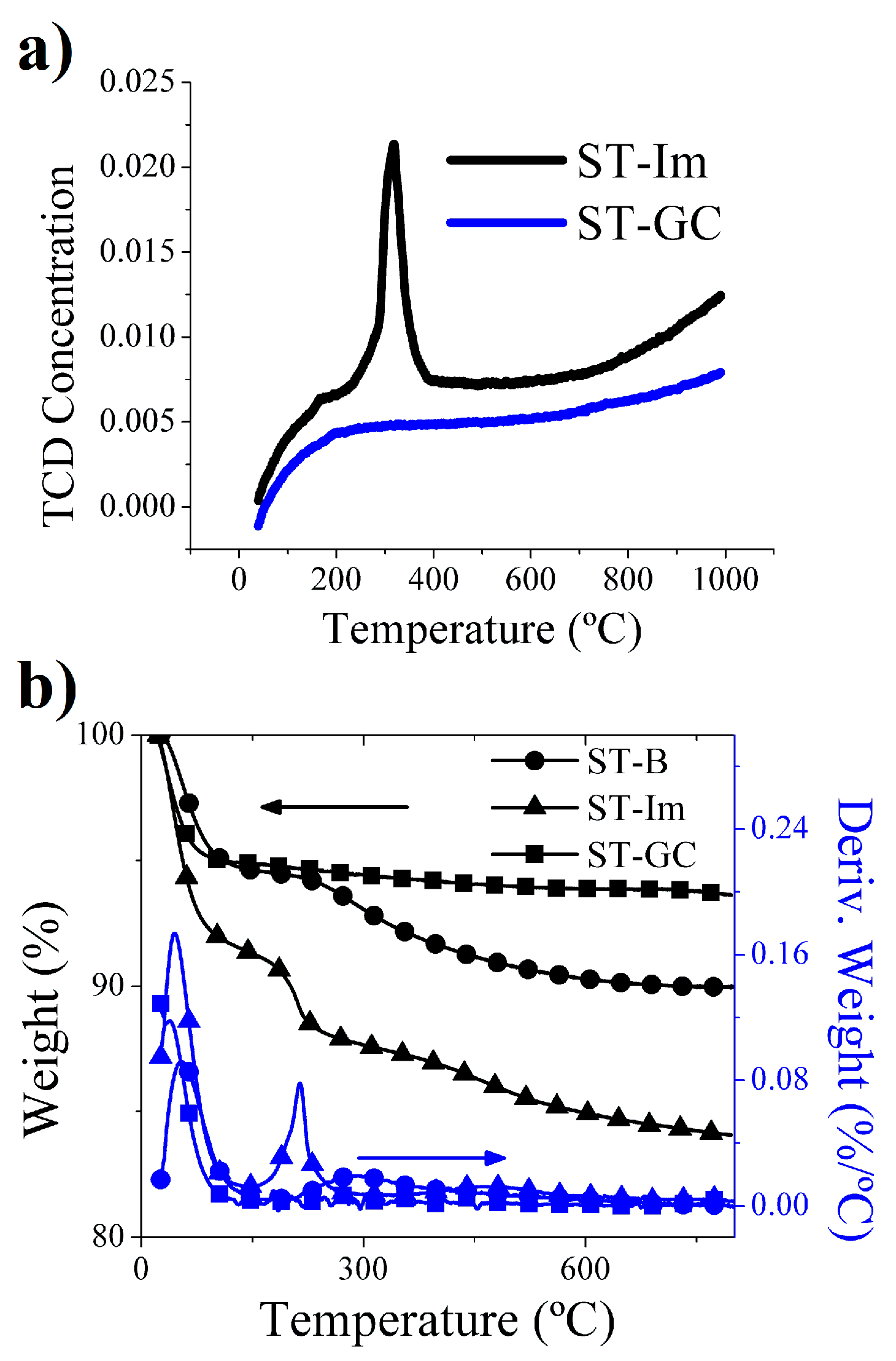
Figure 3.
Thermogravimetric analysis of hybrid tubes obtained by means of catalytic chemical vapor deposition (CCVD) with methane.
Figure 3.
Thermogravimetric analysis of hybrid tubes obtained by means of catalytic chemical vapor deposition (CCVD) with methane.
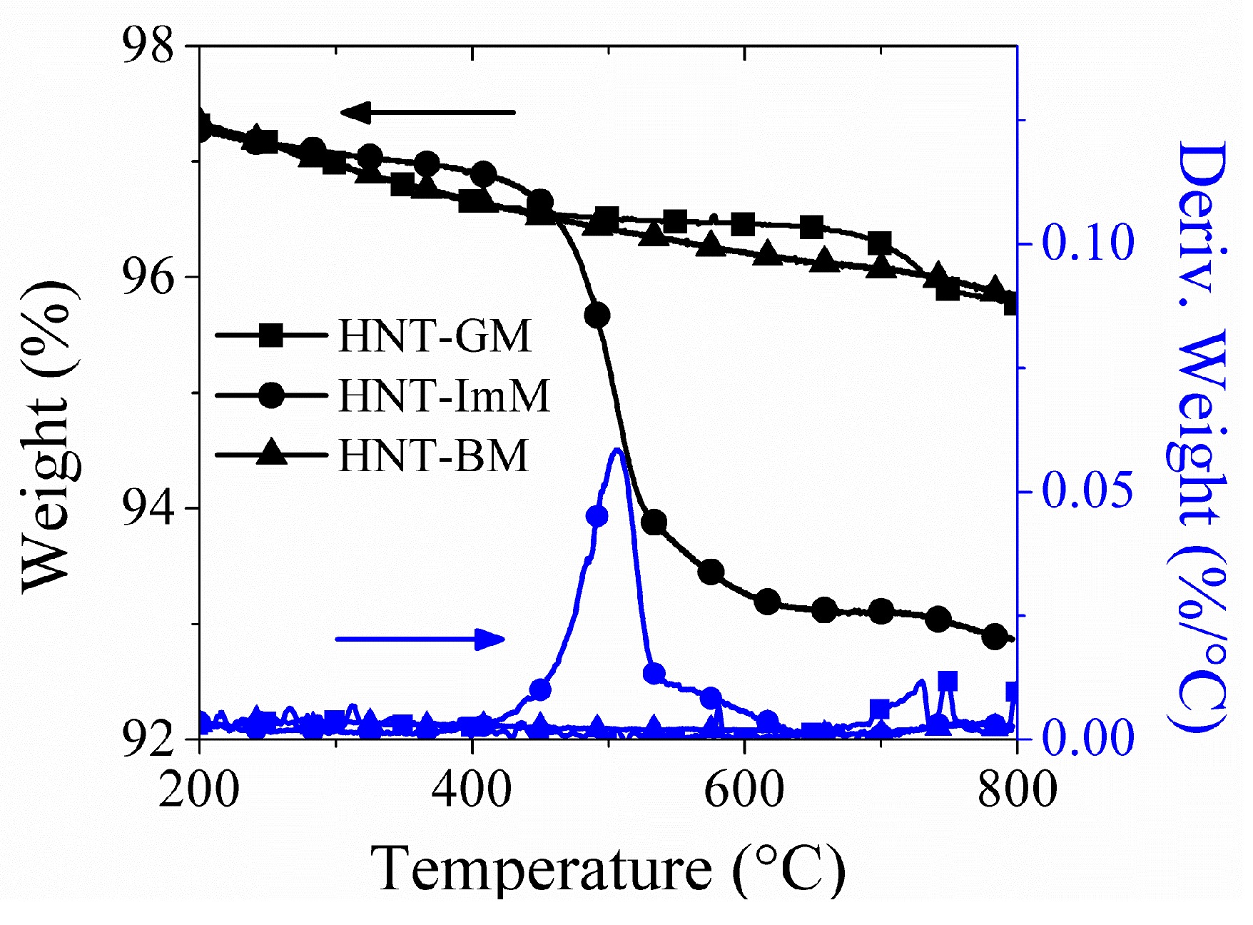
Figure 4.
Raman spectrum of hybrid nanotubes obtained by means of CCVD with methane using cobalt-grafted silica tubes as catalyst (HNT-GM).
Figure 4.
Raman spectrum of hybrid nanotubes obtained by means of CCVD with methane using cobalt-grafted silica tubes as catalyst (HNT-GM).

Figure 5.
(a) Thermogram of the hybrid nanotubes obtained by CCVD with ethene using blank (HNT-BE25) and impregnated (HNT-ImE25) silica nanotubes as support; (b) SEM micrograph of the hybrid submicron tubes HNT-BE25.
Figure 5.
(a) Thermogram of the hybrid nanotubes obtained by CCVD with ethene using blank (HNT-BE25) and impregnated (HNT-ImE25) silica nanotubes as support; (b) SEM micrograph of the hybrid submicron tubes HNT-BE25.
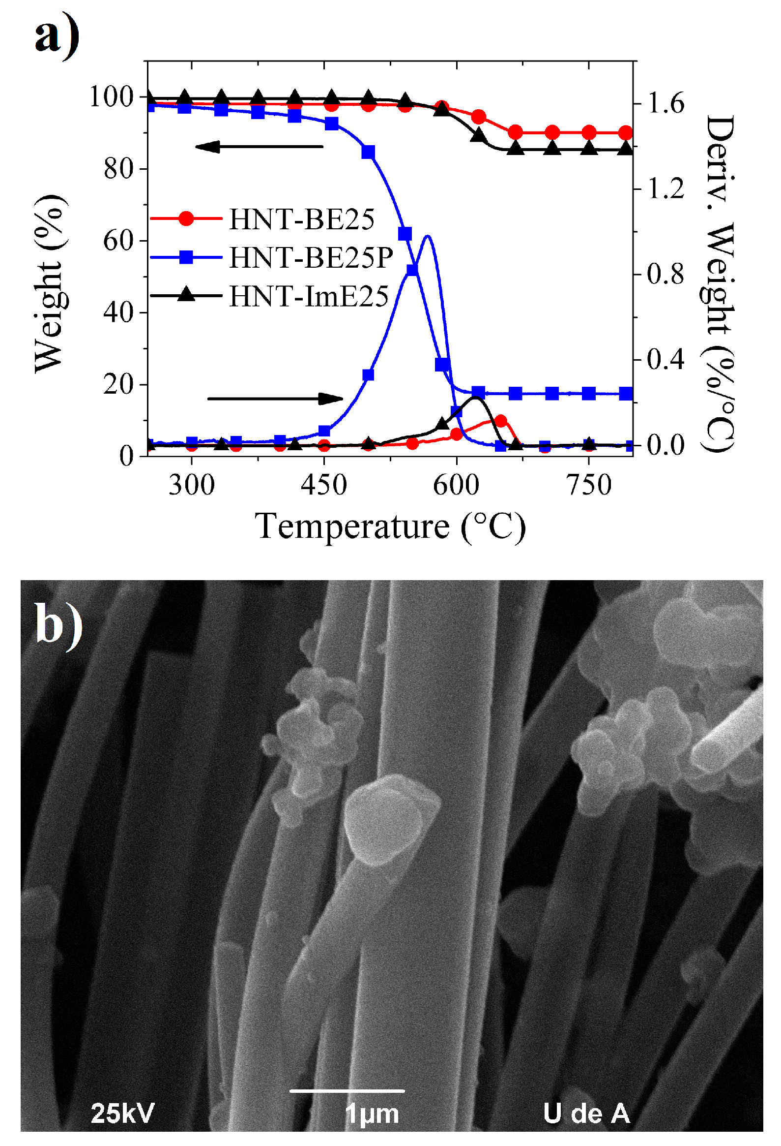
Figure 6.
(a) Scanning electron microscopy (SEM) and (b) Transmission electron microscopy (TEM) micrographs of sample HNT-ImE25.
Figure 6.
(a) Scanning electron microscopy (SEM) and (b) Transmission electron microscopy (TEM) micrographs of sample HNT-ImE25.
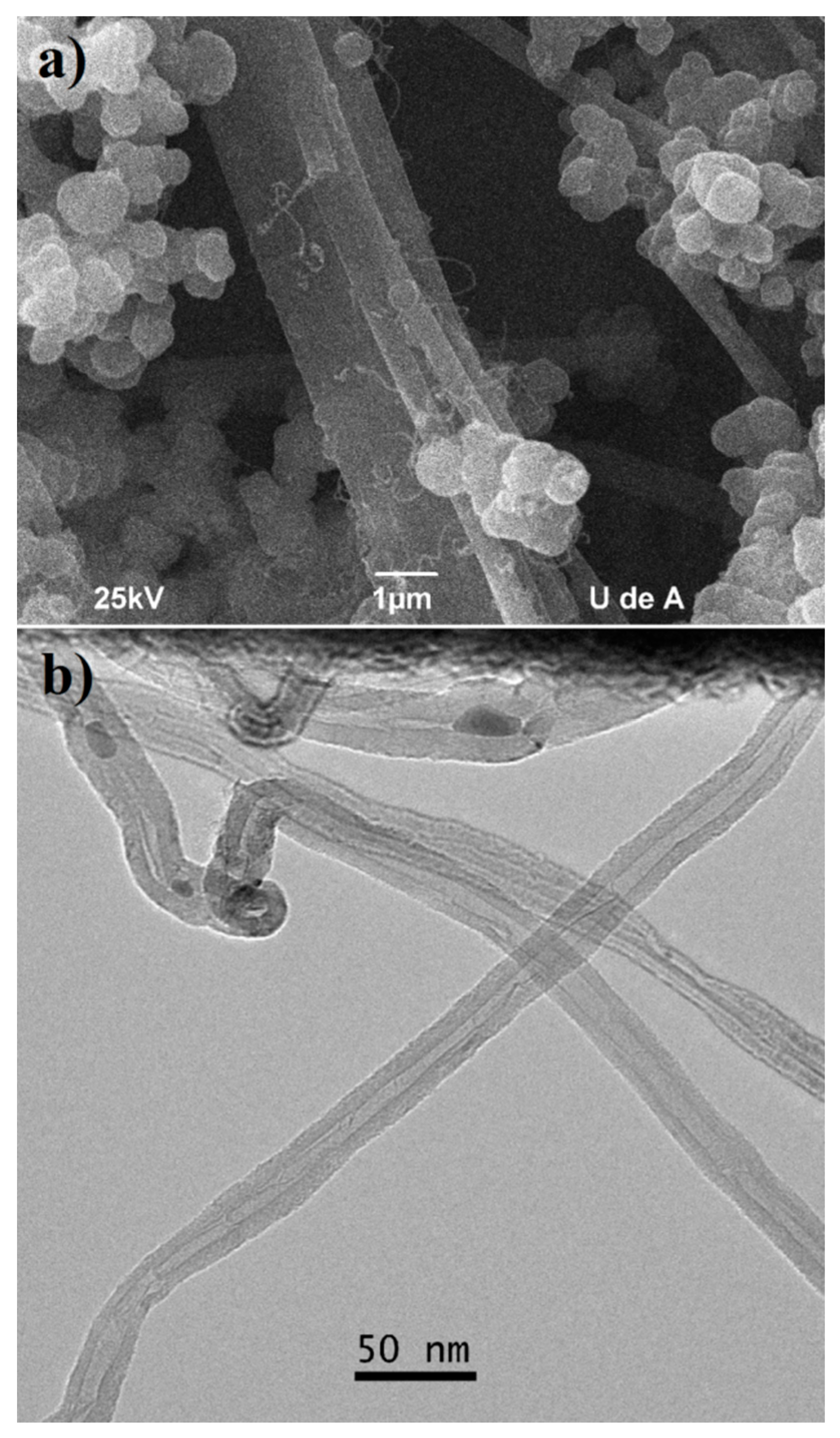
Figure 7.
(a) TEM micrograph of the hybrid nanotubes found after the CCVD process (HNT-GE25); (b) higher magnification showed single-wall carbon nanotubes (SWCNT), multiwalled carbon nanotubes (MWCNT) and a succession of carbon/silica/carbon layers; (c) structures found after silica removal, the square shows a concentric tube and (d) thermogravimetric analysis of the samples, showing the effect of reactive mixtures on the thermal behavior of hybrid tubes.
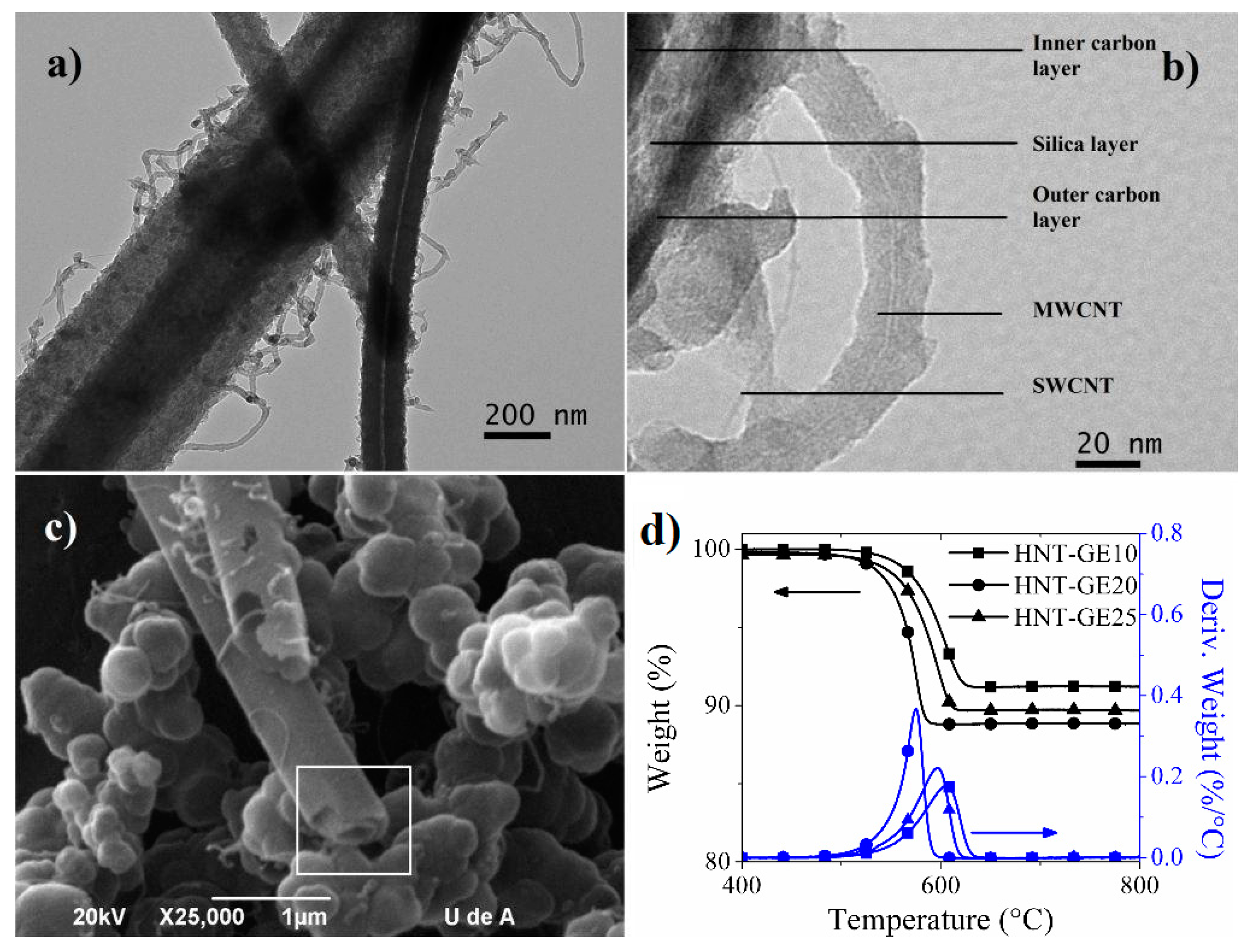
Figure 8.
Raman spectra of the hybrid tubes HNT-GE25.

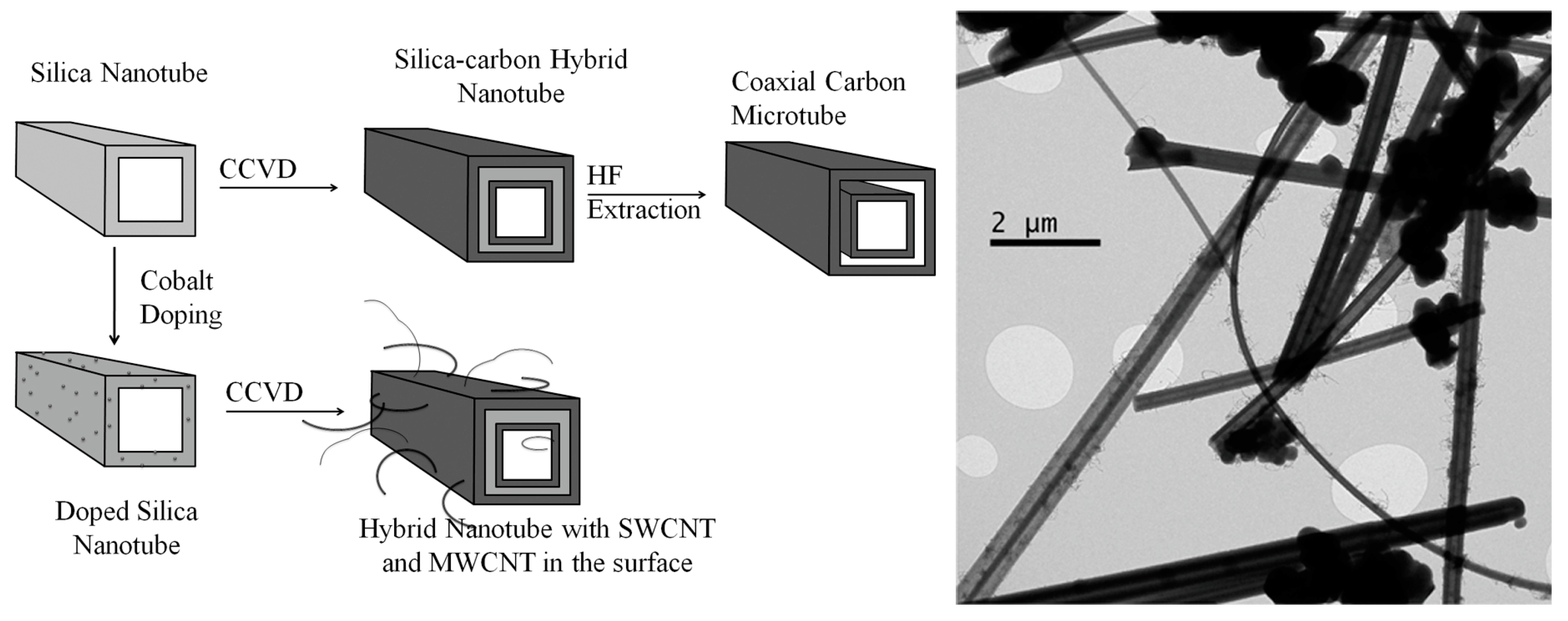
Figure 9.
Schematic representation of the hybrid silica-carbon tubular structures obtained in this study. The coaxial carbon microtube can be observed in the SEM micrograph shown in Figure 7c.
Figure 9.
Schematic representation of the hybrid silica-carbon tubular structures obtained in this study. The coaxial carbon microtube can be observed in the SEM micrograph shown in Figure 7c.


Table 1.
Molar ratios for silica tubes synthesis.
| Sample | Molar Ratio W/TEOS/TA/E * |
|---|---|
| ST_ref | 1:1:0.04:26 |
| STw+ | 2:1:0.04:26 |
| STw- | 0.5:1:0.04:26 |
| STe- | 1:1:0.04:13 |
| STe+ | 1:1:0.04:38 |
| STta+ | 1:1:0.2:26 |
| STta- | 1:1:0.02:26 |
* W = water, TA = Tartaric acid, E = Ethanol.
© 2017 by the authors. Licensee MDPI, Basel, Switzerland. This article is an open access article distributed under the terms and conditions of the Creative Commons Attribution (CC BY) license (http://creativecommons.org/licenses/by/4.0/).
Share and Cite
MDPI and ACS Style
Sepulveda, V.R.; López, B.L. Synthesis of Hybrid Silica-Carbon Tubular Structures by Chemical Vapor Deposition with Methane or Ethene. C 2018, 4, 1. https://doi.org/10.3390/c4010001
AMA Style
Sepulveda VR, López BL. Synthesis of Hybrid Silica-Carbon Tubular Structures by Chemical Vapor Deposition with Methane or Ethene. C. 2018; 4(1):1. https://doi.org/10.3390/c4010001
Chicago/Turabian StyleSepulveda, Victor R., and Betty L. López. 2018. "Synthesis of Hybrid Silica-Carbon Tubular Structures by Chemical Vapor Deposition with Methane or Ethene" C 4, no. 1: 1. https://doi.org/10.3390/c4010001
Note that from the first issue of 2016, this journal uses article numbers instead of page numbers. See further details here.