Article

Experimental Investigation of Finite Aspect Ratio Cylindrical Bodies for Accelerated Wind Applications

1
Nel Hydrogen, Wallingford, CT 06492, USA
2
Department of Mechanical and Aeronautical Engineering, Clarkson University, Potsdam, NY 13699, USA
*
Author to whom correspondence should be addressed.
Fluids 2020, 5(1), 25; https://doi.org/10.3390/fluids5010025
Submission received: 26 January 2020 / Revised: 11 February 2020 / Accepted: 13 February 2020 / Published: 17 February 2020
(This article belongs to the Special Issue Flow-Based Optimization of Products or Devices)

Abstract

:
The placement of a cylindrical body in a flow alters the velocity and pressure fields resulting in a local increase in the flow speed near the body. This interaction is of interest as wind turbine rotor blades could be placed in the area of increased wind speed to enhance energy harvesting. In this work the aerodynamic performance of two short aspect ratio (AR = 0.93) cylindrical bodies was evaluated for potential use in “accelerated wind” applications. The first cylinder was smooth with a constant diameter. The diameter of the second cylinder varied periodically along the span forming channels, or corrugations, where wind turbine blades could be placed. Experiments were performed for Reynolds numbers ranging from 1 × 10⁵ to 9 × 10⁵. Pressure distributions showed that the smooth cylinder had lower minimum pressure coefficients and delayed separation compared to the corrugated cylinder. Velocity profiles showed that the corrugated cylinder had lower peak speeds, a less uniform profile, and lower kinetic energy flux when compared to the smooth cylinder. It was concluded that the smooth cylinder had significantly better potential performance in accelerated wind applications than the corrugated cylinder.

1. Introduction

The power that can be extracted from the wind is primarily driven by three factors, the cross-sectional area that is being used to capture the wind, the velocity of the captured wind, and the power coefficient of the turbine blades. This relationship is described by:
P = 1 2 ρ π R 2 U f s 3 C p o w
Here Cpow is the coefficient of power for the wind turbine, Ufs is the free stream wind speed, and R is the rotor radius [1]. Note that in this work Cp is used to define the pressure coefficient rather than the coefficient of power. One can, therefore, increase the harvested power by increasing the blade radius, the wind speed, or the coefficient of power, which is representative of the aerodynamic efficiency of the wind turbine. Equation (1) indicates that the rotor area is a strong driver of the power of a wind turbine. This has led to increased rotor sizes, especially for commercial scale wind turbines. However, wind turbine sizes are ultimately bounded by structural limitations and other practical considerations such as the need to transport parts. Power is also a function of the coefficient of power of the system which has an upper limit defined by the Betz limit (59.3%) for free wind turbines, limiting potential gains through increased aerodynamic efficiency.
Equation (1) indicates that a wind turbine’s extracted power has a cubic relationship with wind speed. This leads to the strategy of increasing the velocity of the wind at the rotor plane to increase the power extraction. Increased wind speed is typically accomplished by siting turbines in locations with high wind speeds or by increasing the tower height. This, however, limits the number of economically viable siting locations. Alternately, one could attempt to modify the local wind stream to achieve higher velocities at the rotor plane. This approach is attractive in that relatively small changes in the local wind speed can lead to significant increases in harvested energy.
“Accelerated wind” is a general term for such strategies and is normally accomplished by adding a structure near the rotor to locally increase the flow velocity. The most common example is seen in diffuser augmented wind turbines (DAWT). A DAWT’s structure lowers the pressure downstream of the blades to draw a greater mass of air through the rotor plane and thus generate more power than a similarly sized horizontal axis wind turbine (HAWT) [1,2,3,4,5,6,7,8,9,10]. A less explored accelerated wind concept is to place rotors near structures that increase the local wind speed. Examples of this include building augmented wind turbines [11,12,13] and specially designed tower structures [14,15,16]. This study explores the concept of placing wind turbine rotors next to a cylindrical structure, see Figure 1. The cylindrical structure serves to act as both the wind turbine tower and a method to increase the velocity at the rotor plane.
Duffy and Jaran [12] reported on what they named a “toroidal accelerator rotor platform” (TARP). The TARP concept used a toroidal channel around the outside of a cylinder to accelerate the wind into rotor blades that were mounted in the channel. The TARP was intended to be either an add-on attachment to grain silos, water towers, etc. or as a standalone structure. This concept was extended to the WARP, or wind amplified rotor platform, consisting of a number of stacked TARP modules [13]. A prototype was built and briefly tested in Belgium; however, a viable commercial product does not exist today.
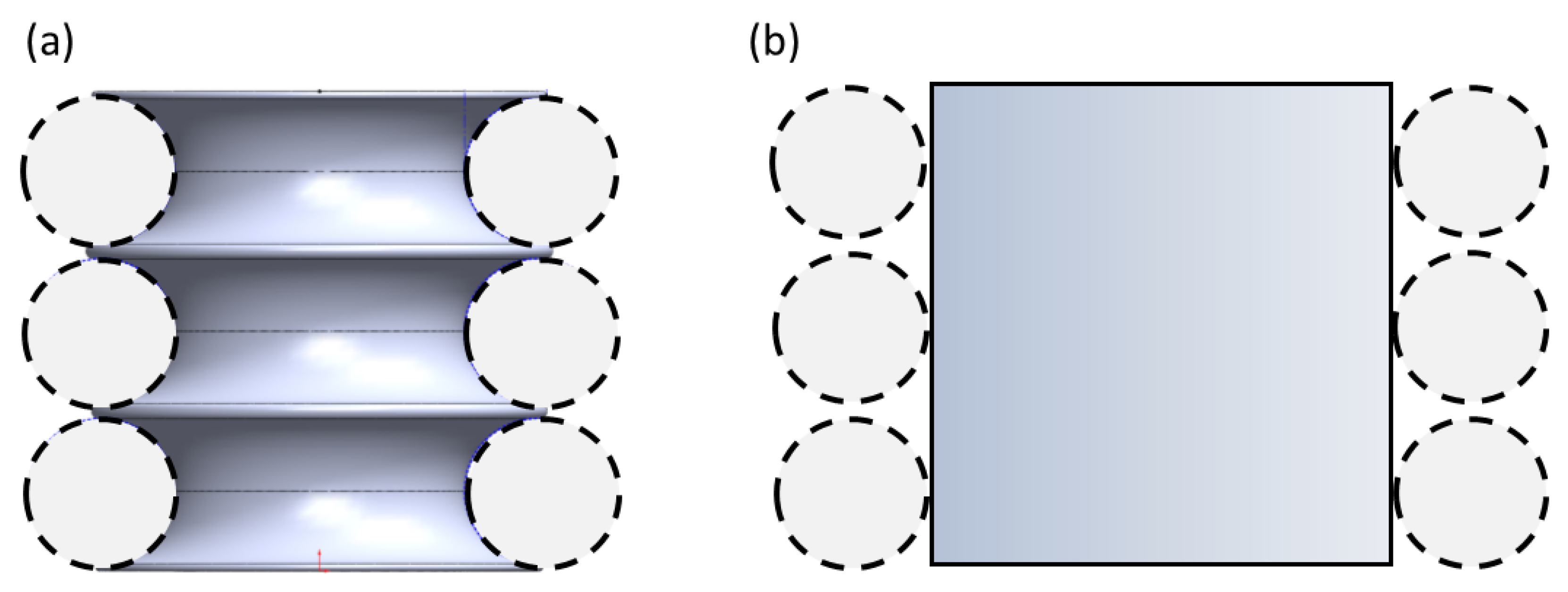
A similar concept, the Optiwind “Accelerator Platform”, shown in Figure 1a, formed the motivation for the current study. This concept was a finite span (aspect ratio, AR = 0.93) corrugated circular cylinder where the rotor blades would also sit in isolated channels. The channels were conceived of as aerodynamic structures to direct the wind into the wind turbine blades, which would also isolate the wind turbine blades from each other. This is strategically different from DWATs in that the channels were not intended to be traditional diffusers, but more specifically as flow directors. Flow acceleration was provided by the surface curvature. This concept was the motivation for the first model used in the current study. The second model, shown in Figure 1b, was a smooth circular cylinder with the same aspect ratio and a diameter equal to the outer diameter of the corrugated cylinder. The location of the rotor placement for both designs is indicated by the dashed circles. Both models were intended to accelerate the wind prior to entering rotors; however, the smooth cylinder lacked the “flow directing” channels as shown. The high level goal of the project was to design a mid-range, scalable wind turbine for the renewable energy market [15]. In both cases the number of stack turbines, three shown in Figure 1 and used for testing, could be chosen arbitrarily depending on the power requirements.
This work details experiments performed on the two tower models: a 1:80 scale model of the Optiwind Accelerator Platform (i.e., the “corrugated cylinder model”) and a smooth circular cylinder with the same aspect ratio as the corrugated model. The surface pressures and tangential velocity, Vθ (r), profiles were acquired experimentally for both platform models. The location and magnitude of the minimum pressure coefficient (Cp,min) and the mean flow velocities were used as metrics in determining the effectiveness of the potential designs for accelerating the flow. The minimum pressure coefficient, Cp,min, serves as one basis for discussion of the performance in this work in two ways. First, the location of the Cp,min is indicative of where the surface flow curvature has changed and the flow is no longer following the surface shape. It can be used to determine if the separation point has moved forward or aft between cases. Second, the magnitude of Cp,min correlates with the increase in flow velocity, and it can again be used comparatively between cases.
The motivation for this work was to assess the potential of the two shapes for accelerated wind applications. The goal of the current work was to compare, in a quantitative manner, the flow around low aspect ratio cylinders with smooth and corrugated surfaces. Within the larger project, the results of this study were used to down select the platform shape and guide the continued design/development of the prototype wind accelerator platform within the larger project. It is acknowledged that the presence of rotors, which were not investigated in this work, would change the flow conditions around both the corrugated and smooth cylinders. This effect is the subject of future studies for the following reasons. First, rotors are typically designed to provide a specific pressure drop that optimizes the power extraction. Because this study was used to down select the platform geometry, the rotors have not yet been designed. Second, this study provides a canonical case comparing short aspect ratio cylinders with and without surface corrugations. These conditions, without the rotors, therefore represent the upper limit on the potential performance.

2. Materials and Methods

2.1. Experimental Models and Facility

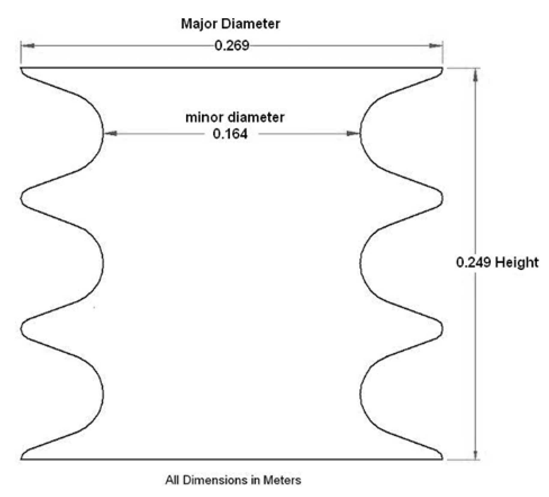
The corrugated cylinder was constructed using stereolithography as a 1:80 scaled model of the proposed Optiwind Accelerator Platform design with three rows of corrugations, as shown in Figure 2. The key dimensions of the model were as follows: major diameter, Dmaj = 0.269 m; minor diameter Dmin = 0.164 m; length, L = 0.249 m; and the aspect ratio based on the major diameter L/Dmaj = 0.93. Pressure taps were added circumferentially along the minor diameter (i.e., in the “valley” of the channel) of the model and along the corrugation walls, as shown in Figure 3, for all three channels. The surface of the corrugated cylinder was sanded to smooth the steps in the surface resulting from the stereolithography fabrication.
A smooth cylinder with the same diameter as the major diameter and aspect ratio of the corrugated cylinder provided a second potential platform design as well as a canonical baseline reference case. The smooth cylinder was fabricated from a 0.27 m diameter PVC pipe cut to the same length as the corrugated cylinder, which provided an aspect ratio equal to the platform model, L/D = 0.93. Pressure taps were machined into the cylinder at the mid-height.
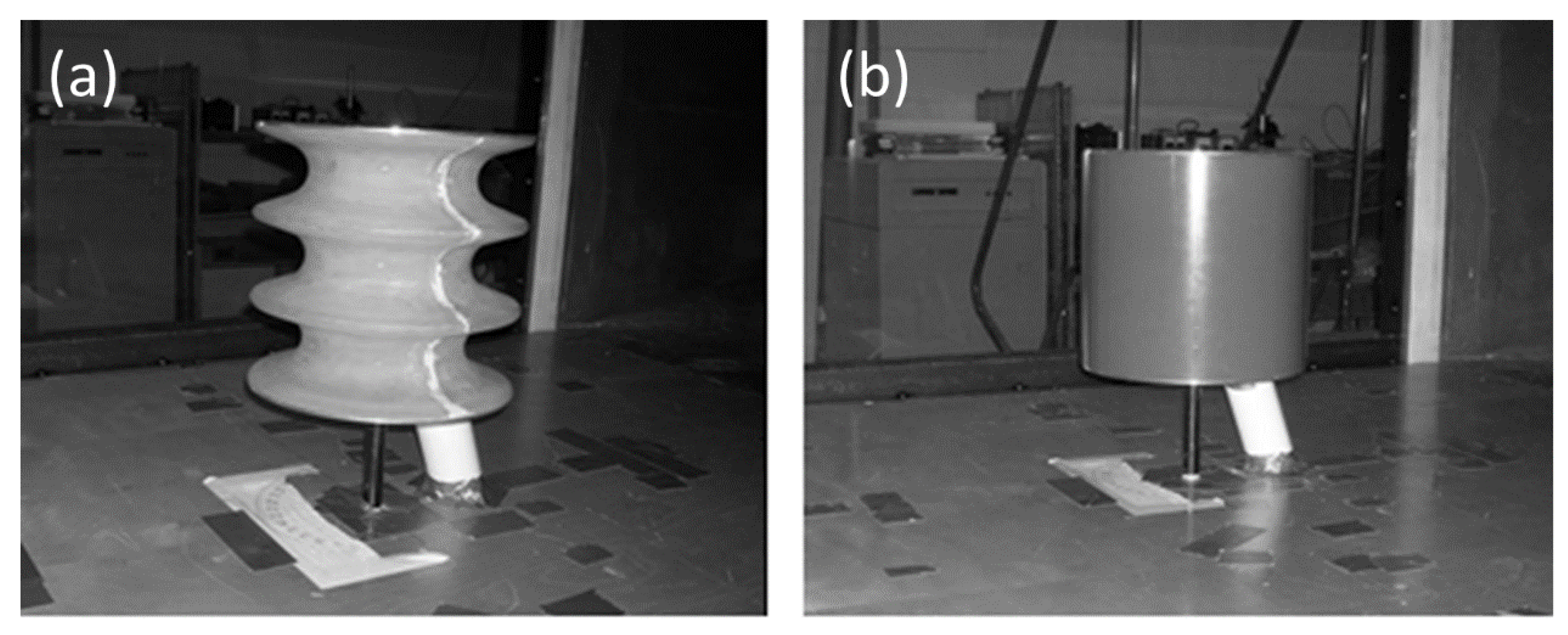
Experiments were performed in the Clarkson University High Speed Aerodynamic Wind Tunnel. The tunnel is an open loop tunnel with a 1.2 × 0.9 × 1.8 m long test section. The tunnel blockage due to the models was 6.7% based on the major diameter and length of the corrugated cylinder model. Experimental flow speeds ranged from Ufs = 10 to 50 m/s. The turbulence level of the tunnel free stream was measured via hotwire anemometry to be approximately 1.2% within the velocity range investigated. The Reynolds number was computed based on the major diameter of the corrugated cylinder and the test section free stream speed. Experimental Reynolds numbers covered a range of Re = Ufs Dmaj/υ = 1.9 × 10⁵ to 8.9 × 10⁵ for this study. It is noted that the Reynolds number for the full scale device was expected to be nominally 50–100 × 105. The upper end of the experimental Reynolds number was limited in this work by the flow facility (i.e., cross sectional area of the test section and maximum flow speed). While this was approximately an order of magnitude lower than the device Reynolds number that motivated the study, the results show a decreasing dependence on the Reynolds number, and the results were expected to be qualitatively similar and therefore informative. The lowest Reynolds number was investigated to allow for Reynolds number trends to be investigated. Both models were placed in the wind tunnel with a 0.15 m vertical offset from the bottom floor of the test section, as shown in Figure 4. The tops and bottoms of the models were closed.

2.2. Pressure Measurements

The models contained pressure taps with 1 mm diameter openings at the surface starting at the leading edge (θ = 0°) and extending around the diameter of the models in 10° increments. Stainless steel tubing (1.58mm outer diameter, 1.32 mm inner diameter) was pressed into each tap to allow for connection with the pressure transducer via Tygon tubing. The corrugated cylinder model also had rows of pressure taps along the channel walls at ϕ = 42° and 98° up from the horizontal as shown in Figure 3. Pressure surveys were conducted using an Omega model PX653-10BD5V pressure transducer with a ±2.5 kPa range. Data were acquired with a National Instruments PCI-6024E 12 bit A/D card. Each pressure measurement consisted of 96,000 data points at a sampling rate of 2400 Hz. A ScaniValve solenoid controller was used to index through the model pressure taps sequentially after sampling at a given location was completed. Uncertainty in the pressure measurements was estimated to be 0.025 kPa, which corresponded to an uncertainty level in the reported pressure coefficients of Cp = ±0.03.
The pressure data reported in this work are the average surface pressure values in non-dimensional form. The pressure coefficient, CP, was calculated using:
C p = P ¯ S P ¯ S , T u n n e l 1 2 ρ U f s 2
where P ¯ S is the average pressure at a tap location and P ¯ S , T u n n e l is the static pressure in the test section upstream of the model. The dynamic pressure of the free stream was measured using a pitot-static probe upstream of the models.

2.3. Hot-Wire Measurements

Velocity surveys were taken around the models using a DISA type 55M01 Constant Temperature Anemometer (CTA) with a DANTEC 55P14 single-wire probe. The hot-wire sensor utilized a 5 μm tungsten wire with a 1mm active length. Data were acquired with a National Instruments PCI-6024E 12 bit A/D card. Hot-wire data were sampled at 12,000 Hz for 30 s to provide 360,000 measurements. The hot-wire probes were pre- and post-calibrated to ensure the sensor did not drift during use. The uncertainty in the hot-wire measurements was estimated to be ±0.058 Vθ/Ufs. Velocity profiles were performed by traversing the probe radially outward at 13 different angular locations around the model over the range of θ = 0° to 180° in 15° increments.

3. Results

3.1. Review of Flow Around Circular Cylinders

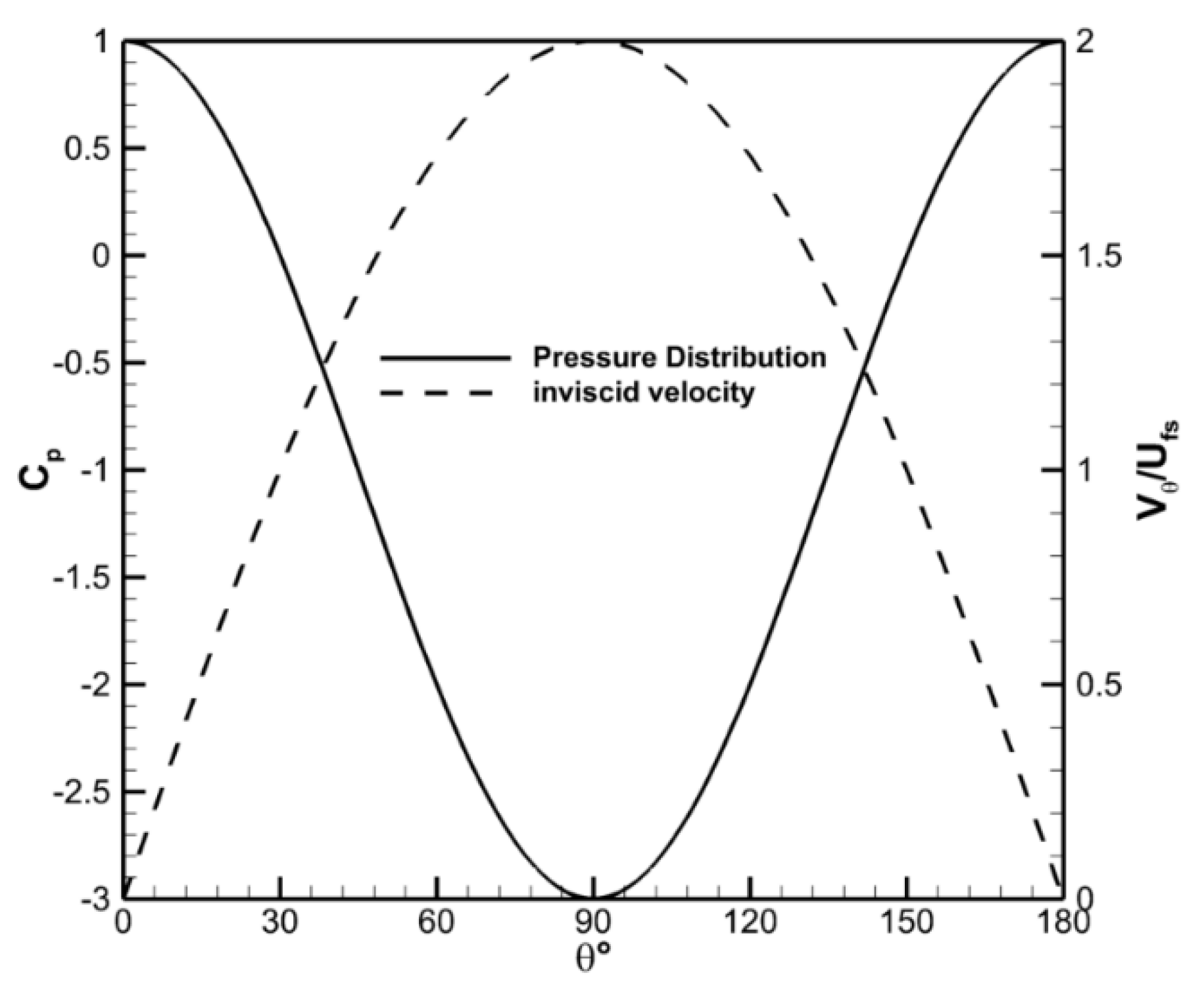
The inviscid solution to flow around a 2D circular cylinder [17] provides the limiting case for the current study. The solid line in Figure 5 shows the surface pressure distribution, while the dashed line shows the associated tangential surface velocity, Vθ, distribution for the inviscid flow around a cylinder. The leading edge of the cylinder is defined as θ = 0°. In the absence of viscosity, the peak speed around a circular cylinder is Vθ/Ufs = 2 and is located at θ = 90°. This corresponds to a minimum pressure coefficient of Cp,min = −3 at the same angular location. Equation (1) indicates that a factor of 2 increase in the wind speed would result in a factor of 8 potential increase in the harvestable power at the surface of the cylinder. It is worth noting that the actual increase in power would be lower than a factor of 8 as Vθ decreases in the radial direction even for the inviscid case; therefore, the actual increase in power would depend on the radius of the wind turbine blades.
Past results for circular cylinders without end effects [18,19,20,21] show that for Reynolds numbers of practical importance, the flow separates and forms a wake downstream of the cylinder. The location of the separation generally begins at about θ ≈ 70° and moves aft (i.e., increasing θ) with the increasing Reynolds number to an angle of θ ≈ 120°, as shown in Figure 6. These results also show that the wake region becomes smaller with the increasing Reynolds number. The Re = 8.5 × 10⁵ case shown in Figure 6 does not follow the Reynolds number trends as Cp,min is significantly lower and further aft for this case than for the higher Re = 3.6 × 10⁶ case. This is due to the formation of a separation bubble at the surface of the cylinder, which occurs in a critical Reynolds number range [18].
Results for finite aspect ratio cylinders with two free ends in the Reynolds number range of the current experiments are more limited as most studies are concentrated on cantilevered finite aspect ratio geometries [22,23,24]. Zdravkovich et al. [25] investigated the pressure distributions around circular cylinders of finite aspect ratio with two free ends for the Reynolds number between 0.6 and 2.6 × 10⁵. Data from that work for a L/D = 1 and Re = 2.6 × 10⁵ showed Cp,min ≈ −1.6 occurring at θ ≈ 70°. The angular location of Cp,min was consistent with the data from Achenbach [18] with a difference of approximately 33% in Cp,min. The work in this study is compared with the results of Achenbach to provide comparative analysis on the effect of the short aspect ratio on the pressure distribution.

3.2. Pressure Surveys

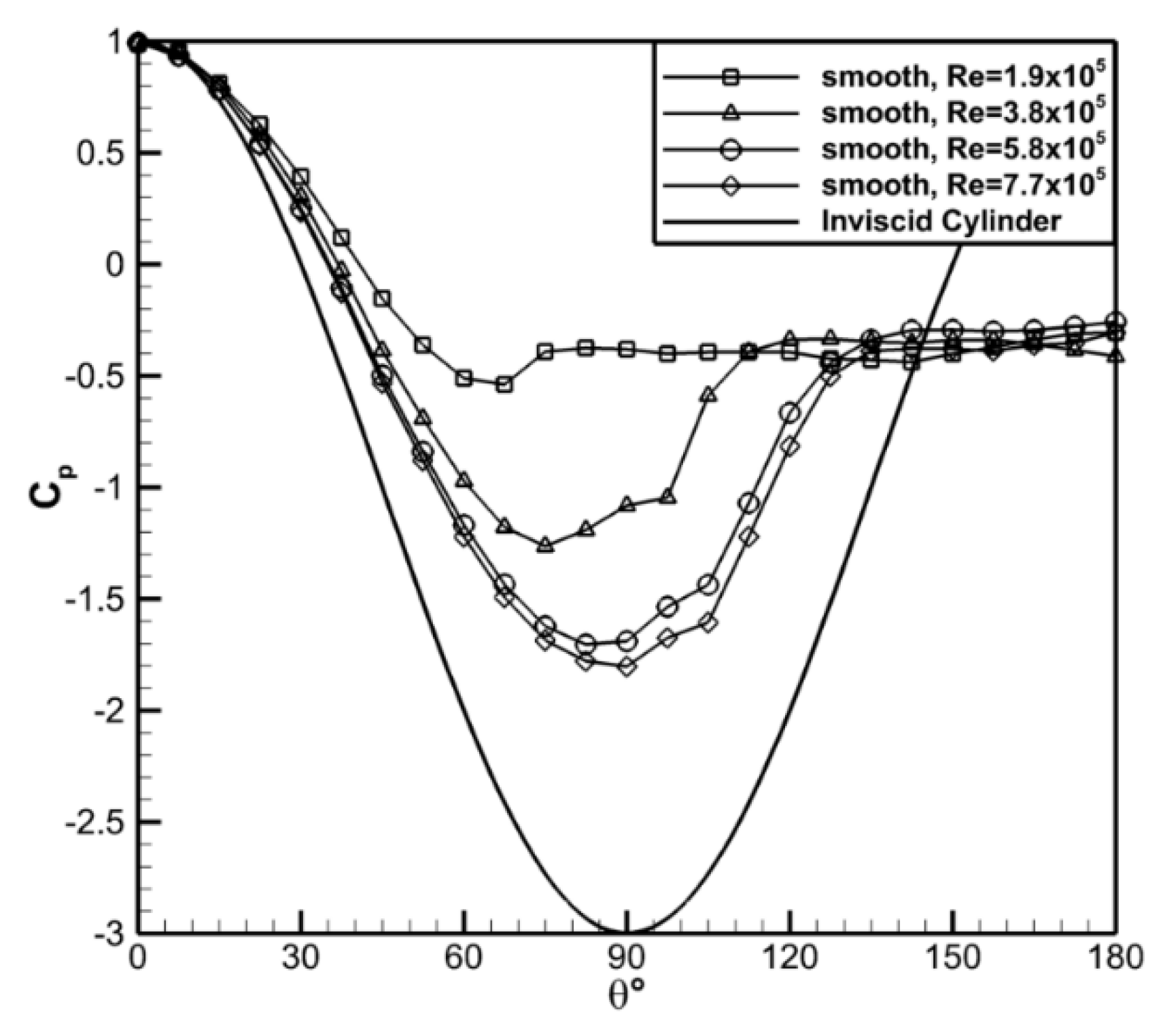
Figure 7 shows the surface pressure distribution along the centerline of the smooth cylinder for the Reynolds number range investigated. The data showed that Cp,min decreased and its location moved aft as the Reynolds number increased, consistent with the trends for the 2D cylinder. At Re = 1.9 × 10⁵ the surface pressure deviated almost immediately from the inviscid profile and had a minimum pressure coefficient of Cp,min = −0.5 at θ ≈ 68°. The pressure coefficient recovered slightly to a nominally constant value of Cp = −0.4 after this point. The location and value of Cp,min were indicative of laminar flow around a cylinder. For the Re = 7.7 × 10⁵ case the minimum pressure coefficient was found to be Cp,min = −1.8 at θ ≈ 90°, more consistent with turbulent flow. The dependence on the Reynolds number appeared to be more significant at lower Reynolds numbers and was likely a result of the transition from laminar to turbulent flow.
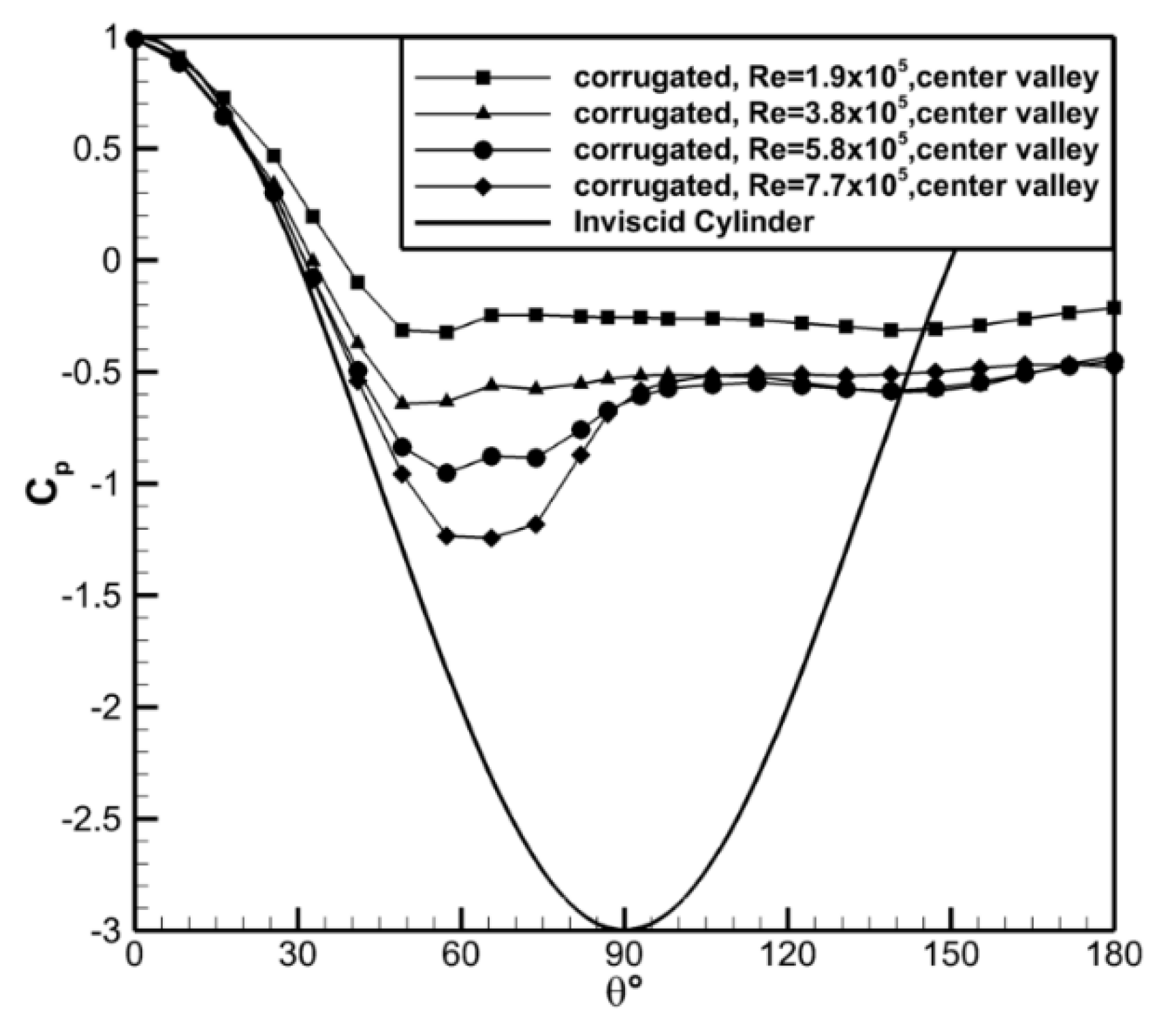
The results for the valley of the center channel for the corrugated cylinder are shown in Figure 8. There was similar Reynolds number dependence observed for this model. The minimum pressure coefficient, Cp,min, decreased with the increased Reynolds number going from Cp,min ≈ −0.33 at Re = 1.9 × 10⁵ to Cp,min ≈ −1.24 at Re = 7.7 × 10⁵. While the location of Cp,min shifted farther aft on the cylinder with increasing Reynolds number (θ ≈ 54 to 66°), this shift was less significant than was observed for the smooth cylinder. In the separated wake of the corrugated cylinder, the pressure coefficient was nominally uniform for all cases at Cp = −0.52 except for the lowest Reynolds number case for which Cp = −0.28 in this region. This case also showed very little pressure recovery after the location of the minimum pressure.
Comparison of the two current cases to previous data [18] are shown in Figure 9. The current data for the low aspect ratio smooth cylinder indicated that the pressure distribution was significantly altered by the lower aspect ratio of the model in the current study throughout the Reynolds number range investigated. Specifically, Cp,min was lower and its location more aft for the infinite span compared to the finite span case. These observations indicated that end effects caused earlier separation, which reduced the pressure change on the cylinder surface. Data taken were also acquired with end plates (1.5D) on the finite aspect ratio smooth cylinder. These plates were insufficient to counteract end effects at low Re, as can be seen in Figure 9a; however, at the higher Re, shown in Figure 9b, the surface pressure profiles are more similar to the reference data of Achenbach [18]. The high Reynolds number cases for the current data and the reference data were both in the critical Reynolds number range with flow separation and reattachment; however, the gradient in the pressure distribution following separation was lower for the finite aspect ratio cylinder. This implied that the separation and reattachment region was likely smaller for the finite aspect ratio case in the critical Reynolds number range.
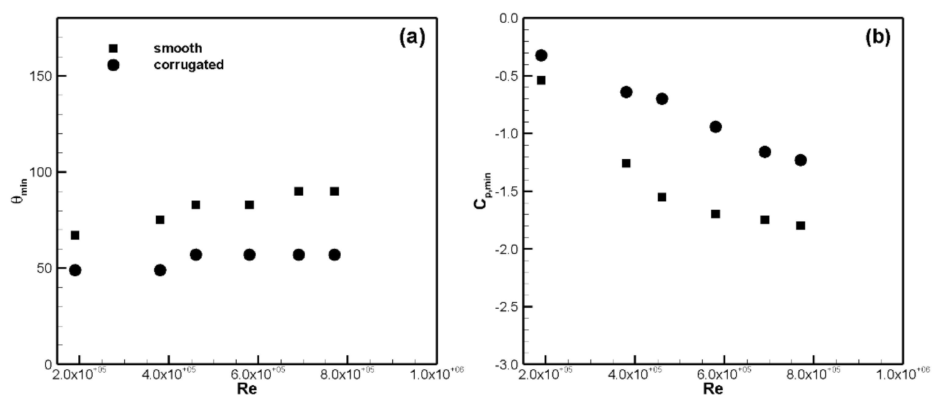
Comparison of the corrugated and smooth cylinders showed Cp,min was significantly lower for the smooth cylinder when compared to the corrugated cylinder, as shown in Figure 9. The location of the measured minimum pressure and the minimum pressure coefficient, to the spatial resolution of the current data, are shown in Figure 10 to highlight the difference between the models. The location of the minimum pressure, θmin, was earlier and the value of Cp,min was higher for the corrugated cylinder versus the smooth cylinder. For example, at Re = 7.7 × 10⁵ the values were −1.25 vs. −1.80 for Cp,min and 57° vs. 90° for θmin. The pressure surveys indicated that the separation was earlier for the corrugated model and was suggestive that the drag would be higher for case as well. Limited direct drag measurements, not shown in this work, measured a drag coefficient of Cd = 0.95 for the corrugated cylinder compared to Cd = 0.60 for the smooth cylinder at Re = 7.7 × 10⁵ supporting the results of the pressure surveys. The higher relative Cp,min values were suggestive that the flow speeds, and therefore the degree of flow acceleration, for the corrugated model were lower than for the smooth cylinder. This was important for the motivating accelerated wind application in that it indicated that the smooth cylinder would perform better. The trends in these results would be expected to hold for the real world application, which would include wind turbine blades, though the magnitudes would be expected to be different.
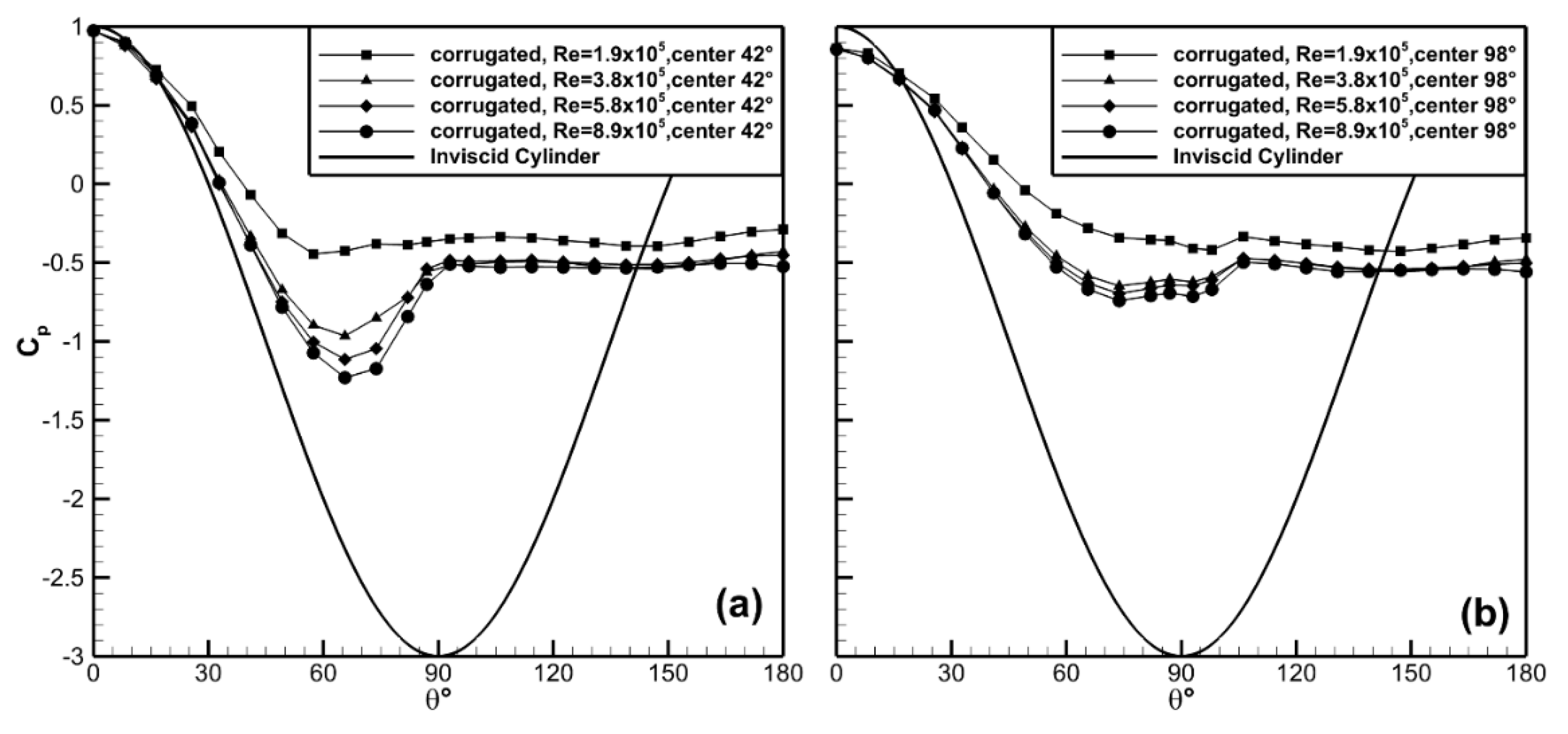
The surface pressures at ϕ = 42°, 98° up the side wall of the corrugated cylinder model are shown in Figure 11. The Reynolds number trends observed in the channel valley continued along the channel walls with Cp,min decreasing with increasing Reynolds number. At ϕ = 42° up the channel wall the location of Cp,min moved from θ ≈ 57° at Re = 1.9 × 10⁵ to θ ≈ 65° at Re = 3.8 × 10⁵. Beyond this Reynolds number the separation point remained at nominally the same angular location. Similar trends were observed at ϕ = 98° up the side wall. It is interesting to note that stagnation conditions, Cp < 1 at θ = 0, were not observed at the θ = 98° location indicating the leading edge flow field was quite complex and three dimensional.
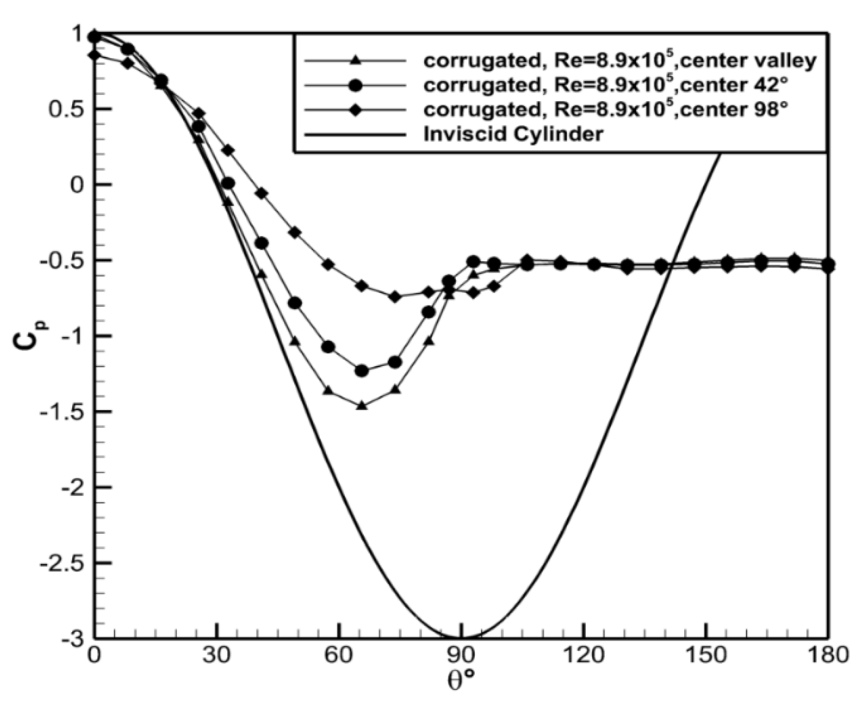
The pressure distributions along the sidewalls are compared in Figure 12. The minimum pressure coefficient, Cp,min, increased from Cp,min = −1.46, in the valley, to Cp,min = −1.23 at ϕ = 42° and Cp,min = −0.74 at ϕ = 98°. The angular location of Cp,min was the same for the valley and ϕ = 42° but moved slightly further aft at the ϕ = 98°. The pressure at the leading edge also showed a dependence on the wall location. In the channel valley, Cp = 0.99 indicating that the tap was at or near a stagnation point. The pressure coefficient was slightly less than this (Cp = 0.97) at ϕ = 42°. In contrast, at ϕ = 98°, Cp = 0.85 for the leading tap. The data show that the flow approached stagnation conditions in or near the valley bottom. The pressure coefficients were uniform in the wake region. The magnitudes of Cp show that the surface pressure was three dimensional within the channels. This is suggestive that the flow acceleration was most prominent in the valley region and decreased towards the side walls of the channel. Note that only a single Reynolds number is shown in Figure 12 for brevity; however, the qualitative trends were consistent for all Reynolds numbers investigated.
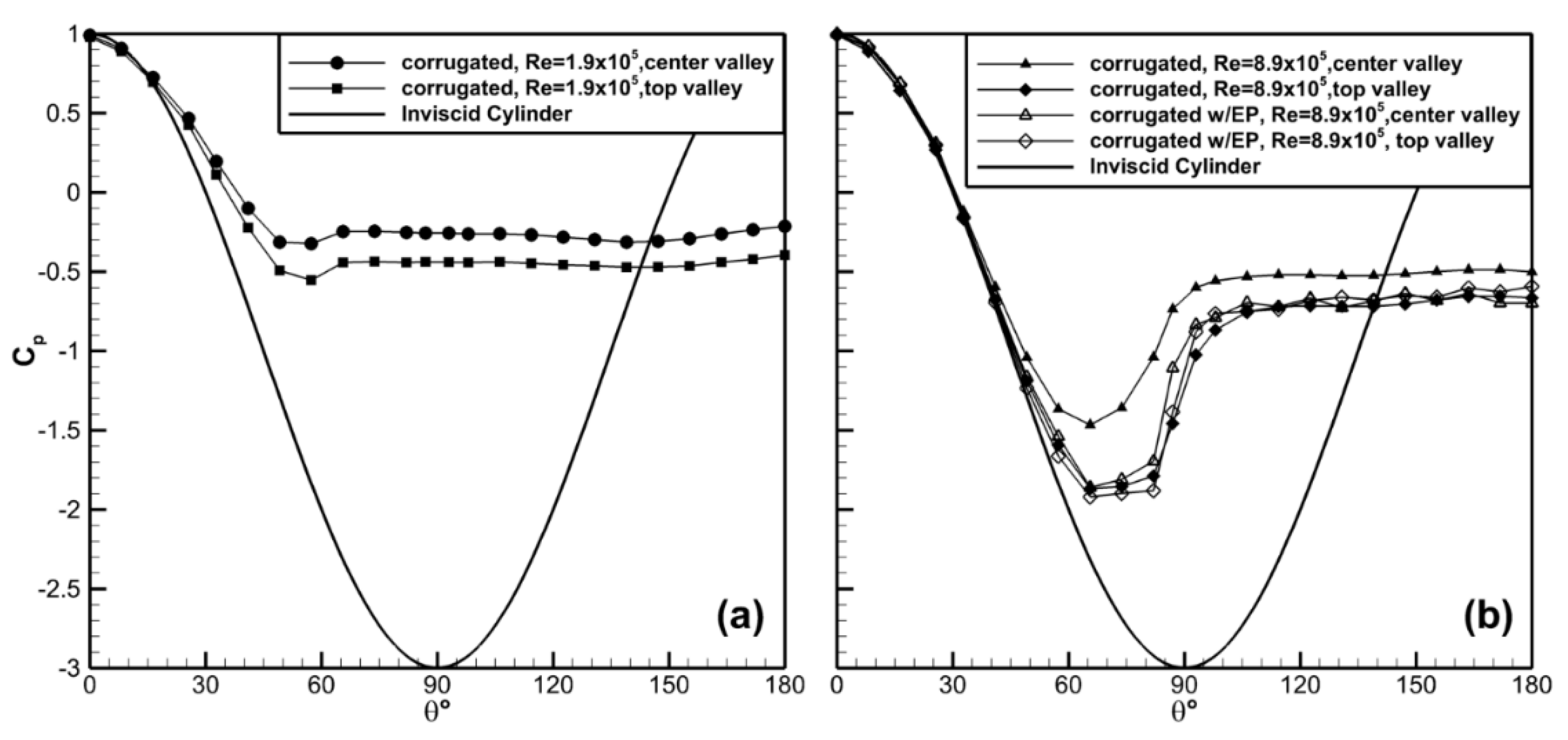
The corrugated cylinder had three channels along the axis of the model allowing for comparison of end versus interior channels. The pressure distribution in the valleys of the center (interior channel) and top channel (end channel) is shown in Figure 13. Significant differences between the interior and end channels were observed. The end channel had lower Cp values at all surface locations and for all Reynolds number cases indicating the end channels had higher potential for energy harvesting compared to interior channels. For example, Cp,min = −1.86 for the top channel, and Cp,min = −1.46 for the center channel at Re = 8.9 × 10⁵. A similar trend was observed for the Re = 1.9 × 10⁵ case with Cp,min lower for the top channel (−0.55 vs. −0.32).
The difference between the two cases was caused by the channel boundary conditions, which were significantly different between the top and the middle channels. The interior channel had nominally symmetric boundary conditions due to the existence of channels above and below. The end channel had different boundary conditions on either side. The lower portion of the top channel was common with the upper portion of the center channel; however, the top portion of the upper channel was bounded by the free stream allowing air flow to go over top of the model. It was interesting to note that these end effects encountered by the top and bottom channels enhanced the performance of the flow dropping Cp,min in the edge channels. The data suggested that the separation was delayed for the end channels resulting in the continued decrease in Cp, which for the intended application would be beneficial. Data with end plates, shown in Figure 13b, confirmed that end effects were responsible for the differences in the surface pressures in the center channel, though the end channel saw minimal improvement with the addition of the plates. The end plates did not appear to alter the pressure on the downstream side of the corrugated cylinder indicating that drag would likely continue to be high for this model.

3.3. Velocity Surveys

Velocity surveys were conducted with single-wire hot-wire probes around the smooth and corrugated cylinders. The probe was oriented at each angular location such that it measured the azimuthal velocity component, Vθ(r). The azimuthal velocity was of primary interest in this study as it is the velocity component normal to the intended rotor plane. Velocity surveys were conducted normal to the surface (i.e., in the radial direction) at 15° increments around the cylinder starting at the leading edge, θ = 0°. The data for the smooth cylinder were acquired at the mid-height of the cylinder, while the data for the corrugated cylinder were acquired along the center channel valley of the model. We note that both measurement locations were expected to have small relative spanwise velocity components due to the presence of the corrugations and/or symmetry. The radial velocity component was also expected to be small outside of the model wakes, which were beyond the expected placement of the rotors.
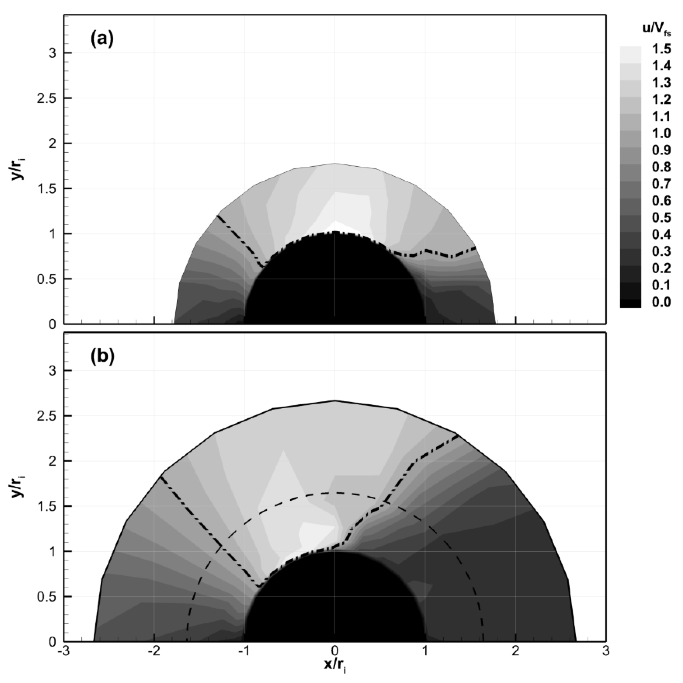
Results of the velocity surveys are shown in contour form in Figure 14 for the Re = 7.7 × 10⁵ case, which was closest to the expected operational Reynolds number. The dash-dot-dot line in the figure marks the boarder where the flow speed was equal to the free stream. This was included to differentiate the regions where the flow speed was either above or below the free stream value. Both cases show deceleration as the flow approached the leading edge, as expected. The flow then accelerated around both the smooth and corrugated cylinders; however, the velocity fields were quantitatively different for the two models. The data clearly show that the location of the peak flow speeds was shifted to higher angles (i.e., closer to θ ≈ 90°) for the smooth cylinder. The peak speed for the smooth cylinder occurred at θ ≈ 90° after which the flow decelerated, as shown in Figure 14a. In contrast, the peak flow speed occurred earlier at θ ≈ 75° for the corrugated cylinder model. The results also showed that the wake region, demarked by the region where the flow speed was below the free stream speed for the aft portion of the model, was physically larger for the corrugated cylinder. These observations were consistent with the pressure surveys, which showed lower Cp values and more pressure recovery in the wake for the smooth cylinder. They are also consistent with the lower drag measurements for the smooth cylinder. It is noted that single hot-wire probes are not able to resolve the direction of the flow, only the magnitude, in the wake. As a result, the detailed structure of the wake region, e.g., where the flow could be reversed, cannot be determined from the current data.
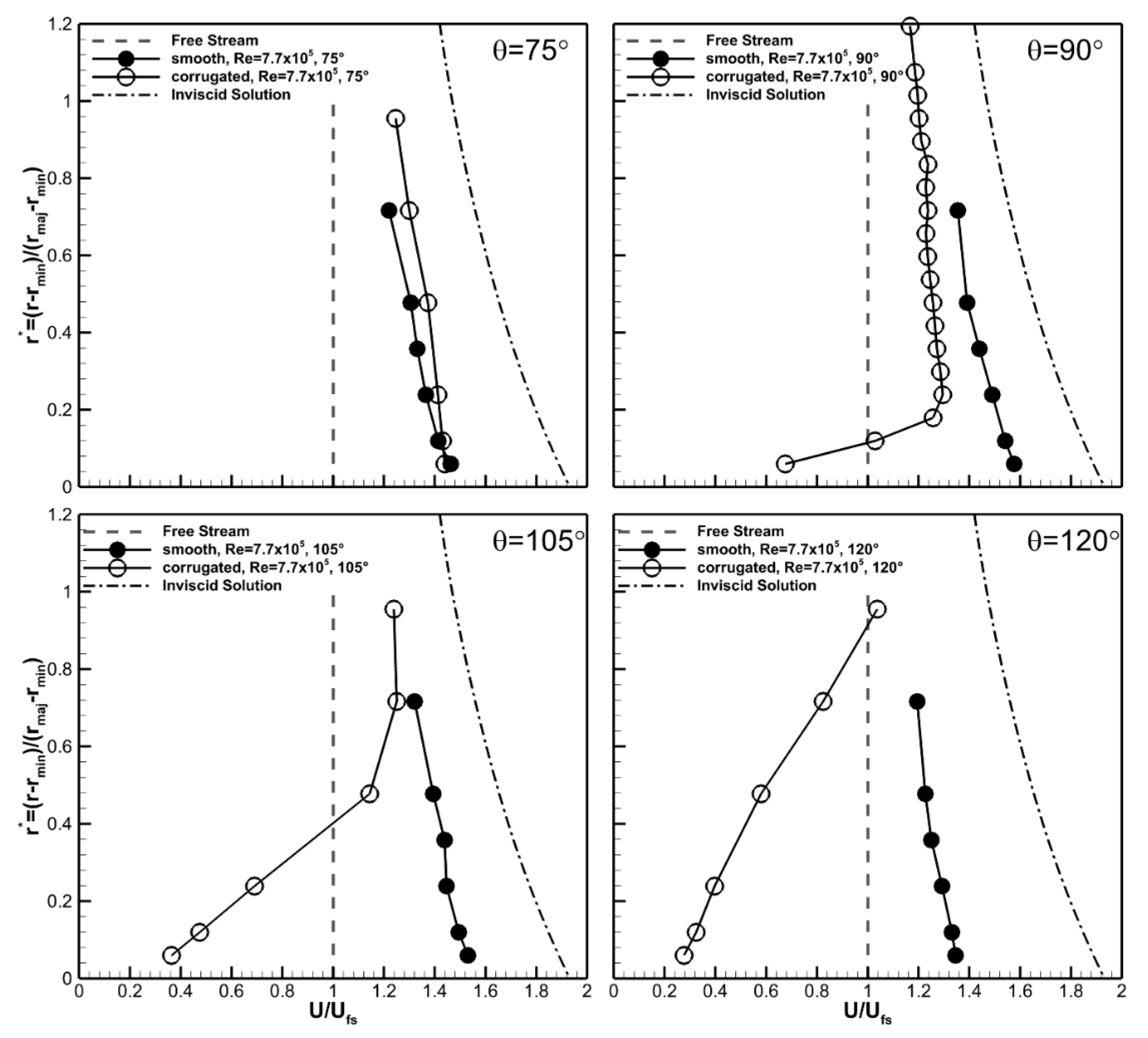
Velocity profiles at select angles are shown in Figure 15 to quantify the differences between the velocity fields for the two cases. The radial distance was rescaled in Figure 15 so that the model surface occurred at r* = 0, and the distance was normalized by the difference in height between the major and minor axis of the corrugated cylinder. This scaling method resulted in r* = 1 corresponding to the edge of the major diameter in the corrugated model and the equivalent dimensional distance for the smooth cylinder. The inviscid velocity profile at θ = 90° (dash-dot) and free stream speed (dashed) are also plotted for reference in Figure 15.
The velocity profiles were found to be qualitatively similar for the two geometries at θ = 75°. At this angular location the velocities were higher than the freestream at all radial measurement locations, with the highest value of Vθ/Vfs ≈ 1.43 at the measurement location closest to the surface. The velocity decreased to Vθ/Vfs ≈ 1.2 at the upper measurement location and appeared to be asymptotically approaching the freestream value. The boundary layer at the cylinder surface was relatively thin with a thickness less than the distance from the wall to the first measurement point at r* = 0.06.
At 90° the velocity profiles were qualitatively different for the two geometries. The flow around the smooth cylinder continued to accelerate due to the curvature of the wall. Velocities were higher at all radial locations compared to the 75° location for this geometry, and the boundary layer remained comparatively thin. The maximum value of the angular velocity was Vθ/Vfs ≈ 1.6, which was approximately 20% lower than the inviscid velocity of Vθ/Vfs ≈ 2.0. The corrugated cylinder showed a qualitatively different profile at this angular location. The changes in the structure of the velocity profile were most pronounced near the wall. The location of the peak velocity moved away from the wall forming what appeared to be a thick viscous boundary layer that occupied approximately 20% of the channel height. This resulted in a noticeably less uniform velocity profile, particularly near the wall. Additionally, the flow speed was lower than the freestream for approximately the bottom (i.e., near wall) 10% of the channel height. The flow speeds were comparatively lower at all locations than were measured at θ = 75° indicating the flow was decelerating within the channel.
These trends in the velocity data continued at θ = 105°. Here the velocity profile for the smooth cylinder was nominally the same as it was at θ = 90°, though the velocity magnitudes were slightly reduced. Comparison showed a slight deceleration in the velocity for the entire profile; however, this was expected due to the change in curvature of the model. The viscous boundary layer remained thinner than the data spacing. The low speed region of the corrugated cylinder continued to expand out away from the valley wall filling the bottom 60% of the channel height. Flow speeds lower than the free stream were measured in the bottom 40% of the channel height. By 120° the velocity magnitude was below the free stream in 80% of the corrugated channel height. The velocities also continued to decrease for the smooth cylinder, though they were still above the freestream value at all measurement locations. The velocity data were suggestive that viscous effects, likely due to the increased surface area of the corrugated cylinder, were responsible for the differences in the velocity and pressure results observed for that model.
Recall that the purpose of placing wind turbine blades next to a surface is to increase the kinetic energy of the wind before it enters the wind turbines blades. Ideally, one would prefer the flow speeds to be as high as possible (to maximize energy harvest) and uniform across the blades (for structural reasons). The experimentally measured and the computed inviscid velocity profiles were used to provide an estimate of the kinetic energy flux per unit width by:
K E = 0 1 V θ 3 ( r ) U F S 3 d r
It is acknowledged that the flow field varies in two dimensions (i.e., in the r-z plane) at a particular θ location for the two experimental geometries and that the actual kinetic energy flux over an area would differ from the integrated values using Equation (3). However, the estimate from this 1D integration provided a quantitative comparison of the geometries with the current data.
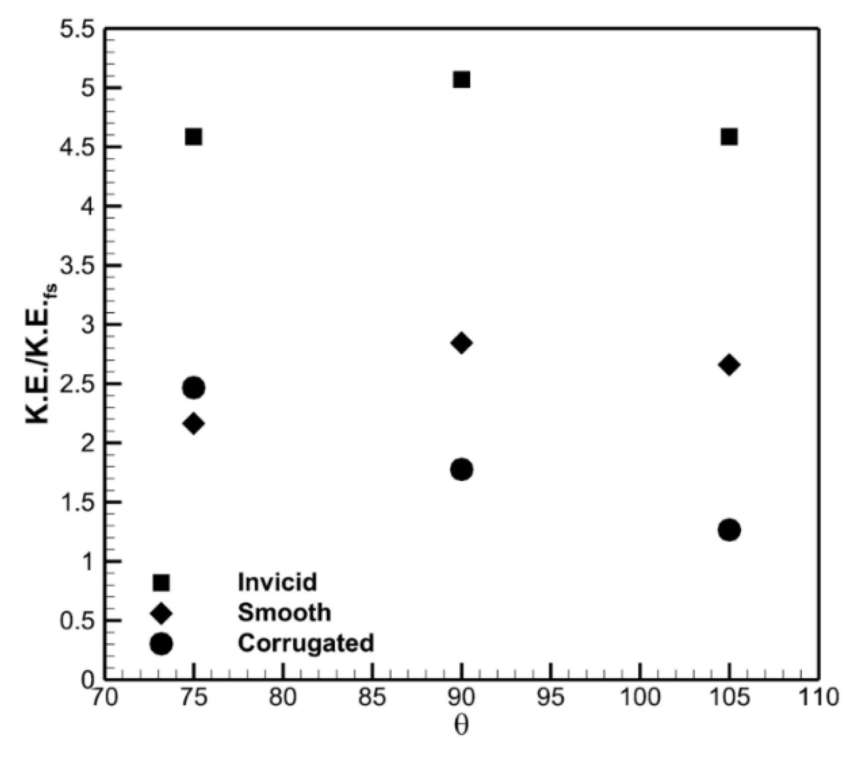
The inviscid profile provides a maximum of 5 times the kinetic energy in the free stream at θ = 90°, as shown in Figure 16. This is less than the “8 times” value because the inviscid velocity distribution varies with r as previously discussed. The smooth cylinder also showed a peak normalized kinetic energy at θ = 90°, though it was lower than for the inviscid flow (2.8 vs. 5). This result highlights the importance of the cubic functionality of the power with velocity. The corrugated cylinder had a maximum normalized kinetic energy at θ = 75° and was comparable in magnitude (~2.5) to the smooth cylinder at this location. The normalized kinetic energy decreased for the corrugated cylinder at θ = 90° and was lower than for the smooth cylinder case (1.7 vs. 2.8) and less than half of the inviscid case.
It is instructive to note that while both model cases were significantly below the inviscid kinetic energy potential, they were both above that for a rotor alone in a free stream (i.e., a value of 1). This indicated that the rotors could potentially experience enhancement due to placement next to both models. Interpretation of the values for the corrugated cylinder should be done carefully as the channel pressure and velocity data were suggestive that the velocities near the bounding walls would be lower than in the centerline of the channel. One should therefore expect that the kinetic energy flux (i.e., the area integrated KE flux) in the corrugated cylinder would be lower than what was calculated using Equation (3).
The turbine blades for the real-world application are best placed at θ = 90° for operational reasons. These reasons include the ability to self-align with the changes in the wind direction due to forces on the symmetrically placed pairs of rotor blades and the need for the system to be aligned out of the wind if needed. This azimuthal position therefore deserves additional discussion. Comparison of the data at θ = 90° clearly shows that the smooth cylinder had both higher velocities and a more uniform velocity profile. Uniformity in the velocity profile is desirable for blade loading and structural reasons in an accelerated application. In particular, the variation in the velocity profile measured for the corrugated model near the wall, approximately 50%, represents a potential difficulty if used as the loading near the tip varies significantly. The smooth cylinder on the other hand experiences a smaller fractional change, approximately 12%, across the blades. The lower velocities for the corrugated cylinder resulted in a 38% drop in the kinetic energy potential for the corrugated cylinder at this angular location. The results clearly showed that the smooth cylinder was a more desirable platform shape for the larger project.
4. Discussion

The pressure and velocity fields around short aspect ratio (AR = 0.93) smooth and corrugated cylinders were investigated experimentally using surface pressure and single-wire hot-wire anemometry. The corrugated cylinder was originally conceived as a strategy to accelerate and direct the wind into wind turbine blades to provide a scalable midrange “accelerated wind” system, which motivated this study. The smooth cylinder provided a canonical reference geometry for comparative purposes as well as a second candidate platform design. The smooth cylinder results are unique in that they were conducted for a smaller aspect ratio than is typically studied and for a non-surface mounted finite aspect ratio model. The goals of these experiments were to quantify and compare the surface pressures and flow fields around the low aspect ratio (AR = 0.93) smooth and corrugated cylinders. The experiments were performed without wind turbine blades, which represents the upper limiting condition for the motivating accelerated wind application. This then provides a “best case” scenario by which the designs could be compared.
The results indicated that the minimum pressure coefficient, Cp,min, was higher and the flow separated earlier for the smooth finite aspect ratio cylinder when compared to published results for a bounded (i.e., “infinite aspect ratio”) cylinder at similar Reynolds numbers. These results showed that the end effects on the finite aspect ratio cylinder played a significant role even at the center of the small aspect ratio cylinder and were consistent with prior work [18,25], which was conducted near the Re of the current work. These results then indicate that end effects are of critical importance when using low aspect ratio cylindrical bodies to accelerate the flow for wind turbine applications.
The corrugated cylinder showed smaller decreases in the pressure coefficient, Cp, and earlier separation compared to the smooth cylinder with the same aspect ratio. This occurred over the entire Reynolds number range investigated. Both of these results indicated that flow acceleration around the corrugated cylinder was lower than for the smooth cylinder. The early separation also resulted in an increased the size of the downstream wake and subsequently an increase in the drag coefficient for the corrugated cylinder. The azimuthal velocity measurements, Vθ, confirmed that the flow speeds around the corrugated cylinder were reduced when compared to the smooth cylinder. The velocity profiles revealed that the cause of the differences between the models was the development of a large viscous region in the channels due to the presence of the corrugation walls. There was a measurable variation in the pressure fields between end and internal channels for the corrugated cylinder indicating that end effects were also important for this geometry. Interestingly, the edge channels appeared to perform better (based on magnitude and location of Cp,min) than the center channel did. The end effects were mitigated by placing bounding plates on the upper and lower surfaces of the model, reducing channel to channel variation.
Both the smooth and corrugated cylinder models had azimuthal velocities that were below those for inviscid flow around a cylinder as expected given the viscous nature of real flows. However, both cases did show increased flow speeds compared to the free stream in the intended rotor plane. This resulted in a best case of 58% kinetic energy harvesting capability for the smooth cylinder case and 34% for the corrugated cylinder when compared to the idealized upper limit based on the inviscid flow case. This result provides useful insight for other accelerated wind applications, e.g., building augmented wind turbines, where turbines are located near structures that were not specifically designed to provide flow acceleration. In these cases, the results of this work show that shapes that may be suboptimal from an aerodynamic standpoint may still result in accelerated flow (compared to the free stream wind speed), which could be utilized for energy harvesting.
The following conclusions for the specific “accelerated wind” goal of this project were made based on these results. End effects must be considered in platforms designed for accelerated wind applications as they influence the velocity and pressure distributions in a negative manner. These can be mitigated when designing the shape of the end of the platforms. The earlier separation and larger wake region experienced by the corrugated model was consequential for design of a real world platform as it resulted in higher drag. This would require higher structural requirements if the corrugated model were to be chosen. Consider next the velocity entering the location of the wind turbine blade placement (θ = 90°). Kinetic energy considerations aside, a uniform velocity profile is desirable from a turbine blade structural standpoint. The azimuthal velocity profile in the planned rotor plane was significantly more uniform when compared to that measured for the corrugated cylinder indicating again that the smooth cylinder was a more favorable model moving forward.
The smooth cylinder was found to outperform the corrugated cylinder based on all of the study test metrics: magnitude and location of Cp,min, magnitude and uniformity of Vθ in the intended rotor plane, and the line integrated kinetic energy. From this it was concluded that the smooth cylinder clearly had higher potential for application in designed accelerated wind applications. The results of this work directly impacted the higher level goals of the project. Specifically, the smooth cylinder model was selected, while the corrugated model was abandoned, in the continuing design process due to the measurably poor performance of the corrugated model in this study.

Author Contributions

The data presented in this paper were the work of M.P. and D.B. M.P. was the graduate student who was responsible for the data acquisition, processing and analysis detailed in this work. D.B. was the primary investigator of this work and graduate advisor for M.P. All authors have read and agreed to the published version of the manuscript.

Funding

This work was funded through the New York State Energy and Research Development Authority Grant# 10596.

Conflicts of Interest

The authors declare no conflict of interest. Optiwind Inc. provided the specifications for the corrugated cylinder used in this study. Optiwind had no role in the study design, performance of the research, analysis of the data or writing and publication of this work.

References

  1. Johnson, G.L. Wind Energy Systems; Prentice-Hall: Englewood Cliffs, NJ, USA, 1985. [Google Scholar]
  2. Cheng, J.H.; Hu, S.Y. Innovatory designs for ducted wind turbines. Renew. Energy 2008, 33, 1491–1498. [Google Scholar]
  3. Anzai, A.; Nemoto, Y.; Ushiyama, I. Wind tunnel analysis of concentrators for augmented wind turbines. Wind Eng. 2004, 28, 605–614. [Google Scholar] [CrossRef]
  4. Van Bussel, G.J.W. The science of making more torque from wind: Diffuser experiments and theory revisited. J. Phys. Conf. Ser. 2007, 75, 12010. [Google Scholar] [CrossRef]
  5. Ohya, Y.; Karasudani, T.; Sakurai, A.; Abe, K.I.; Inoue, M. Development of a shrouded wind turbine with a flanged diffuser. J. Wind Eng. Ind. Aerod. 2008, 96, 524–539. [Google Scholar] [CrossRef]
  6. Gilbert, B.L.; Foreman, K.M. Experimental Demonstration of a Diffuser-Augmented Wind Turbine Concept. J. Energy 1979, 3, 235–240. [Google Scholar] [CrossRef]
  7. Phillips, D.G.; Nash, T.A.; Oakey, A.; Flay, R.G.J.; Richards, P.J. Computational fluid dynamic and wind tunnel modelling of a Diffuser Augmented Wind Turbine. Wind Eng. 1999, 23, 7–13. [Google Scholar]
  8. Bagheri-Sadeghi, N.; Helenbrook, B.T.; Visser, K.D. Ducted wind turbine optimization and sensitivity to rotor position. Wind Energy Sci. 2018, 3, 221–229. [Google Scholar] [CrossRef] [Green Version]
  9. Kanya, B.; Visser, K.D. Experimental validation of a ducted wind turbine design strategy. Wind Energy Sci. 2018, 3, 919–928. [Google Scholar] [CrossRef] [Green Version]
  10. Venters, R.; Helenbrook, B.T.; Visser, K.D. Ducted Wind Turbine Optimization. J. Sol. Energy Eng. 2018, 140. [Google Scholar] [CrossRef]
  11. Bahadori, M. Wind Tower Augmentation of Wind Turbines. Wind Eng. 1984, 18, 144–151. [Google Scholar]
  12. Duffy, R.E.; Jaran, C.; Ungermann, C. Aerodynamic Characteristics of the TARP (Toroidal Accelerator Rotor Platform) Wind Energy Conversion System; Rensselaer Polytechnic Inst.: Troy, NY, USA, 1980. [Google Scholar]
  13. Duffy, R.E.; Liebowitz, B. Verification Analysis of the Performance of the Toroidal Accelerator Rotor Platform Wind Energy Conversion System; NYSERDA: Albany, NY, USA, 1988.
  14. Weisbrich, A.L.; Ostrow, S.L.; Padalino, J.P. WARP: A Modular Wind Power System for Distributed Electric Utility Application. IEEE Trans. Ind. Appl. 1996, 32, 778–787. [Google Scholar] [CrossRef]
  15. Bohl, D.; Helenbrook, B.; Kanya, B.; Visser, K.; Marvin, R.; Mascarenhas, B.; Parker, M.; Rocky, D. Analysis and Design of a Wind Turbine with a Wind Accelerator. In Proceedings of the 29th AIAA Applied Aerodynamics Conference, Honolulu, HA, USA, 27–30 June 2011. [Google Scholar]
  16. Ameri, A.A.; Rashidi, M. Analysis of a Concept for a Low Wind Speed Tolerant Axial Wind Turbine. In Proceedings of the ASME Turbo Expo: Turbine Technical Conference and Exposition, Vancouver, BC, Canada, 6–10 June 2011. [Google Scholar]
  17. Prandtl, L.; Tiejens, O.G. Fundamentals of Hydro- and Aeromechanics; Dover Publications: New York, NY, USA, 1934. [Google Scholar]
  18. Achenbach, E. Distribution of local pressure and skin friction around a circular cylinder in cross-flow up to Re = 5 × 10⁶. J. Fluid Mech. 1968, 34, 625–639. [Google Scholar] [CrossRef]
  19. Achenbach, E. Influence of surface roughness on the cross-flow around a circular cylinder. J. Fluid Mech. 1971, 46, 321–335. [Google Scholar] [CrossRef]
  20. Roshko, A. On the Drag and Shedding Frequency of Two-Dimensional Bluff Bodies; National Adivsory Committee for Aeronautics: Washington, DC, USA, 1954.
  21. Buranall, W.; Loftin, L. Experimental Investigation of the Pressure Distribution about a Yawed Circular Cylinder in the Critical Reynolds Number Range; National Advisory Committee for Aeronautics, Ed.; National Advisory Committee for Aeronautics: Washington, WA, USA, 1951.
  22. Park, C.W.; Lee, S.J. Flow structure around a finite circular cylinder embedded in various atmospheric boundary layers. Fluid Dyn. Res. 2002, 30, 197–215. [Google Scholar] [CrossRef]
  23. Park, C.W.; Lee, S.J. Free end effects on the near wake flow structure behind a finite circular cylinder. J. Wind Eng. Ind. Aerod. 2000, 88, 231–246. [Google Scholar] [CrossRef]
  24. Uematsu, Y.; Yamada, M.; Ishii, K. Some Effects of Free-Stream Turbulence on the Flow Past a Cantilevered Circular-Cylinder. J. Wind Eng. Ind. Aerod. 1990, 33, 43–52. [Google Scholar] [CrossRef]
  25. Zdravkovich, M.M.; Brand, V.P.; Mathew, G.; Weston, A. Flow Past Short Circular-Cylinders with 2 Free Ends. J. Fluid Mech. 1989, 203, 557–575. [Google Scholar] [CrossRef]
Figure 1. Conceptual views of (a) original Optiwind 150 kW wind turbine design. (b) Conceptual smooth cylinder design. Rotors shown schematically by dotted circles. In application, direction of wind would be into the page so that turbine blades are at ±90° with respect to the wind direction.
Fluids 05 00025 g001
Figure 2. Schematic of corrugated cylinder model. All dimensions are in meters.
Fluids 05 00025 g002
Figure 3. Schematic of side wall pressure taps.
Fluids 05 00025 g003
Figure 4. Experimental set-up for the (a) corrugated and (b) smooth models.
Fluids 05 00025 g004
Figure 5. Surface velocity and pressure distribution for inviscid flow around a circular cylinder.
Fluids 05 00025 g005
Figure 6. Pressure distribution around cylinder as a function of Reynolds number. Data from Achenbach [18].
Fluids 05 00025 g006
Figure 7. Surface pressure distribution for the smooth cylinder case.
Fluids 05 00025 g007
Figure 8. Pressure distributions through the corrugated cylinder center channel valley.
Fluids 05 00025 g008
Figure 9. Comparison of the surface pressure distribution around the corrugated and smooth cylinders. (a) Re = 1.9 × 10⁵, (b) Re = 7.7 × 10⁵.
Fluids 05 00025 g009
Figure 10. (a) θmin and (b) Cp,min versus Reynolds number for the smooth and corrugated cylinders.
Fluids 05 00025 g010
Figure 11. Pressure distributions at (a) ϕ = 42° and (b) ϕ = 98° up the channel wall.
Fluids 05 00025 g011
Figure 12. Pressure distribution as a function of channel wall location.
Fluids 05 00025 g012
Figure 13. Comparison of pressure distribution in the center and top channels. (a) Re = 1.9 × 10⁵, (b) Re = 7.7 × 10⁵.
Fluids 05 00025 g013
Figure 14. Velocity distribution around the (a) smooth and (b) and corrugated cylinders. Note: Solid black denotes minor diameter of the corrugated cylinder and the diameter of the smooth cylinder. The dashed line in (b) represents the location of the major diameter. The dash-dot-dash line shows the contour of u/Vfs = 1. Re = 7.7 × 10⁵. Flow left to right.
Fluids 05 00025 g014
Figure 15. Vθ velocity profiles normal to the surface. Angular position as indicated. Re = 7.7 × 10⁵.
Fluids 05 00025 g015
Figure 16. Normalized kinetic energy from measured velocity profiles. Re = 7.7 × 10⁵.
Fluids 05 00025 g016