Article

Low-Temperature Synthesis Approach for Calcium Hydroxyapatite Coatings on Titanium Substrate

1
Department of Inorganic Chemistry, Vilnius University, Naugarduko 24, LT-03225 Vilnius, Lithuania
2
Center for Physical Sciences and Technology, Sauletekio 3, LT-10257 Vilnius, Lithuania
*
Author to whom correspondence should be addressed.
Inorganics 2023, 11(1), 33; https://doi.org/10.3390/inorganics11010033
Submission received: 15 December 2022 / Revised: 29 December 2022 / Accepted: 3 January 2023 / Published: 7 January 2023
(This article belongs to the Special Issue Inorganics: 10th Anniversary)

Abstract

:
In this study, a low-temperature synthetic approach was developed for the fabrication of calcium hydroxyapatite (CHAp) coatings on a titanium substrate. The titanium substrates were first coated with CaCO3 by a spin-coating technique using a sol–gel chemistry approach, and the obtained product was transformed into CHAp during a dissolution–precipitation reaction. The phase purity and structural and morphological features of the obtained CHAp coatings were evaluated by X-ray diffraction (XRD) analysis, FTIR spectroscopy, Raman spectroscopy, scanning electron microscopy (SEM) and using a 3D optical profilometer. It was demonstrated that almost-single-phase CHAp formed on the titanium substrate with a negligible number of side phases, such as Na2HPO4 (starting material) and TiO2. In the Raman spectrum of the CHAp coating, the peaks of phosphate group vibrations were clearly seen. Thus, the obtained results of Raman spectroscopy correlated well with the results of X-ray diffraction analysis. The corrosive behaviour of CHAp coatings on a titanium substrate was also evaluated using electrochemical methods. It was found that the corrosion resistance of titanium coated with CHAp increased significantly. These CHAp thin films may be potential candidates for use in not only in regenerative medicine but also in the development of different sensors.

1. Introduction

Calcium hydroxyapatite (Ca10(PO4)6(OH)2; CHAp) is one of the substances found in bone tissue, being involved in bone growth and characterized by excellent biocompatibility. CHAp shows strong osteopermeable properties, making it a particularly attractive material for biomedical applications [1]. A high surface area, reactivity and biomimetic morphology make nano-CHAp more favourable in applications such as orthopaedic implant coating or bone substitute filler [2]. Recent efforts have been focused on the possibility of combining nano-CHAp with other drugs and materials for multipurpose applications, such as antimicrobial treatment, osteoporosis treatment, sensing and magnetic manipulation [3]. To build more effective nano-CHAp and composite systems, the synthesis processes, chemistry and toxicity have to be thoroughly investigated. These nanomaterials have a significant role in many biomedical areas, such as sustained drug and gene delivery, bioimaging, magnetic resonance, cell separation and hyperthermia treatment, due to their promising biocompatibility [4].
The use of artificial biomaterials has been gaining therapeutic scope in diverse clinical applications. However, an equally attractive field of application involving CHAp is its use in various sensors. The CO-gas-sensing property of CHAp ceramics with an average crystallite size of 31–54 nm was investigated by Mahabole et al. [5]. It was concluded that CHAp can be used as a CO gas sensor at an optimum temperature near 125 °C. The results presented in the study [6] indicate that the CHAp sensor is applicable for qualitative and conformational analysis of protein adsorption. CHAp was also used to develop a potentiometric sensor for phosphate ions [7]. Alkaline phosphatase (ALP) is a critical biological marker for osteoblast activity during early osteoblast differentiation. The highly sensitive and rapidly responsive novel near-infrared fluorescent probes for the fluorescent detection of ALP were described [8]. ALP detection in vivo was achieved using NIR probe-labelled three-dimensional calcium-deficient hydroxyapatite (CDHA) scaffolds. The results suggest the possibility of early-stage ALP detection during neo-bone formation inside a bone defect, by in vivo fluorescent evaluation using 3D CDHA scaffolds. Recent trends in the application of calcium apatite compounds for electrochemical detection of heavy metals or H2O2 are shown in the studies [9,10].
Continuous research on CHAp nanomaterials (CHAp-NMs) has explored novel fabrication approaches coupled with functionalization and characterization methods [11,12]. CHAp coatings can be deposited using atomic layer deposition (ALD) technology [13] or magnetron sputtering [14]. Due to the quality of the produced coatings, these methods are the main technologies for the fabrication of thin layers in a vacuum. The electrochemical method of CHAp coating deposition is a popular way of forming coatings by electrolysis from an electrolyte with the appropriate composition. The method does not require the above-mentioned expensive equipment, and the thickness and structure of the deposited coatings can be controlled by varying the appropriate potential, current density, electrolyte composition and pH [15]. Using the aqueous sol–gel method, CHAp can be synthesized on various substrates (e.g., titanium, quartz, silicon) by controlling the temperature, pH and concentration [16]. This method is considered a high-temperature approach, requiring elevated temperatures to obtain the CHAp crystalline phase. However, high temperatures do not support the formation of nanocrystalline materials [17]. The CHAp coatings obtained at 1000 °C could be inhomogeneous, for example, consisting of two distinct regions: one with small grains, approximately 200 nm in size, and one with larger grains, approximately 800 nm in diameter [18]. Additionally, the formation of the TiO2 phase at high temperatures reduces adhesion of CHAp films on Ti substrates [19].
In this study, we investigated the possibility of fabricating CHAp thin films at a sufficiently low temperature, applying environmentally friendly sol–gel and dissolution–precipitation methods [1,20,21,22] for the first time using the spin-coating technique. The spin-coating method offers great promise for the fabrication of thin films with desirable properties [23]. The spin-coating technique allows very homogeneous samples composed of nano-scaled particles to be fabricated [16]. This low-temperature synthetic approach was developed for the fabrication of CHAp coatings on Ti substrates; however, it could be easily used for the formation of CHAp nanostructures on different substrates. The results of characterization of the obtained CHAp are presented herein.

2. Results

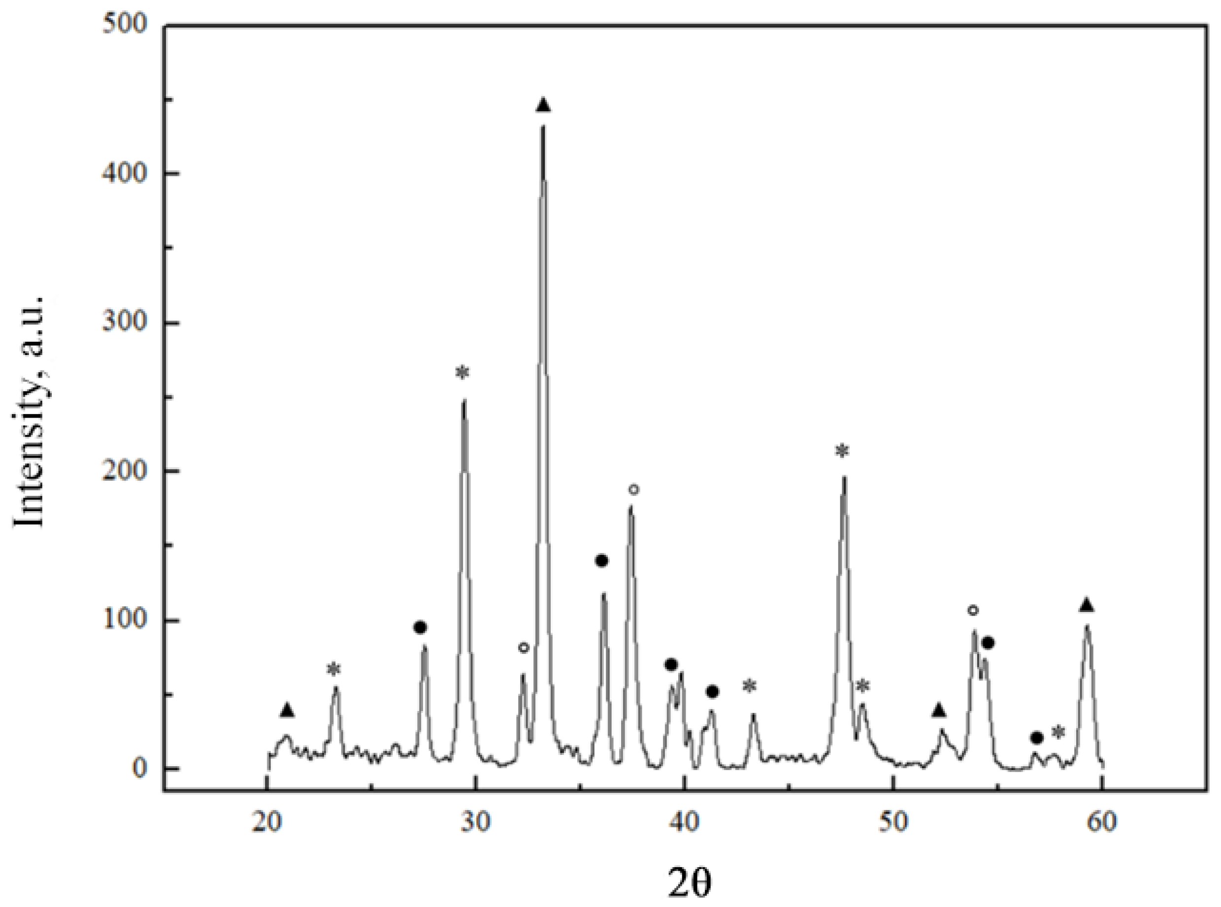
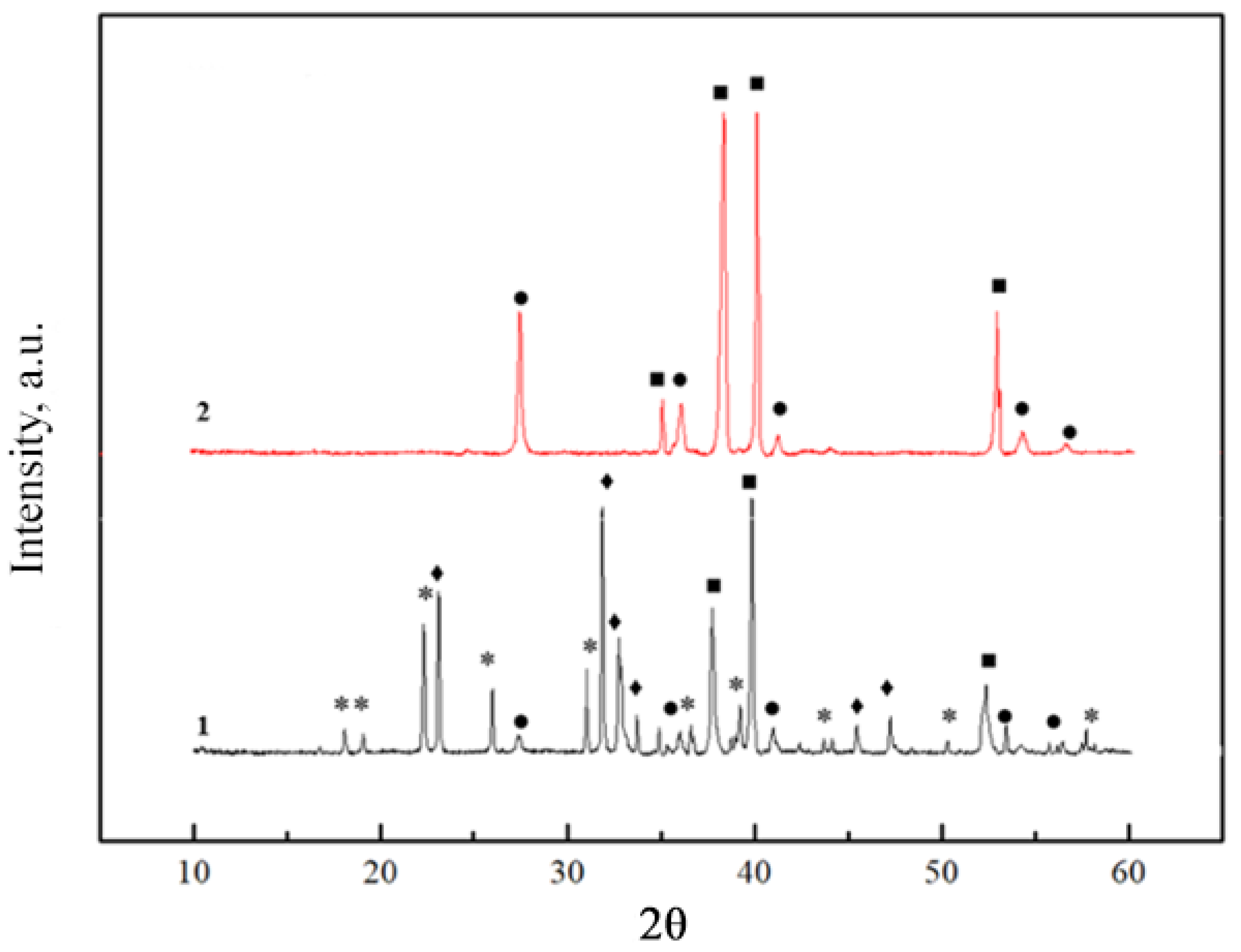
2.1. X-ray Diffraction Analysis

The phase composition of the obtained calcium carbonate coatings on the titanium substrate was determined by X-ray diffraction analysis (Figure 1).
According to the obtained results, the formation of CaCO3 after 20 coating procedures was evidently observed. Additionally, the XRD patterns contained intense diffraction peaks corresponding to TiO2 (rutile) CaO and CaTiO3 crystalline phases.
Figure 2 shows the XRD patterns of the resulting CaCO3 coating on the titanium substrate after 28 days of immersion in Na2HPO4 solution and the Ti substrate was annealed at 600 °C.
It can be seen that the CHAp coating was successfully formed. The diffraction peaks characteristic of the crystalline CHAp phase were observed [16,19]. Additionally, the peaks attributed to secondary phases such as Na2HPO4 (from immersion solution), Ti (substrate) and TiO2 were also detected. It could be concluded that CHAp formed, but it did not prevent the formation of TiO2. On the other hand, the characteristic peaks of CaTiO3 are not visible, which may have been due to the fact that the CaTiO3 layer was coated with CHAp. The influence of Ti substrate modification on the formation of CHAp coatings was previously deeply investigated [19]. To achieve a better quality of CHAp coatings, Ti substrates were modified by adding a calcium titanate sublayer or additional preheating at 650 °C. One of the key advantages of the sol–gel technique is its capacity to produce homogeneous materials [24]. It is evident from the XRD results that the combined sol–gel and dissolution–precipitation reactions method also produces homogeneous CHAp coatings.

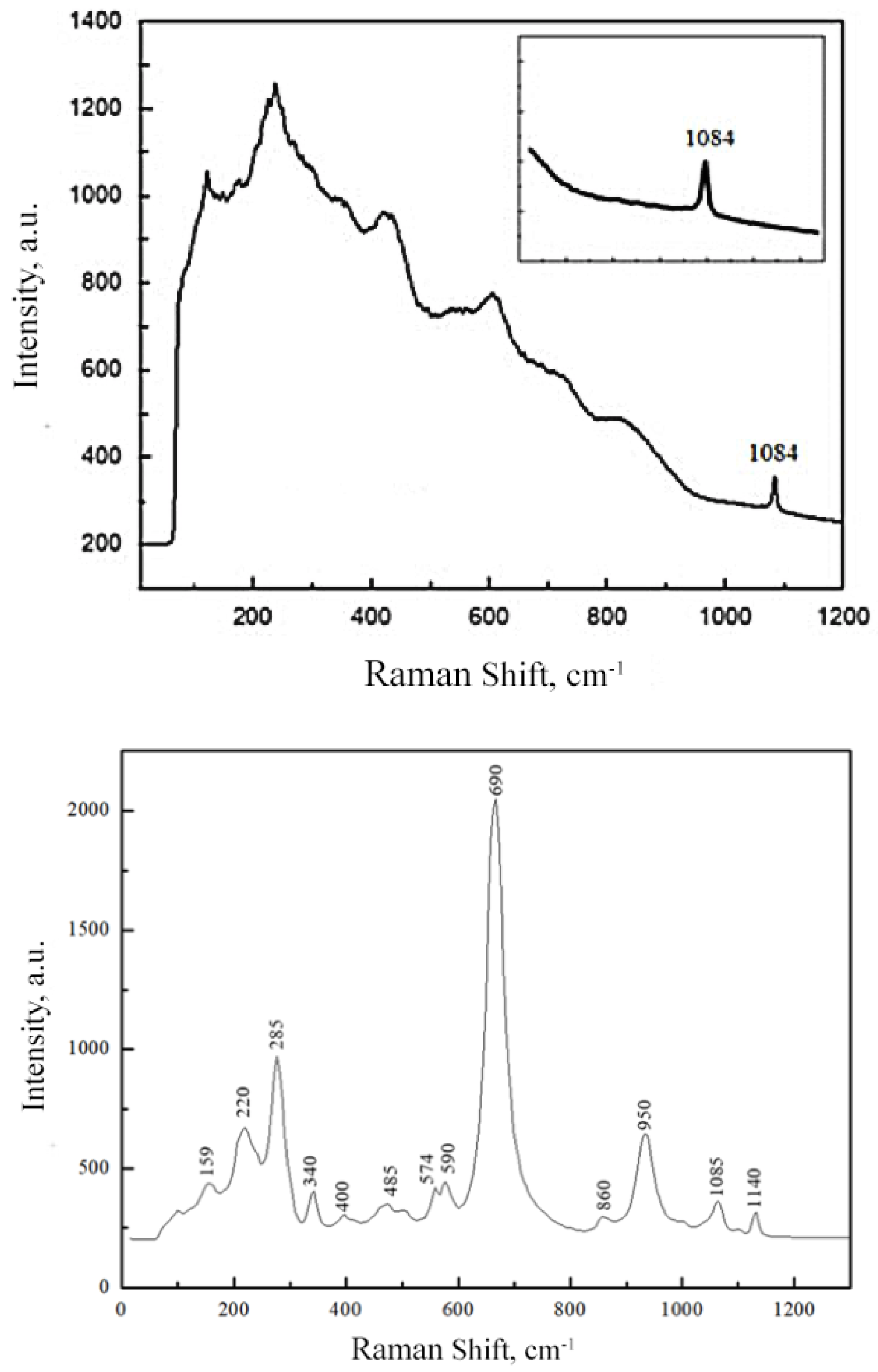
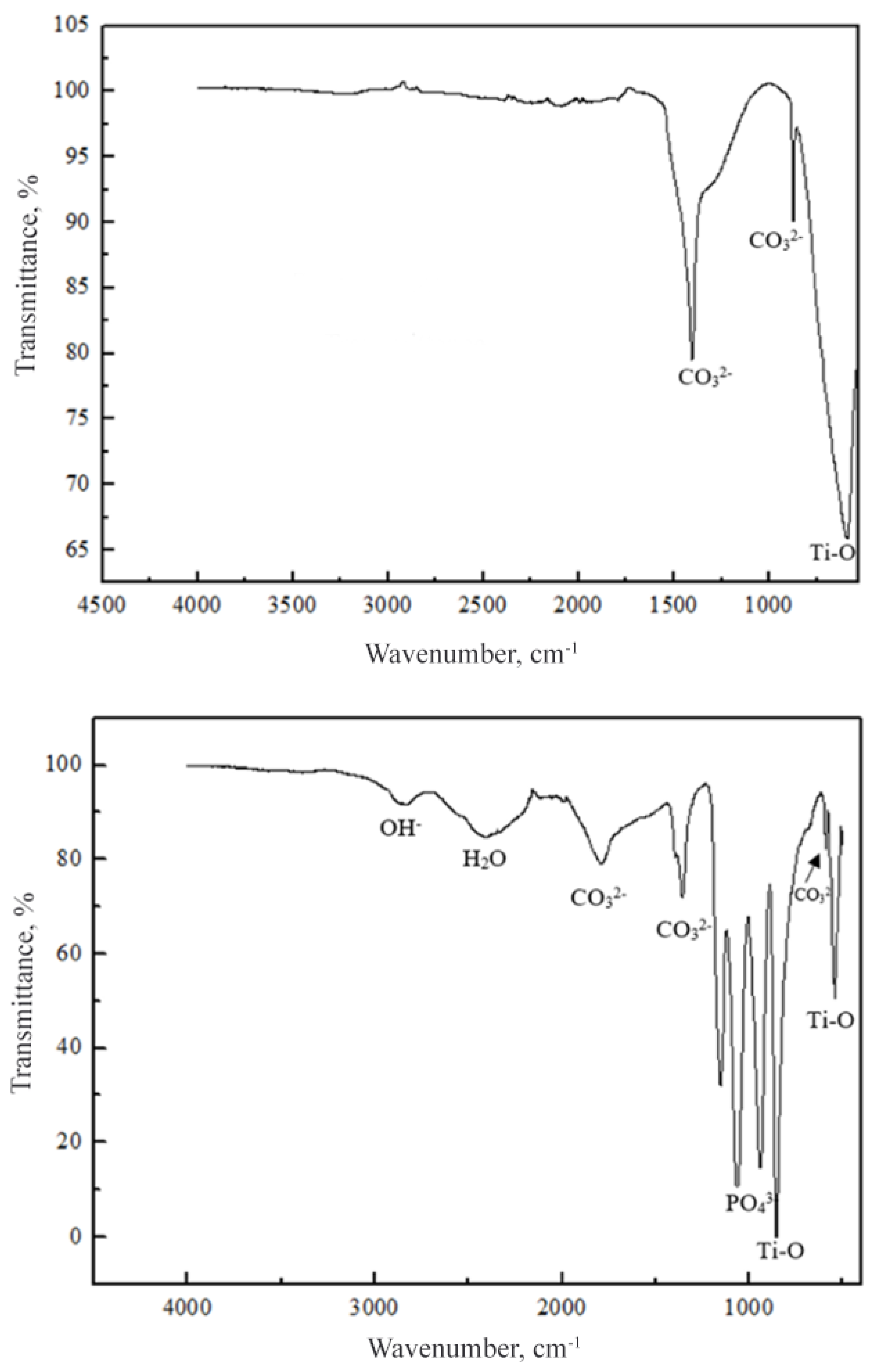
2.2. Raman and FTIR Spectroscopy

Raman spectra of the sol–gel-derived CaCO3 coating and CHAp coating obtained following the dissolution–precipitation reaction are shown in Figure 3.
A high background is visible in the Raman spectrum of the CaCO3 coating; however, the observed peak at 1084 cm−1 corresponds to the symmetric stretching of calcium carbonate [25]. In the Raman spectrum of the CHAp coating, the peaks of phosphate group vibrations at 400, 574, 590, 950 and 1085 cm−1 are seen [25]. The peak at about 280 cm−1 is attributed to the Ca-PO4 lattice. All this confirms that the CHAp coating was formed by the dissolution–precipitation process. The most intense peak observed, at 690 cm−1, is ascribed to the Ti substrate. In addition, the peaks at 159, 220 and 485 could be attributed to the TiO2 phase [26]. The obtained results of Raman spectroscopy correlate well with the results of X-ray diffraction analysis.
Figure 4 demonstrates the FTIR spectra of synthesized coatings. The absorption bands observed at 1411 cm−1 and 879 cm−1 in the spectrum of the CaCO3 coating can be assigned to the stretch vibrations of the carbonate ion [27,28]. The intense absorption band detected at ~590 cm−1 is attributed to the vibration of Ti-O in titania.
The results deduced from the FTIR spectrum of the formed CHAp coating are in good agreement with the results of XRD and Raman spectroscopy, confirming the formation of intermediate (CaCO3) and end products (Ca10(PO4)6(OH)2):
10   C a C O 3   +   6 N a 2 H P O 4   +   2   H 2 O   =   C a 10 ( P O 4 ) 6 ( O H ) 2   +   8   N a H C O 3   +   2   N a 2 C O 3
According to the origin of observed absorption bands, the formation of carbonated hydroxyapatite (Ca10−x(PO4)6−x(CO3)x(OH)2−x−2y(CO3)y) occured during the dissolution–precipitation reaction [28,29].

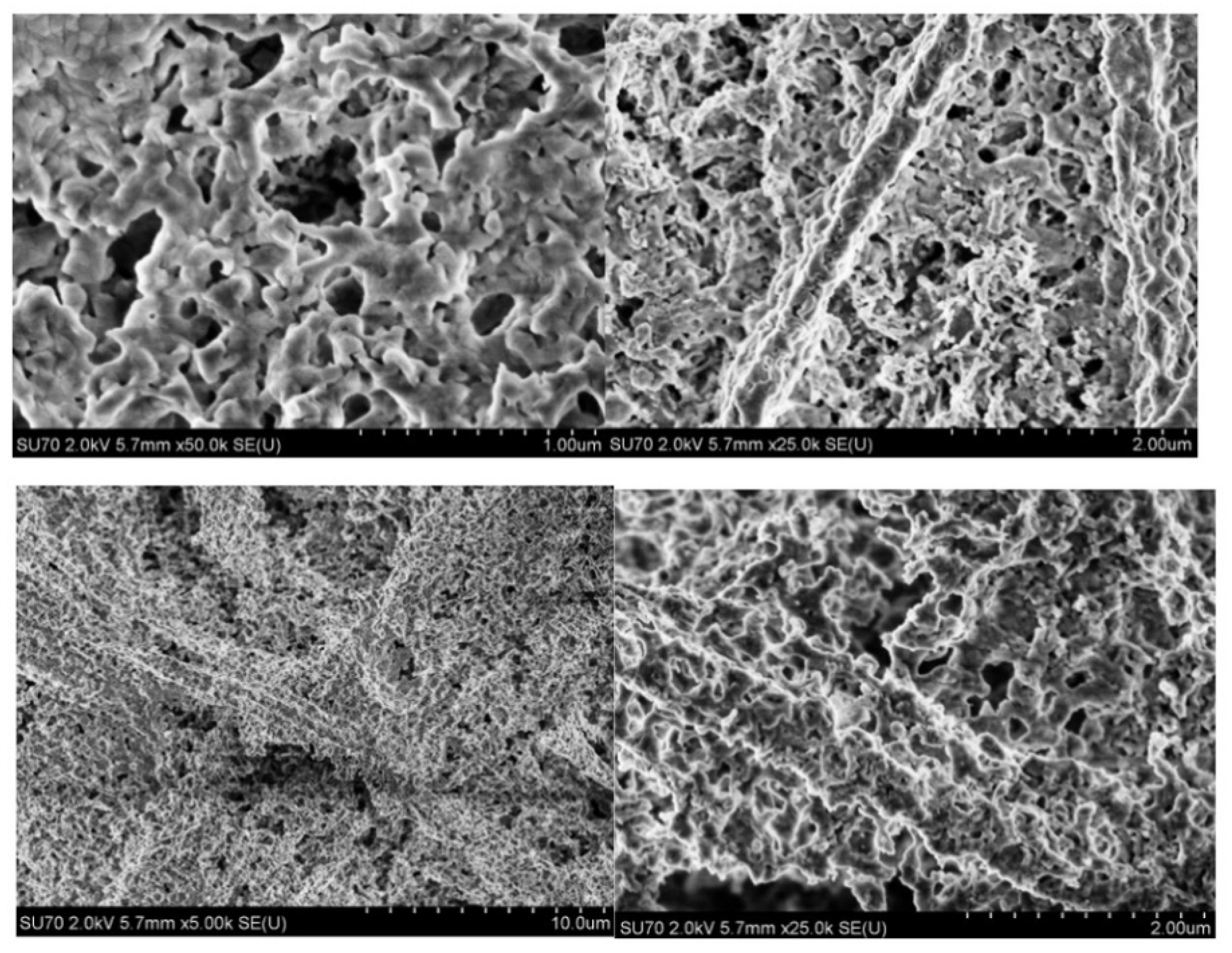
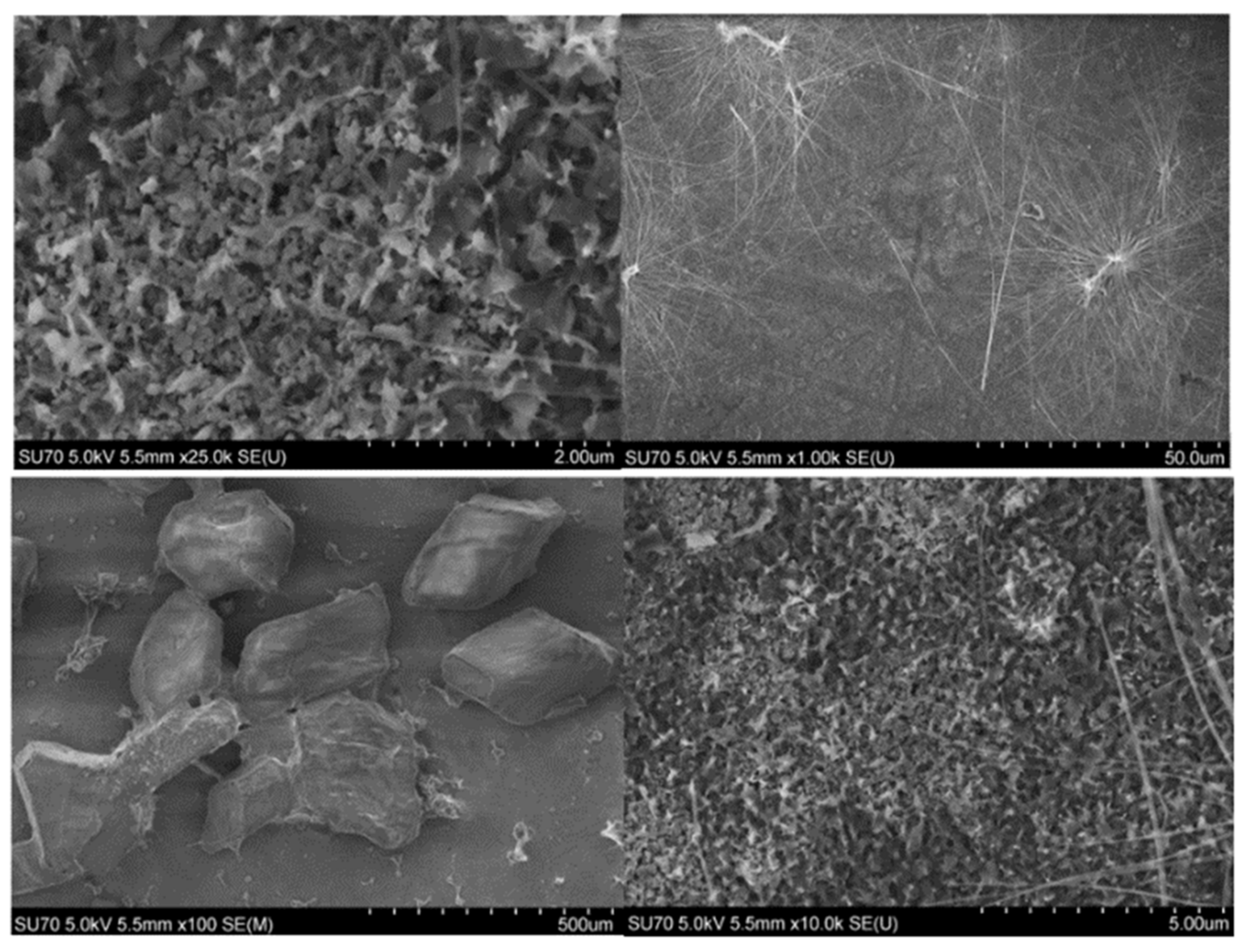
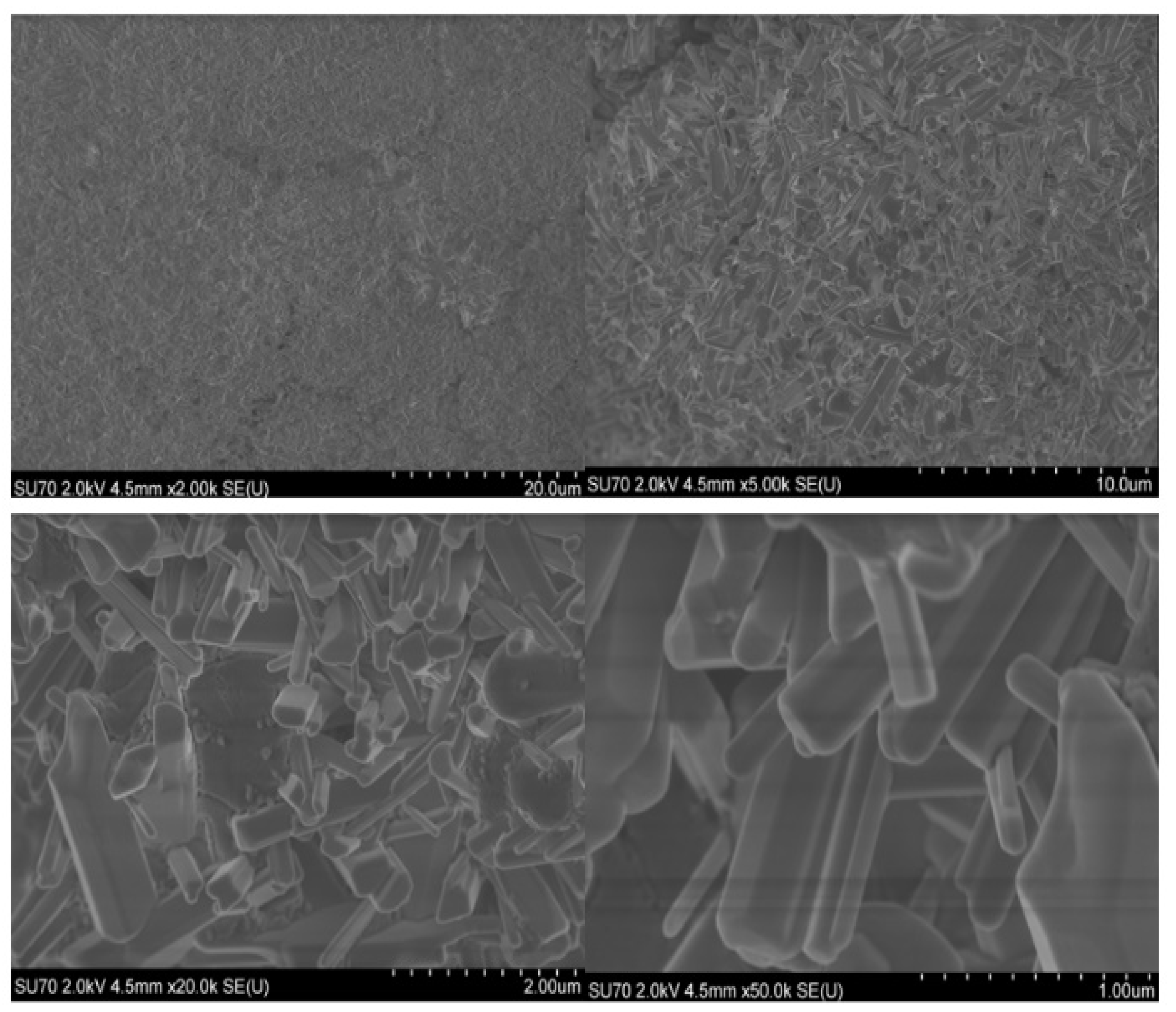
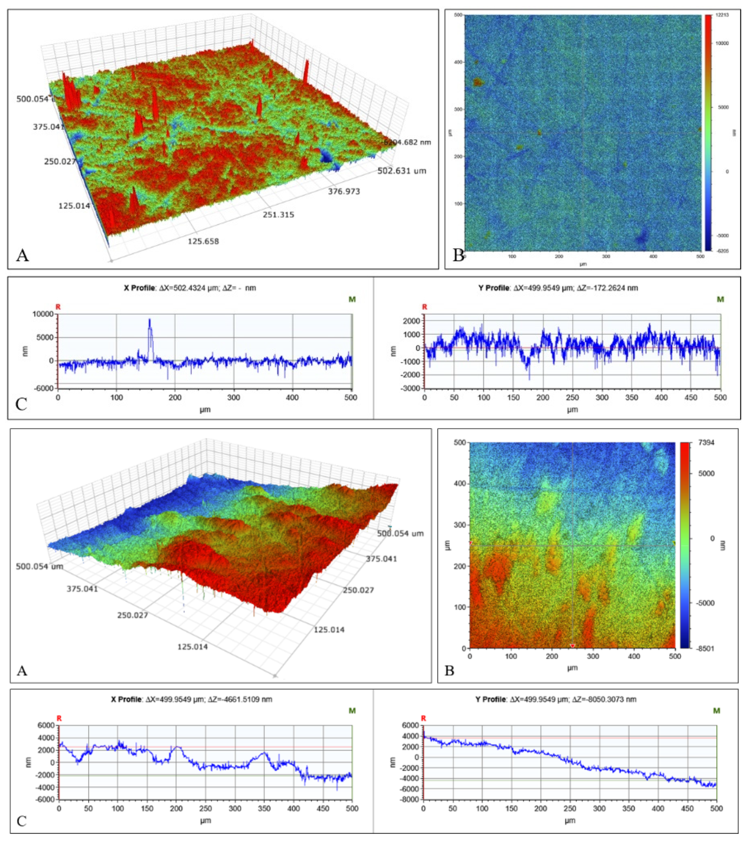
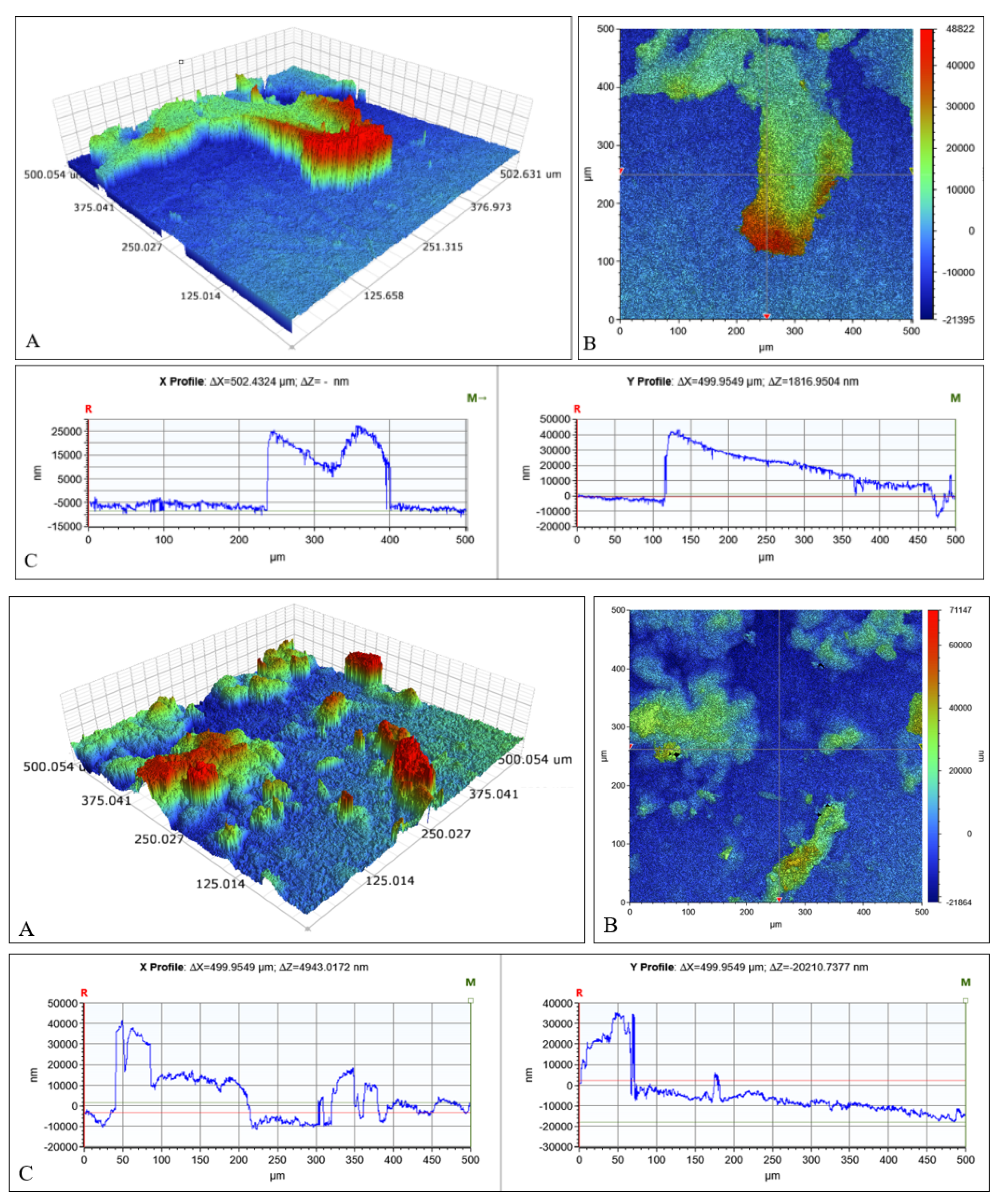
2.3. Microscopical Characterization

Figure 5 shows the SEM micrographs of the formed CaCO3 after spin-coating and thermal treatment procedures. The resulting porous surface was homogeneous with evenly distributed particles. The obtained SEM images confirm that CaCO3 layers were formed and the Ti substrate was uniformly covered.
SEM micrographs of CHAp coatings after immersion of the CaCO3 coating in Na2HPO4 solution are presented in Figure 6. It can be seen from the SEM micrographs obtained at lower magnification that dendritic clusters of CHAp and Na2HPO4 crystallites formed on the titanium surface. The surface of CHAp is rough and porous [30]. However, at higher magnification, the formation of homogenously distributed plate-like crystals and spherical particles is seen. After annealing the obtained CHAp coating at 900 °C, the morphology of the crystals changed dramatically, with the formation of rods of 1–2 µm in length and 100–150 nm in width (see Figure 7). This is in good agreement with literature data [1,16].
The surface morphology of CHAp films was also studied with an optical 3D profilometer (see Figure 8 and Figure 9). As seen from Figure 8, the surface roughness of the Ti substrate increased with the formation of the CaCO3 coating. The results presented in Figure 9 show that the formed CHAp coatings were not evenly distributed on the Ti substrate. Moreover, the surface roughness observed for CHAp coatings was higher than that seen for the CaCO3 coating. These results partially correlate with morphological features determined by SEM analysis. The surface roughness and average coating height were observed to increase slightly after annealing at 900 °C. The maximum roughness (7905 nm) and average height (10,296 nm) were determined for these coatings.

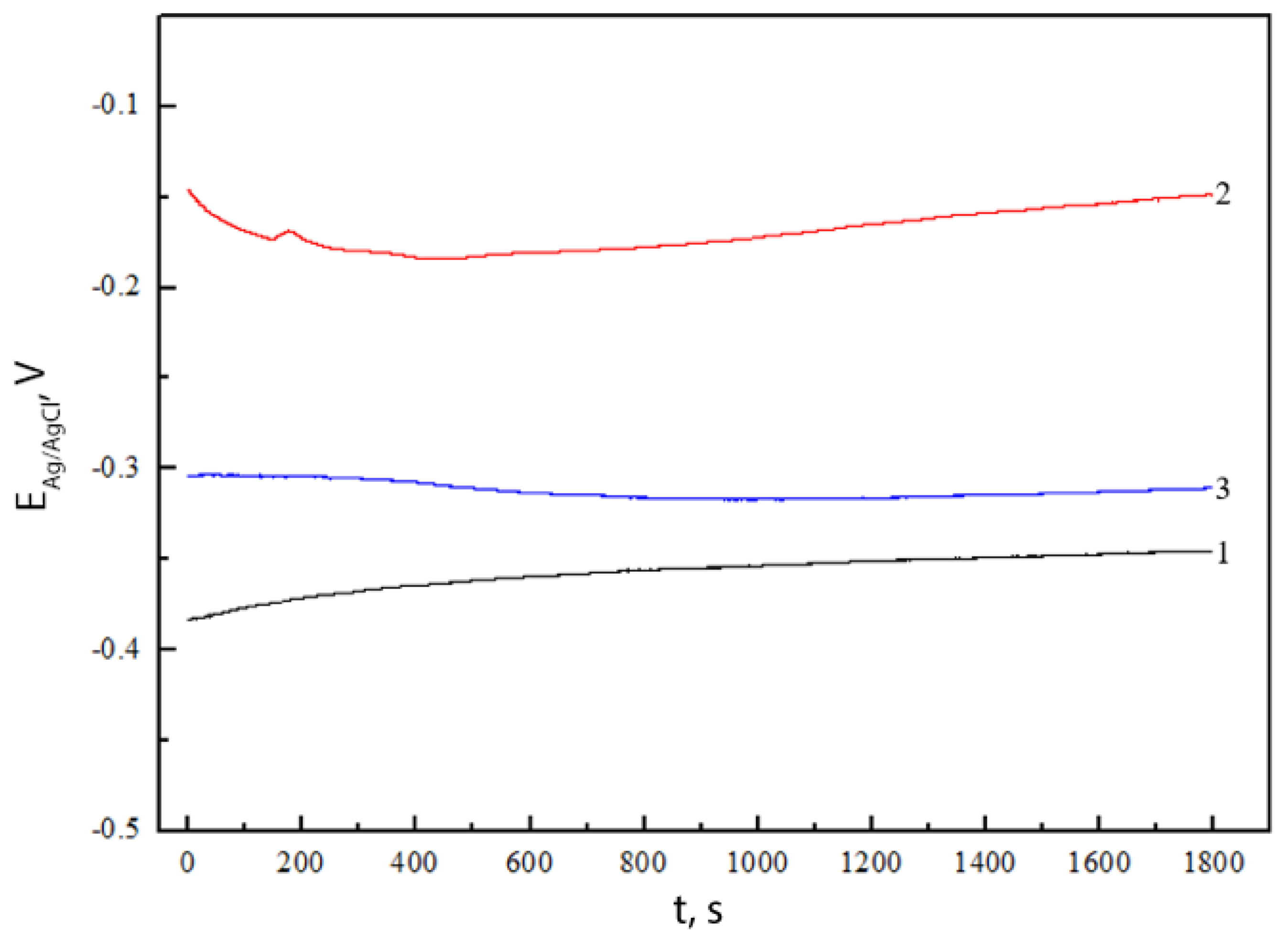
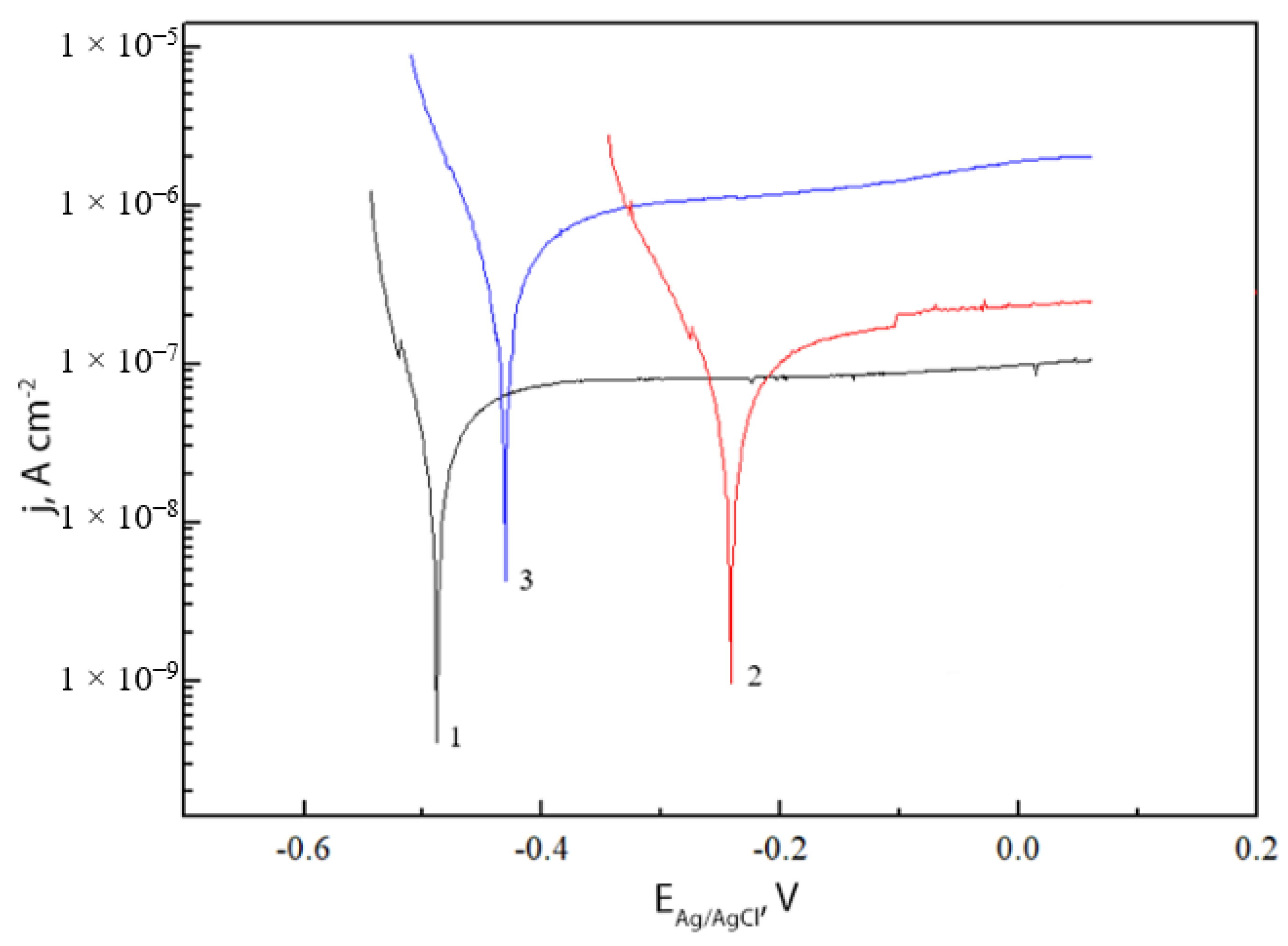
2.4. Electrochemical Characterization

In order to study the corrosion behaviour of fabricated coatings, first of all, the time dependences of the open-circuit potentials (Eocp) of the samples were measured in Hanks’ balanced salt solution (Figure 10).
The open-circuit potential is a parameter that describes the relative corrosion stability of the sample in the solution. The stability of Eocp shows that all the processes that determine its value are in a stationary state. The rates of spontaneous reactions have stabilized and the investigated electrode surface is stable. If Eocp shifts to more positive values, it indicates a decrease in the corrosivity of the electrode, i.e., blocking of the surface by a passive layer. If Eocp shifts to more negative potentials, it indicates that the investigated system is in the corrosion zone. As can be seen from Figure 10, the Eocp value of the CHAp coating initially decreased to ~−0.18 V, indicating that the corrosion activity increased, which is related to the formation of a protective layer of the formed CHAp coating. The Eocp of the working electrode began to shift to more positive values after 7 min and reached a quasi-stationary value. In this case, a new passivation layer was formed on the surface of the tested electrode. The Eocp of the annealed CHAp coating did not change much with increasing exposure time. It was observed that this coating reached a quasi-stationary value after ~6 min., and the passivation layer was formed quite quickly, which indicates the formation of stable coating. The Eocp of the Ti substrate started to become positive in the initial stage of immersion, and the time-invariant value of the Eocp settled after ~11 min. The difference in Eocp values between the tested samples was negligible, indicating that the surface properties of formed CHAp coatings were similar.
The influence of the formed CHAp coating on the corrosion rate of the titanium in Hanks’ balanced salt solution was evaluated using the Tafel dependences of the electrodes. The Tafel polarization curves were recorded when the Eocp of the electrodes reached quasi-stationary values (Figure 11).
The corrosion rates (jcorr) were determined by extrapolation from linear ranges of cathodic and anodic Tafel dependencies. The determined corrosion rates are presented in Table 1.
The polarization curves of the CHAp coating shifted towards more positive values, indicating a less active corrosion process. Table 1 also presents the tendencies of the cathodic (bc) and anodic (ba) Tafel dependencies of the tested samples. It can be seen that the CHAp coating was characterized by higher bc values than the uncoated Ti substrate. The anodic tendency of the Tafel dependence of the obtained coatings decreased compared to that of the titanium substrate. The largest positive boost was determined for the as-prepared CHAp coating. Interestingly, the Eocp of the post-annealed CHAp coating was lower. This may have been influenced by the porosity of the coating, which did not prevent the Hanks’ balanced salt solution from contacting the metal and causing corrosion.
Evidently, these newly fabricated porous and sufficiently rough CHAp films can be successfuly used not only as biomimetic nanotherapeutic coatings but also as electochemical sensors [31], thermoluminescent sensors [32], or pH-sensitive fluorescent protein sensors [33]. The CHAp could be easily doped with lanthanide ions [34]. These nanostructures could be applied for the development of novel pH-responsive systems, which can determine the acidity of biofilms fluorometrically [35]. Finally, it is well known that pH is a critical indicator of bone physiological function and disease status. The suggested CHAp coatings fabricated at low temperatures could be applied for the development of non-invasive and real-time sensing of bone pH in vivo [36]. Therefore, the application of our CHAp system as a bone pH sensor currently is under investigation.

3. Experimental

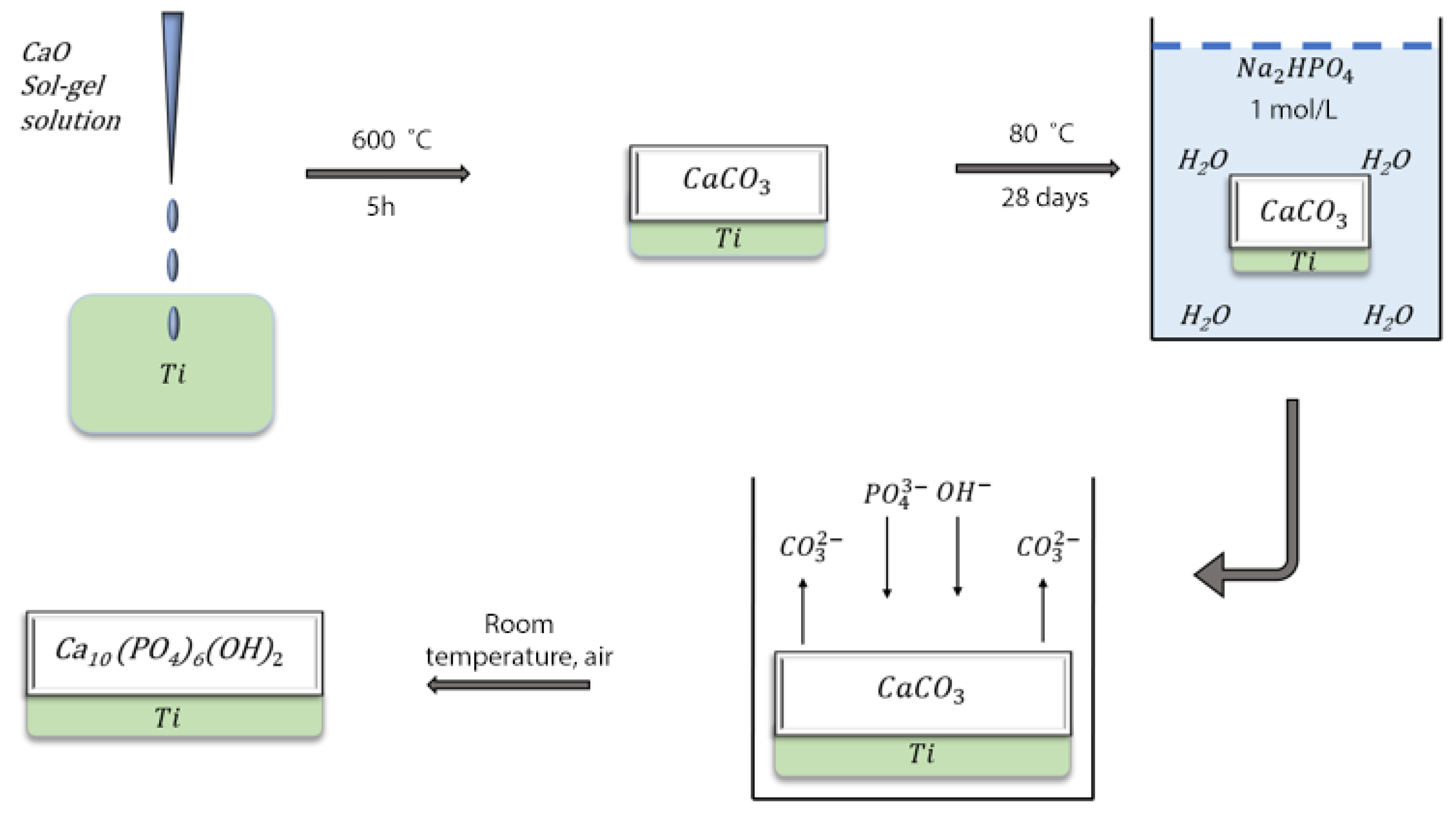
3.1. Materials and Synthesis

CHAp coatings were synthesized on a titanium substrate using a spin-coating technique from sol–gel-derived calcium carbonate following the dissolution–precipitation reaction at low temperatures. To prepare the Ca-O precursor solution, 20 mL of 2-propanol (C3H8O, 99.0%, Alfa Aesar, Haverhill, MA, USA) was mixed with 1.8 mL of acetylacetone (C5H8O2, 99.9%, Merck, Roway, NJ, USA) at room temperature. A total of 1.1 g of calcium nitrate tetrahydrate (Ca(NO3)2∙4H2O, 99.0%, Fluka, Buchs, Switzerland) was added to the resulting solution and stirred for 1 h. The resulting solution was mixed with PVA ([-CH2CHOH-]n, 99.5%, Aldrich, Burlington, MA, USA) at a ratio of 5:3 (v/v) [37]. The obtained Ca-O precursor solution was used for the synthesis of calcium carbonate coatings on the Ti substrate at 600 °C by the spin-coating technique. Finally, the synthesized CaCO3 thin films were immersed in a 1 M Na2HPO4 solution for 28 days at 80 °C. A schematic diagram of the preparation of CHAp coatings is shown in Figure 12. The titanium substrates (Alfa Aesar, 1 mm titanium alloy sheet, 15 mm diameter, 0.5 mm thick discs and 10 × 10 mm squares) before the deposition of Ca-O precursor solution were carefully mechanically polished with 600-, 800- and 1200-grit sandpaper wet with ethanol-based oil (Struers, DP–Lubricant Brown, Cleveland, OH, USA). During the mechanical polishing of the surface, the oxide film formed in the air and surface defects were removed. The polished substrates were immersed in a 5 M NaOH solution and left at a temperature of 60 °C for 24 h. Before the deposition procedure, the substrates were washed with distilled water and dried at room temperature.
During the spin-coating process, several drops of the precursor solution were placed onto the substrates and spin-coated for 30 s @ 3000 rpm (acceleration was 1000 rpm/s). After each spin-coating procedure, the samples were dried for 10 min in the oven at 200 °C. Finally, the samples were annealed for 5 h at 600 °C (with a heating rate of 5 °C/min.). Spin-coating and annealing procedures were repeated 10 and 20 times.

3.2. Characterization

To determine the phase purity of synthesized products, X-ray diffraction (XRD) measurements were performed with Rigaku miniFlex II or SmartLab (Rigaku) diffractometers using Cu Kα1 radiation. Raman spectroscopy studies were performed using a scanning near-field spectroscopy system with a Raman spectroscopy attachment (Alpha300R, WiTec, Ulm, Germany). Infrared spectra were obtained with an FTIR spectrophotometer Perkin Elmer Spectrum TWO with an ATR accessory. In order to study the morphology of the samples, a field-emission scanning electron microscope (FE-SEM) Hitachi SU-70 (FE-SEM, Hitachi, Tokyo, Japan) was used. Surface morphology images of coatings on titanium substrates were also obtained using an optical 3D profilometer Contour GT-K (Bruker, Billerica, MA, USA). This system works in non-contact mode using white-light and phase-shift interferometry. A 3D profilometer creates an electrical topographic image of the surface. The scanned area of the samples was 0.25 mm2. Electrochemical measurements were performed using an electrochemical measurement system, Solartron 1280C (Ametek, Inc., Berwyn, PA, USA), and a three-electrode cell. The auxiliary electrode was a ~4 cm2 platinum plate. A standard electrode of Ag/AgCl in a saturated KCl solution was used as the reference electrode, and a titanium pad was used as the working electrode. The working electrode was installed in a special window of the cell in such a way that only one side of the electrode was in contact with the solution and tightened through a silicone gasket. Contact with the coating was achieved through a Pt wire that was pressed against the electrode surface. The electrochemical cell was filled with Hanks’ balanced salt solution (Sigma-Aldrich, St. Louis, MO, USA).

4. Conclusions

In this study, a low-temperature synthetic approach including sol–gel and dissolution–precipitation procedures was developed for the fabrication of calcium hydroxyapatite (CHAp) coatings on a titanium substrate. A spin-coating method was used for the formation of calcium carbonate layers from the Ca-O precursor solution. The final step of the synthesis of calcium carbonate coatings on the Ti substrate was performed at 600 °C. Finally, the synthesized CaCO3 thin films were immersed in a 1 M Na2HPO4 solution for 28 days at 80 °C to obtain the CHAp phase. The structural properties, phase purity and morphology of the formed coatings were evaluated by X-ray diffraction analysis, FTIR and Raman spectroscopies, SEM and 3D optical profilometry. It was determined that CHAp with a small number of side phases formed on the titanium substrate. In the Raman and FTIR spectra, the characteristic CHAp absorption bands were observed. The CHAp surface formed on the Ti substrate was rough and porous with homogenously distributed plate-like crystals and spherical particles. The results of the investigation of the surface morphology of CHAp films observed by optical 3D profilometer partially correlated with morphological features determined by SEM analysis. The corrosion behaviour of CHAp coatings in Hanks’ solution was also evaluated. The CHAp coating increased the corrosion resistance of the titanium substrate. Additionally, the analysis of the corrosion behaviour and parameters of the electrochemical tests showed that the protective capacity of CHAp coatings obtained by the sol–gel and dissolution–precipitation methods was sufficiently high and increased after a CHAp coating of uniform thickness was formed. These CHAp thin films obtained by the suggested synthesis method may be potential candidates for use in the development of bone implants and different sensors for various analytes.

Author Contributions

Conceptualization, R.K. and A.K.; methodology, R.K.; software, A.Z.; formal analysis, G.B.; investigation, A.P., A.Z. and S.T.; data curation, A.P.; writing—original draft preparation, R.K.; writing—review and editing, A.K.; visualization, G.B.; supervision, A.K.; project administration, A.K.; funding acquisition, A.Z. All authors have read and agreed to the published version of the manuscript.

Funding

This project has received funding from European Social Fund (project No 09.3.3-LMT-K-712-19-0069) under grant agreement with the Research Council of Lithuania (LMTLT). Vilnius University is highly acknowledged for support from the Science Promotion Foundation (project no. MSF-JM-5/2021).

Data Availability Statement

Not applicable.

Conflicts of Interest

The authors declare no conflict of interest.

References

  1. Ishikawa, K.; Garskaite, E.; Kareiva, A. Sol–gel synthesis of calcium phosphate-based biomaterials—A review of environmentally benign, simple, and effective synthesis routes. J. Sol-Gel Sci. Technol. 2020, 94, 551–572. [Google Scholar] [CrossRef]
  2. Fox, K.; Tran, P.A.; Tran, N. Recent Advances in Research Applications of Nanophase Hydroxyapatite. ChemPhysChem 2012, 13, 2495–2506. [Google Scholar] [CrossRef] [PubMed]
  3. Nayak, B.; Samant, A.; Misra, P.K.; Saxena, M. Nanocrystalline Hydroxyapatite: A Potent Material for Adsorption, Biological and Catalytic Studies. Mater. Today Proc. 2019, 9, 689–698. [Google Scholar] [CrossRef]
  4. Desbord, M.; Soulie, J.; Rey, C.; Combes, C. Tunable Behavior in Solution of Amorphous Calcium Ortho/ Pyrophosphate Materials: An Acellular In Vitro Study. ACS Biomater. Sci Eng. 2022, 8, 2363–2374. [Google Scholar] [CrossRef] [PubMed]
  5. Mahabole, M.P.; Aiyer, R.C.; Ramakrishna, C.V.; Sreedhar, B.; Khairnar, R.S. Synthesis, characterization and gas sensing property of hydroxyapatite ceramic. Bull. Mater. Sci. 2005, 28, 535–545. [Google Scholar] [CrossRef] [Green Version]
  6. Monkawa, A.; Ikoma, T.; Yunoki, S.; Yoshioka, T.; Tanaka, J.; Chakarov, D.; Kasemo, B. Fabrication of hydroxyapatite ultra-thin layer on gold surface and its application for quartz crystal microbalance technique. Biomaterials 2006, 27, 5748–5754. [Google Scholar] [CrossRef]
  7. Petrucelli, G.C.; Kawachi, E.Y.; Kubota, L.T.; Bertran, C.A. Hydroxyapatite-based electrode: A new sensor for phosphate. Anal. Commun. 1996, 33, 227–229. [Google Scholar] [CrossRef]
  8. Park, C.S.; Ha, T.H.; Kim, M.; Raja, N.; Yun, H.-S.; Sung, M.J.; Kwon, O.S.; Yoon, H.; Lee, C.-S. Fast and sensitive near-infrared fluorescent probes for ALP detection and 3d printed calcium phosphate scaffold imaging in vivo. Biosens. Bioelectron. 2018, 105, 151–158. [Google Scholar] [CrossRef]
  9. Lahrich, S.; El Mhammedi, M.A. Review—Application of Deficient Apatites Materials in Electrochemical Detection of Heavy Metals: Case of Mercury (II) in Seawater and Fish Samples. J. Electrochem. Soc. 2019, 166, B1567–B1576. [Google Scholar] [CrossRef]
  10. Casado, G.E.; Ivanchenko, P.; Paul, G.; Bisio, C.; Marchese, L.; Ashrafi, A.M.; Milosavljevic, V.; Degli Esposti, L.; Iafisco, M.; Mino, L. Surface and structural characterization of Cu-exchanged hydroxyapatites and their application in H2O2 electrocatalytic reduction. Appl. Surf. Sci. 2022, 595, 153495. [Google Scholar] [CrossRef]
  11. Neacsu, I.A.; Arsenie, L.V.; Trusca, R.; Ardelean, I.L.; Mihailescu, N.; Mihailescu, I.N.; Ristoscu, C.; Bleotu, C.; Ficai, A.; Andronescu, E. Biomimetic Collagen/Zn2+-Substituted Calcium Phosphate Composite Coatings on Titanium Substrates as Prospective Bioactive Layer for Implants: A Comparative Study Spin Coating vs. MAPLE. Nanomaterials 2019, 9, 692. [Google Scholar] [CrossRef] [PubMed] [Green Version]
  12. Singh, R.P.; Batra, U. Apatitic Nanopowders and Coatings: A Comprehensive Review. Surf. Rev. Lett. 2021, 29, 2230004. [Google Scholar] [CrossRef]
  13. Puurunen, R.L. Surface chemistry of atomic layer deposition: A case study for the trimethylaluminum/water process. J. Appl. Phys. 2005, 97, 121301. [Google Scholar] [CrossRef]
  14. Surmenev, R.A.; Surmeneva, M.A.; Grubova, I.Y.; Chernozem, R.V.; Krause, B.; Baumbach, T.; Loza, K.; Epple, M. RF magnetron sputtering of a hydroxyapatite target: A comparison study on polytetrafluorethylene and titanium substrates. Appl. Surf. Sci. 2017, 414, 335–344. [Google Scholar] [CrossRef]
  15. Mostafa, N.Y.; Kamel, M.M. Enhancement of adhesion bonding between titanium metal and electrodeposited calcium phosphate. Surf. Eng. Appl. Electrochem. 2016, 52, 520–523. [Google Scholar] [CrossRef]
  16. Ishikawa, K.; Kareiva, A. Sol–gel synthesis of calcium phosphate-based coatings–A review. CHEMIJA 2020, 31, 25–41. [Google Scholar] [CrossRef]
  17. Munir, M.U.; Salman, S.; Ihsan, A.; Elsaman, T. Synthesis, Characterization, Functionalization and Bio-Applications of Hydroxyapatite Nanomaterials: An Overview. Int. J. Nanomed. 2022, 17, 1903–1925. [Google Scholar] [CrossRef] [PubMed]
  18. Chai, C.S.; Ben-Nissan, B. Bioactive nanocrystalline sol-gel hydroxyapatite coatings. J. Mater. Sci. Mater. Electron. 1999, 10, 465–469. [Google Scholar] [CrossRef]
  19. Usinskas, P.; Stankeviciute, Z.; Beganskiene, A.; Kareiva, A. Sol-gel derived porous and hydrophilic calcium hydroxyapatite coating on modified titanium substrate. Surf. Coatings Technol. 2016, 307, 935–940. [Google Scholar] [CrossRef]
  20. Ishikawa, K. Carbonate apatite bone replacement: Learn from the bone. J. Ceram. Soc. Jpn. 2019, 127, 595–601. [Google Scholar] [CrossRef]
  21. Grigoraviciute-Puroniene, I.; Tanaka, Y.; Vegelyte, V.; Nishimoto, Y.; Ishikawa, K.; Kareiva, A. A novel synthetic approach to low-crystallinity calcium deficient hydroxyapatite. Ceram. Int. 2019, 45, 15620–15623. [Google Scholar] [CrossRef]
  22. Sun, Y.; Wang, G.; Chen, X.; Li, W.; Umemoto, S.; Tajika, M.; Osaka, A. In vitro Assessment of Calcite-Hydroxyapatite Conversion of 3D-Printed Cube Honeycombs in Dilute Phosphate Solutions in the Neutral pH Range. J. Mater. Res. Technol. 2022, in press. [Google Scholar] [CrossRef]
  23. Lukong, V.T.; Ukoba, K.; Jen, T.-C. Review of self-cleaning TiO2 thin films deposited with spin coating. Int. J. Adv. Manuf. Technol. 2022, 122, 3525–3546. [Google Scholar] [CrossRef]
  24. Choi, G.; Choi, A.H.; Evans, L.A.; Akyol, S.; Ben-Nissan, B. A review: Recent advances in sol-gel-derived hydroxyapatite nanocoatings for clinical applications. J. Am. Ceram. Soc. 2020, 103, 5442–5453. [Google Scholar] [CrossRef]
  25. Karalkevičienė, R.; Briedytė, G.; Murauskas, T.; Norkus, M.; Žarkov, A.; Yang, J.-C.; Kareiva, A. A novel method for the formation of bioceramic nano-calcium hydroxyapatite coatings using sol-gel and dissolution-precipitation processing. CHEMIJA 2022, 33, 27–34. [Google Scholar] [CrossRef]
  26. Pawlewicz, W.T.; Exarhos, G.J.; Conaway, W.E. Structural characterization of TiO2 optical coatings by Raman spectroscopy. Appl. Opt. 1983, 22, 1837–1840. [Google Scholar] [CrossRef]
  27. Legodi, M.; de Waal, D.; Potgieter, J.; Potgieter, S. Rapid determination of CaCO3 in mixtures utilising FT—IR spectroscopy. Miner. Eng. 2001, 14, 1107–1111. [Google Scholar] [CrossRef]
  28. Grigoraviciute-Puroniene, I.; Stankeviciute, Z.; Ishikawa, K.; Kareiva, A. Formation of calcium hydroxyapatite with high concentration of homogeneously distributed silver. Microporous Mesoporous Mater. 2019, 293, 109806. [Google Scholar] [CrossRef]
  29. Garskaite, E.; Gross, K.-A.; Yang, S.-W.; Yang, T.C.-K.; Yang, J.-C.; Kareiva, A. Effect of processing conditions on the crystallinity and structure of carbonated calcium hydroxyapatite (CHAp). Crystengcomm 2014, 16, 3950–3959. [Google Scholar] [CrossRef]
  30. Nguyen, T.-L.; Tseng, C.-C.; Cheng, T.-C.; Nguyen, V.-T.; Chang, Y.-H. Formation and characterization of calcium phosphate ceramic coatings on Ti-6Al-4V alloy. Mater. Today Commun. 2022, 31, 103686. [Google Scholar] [CrossRef]
  31. Gao, F.; Chen, X.; Tanaka, H.; Nishitani, A.; Wang, Q. Alkaline phosphatase mediated synthesis of carbon nanotube–hydroxyapatite nanocomposite and its application for electrochemical determination of luteolin. Adv. Powder Technol. 2016, 27, 921–928. [Google Scholar] [CrossRef]
  32. Ortiz, S.L.; Lugo, V.R.; Salado-Leza, D.; Reyes-Valderrama, M.I.; Alcántara-Quintana, L.E.; González-Martínez, P.; Anaya, D.M. Dy2O3-unpurified hydroxyapatite: A promising thermoluminescent sensor and biomimetic nanotherapeutic. Appl. Phys. A 2021, 127, 893. [Google Scholar] [CrossRef]
  33. Kollenda, S.; Kopp, M.; Wens, J.; Koch, J.; Schulze, N.; Papadopoulos, C.; Pöhler, R.; Meyer, H.; Epple, M. A pH-sensitive fluorescent protein sensor to follow the pathway of calcium phosphate nanoparticles into cells. Acta Biomater. 2020, 111, 406–417. [Google Scholar] [CrossRef]
  34. Prichodko, A.; Enrichi, F.; Stankeviciute, Z.; Benedetti, A.; Grigoraviciute-Puroniene, I.; Kareiva, A. Study of Eu3+ and Tm3+ substitution effects in sol–gel fabricated calcium hydroxyapatite. J. Sol-Gel Sci. Technol. 2016, 81, 261–267. [Google Scholar] [CrossRef]
  35. Merkl, P.; Aschtgen, M.-S.; Henriques-Normark, B.; Sotiriou, G.A. Biofilm interfacial acidity evaluation by pH-Responsive luminescent nanoparticle films. Biosens. Bioelectron. 2021, 171, 112732. [Google Scholar] [CrossRef]
  36. Li, Y.; Fu, Y.; Zhang, H.; Song, J.; Yang, S. FITC-Labeled Alendronate as an In Vivo Bone pH Sensor. BioMed Res. Int. 2020, 2020, 4012194. [Google Scholar] [CrossRef]
  37. Zarkov, A.; Stanulis, A.; Sakaliuniene, J.; Butkute, S.; Abakeviciene, B.; Salkus, T.; Tautkus, S.; Orliukas, A.F.; Tamulevicius, S.; Kareiva, A. On the synthesis of yttria-stabilized zirconia: A comparative study. J. Sol-Gel Sci. Technol. 2015, 76, 309–319. [Google Scholar] [CrossRef]
Figure 1. The XRD patterns of CaCO3 coatings obtained by spin coating on a Ti substrate after 20 of spin-coating and thermal treatment procedures. Diffraction peaks: *—CaCO3 (ICDD 01-086-2339), ▲—CaTiO3 (ICDD 03-065-3287), ○—CaO (ICDD 01-082-1691), ●—TiO2 (ICDD 01-083-2241).
Inorganics 11 00033 g001
Figure 2. XRD patterns of CHAp coating obtained after immersion of CaCO3 coating for 28 days in Na2HPO4 solution (1) and Ti substrate annealed at 600 °C (2). Diffraction reflections are marked: ♦—CHAp (ICDD 00-054-0022), *—Na2HPO4 (ICDD 01-076-2287), ■—Ti (ICDD 01-089-5009), ●—TiO2 (ICDD 01-076-0318).
Inorganics 11 00033 g002
Figure 3. Raman spectra of CaCO3 (top) and CHAp (bottom) coatings.
Inorganics 11 00033 g003
Figure 4. FTIR spectra of CaCO3 (top) and CHAp (bottom) coatings.
Inorganics 11 00033 g004
Figure 5. SEM micrographs of CaCO3 coating obtained at different magnifications.
Inorganics 11 00033 g005
Figure 6. SEM micrographs of CHAp coating obtained at different magnifications.
Inorganics 11 00033 g006
Figure 7. SEM micrographs of CHAp coating obtained after annealing at 900 °C.
Inorganics 11 00033 g007
Figure 8. The results of optical 3D profilometry for Ti substrate (top) and CaCO3 coating (bottom): optical 3D (A) and 2D contour (B) images and roughness (C) profiles.
Inorganics 11 00033 g008
Figure 9. The results of optical 3D profilometry for the as-prepared CHAp coating (top) and that annealed at 900 °C (bottom): optical 3D (A) and 2D contour (B) images and roughness (C) profiles.
Inorganics 11 00033 g009
Figure 10. Exposure time dependences of the Eocp potential of titanium/CHAp films in Hanks’ solution: 1—annealed Ti substrate, 2—CHAp coating, 3—CHAp coating after annealing at 900 °C.
Inorganics 11 00033 g010
Figure 11. Tafel dependencies: 1—heated Ti substrate, 2—CHAp coating, 3—CHAp coating after annealing at 900 °C.
Inorganics 11 00033 g011
Figure 12. The schematic diagram of preparation of CHAp coatings on Ti substrate using low-temperature sol–gel and dissolution–precipitation methods.
Inorganics 11 00033 g012
Table 1. Corrosion parameters of the investigated coatings.
Samplebc, Vba, Vjcorr, A·cm−2
Ti substrate0.02090.01632.27 × 10−8
CHAp coating0.03020.01543.34 × 10−8
CHAp coating annealed at 900 °C0.04200.01061.82 × 10−7
Disclaimer/Publisher’s Note: The statements, opinions and data contained in all publications are solely those of the individual author(s) and contributor(s) and not of MDPI and/or the editor(s). MDPI and/or the editor(s) disclaim responsibility for any injury to people or property resulting from any ideas, methods, instructions or products referred to in the content.

