Article

High Value-Added Utilization of Waste Hydrodesulfurization Catalysts: Low-Cost Synthesis of Cathode Materials for Lithium-Ion Batteries

School of Chemical Engineering, Sichuan University, Chengdu 610065, China
*
Author to whom correspondence should be addressed.
Separations 2022, 9(12), 449; https://doi.org/10.3390/separations9120449
Submission received: 15 November 2022 / Revised: 10 December 2022 / Accepted: 14 December 2022 / Published: 19 December 2022
(This article belongs to the Special Issue Efficient and Green Recovery of Metal Minerals)

Abstract

:
This work introduces a one-step method for the preparation of layered oxide cathode materials utilizing pure Ni and Co mixed solution obtained from the waste hydrodesulfurization (HDS) catalyst. An efficient non-separation strategy with pyrometallurgical-hydrometallurgical (pyro-hydrometallurgical) process consisting of roasting and leaching is proposed. Most of the impurity metal elements such as Mo and V were removed by simple water leaching after the waste HDS catalyst was roasted with Na2CO3 at 650 °C for 2.5 h. Additionally, 93.9% Ni and 100.0% Co were recovered by H2SO4 leaching at 90 °C for 2.5 h. Then, LiNi0.533Co0.193Mn0.260V0.003Fe0.007Al0.004O2 (C–NCM) was successfully synthesized by hydroxide co-precipitation and high temperature solid phase methods using the above Ni and Co mixed solution. The final C–NCM material exhibits excellent electrochemical performance with a discharge specific capacity of 199.1 mAh g−1 at 0.1 C and a cycle retention rate of 79.7% after 200 cycles at 1 C. This novel process for the synthesis of cathode material can significantly improve production efficiency and realize the high added-value utilization of metal resources in a waste catalyst.

1. Introduction

Millions of tons of refinery catalyst are scrapped every year with the gradual improvement of the secondary processing capacity of crude oil in the world petroleum industry [1]. In the petroleum refining process, these catalysts are used to remove sulfur, nitrogen and other metals from the crude oil structure [2]. They are generally Al2O3-based and contain metals such as Mo, Co and Ni [3]. The activity of the catalyst decreases gradually under the action of high temperature, heavy metal or water vapor [4]. After a certain regeneration cycle, the activity of the regenerated catalyst could not eventually meet reaction requirements. At present, most of the waste refining catalysts were buried underground. Underground burial caused the loss of silicon, aluminum and heavy metal resources, resulting in serious groundwater and soil pollution [2,5]. Therefore, developing efficient recycling technology of waste oil refining catalyst for its high value-added utilization has great significance to the environment and economy.
Many researchers have proposed various methods for recovering valuable metals from waste catalysts based on pyrometallurgy and hydrometallurgy processes [6,7,8,9]. Thi et al. [10] reported a process for recovering molybdenum and cobalt from spent hydrodesulfurization catalysts. The process includes HCl leaching, followed by solvent extraction to gradually separate molybdenum, cobalt, iron and aluminum from the leaching solution, and then stripping Mo and Co from the loaded organic phase by dilute hydrochloric acid solution and distilled water. The process recovers approximately 96.0% molybdenum and 93.0% cobalt. Busnardo et al. [11] studied a recycling route for spent hydrofining (HDR) catalysts. The route is based on the fusion of sample and KHSO4. The fused solids are then dissolved in deionized water (90–100 °C). Then cobalt, nickel, molybdenum and aluminum were recovered by conventional precipitation method or selective solvent extraction method, and the yield was at least 85.0%. A process combining selective leaching, chemical precipitation and cementation to recover nickel and aluminum from spent Ni/Al2O3 methanation catalysts was proposed by Moosakazemi et al. [12]. First, nickel compounds were separated from catalyst support matrix by NaOH leaching method, then nickel was extracted by HCl leaching method, and Al(OH)3 was separated from alkaline solution by chemical precipitation method. Finally, nickel in chloride medium was successfully recovered by chemical precipitation method and cementation method using sodium hydroxide and aluminum powder respectively. Li et al. [13] proposed a new method for extracting vanadium and chromium from environmentally friendly vanadium-chromium slag based on step-by-step roasting, which consists of a sodium roasting-water leaching two-stage process. Vanadium was first extracted from vanadium-chromium slag by sodium roasting-water leaching method, and then chromium was leached by secondary roasting of the leaching slag in the roasting stage. The extraction rates of vanadium and chromium were 87.9% and 96.4%, respectively. In the process of hydrometallurgy, the pretreatment of waste catalyst such as oxidation and calcination could ensure that precious metals enter the solution in a high yield. However, complex separation and purification processes [14,15] were often required to recover the target metal with high purity, which undoubtedly increased the recovery cost and reduced the economic compensation benefit [16]. If the recovered mixed solution of valuable metals could be directly used as a raw material for synthesizing other high value-added products, the traditional recovery process would be greatly simplified.
Recently, new energy vehicles have ushered in unprecedented development opportunities with the proposal of “Carbon Peak and Carbon Neutrality” in China. Lithium-ion batteries (LIBs) have aroused extensive attention as the clean and renewable electrochemical energy storage equipment for portable electronic products and electric vehicles [17]. Currently, the main cathode materials for commercial LIBs were LiCoO2 [18], LiFePO4 [19] and LiNixMnyCozO2 (NCM) [20]. Among them, NCM cathode materials have become a hot growing trend for their high energy density and excellent rate performance [21]. However, the development of NCM cathode materials were limited due to the globalization of the mineral resource crisis and the high cost of purity nickel and cobalt salts. HDS catalysts for petroleum refining usually contained a large amount of heavy metals including Mo, V, Ni, Co and their compounds [22]. Since HDS catalysts contain a large amount of heavy metals, they could become an important secondary metal resource after deactivation. Ni and Co could be selectively recovered from the waste HDS catalyst by an appropriate metallurgical process into the solution, and directly used as a synthetic raw material for NCM cathode materials. In the process of recycling waste catalyst, the trace elements in the leaching solution could play the role of element doping, thus significantly improving the electrochemical performance of NCM materials [23,24,25].
The purpose of this study was to achieve efficient recovery and high value-added utilization of valuable metals from waste catalysts. In this article, high purity nickel-cobalt mixed solution obtained from waste catalyst was directly used to synthesize cathode material precursor by hydroxide co-precipitation method. This one-step method omitted the separation, purification and crystallization for the reutilization of Ni and Co elements. The cathode material had a discharge specific capacity of 170.1 mAh g−1 and a cycle retention rate of 79.7% after 200 cycles at 1 C. This novel process skillfully combined the synthesis of cathode materials with the recovery of waste catalysts, while realizing the economical utilization of the transition metals and providing a new raw material for NCM cathode materials.

2. Experimental

2.1. Materials and Characterization Methods

HDS catalysts are widely used in the petroleum refining industry and they are usually composed of molybdenum supported on an alumina carrier with promoters such as cobalt or nickel. HDS catalysts are deactivated by carbon, sulfur and metal deposits and become solid wastes classified as hazardous. The waste catalyst for this experiment from Sichuan Shunying Power Battery Material Co., Ltd. (Meishan, Sichuan, China). The composition of the waste HDS catalyst used in this work was analyzed by X-ray fluorescence (XRF, S8 TIGER, Germany) and the results are shown in Table 1. Reagents such as Na2CO3 and H2SO4 were purchased from Chengdu Cologne. Particle morphology and structure were measured by scanning electron microscope (SEM, S-4800, Hitachi) and the element mapping is performed by energy dispersive spectroscopy (EDS) using the same instrument with the SEM characterization. The concentration of valuable metals in the leachate of the waste catalyst and the composition of the synthesized cathode materials were determined by inductively Coupled Plasma Optical Emission Spectrometry (ICP-OES, 5800, Agilent Technologies Inc., Santa Clara, CA, USA). Powder X-ray diffraction (XRD, PW3071, Philips Company, Amsterdam, The Netherlands) data were collected at 25 °C in the range of 10–80° with a step size of 0.026° using Cu-Kα radiation. The Fullprof program was used for Rietveld refinement. X-ray photoelectron spectroscopy with monochromatic Al-Kα radiation (XPS, Thermo Scientific K-Alpha, America) was used to detect elemental chemical states in materials.
The overall recovery and reutilization processes of waste HDS catalyst were shown in Figure 1, including sodium salt roasting, water leaching and sulfuric acid leaching, and synthesis of NCM cathode materials. The specific steps are explained in detail below.

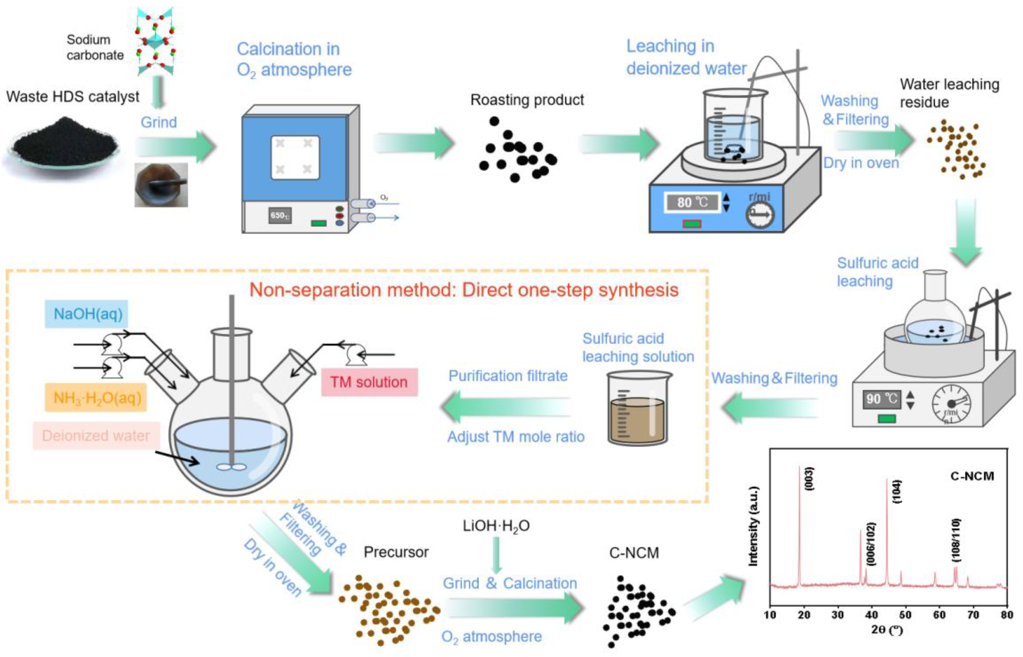
2.2. Experimental Procedure

2.2.1. Sodium Salt Roasting

After the waste HDS catalyst was treated by ball mill for 1 h, the material size distribution was 2–10 µm (Figure S1). Na2CO3 as the roasting additive was then mixed with the waste catalyst powder in a ceramic crucible at a mass ratio of 0.8–1.2: 1 sodium carbonate/waste catalyst (Na/WC). The mixture was placed in a Muffle furnace filled with O2 and heated to 500–700 °C at a rate of 10 °C/min for 1–3 h. Then the roasted mixture was cooled to 25 °C in the furnace. Through the method of Na2CO3 mixed oxidation roasting, the main impurities Mo, V and other metal elements in the waste catalyst were converted into high valence soluble sodium salt (e.g., NaMo2(PO4)3, Na3Mo(P2O7), NaVO3), which was convenient for the subsequent separation.

2.2.2. Leaching in Deionized Water

The particle size of roasted waste HDS catalyst became larger after roasting (Figure S1), and then the roasting product was leached with deionized water at a liquid-solid ratio (L/S) of 10 mL/g. The water leaching experiment was carried out with a water bath of 80 °C for 2 h at a stirring speed of 600 rpm. Then, the leaching solution and residue were separated through filtration. The metal elements of Ni and Co remained in the leaching residue as the insoluble compound, which could be used for subsequent processes of reutilization. The main impurities Mo and V were leached out of the solution. Leaching efficiency of leached valuable metal elements could be calculated as follows:
ω i ( % ) = C i   ×   V i   ×   M i β i ×   m 0   ×   100 %
In Equation (1), ωi is the leaching efficiency of valuable metals, Ci and Vi represent the concentration and volume of leaching solution, respectively. Mi and βi represent the relative atomic mass and mass fraction of metal elements in the waste HDS catalyst, respectively. In addition, m0 represents the total mass of the waste HDS catalyst.

2.2.3. Sulfuric Acid Leaching

The leaching residue obtained from the water leaching experiment was placed in an oven at 120 °C and dried for 12 h. Then dilute H2SO4 was used to soak the water leaching residue at a L/S of 5–25 mL/g. The acid leaching experiment was carried out with a water bath of 50–90 °C for 1–3 h at a stirring speed of 600 rpm. Then, the leaching solution and residue were separated by filtration. The leaching efficiency of metal elements could be calculated according to the above Equation (1). The target metal elements Ni and Co could be effectively extracted by H2SO4 leaching, but there were trace impurities accompanied by leaching.

2.2.4. Titration in Removing Impurity

2 M NaOH solution was used to titrate the pickle liquor obtained by H2SO4 leaching. NaOH solution was added slowly to pickle liquor by peristaltic pump with a stirring speed of 600 rpm. Mettler pH meter was used for monitoring the change of the pH value of the pickling liquid. NaOH solution feeding was stopped when the pH value reached 3.0, and the reaction continued for a period of time until the pH value of the pickle liquor was stable. Through titration experiments, the impurity Fe3+ in the acid leaching solution could be effectively precipitated, thereby further purifying the acid leaching solution to obtain a high-purity Ni and Co mixture solution for direct use in subsequent synthesis experiments.

2.2.5. Precipitation Synthesis and Calcination of NCM523 Precursors

According to the molar ratio (Ni:Co:Mn = 5:2:3), a certain amount of NiSO4·6H2O, CoSO4·7H2O and MnSO4·H2O were added to the purified acid leaching solution to obtain the transition metal salt solution with the concentration of 0.5 M. The synthesis of the precursor was carried out by hydroxide co-precipitation method with 0.5 M NH3·H2O as the complexing agent and 2.0 M NaOH as the precipitant in a batch stirred reactor at a stirring speed of 1000 rpm, a pH value of 10.8 ± 0.05, and a reaction temperature of 50 °C for 8 h under an Ar atmosphere. Then the solid-liquid mixture was filtered and washed with deionized water until the pH of the filtrate approaches 7.0 to obtain the wet C–NCM precursor. Then the wet C–NCM precursor was placed in an oven at 120 °C to dry for 12 h. A certain amount of C–NCM precursor powder was mixed with excess 5% LiOH·H2O (molar ratio: LiOH·H2O/C–NCM(OH)2 = 1.05). The mixed powder was heated to 480 °C at the rate of 2.5 °C/min and kept for 300 min, then heated to 870 °C at the same rate and kept for 900 min, and finally cooled to 25 °C in a tubular furnace filled with oxygen to obtain the C–NCM powder. The cathode material LiNi0.53Co0.20Mn0.27O2 (S–NCM) was synthesized by purchased transition metal sulfate mixture solution using the same precursor synthesis and calcination conditions as the control experiment.

2.2.6. Electrochemical Performance Test

The synthesized NCM cathode material was electrochemically evaluated by assembly of a 2025 button cell. The cathode was prepared from a mixture of 80 wt% active material, 13 wt% acetylene black, and 7 wt% polyvinylidene fluoride binder on aluminum foil. After vacuum drying overnight at 120 °C, the electrodes were stamped out of the foil and weighed with a load density of about 2 mg cm−2. The electrolyte consisted of 1.0 M LiPF6 with dissolved ethyl carbonate and dimethyl carbonate (volume ratio, 1:1), using Celgard2400 as the diaphragm and lithium metal as the negative electrode of the half cell. CR2025 coin battery was assembled in a glove box filled with argon gas. The assembled half battery was placed in a constant temperature and humidity room for 12 h to ensure that the electrolyte was fully infiltrated into the half battery. The NEWWARE battery program was used to test electrochemical performance at 25 °C with a voltage window of 2.7–4.3 V (1 C = 160 mA g−1).

3. Results and Discussion

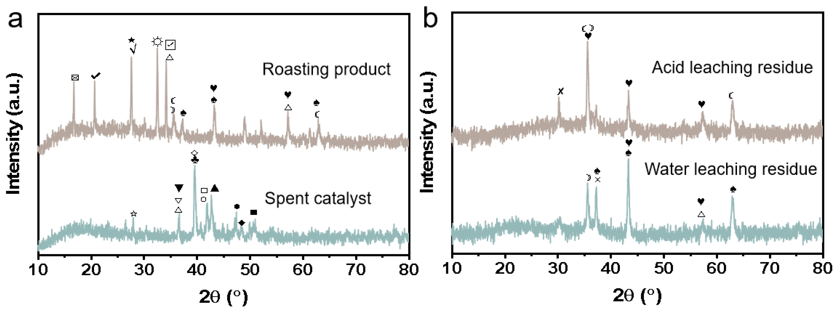
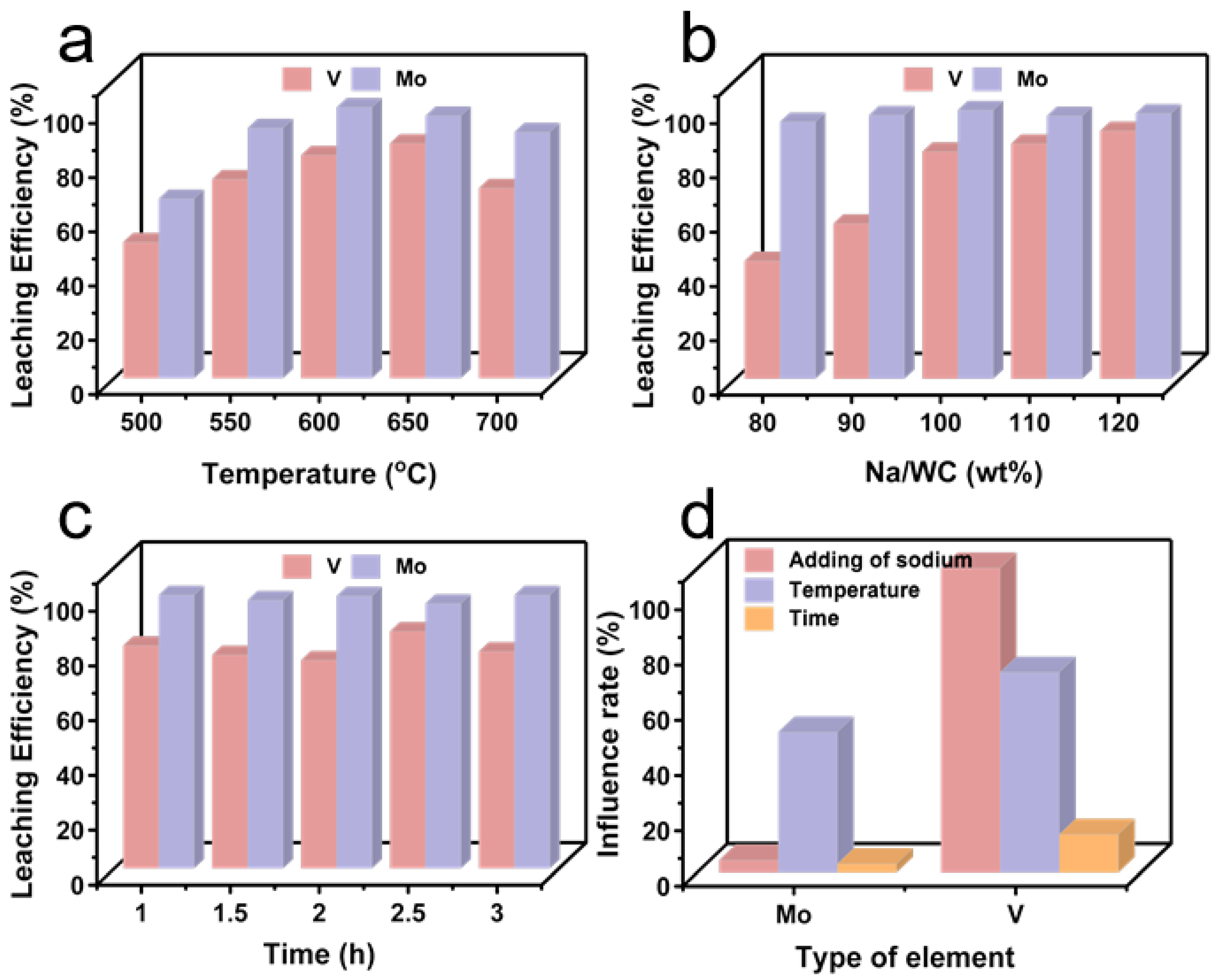
3.1. Mixed Oxidation Roasting of Waste HDS Catalyst with Na2CO3

Figure 2a shows the XRD patterns of waste HDS catalyst and roasting product. Ni, Co, Mo, V and other metal elements in the waste catalyst mainly exist in the form of composite metal phosphides and oxides. After roasting, Mo, V and other impurity metal elements mainly exist in the form of NaMo2(PO4)3, Na3Mo(P2O7), NaVO3 and other high valence soluble sodium salts. Meanwhile, the target metals Ni and Co are also successfully released from the composite metal compound, existing in the form of insoluble oxides.
In order to make Mo, V and other impurity metal elements that can be effectively leached, the roasting temperature, Na2CO3 addition amount and roasting time are systematically investigated, and the results are shown in Figure 3. Figure 3a shows the influence of roasting temperature on the leaching efficiency for major metal elements in the waste HDS catalyst. When calcination is carried out at 500 °C, the leaching efficiency of Mo and V are 66.3% and 50.3%, respectively. With the increase of calcination temperature at 550 °C, 600 °C and 650 °C, the leaching efficiencies of Mo and V increase to more than 90.0% and 70.0%, respectively. However, the leaching efficiencies of Mo and V decrease when the temperature rises to 700 °C. This can be attributed to the formation of silicates that inhibit the leaching of metallic elements [26]. As shown in Figure 3b, it can be seen that the addition of Na2CO3 has little effect on the leaching efficiency of Mo. On the contrary, the leaching efficiency of V increases with the increasing amount of Na2CO3, while the increase rate of V leaching efficiency gradually slows down when the amount of Na2CO3 exceeds 100.0%, which can be attributed to the gradual saturation of the reactions of Mo, V and Na2CO3 in the waste catalyst. The effect of roasting time is shown in Figure 3c. The roasting time has no significant effect on the leaching efficiencies of Mo and V, and the leaching efficiency of V reaches the highest when roasting time is 2.5 h. Moreover, roasting temperature, roasting time and Na/WC mass ratio have little effect on the leaching efficiency of Ni, Co and Fe (Table S1). This is mainly due to the existence of Ni, Co and Fe in the waste catalyst after calcination in the form of almost insoluble oxides in water, which can also be obtained from Figure 2a. In addition, it can be observed from Figure 3d that the roasting temperature has the most significant influence on the leaching of Mo, and the Na/WC mass ratio has the greatest influence on the leaching of V.
Therefore, the optimal conditions for the mixed oxidation roasting of Na2CO3 are as follows: a roasting temperature of 650 °C, a Na/WC mass ratio of 100.0% and a roasting time of 2.5 h. As a result, the major impurity metal elements Mo and V are leached in aqueous solution, and the corresponding leaching efficiencies are 99.8% and 92.8%, respectively. To further recover Mo and V from the water leaching solution, high-purity metal compounds can be extracted by precipitation, extraction, etc. Furthermore, the target metals Ni and Co are retained in the leaching residue.

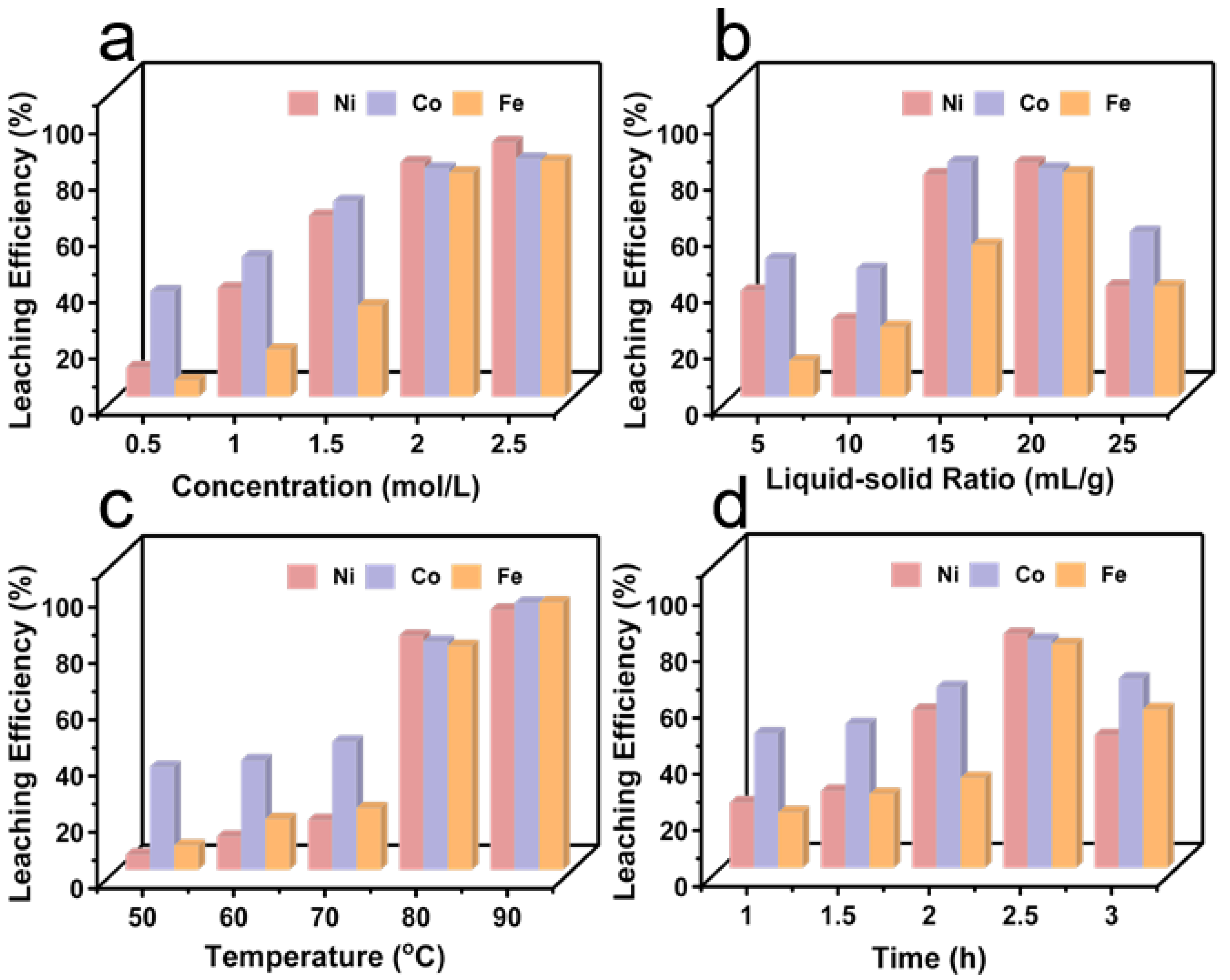
3.2. Sulfuric Acid Leaching and Impurity Removal

Figure 2b shows the XRD patterns of water leaching residue and acid leaching residue. The main form of metal elements in water leaching residue is oxide. In order to obtain Ni and Co mixed leaching solution, H2SO4 is used to treat water leaching residue and leaching conditions are optimized, including H2SO4 (leaching agent) concentration, L/S, leaching temperature and leaching time. The influence of H2SO4 concentration on leaching efficiencies of major metal elements in water leaching residue is studied within the concentration range of 0.5 M to 2.5 M, as shown in Figure 4a. The leaching efficiencies of Ni, Co and Fe rise with the increases of H2SO4 concentration. However, leaching efficiencies of metal elements show little improvement when the concentration increases to more than 2.0 M, because the H2SO4 leaching is gradually saturated. In order to reduce the use of the leaching agent, the optimal concentration of H2SO4 leaching is 2.0 M. Figure 4b displays the influence of L/S on leaching efficiencies of the main metal elements. When the L/S is 10.0, the leaching efficiencies of Ni and Co are 27.6% and 45.5%, respectively, which indicates that H2SO4 cannot effectively leach most metal oxides. When the L/S is 15.0 and 20.0, the leaching efficiencies of Ni and Co reach about 80.0%. The metal leaching efficiency suddenly decreases as the L/S continues to increase, which may be due to the residual silicate in leaching residue dispersed in a large amount of H2SO4 to form H2SiO3 colloid [27]. This colloid is wrapped on the surface of the leaching residue particles and hinders the leaching reaction between NiO or CoO with H2SO4. The leaching efficiency of Fe is improved from 54.1% to 79.7% when the L/S increases from 15.0 to 20.0. The large-scale leaching of impurity Fe is obviously not conducive to subsequent synthesis. In order to reduce the burden of subsequent purification of mixed Ni and Co solution, the optimal L/S is 15.0. The leaching temperature has a great influence on the leaching efficiencies of the main metal elements (Figure 4c). When the temperature is 50 °C, the leaching efficiencies of Ni and Co is only 5.5% and 36.8%, respectively. The leaching efficiencies of Ni and Co have little change as the temperature rises to 70 °C. However, the leaching efficiencies of Ni and Co increase to >80.0%, when the temperature continues to increase to 80 °C. As the temperature increases to 90 °C, the leaching efficiencies of Ni and Co reach 92.6% and 95.1%. This can be attributed to the accelerated diffusion rate of metal ions at higher temperature [26]. Therefore, the optimal leaching temperature is 90 °C. Figure 4d displays the influence of leaching time on leaching efficiencies of main metal elements. When the leaching time is 2.5 h, the optimal leaching efficiencies of Ni and Co are 83.4% and 81.2%, respectively. When the leaching time is further extended to 3 h, the leaching efficiency suddenly decreases. This is attributed to the appearance of SiO3−, which combines with metal cations to form insoluble composite silicates. This silicate seriously hinders the effective leaching of metal elements [28]. Therefore, the optimal leaching time is 2.5 h [26]. The leaching efficiencies of Ni and Co can reach 93.9% and 100.0%, respectively, under the optimal H2SO4 leaching conditions of 2.0 M, 2.5 h, L/S = 15.0 mL/g and 90 °C (Table S2).
Although most of the target metals Ni and Co can be effectively leached from water leaching residue by H2SO4 treatment, similar leaching properties of Fe can also lead to the leaching of large amounts of impurity elements. As shown in Figure S2, the concentration of H2SO4 and leaching temperature have great influence on the leaching of Fe, which are also the key factors restricting the leaching of Ni and Co. In view of the above analysis, we decided, in the experiment, to use acid base titration method to remove the impurity metal elements in the acid leaching solution. Referring to related chemical manuals [29], it is found that the precipitation pH values of Ni2+ → Ni(OH)2 and Co2+ → Co(OH)2 are much higher than that of Fe3+ → Fe(OH)3 (Table S3). According to thermodynamic analysis, the Eh-pH diagram drawn in Figure 5 shows that the stable existence regions of Ni(OH)2, Co(OH)2, Mn(OH)2 and Fe(OH)3 are 6.4 < pH < 14, 6.2 < pH <14, 7.6 < pH < 14 and 1.4 < pH < 14, respectively [30]. Therefore, the main impurity Fe in the acid leaching solution can be removed by slowly adding 2.0 M NaOH solution into the acid leaching solution and controlling the pH of the leaching solution to reach 3.

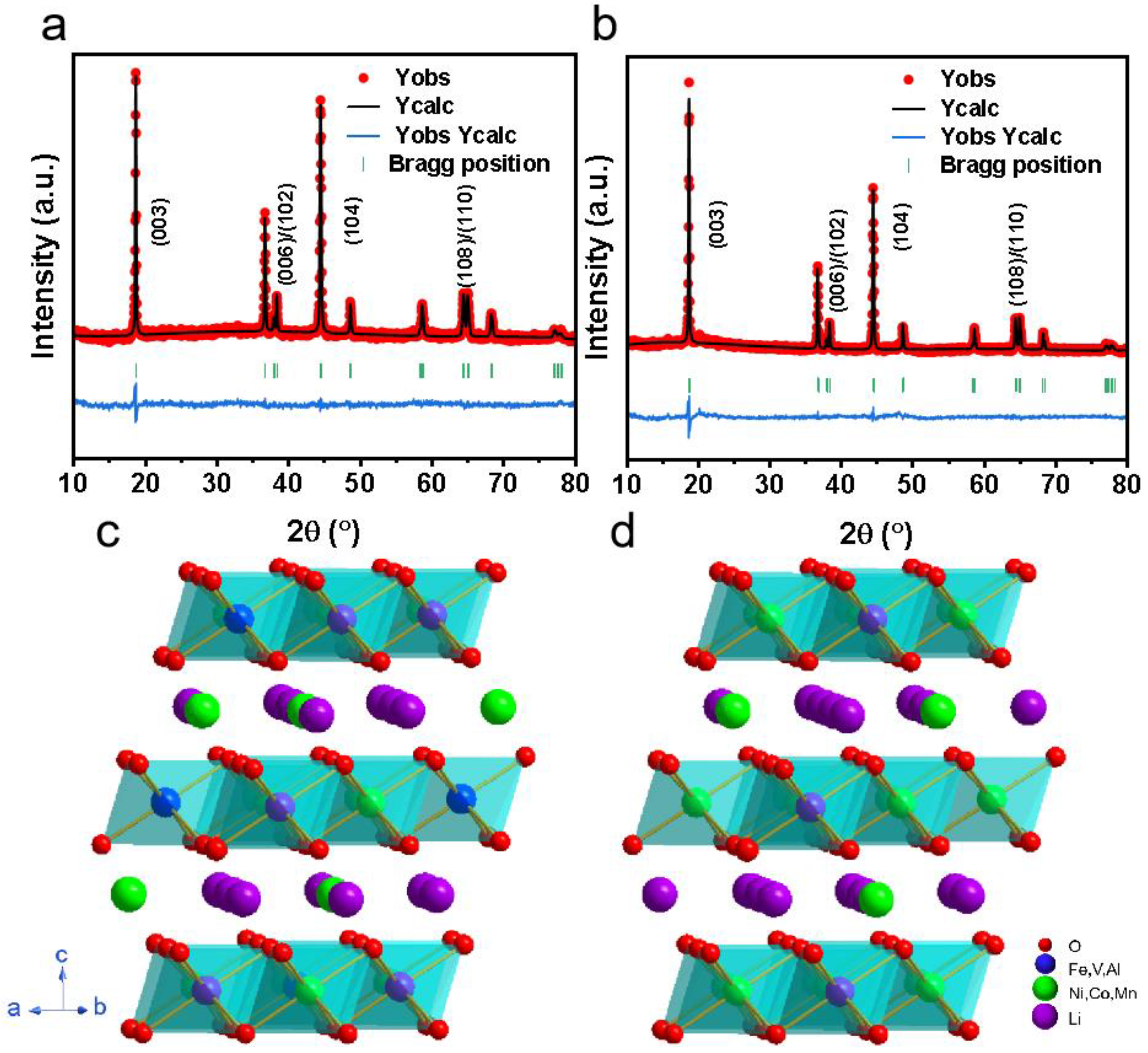
3.3. Characterization of Cathode Materials Prepared by Pickle Liquor

The NCM cathode materials were successfully synthesized by hydroxide co-precipitation and high temperature solid phase method using the above purified pickle liquor with certain concentrations of Ni2+ and Co2+. In order to accurately understand the structural characteristics of the synthetic materials, the Rietveld XRD patterns of C–NCM and S–NCM are shown in Figure 6a, b, and the XRD patterns of all samples are observed within the range of 10–80°. In addition, all samples show similar diffraction peaks and no significant impurity phases are detected, indicating that the synthesized samples all have regular hexagonal α-NaFeO2 structure and R-3m space group [31,32]. In addition, the diffraction peaks of (006)/(102) and (108)/(110) have obvious splitting phenomenon, which indicates that the material has a good, layered structure [33,34]. It can be seen that the structure of the C–NCM material is not damaged by trace impurity elements compared with the S–NCM material. The Rwp values of the two samples observed in Table S4 are below 5.00%, which means that the Rietveld analysis results are acceptable [35]. The a-axis and c-axis of the C–NCM material are slightly different from those of the S–NCM material. The c/a values of the materials are all greater than 4.899, indicating that the layered structure of the materials is not damaged. The I(003)/I(104) strength range of C–NCM is larger than that of S–NCM, which means that C–NCM shows a higher cation mixing ratio [36].
The particle size of C–NCM and S–NCM are both 2–5 µm, with a small amount of agglomeration (Figure 7a,b). The morphology of the two materials shows no significant difference, indicating that the trace impurity elements in the acid leaching solution have little effect on the morphology of the cathode material. EDS mapping of C–NCM and S–NCM is shown in Figure S3. Obviously, the Ni, Co and Mn elements in the two cathode materials are evenly distributed, and the V, Fe and Al elements in C–NCM are also evenly distributed on the material. SEM images and EDS mapping show that some trace impurities (V, Fe, Al) in the acid leaching solution are indeed introduced into C–NCM material during the synthesis process.
In order to further explore the influence of trace impurities in acid leaching solution on the morphology and structure of synthetic materials. TEM images of C–NCM and S–NCM materials are shown in Figure 7c,d. S–NCM exhibits good crystallization, the lattice edge extending to particle boundary and perfect layered structure with 0.236 nm crystal spacing, corresponding to the (006) plane of hexagonal crystal system, as shown in Figure 7c. C–NCM maintains the entire layered structure well, and crystal spacing is 0.471 nm, corresponding to the (003) plane of the hexagonal crystal system, as shown in Figure 7d. In addition, no impurities are observed in the surface area.
In order to study the chemical valence changes of metal elements in the materials, XPS tests are carried out on C–NCM and S–NCM, respectively. Figure S4a–f displays the spectra of Ni 2p, Mn 2p and Co 2p of the two samples, and they show similar curves. Compared with the S–NCM material, the XPS spectra of the C–NCM material shows no obvious peak shift. For the S–NCM sample, the peaks at 855.3 eV and 861.0 eV are attributed to Ni 2p1/2 and the corresponding satellite peak, while for the C–NCM sample, the peaks at 855.4 eV and 861.2 eV are attributed to Ni 2p1/2 and corresponding satellite peak. After fitting the peak of Ni 2p [37,38,39,40,41], the Ni2+ percentage of S–NCM (854.7 eV) is 65.62%, while that of C–NCM (854.7 eV) is 69.58%. These findings are consistent with XRD results. Due to the introduction of high valence impurity metal ions in the synthesis process of C–NCM materials, and in order to balance the ion valence state in the material system, the content of Ni2+ is increased which aggravates the cation mixing. The electron binding energies of Co 2p1/2, Mn 2p3/2 are 795.4 eV, 642.7 eV (S–NCM) and 795.9 eV, 642.9 eV (C–NCM), respectively [23,42,43,44], which are consistent with the reported results of Co and Mn in similar transition metal oxides. Figure S4g–i show the V 2p, Fe 2p and Al 2p spectra of C–NCM [45,46,47,48,49]. This further confirms that impurity elements (V, Fe, Al) in the acid leaching solution are successfully introduced into the cathode material.

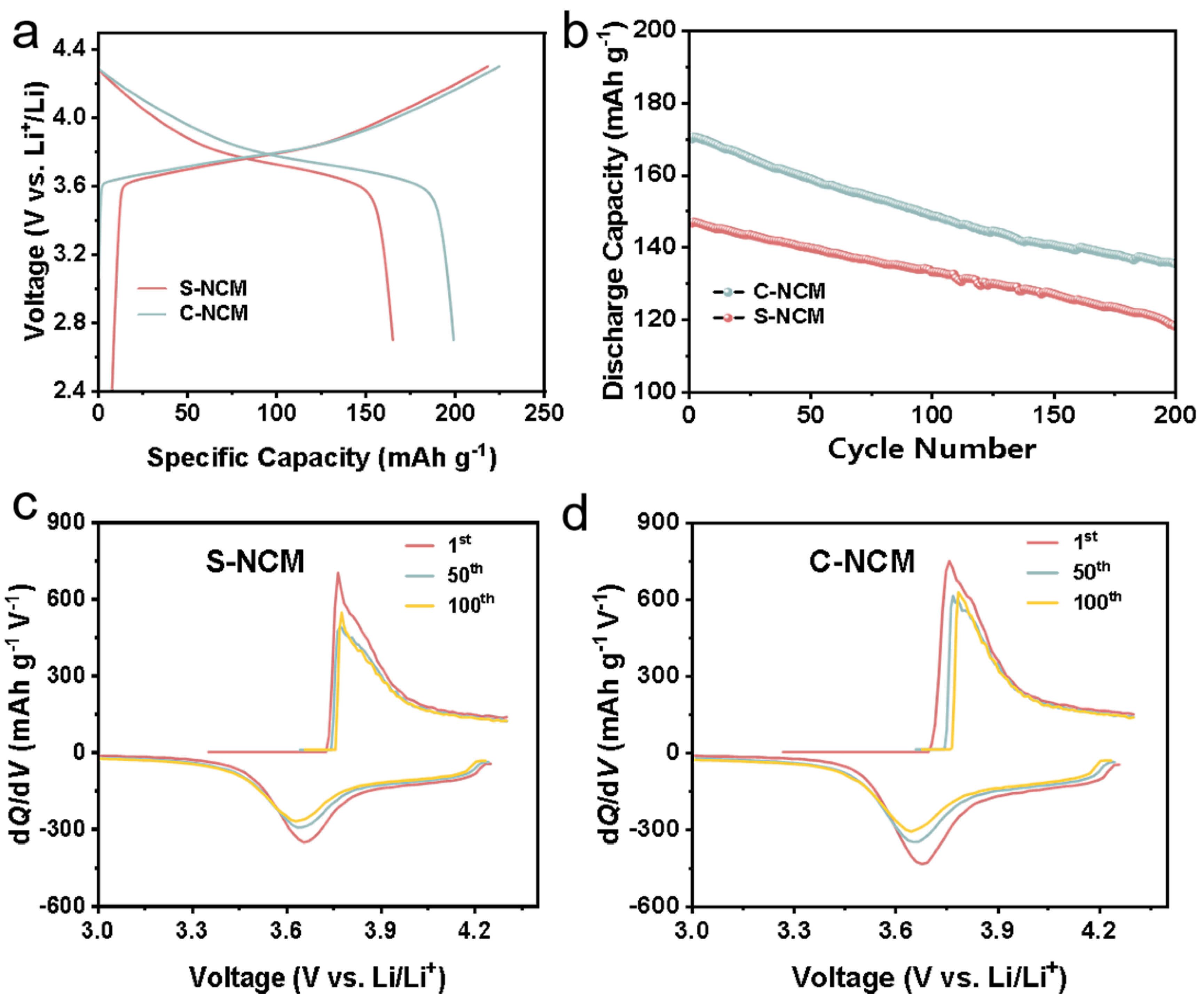
3.4. Electrochemical Performance

Figure 8a displays the initial charge-discharge curves of Li/S–NCM and C–NCM cells at a constant current of 0.1 C (1 C = 160 mA g−1) and a voltage range of 2.7–4.3 V. At a cutoff voltage of 4.3 V, all batteries show very smooth and stable charge-discharge curves. The discharge specific capacity of S–NCM is only 165.2 mAh g−1 and the initial coulomb efficiency is 75.1%, while the discharge specific capacity of C–NCM is 199.1 mAh g−1 and the initial coulomb efficiency is 88.1%. Compared with the standard sample, the C–NCM has a better first charge-discharge performance. According to the electrochemical impedance diagrams of materials (Figure S5), the charge transfer resistance of C–NCM is smaller (156.600 Ω) than that of S–NCM (203.100 Ω) (Table S5), which indicates that C–NCM material has a faster lithiation/delithiation and exhibits better electrochemical reaction kinetics. Thus, the electrochemical capacity of the material is improved [50,51,52].
Figure 8b displays the discharge capacities of S–NCM and C–NCM materials at a constant current of 1 C and a voltage range of 2.7–4.3 V for 200 cycles. Surprisingly, although the discharge capacity of C–NCM is consistently higher than that of the S–NCM throughout the cycle, the capacity retention rate is still 79.7% after 200 cycles, which is very close to the 80.7% capacity retention rate of S–NCM after the same cycle. The results show that C–NCM material not only makes a show of not less than the S–NCM cycle performance, but it also shows excellent electrochemical performance under the condition of the same charge and discharge. This can be attributed to the introduction of trace impurity elements in the synthesis of C–NCM material, which is equivalent to the S–NCM material modified by multi-element doping [53,54,55,56,57,58,59]. Thus, the electrochemical properties and structural stabilities of materials are enhanced. This can also be confirmed by TEM images of the cycled C–NCM material (Figure S6). The surface and interior of the cycled C–NCM material has similar lattice fringes, corresponding to the (101) plane of the hexagonal crystal system. Although the interior of the cycled S–NCM material maintains a good, layered structure, spinel phase appears on the surface of the material with a lattice spacing of 0.208 nm, corresponding to the (200) plane. This indicates that the C–NCM material maintains a good, layered structure compared to the S–NCM material which shows structural decay on the surface after 300 cycles.
The potential difference between oxidation and reduction peaks is based on material polarization. In order to observe the redox reactions of the two materials in detail, Figure 8c,d shows the dQ/dV values of the two samples. The redox peak corresponding to the phase transition of materials can be observed from the figure. The anode/cathode peak of the S–NCM in the first cycle is concentrated at 3.763/3.654 V, and corresponds to the oxidation/reduction of Ni2+/Ni4+ pairs. For S–NCM, the anode peak shifts from 3.763 to 3.775 V and the cathode peak from 3.654 to 3.629 V after 100 cycles. However, for C–NCM, the anode peak moves from 3.757 to 3.784 V and the cathode peak moves from 3.676 to 3.645 V after the same cycle period. The potential interval between cathode peak and anode peak is related to electrode polarization. The potential interval for C–NCM increases from 0.081 to 0.139 V after 100 cycles, which is smaller than that for S–NCM (from 0.109 to 0.146 V). The results show that the impurity metal elements introduced in the synthesis process can stabilize the bulk phase structure of the material, thus inhibiting the increase of electrode polarization during the cycle [60,61].

3.5. Economic Evaluation

In addition, the raw material costs of S–NCM and C–NCM electrodes were further evaluated and compared to highlight the advantages of C–NCM potential. It can be found from Table 2 that using waste HDS catalyst as a nickel and a cobalt source can reduce 86.8% of costs. These results show the great prospect of recovering valuable metals from waste HDS catalysts for the direct synthesis of cathode materials in practical applications.

4. Conclusions

This work skillfully combines the synthesis of cathode materials for LIBs with the recovery of valuable metals in waste catalysts. The pyro-hydrometallurgical process was used to extract the enriched mixed solution of Ni and Co from the waste HDS catalyst, and then the LiNi0.533Co0.193Mn0.260V0.003Fe0.007Al0.004O2 was successfully synthesized by hydroxide co-precipitation and high temperature solid phase method using Ni and Co mixed solution. In the leaching process, the leaching efficiency of Ni, Co, Mo and V were 93.9%, 100.0%, 99.8% and 92.8%, respectively. The trace impurity elements introduced in the synthesis process of C–NCM materials were equivalent to the multi-element doping modification of the standard NCM materials, which can improve the electrochemical performance and enhance structural stability of the materials. The initial discharge capacity of C–NCM cathode material was 199.1 mAh g−1 at 0.1 C, and the charge-discharge efficiency was 88.1%. The capacity retention remained 79.7% after 200 cycles at 1 C. The raw material costs for C–NCM precursors are reduced approximately 86.8% compared to S–NCM precursors. This work skillfully combines the synthesis of cathode materials for LIBs with the recovery of valuable metals in waste catalysts, which boots the process innovation for the recovery of waste catalysts. As a result, the production cost of LIBs is reduced, and the shortage of ore resources can be alleviated.

Supplementary Materials

The following supporting information can be downloaded at: https://www.mdpi.com/article/10.3390/separations9120449/s1, Figure S1: SEM images of (a) waste catalyst powder and (b) roasting product; Figure S2: The influence rate of roasting conditions on leaching efficiency of metal element; Figure S3: EDS mapping of (a) S–NCM and (b) C–NCM; Figure S4: XPS spectra of Ni 2p for S–NCM (a), C–NCM (d), Co 2p for S–NCM (b), C–NCM (e), Mn 2p for S–NCM (c), C–NCM (f). And Al 2p (g), Fe 2p (h), V 2p (i) for C–NCM; Figure S5: Comparison of C–NCM and S–NCM of Nyquist plots; Figure S6: TEM images of (a) C–NCM and (b) S–NCM after 300 cycles at 1 C; Figure S7: Relationship between ΔG and temperature for reaction equations as calculated by HSC 6.0 software; Table S1: Leaching efficiency of metal elements in waste HDS catalyst during roasting process control stage; Table S2: Leaching efficiency of metal elements under optimal acidolysis condition; Table S3: Solubility product and precipitated pH of main metal elements in acid leaching solution; Table S4: Rietveld refinement results of S–NCM and C–NCM; Table S5: The calculation results of Rs, Rct and Rtotal for the electrodes before testing; Table S6: Impurity element content in water immersion experiment (WIE) and acidolysis experiment (AE).

Author Contributions

Conceptualization, J.Z., B.Z., Y.S. and X.G.; Data curation, J.Z. and C.Z.; Formal Analysis, J.Z., Y.D., L.Q., Q.Z., Y.L. and Y.H.; Investigation, J.Z.; Methodology, J.Z., Y.L., Y.S. and F.G.; Project administration, Y.S. and X.G.; Resources, B.Z., Y.S. and X.G.; Supervision, Y.S. and X.G.; Validation, J.Z. and Y.D.; Writing – original draft, J.Z. All authors have read and agreed to the published version of the manuscript.

Funding

This work was supported by the project from the National Natural Science Foundation of China [20A20145, 21878195, and 22108183], the Distinguished Young Foundation of Sichuan Province [2020JDJQ0027], 2020 Strategic cooperation project between Sichuan University and Zgong Municipal People’s Government [No. 2020CDZG-09], State Key Laboratory of Polymer Materials Engineering [No. sklpme2020-3-02], Sichuan Provincial Department of Science and Technology [No. 2020YFG0471 and 2020YFG0022], Start-up funding of Chemistry and Chemical Engineering Guandong Laboratory [No. 2122010], Sichuan Province Science and Technology Achievement Transfer and Transformation Project [No. 21ZHSF0111], The China Postdoctoral Science Foundation [No. 2022M712231], Sichuan University postdoctoral interdisciplinary Innovation Fund.

Data Availability Statement

All data related to the manuscript are available in the manuscript.

Acknowledgments

This work was supported by the project from the National Natural Science Foundation of China [20A20145, 21878195, and 22108183], the Distinguished Young Foundation of Sichuan Province [2020JDJQ0027], 2020 Strategic cooperation project between Sichuan University and Zigong Municipal People’s Government [No. 2020CDZG-09], State Key Laboratory of Polymer Materials Engineering [No. sklpme2020-3-02], Sichuan Provincial Department of Science and Technology [No. 2020YFG0471 and 2020YFG0022], Start-up funding of Chemistry and Chemical Engineering Guangdong Laboratory [No. 2122010], Sichuan Province Science and Technology Achievement Transfer and Transformation Project [No. 21ZHSF0111], The China Postdoctoral Science Foundation [No. 2022M712231], Sichuan University postdoctoral interdisciplinary Innovation Fund.

Conflicts of Interest

The authors declare no conflict of interest.

References

  1. Arslanoğlu, H.; Yaraş, A. Recovery of molybdenum, cobalt and nickel from spent hydrodesulphurization catalyst through oxidizing roast followed by sodium persulfate leaching. Sustain. Mater. Technol. 2021, 28, e00286–e00296. [Google Scholar] [CrossRef]
  2. Marafi, M.; Stanislaus, A. Spent catalyst waste management: A review. Resour. Conserv. Recycl. 2008, 52, 859–873. [Google Scholar] [CrossRef]
  3. Tran, T.T.; Lee, M.S. Separation of Mo(VI), V(V), Ni(II), Al(III) from synthetic hydrochloric acidic leaching solution of spent catalysts by solvent extraction with ionic liquid. Sep. Purif. Technol. 2020, 247, 117005–117012. [Google Scholar] [CrossRef]
  4. Kansomket, C.; Chandakhiaw, T.; Ma-ud, N.; Yingnakorn, T.; Patcharawit, T.; Khumkoa, S. Study on Leaching of Molybdenum from a Spent HDS Catalyst. Mater. Sci. Forum 2020, 1009, 143–148. [Google Scholar] [CrossRef]
  5. Akcil, A.; Veglio, F.; Ferella, F.; Okudan, M.D.; Tuncuk, A. A review of metal recovery from spent petroleum catalysts and ash. Waste Manag. 2015, 45, 420–433. [Google Scholar] [CrossRef]
  6. Bai, X.; Shang, X.; Wan, H.; Che, Y.; Yang, B.; He, J.; Song, J. Sustainable recycling of titanium from TiO2 in spent SCR denitration catalyst via molten salt electrolysis. J. Energy Chem. 2021, 58, 557–563. [Google Scholar] [CrossRef]
  7. Alvial-Hein, G.; Mahandra, H.; Ghahreman, A. Separation and recovery of cobalt and nickel from end of life products via solvent extraction technique: A review. J. Clean. Prod. 2021, 297, 126592–126617. [Google Scholar] [CrossRef]
  8. Le, M.N.; Lee, M.S. Separation of Al(III), Mo(VI), Ni(II), and V(V) from model hydrochloric acid leach solutions of spent petroleum catalyst by solvent extraction. J. Chem. Technol. Biotechnol. 2020, 95, 2886–2897. [Google Scholar] [CrossRef]
  9. Saratale, R.G.; Kim, H.-Y.; Park, Y.; Shin, H.S.; Ghodake, G.; Bharagava, R.N.; Mulla, S.I.; Kim, D.-S.; Saratale, G.D. Hydrometallurgical process for the recovery of yttrium from spent fluorescent lamp: Leaching and crystallization experiments. J. Clean. Prod. 2020, 261, 121009–121023. [Google Scholar] [CrossRef]
  10. Nguyen, T.H.; Lee, M.S. Development of a hydrometallurgical process for the recovery of calcium molybdate and cobalt oxalate powders from spent hydrodesulphurization (HDS) catalyst. J. Clean. Prod. 2015, 90, 388–396. [Google Scholar] [CrossRef]
  11. Busnardo, R.G.; Busnardo, N.G.; Salvato, G.N.; Afonso, J.C. Processing of spent NiMo and CoMo/Al2O3 catalysts via fusion with KHSO4. J. Hazard. Mater. 2007, 139, 391–398. [Google Scholar] [CrossRef] [PubMed]
  12. Moosakazemi, F.; Tavakoli Mohammadi, M.R.; Zakeri, M.; Esmaeili, M.J.; Rafiei, H. Development of an environmentally friendly flowsheet for the hydrometallurgical recovery of nickel and aluminum from spent methanation catalyst. J. Clean. Prod. 2020, 244, 118731–118744. [Google Scholar] [CrossRef]
  13. Li, H.-Y.; Fang, H.-X.; Wang, K.; Zhou, W.; Yang, Z.; Yan, X.-M.; Ge, W.-S.; Li, Q.-W.; Xie, B. Asynchronous extraction of vanadium and chromium from vanadium slag by stepwise sodium roasting–water leaching. Hydrometallurgy 2015, 156, 124–135. [Google Scholar] [CrossRef]
  14. Zhang, D.; Liu, Y.; Hu, Q.; Ke, X.; Yuan, S.; Liu, S.; Ji, X.; Hu, J. Sustainable recovery of nickel, molybdenum, and vanadium from spent hydroprocessing catalysts by an integrated selective route. J. Clean. Prod. 2020, 252, 119763–119771. [Google Scholar] [CrossRef]
  15. Nersisyan, H.H.; Kwon, S.C.; Re, V.; Lee, Y.J.; Yoo, B.U.; Lee, J.H. Recovery of Ti and Zr metals from spent leaching solutions by a precipitation-reduction pathway. Mater. Res. Bull. 2020, 122, 110687–110694. [Google Scholar] [CrossRef]
  16. Wu, H.; Duan, S.; Liu, D.; Guo, X.; Yi, A.; Li, H. Recovery of nickel and molybdate from ammoniacal leach liquor of spent hydrodesulfurization catalyst using LIX84 extraction. Sep. Purif. Technol. 2021, 269, 118750–118757. [Google Scholar] [CrossRef]
  17. Li, W.; Erickson, E.M.; Manthiram, A. High-nickel layered oxide cathodes for lithium-based automotive batteries. Nat. Energy 2020, 5, 26–34. [Google Scholar] [CrossRef]
  18. Sharifi-Asl, S.; Soto, F.A.; Foroozan, T.; Asadi, M.; Yuan, Y.; Deivanayagam, R.; Rojaee, R.; Song, B.; Bi, X.; Amine, K.; et al. Anti-Oxygen Leaking LiCoO2. Adv. Funct. Mater. 2019, 29, 1901110–1901121. [Google Scholar] [CrossRef]
  19. Tsai, F.-Y.; Jhang, J.-H.; Hsieh, H.-W.; Li, C.-C. Dispersion, agglomeration, and gelation of LiFePO4 in water-based slurry. J. Power Sources 2016, 310, 47–53. [Google Scholar] [CrossRef]
  20. Zhang, N.; Li, J.; Li, H.; Liu, A.; Huang, Q.; Ma, L.; Li, Y.; Dahn, J.R. Structural, Electrochemical, and Thermal Properties of Nickel-Rich LiNixMnyCozO2 Materials. Chem. Mater. 2018, 30, 8852–8860. [Google Scholar] [CrossRef]
  21. Liu, J.; Wang, J.; Ni, Y.; Zhang, K.; Cheng, F.; Chen, J. Recent breakthroughs and perspectives of high-energy layered oxide cathode materials for lithium ion batteries. Mater. Today 2020, 43, 132–165. [Google Scholar] [CrossRef]
  22. Park, K.H.; Mohapatra, D.; Reddy, B.R. Selective recovery of molybdenum from spent HDS catalyst using oxidative soda ash leach/carbon adsorption method. J. Hazard. Mater. 2006, 138, 311–316. [Google Scholar] [CrossRef] [PubMed]
  23. Li, R.; Ming, Y.; Xiang, W.; Xu, C.; Feng, G.; Li, Y.; Chen, Y.; Wu, Z.; Zhong, B.; Guo, X. Structure and electrochemical performance modulation of a LiNi0.8Co0.1Mn0.1O2 cathode material by anion and cation co-doping for lithium ion batteries. RSC Adv. 2019, 9, 36849–36857. [Google Scholar] [CrossRef] [PubMed] [Green Version]
  24. Li, P.; Luo, S.-H.; Wang, X.; Wang, L.; Wang, J.; Teng, F.; Wang, Q.; Zhang, Y.; Liu, X.; Zhang, H.; et al. Study on the high-efficiency separation of Fe and Mn from low-grade pyrolusite and the preparation of LiMn2O4 materials for lithium-ion batteries. Sep. Purif. Technol. 2021, 278, 119611–119621. [Google Scholar] [CrossRef]
  25. Li, P.; Luo, S.-H.; Wang, J.; Wang, Y.; Wang, Q.; Zhang, Y.; Liu, X.; Gao, D.; Lv, F.; Mu, W.; et al. Extraction and separation of Fe and Ti from extracted vanadium residue by enhanced ammonium sulfate leaching and synthesis of LiFePO4/C for lithium-ion batteries. Sep. Purif. Technol. 2022, 282, 120065–120075. [Google Scholar] [CrossRef]
  26. Li, H.-Y.; Wang, C.-J.; Yuan, Y.-H.; Guo, Y.; Diao, J.; Xie, B. Magnesiation roasting-acid leaching: A zero-discharge method for vanadium extraction from vanadium slag. J. Clean. Prod. 2020, 260, 121091–121100. [Google Scholar] [CrossRef]
  27. Nie, W.; Wen, S.; Feng, Q.; Liu, D.; Zhou, Y. Mechanism and kinetics study of sulfuric acid leaching of titanium from titanium-bearing electric furnace slag. J. Mater. Res. Technol. 2020, 9, 1750–1758. [Google Scholar] [CrossRef]
  28. Aarabi-Karasgani, M.; Rashchi, F.; Mostoufi, N.; Vahidi, E. Leaching of vanadium from LD converter slag using sulfuric acid. Hydrometallurgy 2010, 102, 14–21. [Google Scholar] [CrossRef]
  29. Muralidharan, N.; Essehli, R.; Hermann, R.P.; Parejiya, A.; Amin, R.; Bai, Y.; Du, Z.; Belharouak, I. LiNixFeyAlzO2, a new cobalt-free layered cathode material for advanced Li-ion batteries. J. Power Sources 2020, 471, 228389–228398. [Google Scholar] [CrossRef]
  30. Ma, Y.; Zhou, X.; Tang, J.; Liu, X.; Gan, H.; Yang, J. One-step selective recovery and cyclic utilization of valuable metals from spent lithium-ion batteries via low-temperature chlorination pyrolysis. Resour. Conserv. Recycl. 2021, 175, 105840–105849. [Google Scholar] [CrossRef]
  31. Xu, S.; Wang, X.; Zhang, W.; Xu, K.; Zhou, X.; Zhang, Y.; Wang, H.; Zhao, J. The effects of washing on LiNi0.83Co0.13Mn0.04O2 cathode materials. Solid State Ion. 2019, 334, 105–110. [Google Scholar] [CrossRef]
  32. Wang, L.; Hu, Y.H. Surface modification of LiNi0.5Co0.2Mn0.3O2 cathode materials with Li2O-B2O3-LiBr for lithium-ion batteries. Int. J. Energy Res. 2019, 43, 4644–4651. [Google Scholar] [CrossRef]
  33. Tang, M.; Yang, J.; Chen, N.; Zhu, S.; Wang, X.; Wang, T.; Zhang, C.; Xia, Y. Overall structural modification of a layered Ni-rich cathode for enhanced cycling stability and rate capability at high voltage. J. Mater. Chem. A 2019, 7, 6080–6089. [Google Scholar] [CrossRef]
  34. Jia, X.; Yan, M.; Zhou, Z.; Chen, X.; Yao, C.; Li, D.; Chen, D.; Chen, Y. Nd-doped LiNi0.5Co0.2Mn0.3O2 as a cathode material for better rate capability in high voltage cycling of Li-ion batteries. Electrochim. Acta 2017, 254, 50–58. [Google Scholar] [CrossRef]
  35. Moon, S.-H.; Kim, E.-S.; Lee, J.-E.; Shin, Y.-K.; Kim, M.-C.; Park, K.-W. Improved electrochemical properties of LiNi0.8Co0.15Al0.05O2 cathode materials synthesized using micelle structures. J. Solid State Electrochem. 2020, 24, 2233–2240. [Google Scholar] [CrossRef]
  36. Mo, Y.; Guo, L.; Cao, B.; Wang, Y.; Zhang, L.; Jia, X.; Chen, Y. Correlating structural changes of the improved cyclability upon Nd-substitution in LiNi0.5Co0.2Mn0.3O2 cathode materials. Energy Storage Mater. 2019, 18, 260–268. [Google Scholar] [CrossRef]
  37. Zhang, X.; Ma, F.; Wei, G.; Lei, Z.; Qu, J. Improvement of electrochemical performance of LiNi0.8Co0.1Mn0.1O2 cathode material via Li2.09W0.9Nb0.1O4 Li-ion conductive coating layer. J. Solid State Electrochem. 2020, 24, 2301–2313. [Google Scholar] [CrossRef]
  38. Zhang, Q.; Wang, R.; Zhang, T.; Zhang, Y.; Lian, Y.; Zhao, W. Improving electrochemical performance and thermal stability of LiNi0.8Co0.1Mn0.1O2 via a concentration gradient Nb doping. Ionics 2020, 26, 5971–5979. [Google Scholar] [CrossRef]
  39. Yang, R.-K.; Wu, Z.-G.; Li, Y.-C.; Li, R.; Qiu, L.; Wang, D.; Yang, L.; Guo, X.-D. Optimization of the electrochemical properties of LiNi0.8Co0.1Mn0.1O2 cathode material by titanium doping. Ionics 2020, 26, 3223–3230. [Google Scholar] [CrossRef]
  40. Tian, L.; Yuan, H.; Shao, Q.; Zaidi, S.D.A.; Wang, C.; Chen, J. Synergistic effect of Li2MgTi3O8 coating layer with dual ionic surface doping to improve electrochemical performance of LiNi0.6Co0.2Mn0.2O2 cathode materials. Ionics 2020, 26, 4937–4948. [Google Scholar] [CrossRef]
  41. Gao, H.; Cai, J.; Xu, G.-L.; Li, L.; Ren, Y.; Meng, X.; Amine, K.; Chen, Z. Surface Modification for Suppressing Interfacial Parasitic Reactions of a Nickel-Rich Lithium-Ion Cathode. Chem. Mater. 2019, 31, 2723–2730. [Google Scholar] [CrossRef]
  42. Li, L.; Han, E.; Zhu, L.; Qiao, S.; Du, C. Effect of Nb5+ doping on LiNi0.5Co0.25Mn0.25O2 cathode material. Ionics 2020, 26, 2655–2664. [Google Scholar] [CrossRef]
  43. Liu, S.; Wu, H.; Huang, L.; Xiang, M.; Liu, H.; Zhang, Y. Synthesis of Li2Si2O5-coated LiNi0.6Co0.2Mn0.2O2 cathode materials with enhanced high-voltage electrochemical properties for lithium-ion batteries. J. Alloys Compd. 2016, 674, 447–454. [Google Scholar] [CrossRef]
  44. Chen, Y.; Shi, P.; Chang, D.; Jie, Y.; Yang, S.; Wu, G.; Chen, H.; Zhu, J.; Hu, F.; Wilson, B.P.; et al. Selective extraction of valuable metals from spent EV power batteries using sulfation roasting and two stage leaching process. Sep. Purif. Technol. 2021, 258, 118078–118087. [Google Scholar] [CrossRef]
  45. Chen, L.; Wang, Z.; Qin, Z.; Zhang, G.; Yue, H.; Liang, B.; Luo, D. Investigation of the selective oxidation roasting of vanadium-iron spinel. Powder Technol. 2021, 387, 434–443. [Google Scholar] [CrossRef]
  46. Zhao, Z.; Guo, M.; Zhang, M. Extraction of molybdenum and vanadium from the spent diesel exhaust catalyst by ammonia leaching method. J. Hazard. Mater. 2015, 286, 402–409. [Google Scholar] [CrossRef] [PubMed]
  47. Zhang, Q.; Wu, Y.; Yuan, H. Recycling strategies of spent V2O5-WO3/TiO2 catalyst: A review. Resour. Conserv. Recycl. 2020, 161, 104983–104998. [Google Scholar] [CrossRef]
  48. Zhu, Z.; Liang, Y.; Hu, H.; Gao, A.; Meng, T.; Shu, D.; Yi, F.; Ling, J. Enhanced structural and electrochemical stability of LiNi0.83Co0.11Mn0.06O2 cathodes by zirconium and aluminum Co-doping for lithium-ion battery. J. Power Sources 2021, 498, 229857–229866. [Google Scholar] [CrossRef]
  49. Cao, G.; Jin, Z.; Zhu, J.; Li, Y.; Xu, B.; Xiong, Y.; Yang, J. A green Al2O3 metal oxide coating method for LiNi0.5Co0.2Mn0.3O2 cathode material to improve the high voltage performance. J. Alloys Compd. 2020, 832, 153788–153795. [Google Scholar] [CrossRef]
  50. Chen, Z.; Liu, C.; Sun, G.; Kong, X.; Lai, S.; Li, J.; Zhou, R.; Wang, J.; Zhao, J. Electrochemical Degradation Mechanism and Thermal Behaviors of the Stored LiNi0.5Co0.2Mn0.3O2 Cathode Materials. ACS Appl. Mater. Interfaces 2018, 10, 25454–25464. [Google Scholar] [CrossRef]
  51. Li, H.; Dai, Y.; Li, X.; Shao, Z. Preparation of LiNi0.5Co0.2Mn0.3O2 by freeze-drying method. Colloids Surf. A: Physicochem. Eng. Asp. 2021, 629, 127486–127493. [Google Scholar] [CrossRef]
  52. Wang, L.; Li, L.; Zhang, X.; Wu, F.; Chen, R. Compound-Hierarchical-Sphere LiNi0.5Co0.2Mn0.3O2: Synthesis, Structure, and Electrochemical Characterization. ACS Appl. Mater. Interfaces 2018, 10, 32120–32127. [Google Scholar] [CrossRef]
  53. Dang, R.; Qu, Y.; Ma, Z.; Yu, L.; Duan, L.; Lü, W. The Effect of Elemental Doping on Nickel-Rich NCM Cathode Materials of Lithium Ion Batteries. J. Phys. Chem. C 2021, 126, 151–159. [Google Scholar] [CrossRef]
  54. He, H.; Zan, L.; Zhang, Y. Effects of amorphous V2O5 coating on the electrochemical properties of Li[Li0.2Mn0.54Ni0.13Co0.13]O2 as cathode material for Li-ion batteries. J. Alloys Compd. 2016, 680, 95–104. [Google Scholar] [CrossRef] [Green Version]
  55. Kaddami, A.; Ouzaouit, K.; Lamsayety, I.; Faqir, H.; Benzakour, I.; Saadoune, I. Effect of low Al3+ doping on the structural, electrochemical performances, and thermal stability of the LiNi1/3Co1/3Co1/3O2 electrode material for lithium-ion batteries. Int. J. Energy Res. 2021, 45, 13925–13935. [Google Scholar] [CrossRef]
  56. Levartovsky, Y.; Wu, X.; Erk, C.; Maiti, S.; Grinblat, J.; Talianker, M.; Aurbach, D. Enhancement of Structural, Electrochemical, and Thermal Properties of Ni-Rich LiNi0.85Co0.1Mn0.05O2 Cathode Materials for Li-Ion Batteries by Al and Ti Doping. Batter. Supercaps 2020, 4, 221–231. [Google Scholar] [CrossRef]
  57. Liu, L.; Li, J.; Bao, S.; He, H.; Li, Y.; Sun, W.; Yue, B.; Huang, Y.; Zhang, P. Electrochemical properties of LiNi0.6Co0.12Mn0.2V0.08O2 as the tetrad cathode material of lithium-ion battery under high cut-off voltages. J. Solid State Electrochem. 2019, 23, 2009–2019. [Google Scholar] [CrossRef]
  58. Liu, X.; He, P.; Li, H.; Ishida, M.; Zhou, H. Improvement of electrochemical properties of LiNi1/3Co1/3Mn1/3O2 by coating with V2O5 layer. J. Alloys Compd. 2013, 552, 76–82. [Google Scholar] [CrossRef] [Green Version]
  59. Lu, Y.; Mo, Y.; Chen, Y.; Yu, F. Effects of Various Elements Doping on LiNi0.6Co0.2Mn0.2O2 Layered Materials for Lithium-Ion Batteries. Energy Technol. 2021, 9, 2100074–2100080. [Google Scholar] [CrossRef]
  60. Gomez-Martin, A.; Reissig, F.; Frankenstein, L.; Heidbüchel, M.; Winter, M.; Placke, T.; Schmuch, R. Magnesium Substitution in Ni-Rich NMC Layered Cathodes for High-Energy Lithium Ion Batteries. Adv. Energy Mater. 2022, 12, 2103045–2103059. [Google Scholar] [CrossRef]
  61. Li, S.; Liu, Z.; Yang, L.; Shen, X.; Liu, Q.; Hu, Z.; Kong, Q.; Ma, J.; Li, J.; Lin, H.-J.; et al. Anionic redox reaction and structural evolution of Ni-rich layered oxide cathode material. Nano Energy 2022, 98, 107335–107342. [Google Scholar] [CrossRef]
Figure 1. The process flow diagram of waste HDS catalyst recovery.
Separations 09 00449 g001
Figure 2. XRD patterns of waste HDS catalyst powder and oxidized roasting product of sodium salt (a), deionized water leaching residue and sulfuric acid leaching residue (b). CoO (△), FeAl2O4 (▽), FeO (○), Mo2Ni6P3 (◇), Ni3P (□), VO2 (☆), V14O6 (♣), Mo5Si3 (▲), Ni2SiO4 (▼), Ni2P (●), CoP (◆), MoNi4 (■), AlPO4 (★), NiO (♠), Al2O3 (♥), Fe2O3 (☽), Na3PO4 (☑), NaVO3 (√), NaMo2(PO4)3 (✔), Na3Mo(P2O7) (☒), Na5P3O10 (☼), NiFe2O4 (☾), Co2P (×), NiSiO3 (✘) are the symbolized peaks in the XRD graphs.
Separations 09 00449 g002
Figure 3. Effects of roasting conditions of sodium salt on leaching efficiency of the metal elements in the waste HDS catalyst, (a) temperature, (b) Na/WC mass ratio, (c) time. And (d) the influence rate of roasting conditions on leaching efficiency of metal elements.
Separations 09 00449 g003
Figure 4. Effect of acid leaching conditions on leaching efficiency of nickel, cobalt and iron. (a) sulfuric acid concentration, (b) liquid-solid ratio, (c) temperature, (d) time.
Separations 09 00449 g004
Figure 5. Eh–pH diagram of (a) Ni–H2O, (b) Co–H2O, (c) Mn–H2O, (d) Fe–H2O system at standard conditions (T = 298 K, p = 1 atm and α = 1 M) as calculated by HSC 6.0 software.
Separations 09 00449 g005
Figure 6. XRD patterns of (a) C–NCM and (b) S–NCM. Crystal structure diagram of (c) C–NCM and (d) S–NCM.
Separations 09 00449 g006
Figure 7. SEM images of (a) S–NCM and (b) C–NCM powers. TEM images of (c) S–NCM and (d) C–NCM samples.
Separations 09 00449 g007
Figure 8. (a) Initial charge/discharge curves at 0.1 C, (b) cycling performance at 1 C, and differential capacity vs. Voltage (dQ/dV) profiles of (c) S–NCM and (d) C–NCM for the 1st, 50th and 100th cycles at 1 C.
Separations 09 00449 g008
Table 1. Chemical composition of the waste HDS catalyst used in this work.
ElementMoVNiCoFeSiPOthers
Catalyst (wt%)24.295.8926.349.709.002.3011.0011.48
Table 2. Raw material costs for S–NCM and C–NCM precursor.
Raw MaterialsPurity
(wt%)
Price
(RMB kg−1)
Consumption
(kg/kg S–NCM Precursor)
Consumption
(kg/kg C–NCM Precursor)
Waste HDS catalyst 001.295
NiSO499.00420.8530
CoSO499.0063.50.3420.008
MnSO498.005.80.5040.504
Na2CO399.98301.295
H2SO498.000.2902.306
Product cost (RMB kg−1)60.4667.985
Publisher’s Note: MDPI stays neutral with regard to jurisdictional claims in published maps and institutional affiliations.

