Design of a Shipboard Outside Communication Network and Its Testbed Using PLC: For Safety Management during the Ship Building Process


1
Department of Software, Catholic University of Pusan, Busan 46252, Korea
2
Department of Computer Engineering, Pukyong National University at Daeyeon, Busan 48513, Korea
3
SUNCOM Co., Ltd., Busan 46508, Korea
*
Author to whom correspondence should be addressed.
Processes 2018, 6(6), 67; https://doi.org/10.3390/pr6060067
Submission received: 30 April 2018
/
Revised: 22 May 2018
/
Accepted: 23 May 2018
/
Published: 1 June 2018
(This article belongs to the Special Issue Process Industry 4.0: Application Research to Small and Medium-Sized Enterprises (SMEs))
Abstract
:For the shipbuilding industry worldwide, work-related accidents at the construction site have been a major concern. Workers at the shipyards are consistently exposed to dangerous environments and their intensity of work is quite high. Considering the complexity of the shipbuilding process, efficient communications between workers are essential in the workplace, but current communication methods, which mostly use wireless technologies, are sometimes limited by the structural blocks, creating shadow areas where the radio bands cannot reach. As a countermeasure, SUNCOM Co., Ltd in the Republic of Korea has developed the PLC-based communication system followed by establishing a test-bed facility in cooperation with SK Telecom Co., Ltd and the Hyundai Heavy Industries Co., Ltd. This system and applied technologies are expected to reduce accidents in the field and be applied for other industries having the same problem, providing an uninterrupted communication environment and safer working conditions. The solution adopted this time can provide mobile communication services inside the ship during shipbuilding, thereby enabling rapid processing of work reports and instructions and fast responses to disaster occurrence, contributing to improvements in work efficiency in shipbuilding yards and ensuring workers’ safety.
1. Introduction
Dockyard workers around the world are constantly exposed to danger because of the risks inherent to their particular line of work. Even though some preventive measures are being taken by supervisory controllers, unexpected accidents still occur frequently. This is due to the shadow areas in construction yards where communications are blocked by some structures, so that yard hands usually pair up or stay close to their co-workers to deal with the accidents by making sure that they can contact emergency personnel or the control station immediately. Nevertheless, current communication methods cannot cover an entire yard completely and effectively, and yard controllers can only grasp a situation partially with hand-held radio communication devices.
In the communication engineering and network fields, the communication network boasts of speeds exceeding the generally-used long-term evolution (LTE), up to the 5th-generation wireless system (5G) in the recent wireless field. The wired communication speed is also fast. The shipbuilding work has more risk factors and limitations than other general construction sites. When working in a bulkhead, a group of two workers always enters and works with risk of death from suffocation. If both workers fall due to suffocation, both of them are dead in many cases.
Mobile phones were not serviced inside a large ship whose area was the size of four football stadiums due to poor reception between workers who worked on building a ship for about a year, so instructions about work could not be delivered to colleagues quickly. In addition, work concentration was adversely affected since workers had to go outside of the ship for reports to be delivered to the office. Note, however, that mobile phones are now serviced in major working spaces inside the ship using power line communication (PLC) and femtocell technologies, contributing to the significant increase in work efficiency and safety.
To surmount such difficulties, we have designed a system that enables steady and smooth communications across all the work zones of a dockyard. The system employs the PLC technology to avoid costly structural changes. A relevant test bed was constructed by SUNCOM Co., Ltd at ROK in collaboration with SK Telecom, one of the major communication companies in the Republic of Korea. Additionally, the testbed experiments were conducted with the support of Hyundai Heavy Industries Co., Ltd at ROK., which evaluated the system’s performance.
The test results show that the proposed system is effective in improving labor productivity, reducing the possibility of accidents, and saving costs. It was expected that a maximum of 85% of the total cost could be saved by using the existing shipboard power line instead of installing a new communication system using unshielded twisted-pair (UTP) cable.
Moreover, it was estimated that the PLC-based communication system would be able to cover a maximum distance of two kilometers, i.e., much longer than the coverage provided by the RS-232 or RJ-45 interfaces. Once realized, this system could be used at various sites, such as the Industry 4.0, mine shafts, steel manufacturing factories, or major building-complex construction sites, where there are often many blind spots that pose potential dangers. The system described in this paper is regarded as a platform technology for more advanced applications.
2. Related Research
2.1. Power Line Communication
The PLC technology developed in the US (1924) has been applied to electric power metering systems, as well as home networks utilizing a typical land power line system where a three-phase four-line Y-connection consists of four phases (R, S, T, and N) (Figure 1). Such a connection facilitates the establishment of a power system network even if there are any shifts among the phases as they will maintain their connections to the N-phase as before.
On the other hand, the delta connection allows such an establishment only if the same phase configuration has been used [1,2,3]. One of the on-board (ship) power line structures adopting three-phase three-line winding is shown in Figure 2. The major difference of this system from the land-type systems is that it consists of three phases (R, S, and T) only, excluding the N-phase.
While the on-board PLC system (‘Ship PLC’, hereunder) can be useful when ships are navigating, the SAN ship local network is often used when a shared network is required in a certain area.
2.2. Ship PLC
The Ship PLC allows high-speed data communication through existing power lines so that additional cable installation work is not necessary [4,5,6]. Figure 3 describes a typical Ship PLC. Thus, the ships on which all the wiring has been completed, the Ship PLC offers a maximum data transfer speed of 200 Mbps will largely reduce the costs and time required to install a new efficient communication system network. Currently, the PLC is being defined as a communication technology which allows a high-speed data transfer based on the carrier frequency of a power line as the medium [7,8,9,10] (Appendix A).
2.3. Three-Phase Three-Line Active Power Filter
The active power filter compensates reactive power and reduces or removes harmonic components generated from the nonlinear load simultaneously. To be specific, the active power filter drives the current to take a sinusoidal waveform to be in phase with the operating voltage to achieve a stable balanced power flow. This is the main objective of the active power filter proposed in this study [11,12,13,14]. The proposed filter adopts a specific control method for the utility current, not for the output current. The postulations made for the positive sequence components of three-phase voltage in a three-phase four-line system are:
Linking the active power filter and the load at the middle, the zig-zag transformer compensates the zero-components so that only the positive and negative-sequence components will be retained by the three-phase load current, which can be represented as follows (Fourier):
By compensating the reactive power and suppressing the harmonic power with the active power filter, a sinusoidal and balanced three-phase utility current that would retain only the basic positive-sequence components will be generated as below, which represents the amplitude of the utility currents:
The idea underlying this method is to force the three-phase utility current in the way described above in Equations (7)–(9) to achieve a sinusoidal and balanced form regardless of the load characteristics so that its waveform and phase can be maintained. The only parameter that has not been estimated, the amplitude, can be deduced by power balancing methods for the elements (active power filter, utility, and load) affecting the process. Acting as an energy buffer, the DC capacitor of power converter’s DC side generates a stable DC voltage for the converter in a steady-state condition. When the active power is not supplied to the utility sufficiently and the system cannot meet the demand by the load, some additional power must be supplied to the DC capacitor or receiving it from the capacitor. Nevertheless, it is essential that the power factor would remain constant after the compensation process with the active power filter has been completed. The variance in the active power can be expressed with the following formula:
PL in Equation (10) represents the demanded active power of the load. The negative (positive) Δp implies that the supplied active power is lower (higher) than demanded active power, leading to a lower (higher) voltage of the DC capacitor in the system. As such it is imperative to adjust the Δp to zero. Equation (10) also shows that it is not easy to control the amplitudes of both the utility voltage and the demanded active power, and the difference needs to be controlled by solely adjusting the amplitude of the utility current. Increasing (decreasing) the amplitude of the utility current will also increase (decrease) the difference when the DC capacitor voltage stays below (above) the steady-state value. This explicitly shows that the amplitude of utility current is determined by the voltage of the DC capacitor using the control circuit. Moreover, as the current sensor embedded in the active power filter proposed in this study can detect the three-phase utility currents only, the matching adjustment for the current filters by the conventional active power filters will not be necessary, simplifying the control circuit design while reducing the number of current sensors needed [13,14].
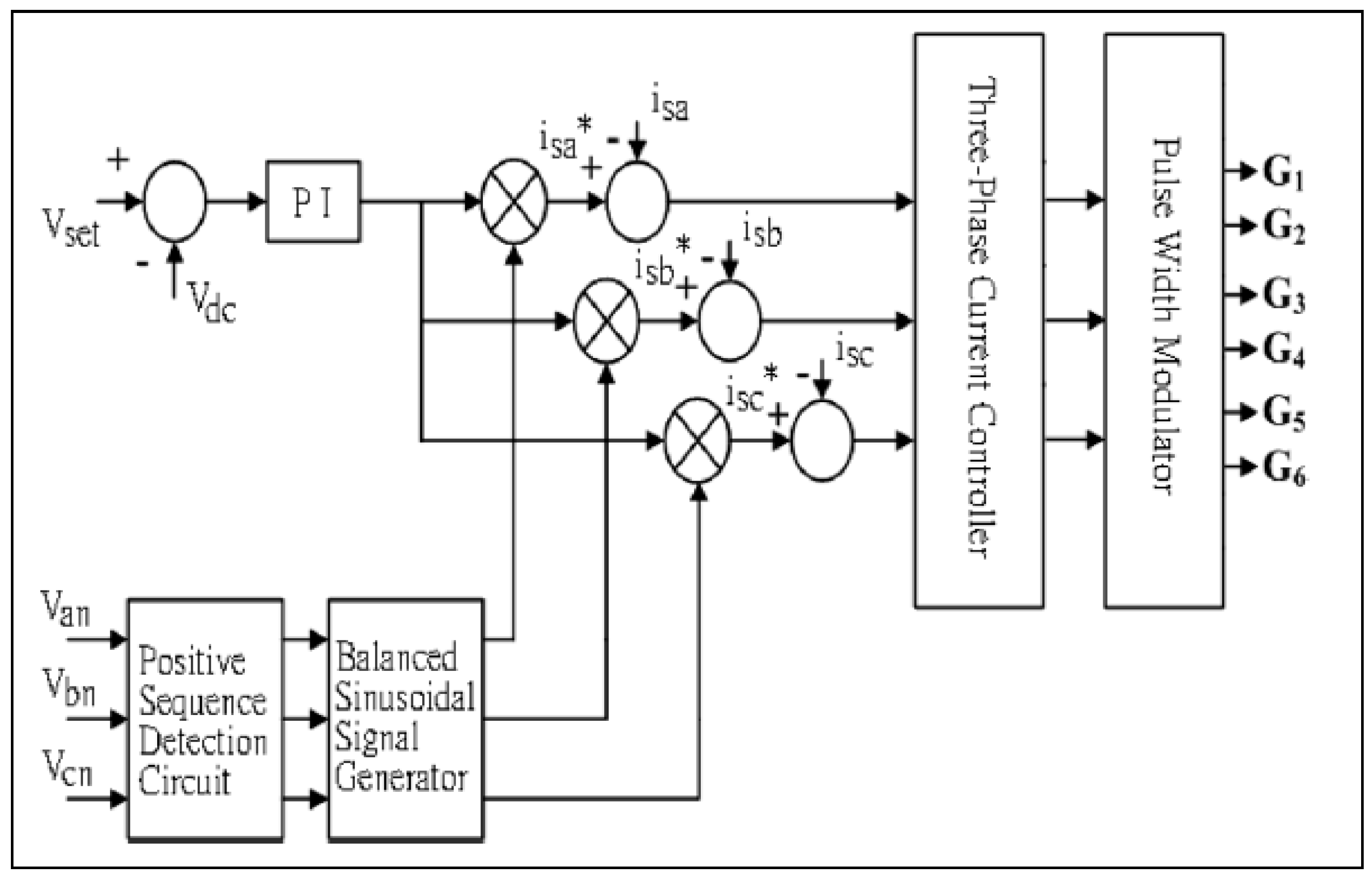
The block diagram of the proposed active power filter is shown in Figure 4. Seen from above, it becomes clear that the control objects are the utility currents and that the reference signals are the desired utility currents. After the control circuit computer reference signals, these signals and the utility currents will be sent to the current control. By this process, the switching signals will be generated for the power electronic circuit installed in the power converter, forcing the utility currents to comply with the reference signals. The reference signals are of three sinusoidal signals whose amplitudes can be controlled. After the voltage of the DC capacitor is detected and subducted from the initial setting voltage, the resulting error will be sent to the P-I controller. Here, the set DC voltage is the desired steady-state value of the DC capacitor voltage. The amplitude of the reference signals will be produced by the P-I controller.
Since the utility voltages are often unstable in the current power distribution system, they must be forwarded to a positive-sequence detection circuit to gain a three-phase balance of the utility currents following the compensation process. With Equation (11) [15], the unstable (or unbalanced) utility voltages can be distinguished as zero-sequence, positive-sequence, and negative-sequence components:
where the components are represented as Vs0, Vs1, and Vs2, respectively, and the operator is defined as:
Following Equation (11), the positive-sequence component can be represented as:
Therefore, two 120° phase shift circuits and a summing circuit have been used to configure the positive-sequence detection circuit. To generate the three-phase balanced sinusoidal signals, the output of the positive-sequence circuit was fed to the balanced sinusoidal signal generator, which contains two 120° phase shift circuits that are able to obtain the b and c signals, and three band-pass filters to screen out the harmonics [13,14,15,16]. The outputs of this signal generator and the P-I controller are then transmitted to multipliers whose products are the desired three-phase utility currents. For this study, the fixed frequency current mode control has been used. Direct detection of the practical utility currents is carried out by the three current sensors, followed by the transmission of both the desired three-phase utility currents and the practical utility currents to the three-phase current controller. Eventually, the output signals generated by the current controller are delivered to the pulse-width modulator for the purpose of generating the driving signals for the power electronic devices embedded in the power converter. If the desired utility currents can be traced by the practical utility currents, the anticipated active power filter performance will be retained.
The three-phase, four-line equation is intended to have three-phase Y connection, and the neutral line is connected to the neutral point. Phase voltage is produced between phases, and line-to-line voltage is produced from the phase and neutral line. Phase voltage is equivalent to the square root of three times the line-to-line voltage on any Y connection.
In apartments or small buildings, since only one same-phase 220 V electricity is supplied to the wall plug, electrical problems are not an issue. Since electricity in the three-phase, four-wire system is directly supplied to large buildings or churches and auditoriums equipped with appliances that need a large amount of electricity, such as air conditioners or elevators, however, there might be a problem regarding electricity.
Most of the electricity we used is 220 V 60 Hz alternating current by binding two strands only as shown in the figure below. Note, however, that ships employ 440 V and 660 V rather than 220 V, and four strands of electric wire are connected and used.
Meanwhile, the electrical problem in sound equipment occurs when 220 V electricity is separated from electricity in the three-phase, four-wire system and used. In other words, three-phase means alternating current wherein each of the three waves whose timing is 120° different is introduced to a different line. If three waves are combined, it produces 440 V electricity; if one of them is used, it produces 220 V electricity.
As presented in the equation, three 220 V AC waves, and even the same 220 V have a totally different waveform from one another. The problem occurs in the sound. If two 220 V waves whose timing is different are forced to come in contact in sound equipment, it may cause zero collision in the internal electricity circuit but produce undesirable failure or noise. Thus, when sound equipment is installed, all equipment, such as musical instruments, microphones, amplifiers, and notebook computers, use the same phase electricity, so they are called “stage electricity”; in principle, electricity should not be supplied from the general wall surface. Most frequently, if the power supply for wireless microphone receiver adapters is put into the electricity in the wall plug, and the phase of power supply on the acoustic mix side where the microphone cable is inserted is different, then equipment malfunction and noise from the wireless microphone will occur. This is because the electricity is different even if the same 220 V electricity has a different phase. The method proposed in this paper has slow speed through a temporary electrical line for the lantern of workers including acoustic speaker electric lines during shipbuilding, but it can establish safe communication.
2.4. Trend of Communication in Smart Home Architecture
The rapid growth of Smart Homes has been forecast regularly over the past decade, and the global communication/information company Cisco System has claimed that Industry 4.0 will be worth US$14.4 trillion within the next ten years. The key to such growth is ‘connectivity’ [17]. Additionally, Gartner Research has forecast that the number of digital devices connected within all worldwide networks will amount to over 26 million units by 2020, rising to 100 billion during the next few years. In addition, Strategy Analytics has predicted that the global IT service providers who provide their services to smart homes will enjoy an average annual growth rate of approximately 24.2%, which will boost the market size from $24 billion in 2015 to $71 billion by 2020 [18]. Meanwhile, Transparency Market Research, a market investigation organization in Albany, New York, has estimated that the market for home automation will grow from roughly $5.3 billion in 2014 to $21.6 in 2020, i.e., an annual average growth rate of 26.3% [19]. Commonly, the sensor nodes of home appliances deployed in a smart homes are controlled and managed through the home gateway [20]. To guarantee the security of smart home automation, such elements as confidentiality, integrity, mutual authentication, and message authentication should be provided, for which the datagram TLS (DTLS) protocol embedded with the necessary encryption modules, including SHA-1, RSA, AES, and HMAC, have been standardized (cf. IETF standardization group) [21].
Regardless of the computing power and the storage capacity of sensor nodes, an appropriate security module should be installed on the mode [22]. Smart home automation refers to the intelligent control system that controls, monitors, and manages a variety of electronic equipment and facilities to achieve the full automation process by utilizing the available network resources in the manner often used for factory or office automation [23,24,25].
Home automation technologies are categorized into framework technologies, wire/wireless home networking technologies, and intellectual home appliance technologies [26,27,28]. Framework technologies are then further divided into intellectual middleware, energy management, home networking, and information appliance technologies [28]. The descriptions of individual technologies are as follows: intellectual middleware technology is a core technology that should be installed on every device that constitutes a home network, including home platforms or home appliances for recommending a smart home automation service [29]. It utilizes the information entered by individuals together with circumstantial information when providing a custom service adjusted or provided at the optimal level in consideration of the concerns and circumstances of each user [30,31].
These days, smart home devices are often integrated with various types of media systems so that they have been re-designed. Automatic reconfiguration through the customized media-device connecting technology, which provides differentiated services for individual users based on the learning process of user preferences and habits, which is essential for current smart homes.
Additionally, energy management technology allows the sharing of profiles concerning electricity consumption information between the systems installed in the smart home network, measures the amount of electricity used in each system, detects wasted electricity, and controls all of them to reduce power consumption [31,32].
Meanwhile, home networking technology is a short-distance (local area) cable/wireless networking technology that provides better connectivity between devices within the home network. It offers a bridging technique for cable networking technologies, such as MoCA, PLC, IEEE1394, and HomePNA, as well as for wireless networking technologies, including Bluetooth, ZigBee, UWB, Wireless1394, and 802.15.4a, even for different networks [33,34,35].
Information appliance technology, which can be embedded in every type of home appliance, controls all home appliances and adjusts and manages the smart home environment automatically, as well as multimedia and IT/ICT environments [34,35,36,37,38].
Using the power line communication system for smart home automation has become an issue and it is being increasingly adopted for smart homes, whereas this system is initially used when building a ship.
3. Design of a Shipboard Outside Communication Network and Its Test Bed Using PLC
Figure 5 shows a diagram of the PLC-based outside communication network system used to manage workers’ safety. The A-zone is a yard-zone where it is difficult and costly to construct communication line(s).
The system is implemented by integrating and converging currently-available wireless technologies. Costs can be reduced if the PLC technology is used.
Figure 6 represents the entire network, which is divided into zones B and C, with the color red indicating their starting point. Zone B has been implemented by SK Telecom; while the proposed system, i.e., the three-phase three-line type of PLC, has been implemented in zone C. The PLC technology applied in this case has been mentioned in the related research section above. However, in zone B, the three-phase four-line type of PLC has been used, with the MCU for the connection.
Figure 7 shows shipbuilding work at a shipyard where the workers pair up to carry out their tasks. However, when they work (for instance, welding) inside the ship, signal attenuation will occur because the steel hull will block the signals and their workplace will become a shadow area. For this reason cables are rarely used so as to avoid such a situation, but efficiency and cost effectiveness are not particularly good. In the shipbuilding yard, enabling communication itself is more important than achieving high communication speed. Ships are built as bulkheads, as shown in the Figure 7.
Thus, we conducted a testbed experiment in which the power line used for the construction equipment (e.g., for welding equipment or lanterns) was drawn to enable power line communication. The reason for the pairing is to avoid the possibility of suffocation. The workers take it in turn so that if one suffocates, the other worker can inform other persons on the outside about the situation. It would be ideal if one of the pair could keep providing information on the condition of his partner, but the communication line would have to be kept open continuously to allow this.
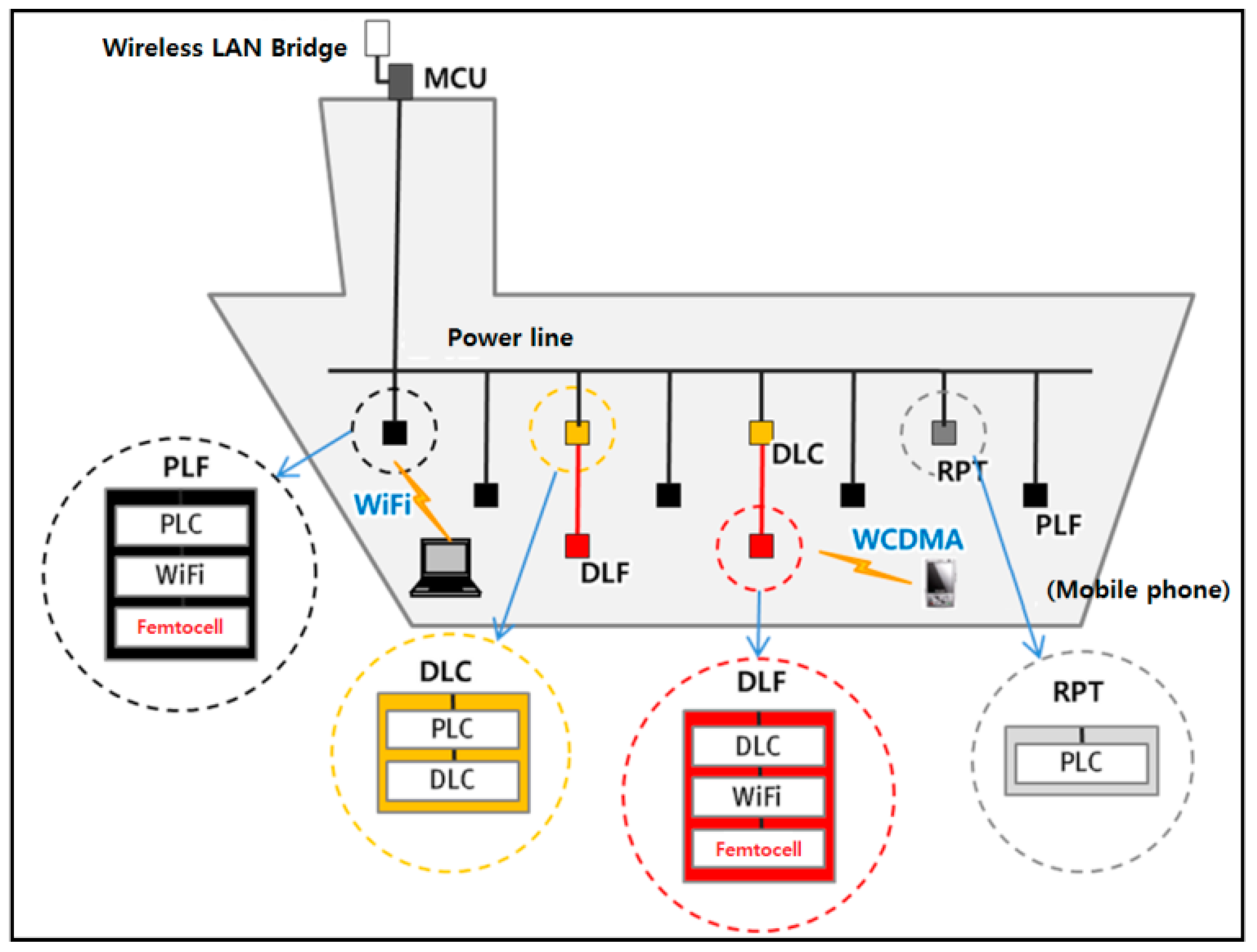
Figure 8 shows the detailed network configuration; and, in an area where the quality of the power line is good, the communication service is provided through the PLF which utilizes the PLC system. Then, for an area that is distant from the ECR, communications will be relayed using the RPT (PLC repeater) and serviced through the PLF. However, as the femtocell was designed and implemented by SK Telecom, we will not discuss it in this article.
3.1. Outside Communication Network Problem Solving Methods
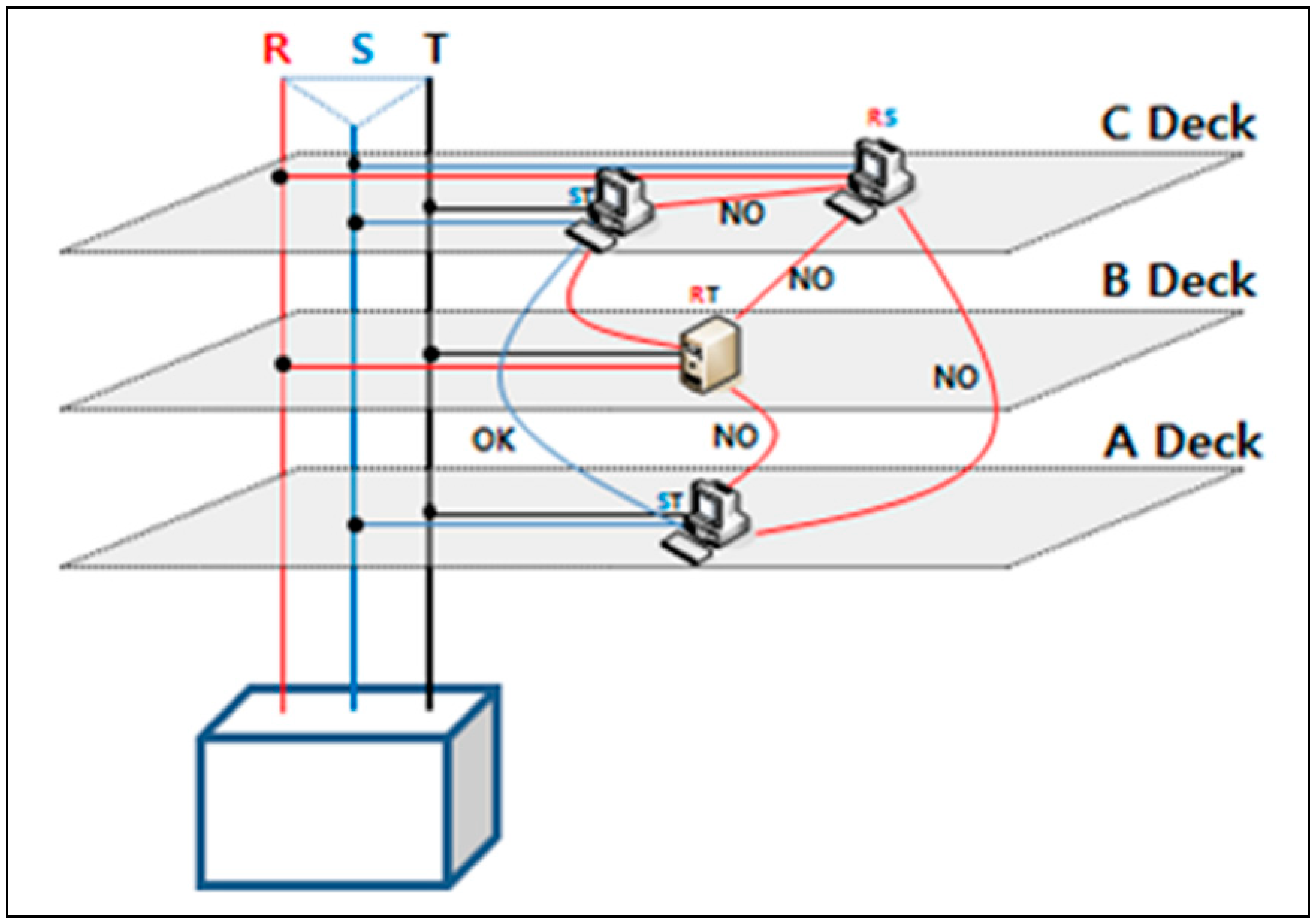
For example, as shown in Figure 9, if the PCs on deck A and deck C use the same ST-phase, network connection will be possible between the PCs, it will be impossible to make a connection when they each have different phase connections, like ST and RS, even when the PCs are located on the same deck, C.
The power line structure of ships differs from that of the land-side as ships operate at sea most of the time, so the structure does not have a common polarity of N, which plays the role of a ground connection.
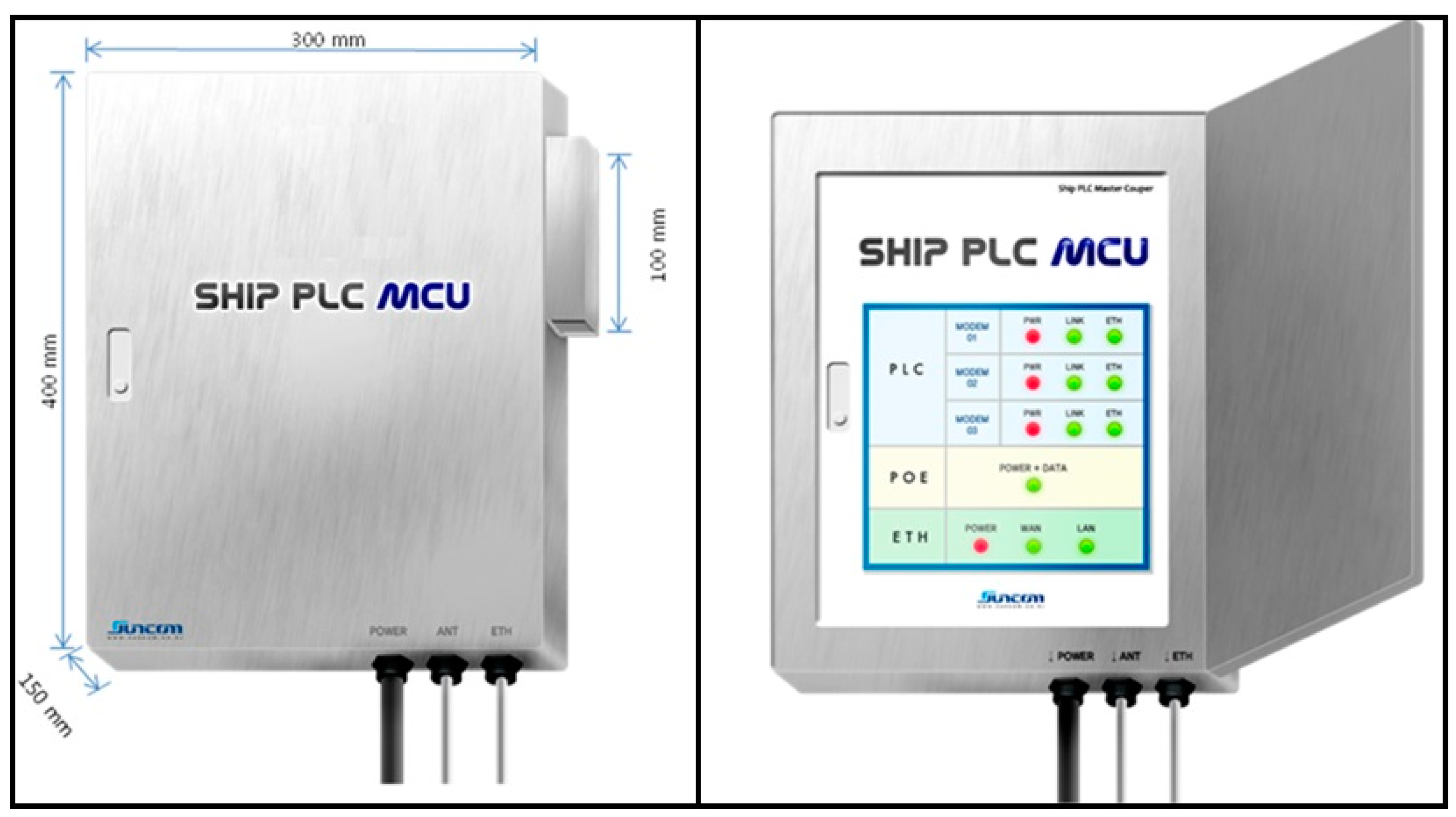
Thus, it was difficult to construct a communication system on a ship with just three phases (R, S, and T). For this reason, we have solved the problem by configuring the system with parallel connections (RS, RT, and ST), as shown in Figure 10. Such a problem with the delta connection method has been solved by coupling the R-, S-, and T-phases at the front part of the transformer where the power is supplied initially, thus enabling successful network connections. Also, Table 1 shows specifications of the MCU. And, Figure 11 shows Prototype of the Ship-PLC MCU [1].
As shown in Figure 12, the PLC master coupler installed in the ship’s main distribution panel (110–440 V) consists of three power lines for communication and three hub chipsets. In these chipsets, a single line is connected to each R/S/T phase.
The structure is that of the main device, which allows access with the end point user. The PLC-chipset connected to each R/S/T phase is then linked to a hub module, such that each phase will be included in the whole network of end point users in different locations, connected online. Figure 13 shows an algorithm of the PLC master coupler PCB.
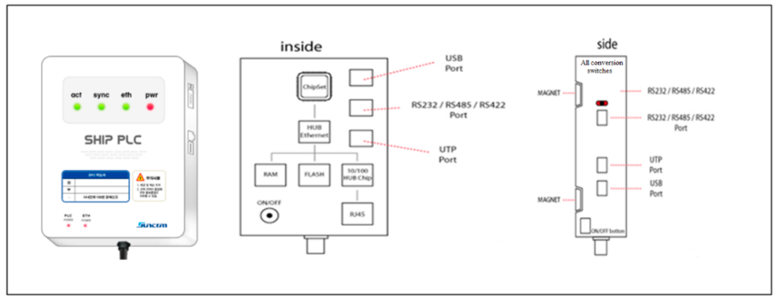
Figure 14 describes the PLC slave modem. This device plays the role of transmitting the monitoring data of a certain device that needs to be monitored consistently by interfacing with that device and sending the data to the data acquisition device through the master coupler using the shipboard power line.
3.2. PLC Repeater
The PLC repeater, i.e., the Ship Power Line Communication Repeater, in full, is installed at the central point to secure the quality of the power line when it is impossible to secure the quality of data communication fully because the targeted area to which the femtocell service will be applied is distant from the main power supply. The specifications of the product are as shown in Table 2.
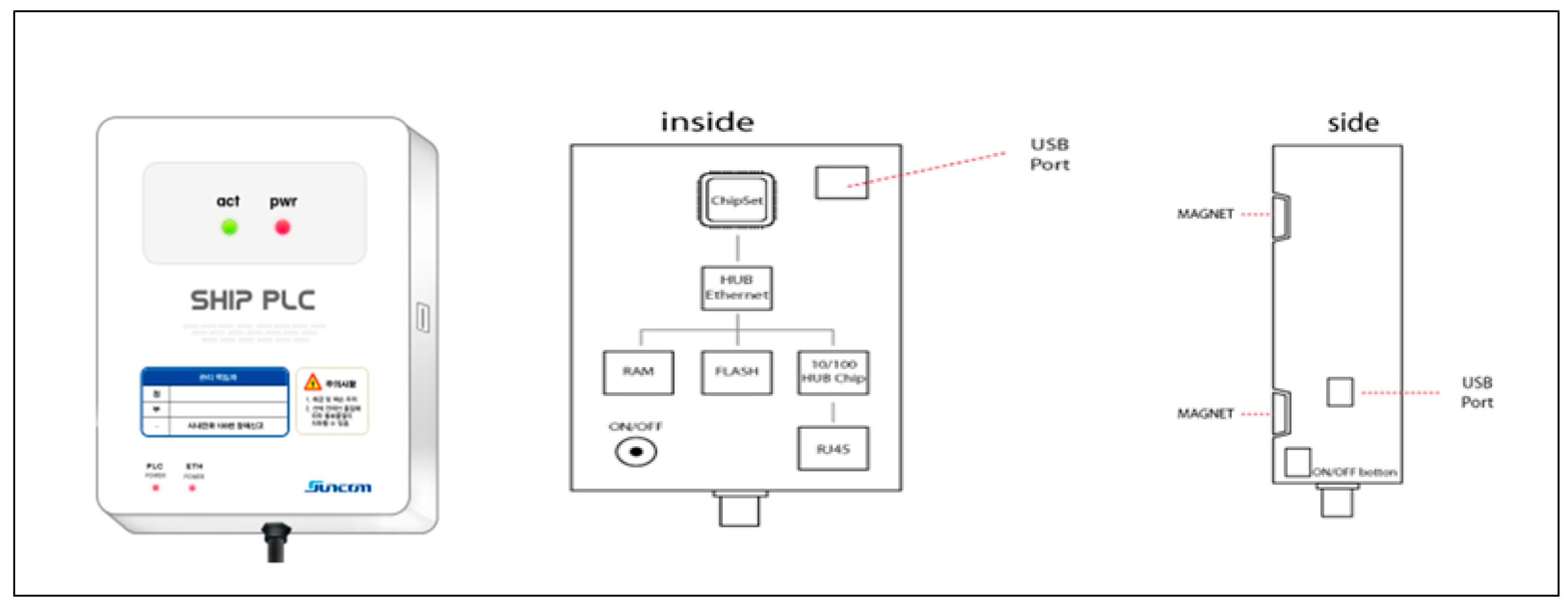
Figure 15 is a diagram of the PLC repeater, which plays the role of a signal amplification device in order to prevent a decline of the transmission speed due to signal attenuation and noise pick-ups over the long distance between the slave modem and the master coupler.
To maintain optimal performance and reliability, these devices undergo qualification tests conducted by an authorized inspection agency of the Republic of Korea, such as KOLAS, etc., where on-site verification tests using a quantitative measurement method are carried out.
3.3. Data Link and FemtoCell
Data Link and FemtoCell (DLF), i.e., the Ship-Data Link Communication and Femtocell Slave Unit, in full, which is embedded with femtocell, WiFi AP, and a DLC modem, transmits the data generated through the femtocell and WiFi AP using the data link. Here, we skip the description of the femtocell for the same reason mentioned above. Its specifications are as shown in Table 3.
4. Performance Evaluation
The shipboard PLC modem technology developed for this study could ultimately be used as a safety management system for shipbuilding workers in addition to its application to operating ships. Since most ships are built by assembling pre-built blocks, the workers who carry out the welding and grinding works for each block are constantly exposed to safety accidents as their radios or mobile phones often miss communication signals due to the signal attenuation blocked by the steel walls, making it impossible to call for outside help.
SUNCOM Co. has experience in resolving such communication problems by establishing a connection between a small-scale 3G communication base station of a certain mobile telecommunication company and the shipboard PLC modem (March 2011, Hyundai Mipo shipyard) [38]. In this study, two performance analyses of a ship currently under construction were conducted with our modem (200 Mbps).
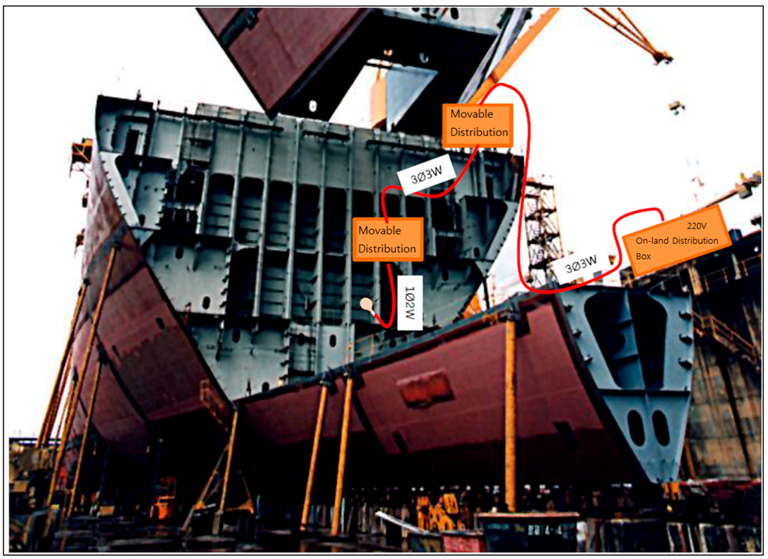
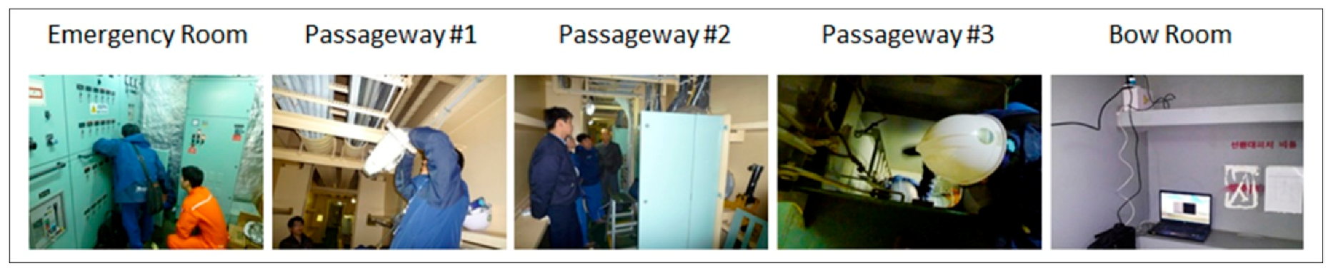
The power line communication is installed directly on the electric lines in the ship. We conducted an experiment, and the installation process is shown in Figure 16, which illustrates the system of ship power line communication (PLC) to build a network inside the ship using the power line through which electricity is supplied to the ship. It is a system that enables communication when construction is performed at the ship’s bulkhead. Using this system, a network can be rapidly built in a short period of time economically when a new network is configured.
Since the power lines furcate in each section to supply power, we applied the PLC repeater for each section (i.e., passage #1, #2, and #3), and by using the PLC we constructed a network between the bridge and the bow room, followed by the test. Our goal was to apply the network to the cargo hall.
We first installed a PLC master coupler in the 200 V emergency breaker panel of the emergency room located on the upper deck. Second, the PLC modem was installed in the bow room and, third, a PLC repeater modem was installed at 100 m on the passageway. Fourth, the PLC repeater modems were installed at 2/5 and 4/5 points of the passageway. Fifth, the passageway 220 V emergency breaker PLC repeater was installed and, finally, we confirmed the network establishment after installing the PLC repeater on the rotary switch located at the entrance of bow room.
The ship PLC can provide not only a ship area utilizing a wired and wireless communication network combining communication technologies, such as Wi-Fi, but also a network infrastructure that can monitor a number of ship facilities under the ship’s deck.
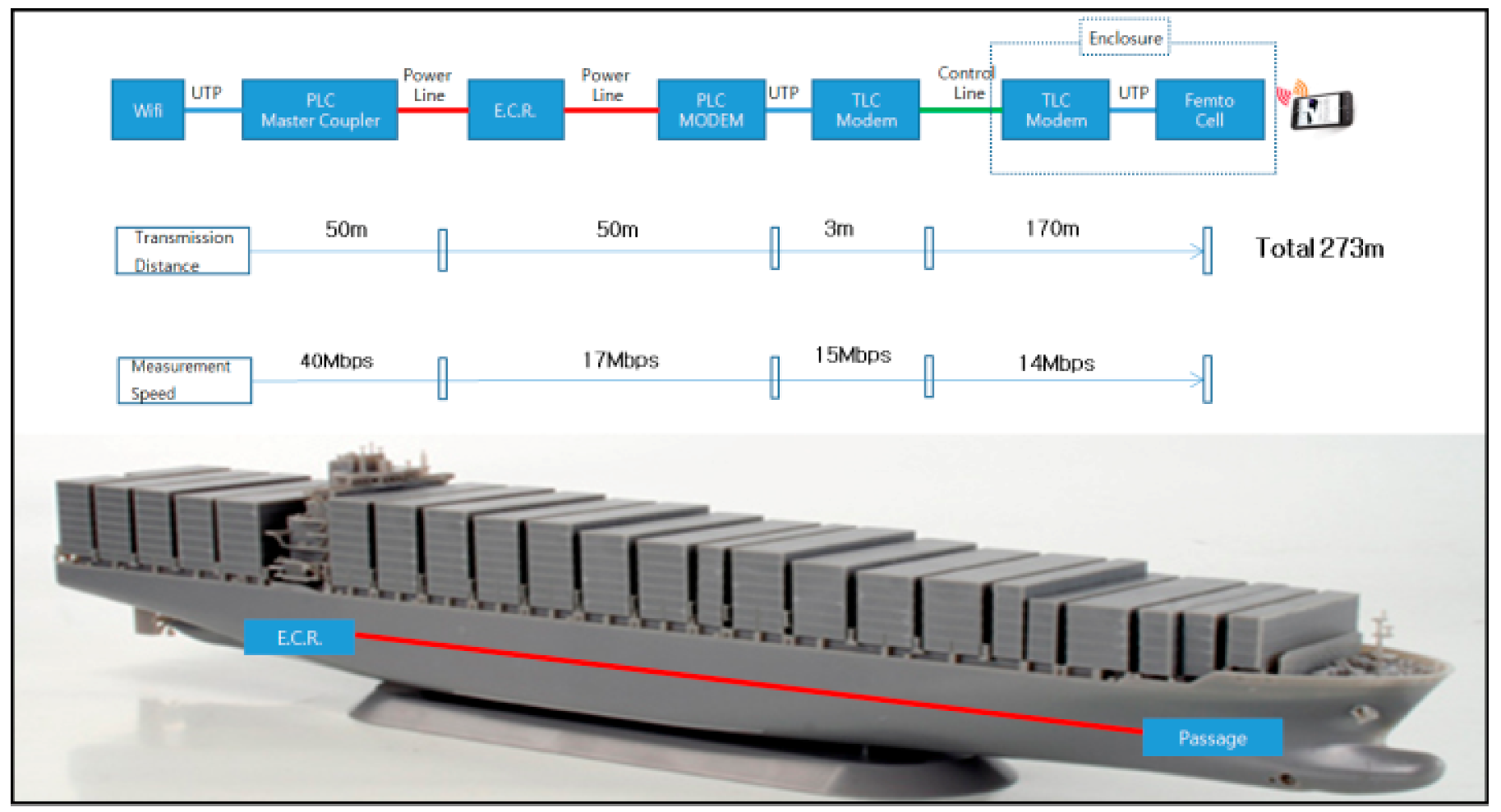
The first analysis involved a voice quality test in which the PLC-based TCP/IP communication performance of a drillship owned by Hyundai Heavy Industries was measured using the 220 V onboard power generator. The result was satisfactory, as shown in Figure 17. Note that “satisfactory” as used in this paper is defined as a constant usable communication speed without any interruption of communication, so it is suitable for safety-first systems. In other words, the communication speed is slow, but the communication success rate is 100%.
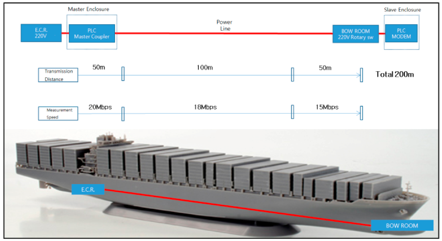
The second performance analysis was conducted on a containership of the same company and with the same generator. The quality of the data was also satisfactory, as shown in Figure 18.
In this study, a speed of 200 Mbps was applied in the lab test, although the actual highest speed obtained ranged from 15 Mbps to 18 Mbps on average. This result was somewhat different to the expected speed of 24 Mbps, but we believe that this is due to signal attenuation on the power line. We will try to correct the situation but, yet, the problem of Internet disconnection will not occur in the system, so we believe that there is still a good business opportunity.
Many people in IT-advanced countries have changed their Internet providers on the assumption that that they would be better served by companies that provide a 100 Mbps Internet speed, but the actual speeds they experienced were somewhat disappointing, ranging from 12 Mbps to 50 Mbps at best. This was very different from the advertisements they saw or the terms of the contract sheets they received.
One such term mentioned that the customers would be able to enjoy a data transmission speed of near 100 Mbps. This might be true, but what they should be aware of is the technical term ‘bit’, which usually refers to a binary digit. The ‘bit’ is the lowest unit used in describing a PC’s capacity or processing power; and it can also be used to indicate the size of a file. By contrast, users are usually familiar with the unit ‘byte’. This unit is used to indicate the amount of information or data as these cannot be adequately expressed with bits, the binary system using only 0 and 1. One byte is equivalent to eight bits, so that 100 bits are equal to 12.5 bytes. The use of “bits” was not inconvenient in expressing capacity in the past, but as the volume of data has increased over time, they were replaced by “bytes”. Nevertheless, ‘bits’ are still used in the field of communication to measure the communication speed (bps: bits per second). Such usages cause much confusion among customers. It might be better if such a mixed usage is avoided altogether and replaced with some kind of new standardized unit, or by indicating both units for customers’ understanding [39].
The total number of ships SUNCOM Co. installed the PLC system from 2007 to 2015 was 39 and the average cost involved in the system construction was approx. US$8000 per ship. For the 39 ships, the distances for the system construction ranged from a minimum of 170 m to 200 m maximum, showing a total average distance of roughly 185 m.
5. Comparison with Other System
The proposed system, which uses a femtocell together with the PLC technology to cover shadow areas, can be compared with the shipboard acoustic communication technology developed by Professor Jin-Ho Bae and his team [40] (JNU: Jeju National University), who have successfully established communications across a ship covering the shadow areas.
Although it was believed that radio communications are rarely possible in iron-structured (bulkheads) ships, his team was able to establish communications covering a distance of 100 m in a ship and to secure the patent rights for its source technology through the research project titled “Ultrasonic Communication Technology for Shipboard Communication Network Construction” [40].
The experiments conducted for this project used only a single acoustic transducer (10 Kbps) to cover a distance of 100 m under a non-optimized environment. As this is similar to just using a set of two-way radios, they are planning to optimize the system by using multiple transducers to increase the distance and the performance level. Daewoo Shipbuilding and Marine Engineering Co., Ltd at ROK., which occasionally experiences toxic gas-related accidents in areas blocked by bulkheads, was able to verify the feasibility of the team’s technology.
JNU claims that they achieved more than originally expected amid a situation in which it was not easy to obtain a successful result using dynamics and electrical/electronic acoustic knowledge, all of which are radically different in nature. They also stated that the technology for transmitting sound waves through iron structures has been used to detect defects up until now, but that using it for communications would create new opportunities for integrating shipbuilding and IT technologies, and that synergistic effects could be obtained through cooperation with experts in communications, signal processing, and acoustics. The major difference between this technology and the proposed technology is that the former uses ultrasonic waves instead of a power line (three-phase three-line) for communication.
We hope that our proposal will contribute to an improved work environment by reducing fatal accidents in the shadow areas within dockyards.
6. Discussion
Small and large-scale industrial disasters involving casualties have constantly occurred in shipbuilding yards in Korea up until now. According to the Ministry of Employment and Labor, the average industry accident rate of all industries was 0.49% last year. The average industry accident rate in the shipbuilding industry during the same period was 0.83%, which was twice the average rate. The death rate in industrial accidents per 10,000 workers in the shipbuilding industry stood at 1.39%, which is significantly higher than the mean death rate (0.96%) of all industries. More than 40% of deaths were due to accidents caused by suffocation or narrowness during bulkhead building.
According to the accident case in Hyundai Heavy Industries Co., Ltd at ROK., mobile phones were not serviced inside a large ship whose area was the size of four football stadiums due to poor reception between workers who worked on building a ship for about a year, so instructions about work could not be delivered to colleagues quickly. In addition, work concentration was adversely affected since workers had to go outside of the ship for reports to be delivered to the office. Note, however, that mobile phones are now serviced in major working spaces inside the ship using the PLC proposed in this study and SK Telecom femtocells, contributing to the significant increase in work efficiency and safety. Hyundai Heavy Industries Co., Ltd. in Korea proved the efficiency of the specialized wireless Internet phone inside the ship during the shipbuilding process after constructing an environment wherein the phone above can be used, for the first time, by combining wireless LAN and PLC.
In other words, specialized wireless Internet phones were used using the PLC technology in areas where mobile communication services are not provided. Note, however, that general mobile phones can be used by applying the PLC proposed in this study and femtocell technology of SK Telecom. Accordingly, a constant contact system in response to emergency situations and improvements in work productivity inside the ship can be achieved, and more efficient and safer work environments can be provided.
SK Telecom Co., Ltd and SUNCOM Co., Ltd have conducted on-site tests of the solution during the shipbuilding in Hyundai Heavy Industries Co., Ltd., and the solution was adopted after completing the validity test. The solution adopted this time can provide mobile communication services inside the ship during shipbuilding, thereby enabling rapid processing of work reports and instructions, as well as quick responses to disaster occurrence, contributing to improvements in work efficiency in shipbuilding yards and ensuring workers’ safety.
7. Conclusions and Future Work
The testbed experiments show that the proposed technology has the potential to improve labor productivity by reducing the possibility of accidents and to contribute to the welfare of construction workers at construction sites. The main object of developing such a technology is to enable uninterrupted and smooth communications in wide open spaces with minimal costs so as to avoid industrial accidents. This platform technology could be applied to many other systems that are likely to be developed in the future. Its cost-effectiveness and superior communication distance when compared with UTP cable-based communication systems will no doubt bring more profits to ship- or plant-building companies as they will be able to avoid installing separate lines for communications and power transmissions.
Considering the depreciation cost calculation obtained from the testbed experiments, a cost saving of approximately 85% (maximum) can be expected once the PLC-based communication system is adopted. The estimated cost of constructing the system is about 15 million Korean won, which is just half of the amount that would be needed to construct two separate lines for both power and communications (as of November 2017). The calculation was based on the assumption that the cost of building a ship would be around 150 billion Korean won. Additionally, our qualitative analysis has proven the positive economic effects for the shipbuilding industry.
Other involved secondary technologies are not described in this study, but will be introduced later on in an extended article after the patent registration has been completed. We hope this study will contribute to improving the working environment by reducing accidents at construction sites, especially in shadow areas.
Network communication technology, which plays the role of a nerve system on a vessel, is being developed continuously, laying the foundations for next-generation intelligent vessels. Vessels consisting of more than 30,000 parts can be considered as an integral body of engineering and electronic science and IT technology. The development of a shipboard network (or a ship area network) communication technology will lead to a more advanced sensor-based monitoring technology, and such a technology will be able to perform the work of many trained crew members on newly-built cutting-edge vessels. However, the technology proposed in this study can not only be applied to new ships, but also to old ships that are being operated under poor environments and which require safety improvements. Actually, over 40 ships have already adopted this technology, and their crews are very satisfied with them.
Author Contributions
Conceptualization: J.-H.H. and T.K.; Data curation: J.-H.H. and K.S.; Formal analysis: J.-H.H.; Funding acquisition: J.-H.H.; Investigation: J.-H.H.; Methodology: T.K.; Project administration: J.-H.H.; Software: T.K.; Validation: J.-H.H. and K.S.; Writing—original draft: J.-H.H.; Writing—review and editing: K.S.
Acknowledgments
The first draft of this article was presented in 2016 at the International Conference on Ubiquitous Information Management and Communication, ACM IMCOM 2016, Da Nang, Vietnam [1]. The three-phase three-line method was used and this case will be introduced in the scheduled extended journal article after presenting the details at 2016 ACM IMCOM conference [1]. We hope this study will contribute in improving the working environment by reducing the accidents at the construction sites, especially in the shadow area. This work was supported by the National Research Foundation of Korea(NRF) grant funded by the Korea government(MSIT) (No.2017R1C1B5077157).
Conflicts of Interest
The authors declare no conflict of interest.
Appendix A
In this paper, a speed of 200 Mbps was applied for the lab test, but the actual highest speed obtained ranged from 15 Mbps to 18 Mbps on average. The result was quite contrary to the expected speed of 24 Mbps, and we believe that this is due to signal attenuation on the power line. We will try to correct the situation but, yet, the problem of Internet disconnection will not occur in the system so we expect that there remains a good business opportunity. SUNCOM Co., Ltd., established by an industry-university collaboration project, is proceeding with a business that utilizes PLC technology in the Republic of Korea and has already developed 200–500 Mbps-level PLC-based products. Additionally, in the preceding research [10] and business project, they have carried out the PLC-based internet constructions on existing ships on more than 40 occasions.
References
- Huh, J.; Koh, T.; Seo, K. Design of a Shipboard outside Communication Network and the Test Bed Using PLC: For the Workers’ Safety Management During Ship-Building process. In Proceedings of the 10th International Conference on Ubiquitous Information Management and Communication, ACM IMCOM 2016, Da Nang, Vietnam, 4–6 January 2016; p. 43. [Google Scholar]
- Barmada, S.; Bellanti, L.; Raugi, M.; Tucci, M. Analysis of Power-Line Communication Channels in Ships. IEEE Trans. Veh. Technol. Vol. 2010, 59, 3161–3170. [Google Scholar] [CrossRef]
- Antoniali, M.; Tonello, A.M.; Lenardon, M.; Qualizza, A. Measurements and Analysis of PLC Channels in a Cruise Ship. In Proceedings of the 2011 IEEE International Symposium on Power Line Communications and Its Applications, Udine, Italy, 3–6 April 2011; pp. 102–107. [Google Scholar]
- Nishioka, J.; Tsuzuki, S.; Yoshida, M.; Kawasaki, H.; Shinpo, T.; Yamada, Y. Characteristics of 440 V Power-Line Channels in Container Ships. In Proceedings of the IEEE International Symposium on Power Line Communications and Its Applications, Dresden, Germany, 29 March–1 April 2009; pp. 217–222. [Google Scholar]
- Tsuzuki, S.; Yoshida, M.; Yamada, Y.; Murai, K.; Kawasaki, H.; Matsuyama, K.; Shinpo, T.; Saito, Y.; Takaoka, S. Channel Characteristic Comparison of Armored Shipboard Cable and Unarmored one. In Proceedings of the 2008 IEEE International Symposium on Power Line Communications and Its Applications, Jeju Island, Korea, 2–4 April 2008; pp. 7–12. [Google Scholar]
- Tsuzuki, S.; Yoshida, M.; Yamada, Y.; Kawasaki, H.; Murai, K.; Matsuyama, K.; Suzuki, M. Characteristics of Power-Line Channels in Cargo Ships. In Proceedings of the 2007 IEEE International Symposium on Power Line Communications and Its Applications, Pisa, Italy, 26–28 March 2007; pp. 324–329. [Google Scholar]
- Huh, J.-H.; Seo, K. PLC-Based Smart grid Home Network System Design and Implementation using OPNET Simulation. J. Multimedia Inf. Syst. 2014, 1, 111–118. [Google Scholar]
- Wolkerstorfer, M.; Statovci, D.; Nordström, T. Enabling greener DSL access networks by their stabilization with artificial noise and SNR margin. Clust. Comput. 2013, 16, 407–419. [Google Scholar] [CrossRef]
- Yan, L. Power Line Carrier Technology Used in the Ship Communication System. Electr. Electron. Eng. 2010, 3, 21. [Google Scholar]
- Huh, J.-H.; Koh, T.; Seo, K. NMEA2000 Ship Area Network Design and Test Bed Experiment using Power Line Communication with the 3-Phase 3-Line Delta Connection Method. Int. J. Appl. Eng. Res. Res. India Publ. 2015, 10, 27789–27797. [Google Scholar]
- Huh, J.-H.; Seo, K. Hybrid Advanced Metering Infrastructure Design for Micro Grid Using the Game Theory Model. Int. J. Softw. Eng. Its Appl. 2015, 9, 257–268. [Google Scholar] [CrossRef]
- Huh, J.H.; Koh, T.; Seo, K. NMEA2000 ship area network (SAN) design and test bed using power line communication (PLC) with the 3-phase 3-line delta connection method. Adv. Sci. Technol. Lett. 2015, 94, 57–63. [Google Scholar]
- Wu, J.C.; Jou, H.L. Simplified control method for the single-phase active power filter. Proc. Inst. Electr. Eng. 1996, 143, 219–224. [Google Scholar] [CrossRef]
- Le Roux, A.D.; Toit, J.A.D.; Enslin, J.H.R. Integrated active rectifier and power quality compensator with reduced current measurement. IEEE Trans. Electron. 1999, 46, 504–511. [Google Scholar] [CrossRef]
- Glover, J.D.; Sarma, M.S. Power System Analysis and Design, 3rd ed.; Brooks/Cole Is an Imprint of the Wadsworth Group; Wadsworth Group: Denver, CO, USA, 2002. [Google Scholar]
- Jou, H.-L.; Wu, K.D.; Wu, J.-C.; Chiang, W.-J. A Three-Phase Four-Wire Power Filter Comprising a Three-Phase Three-Wire Active Power Filter and a Zig–Zag Transformer. IEEE Trans. Power Electron. 2008, 23, 252–259. [Google Scholar] [CrossRef]
- Bayram, I.S.; Papapanagiotou, I. A survey on communication technologies and requirements for internet of electric vehicles. EURASIP J. Wirel. Commun. Netw. 2014, 2014, 223. [Google Scholar] [CrossRef] [Green Version]
- Pittolo, A.; De Piante, M.; Versolatto, F.; Tonello, A.M. In-vehicle power line communication: Differences and similarities among the in-car and the in-ship scenarios. IEEE Veh. Technol. Mag. 2016, 11, 43–51. [Google Scholar] [CrossRef]
- Paul, D.; Peterson, K.; Chavdarian, P.R. Designing cold ironing power systems: Electrical safety during ship berthing. IEEE Ind. Appl. Mag. 2014, 20, 24–32. [Google Scholar] [CrossRef]
- Zhang, W.; Liu, Z.; Wang, M.; Yang, X. Research status and development trend of smart grid. Power Syst. Technol. 2009, 13, 1–11. [Google Scholar]
- Kang, J.; Kim, J. Secure HDFS design using group key management system. J. Internet Technol. 2015, 18, 729–737. [Google Scholar]
- Zhu, Q.; Wang, R.; Chen, Q.; Liu, Y.; Qin, W. IoT gateway: Bridgingwireless sensor networks into internet of things. In Proceedings of the 2010 IEEE/IFIP 8th International Conference on Embedded and Ubiquitous Computing (EUC), Hong Kong, China, 11–13 December 2010; IEEE: Piscataway, NJ, USA, 2010. [Google Scholar]
- Reichherzer, T.; Satterfield, S.; Belitsos, J.; Chudzynski, J.; Watson, L. An agent-based architecture for sensor data collection and reasoning in smart home environments for independent living. In Proceedings of the Canadian Conference on Artificial Intelligence, Victoria, BC, Canada, 31 May–3 June 2016; Springer: Berlin, Germany, 2016. [Google Scholar]
- Deligiannidis, L.; Arabnia, H.R. Emerging Trends in Image Processing, Computer Vision and Pattern Recognition; Morgan Kaufmann: Burlington, MA, USA, 2014. [Google Scholar]
- Bakkali, M.; Mascarenas, C.; de la Campa, F.S.; Martin, C.; Abad, F.J.; Barea, M.; Valverde, J.M.; Valencia, J.; Chover, J.E. Feasibility study of advancing and sitting up power line communication (PLC) system under environment of electromagnetic compatibility (EMC) into the ships. In Proceedings of the 9th International Conference on Electrical Power Quality and Utilisation, EPQU 2007, Barcelona, Spain, 9–11 October 2007; IEEE: Piscataway, NJ, USA, 2007; pp. 1–5. [Google Scholar]
- Valtchev, D.; Frankov, I. Service gateway architecture for a smart home. IEEE Commun. Mag. 2002, 40, 126–132. [Google Scholar] [CrossRef]
- Dahane, A.; Berrached, N.-E.; Loukil, A. A virtual laboratory to practice mobile wireless sensor networks: A case study on energy efficient and safe weighted clustering algorithm. J. Inf. Process. Syst. 2015, 11, 205–228. [Google Scholar]
- Barmada, S.; Raugi, M.; Tucci, M.; Tao, Z. Analysis of time-varying properties of power line communication channels in ships. In Proceedings of the 2011 IEEE International Symposium on Power Line Communications and Its Applications (ISPLC), Udine, Italy, 3–6 April 2011; IEEE: Piscataway, NJ, USA, 2011; pp. 72–77. [Google Scholar]
- Park, J.; Shin, S.; Kang, N. Mutual authentication and key agreement scheme between lightweight devices in internet of things. J. Korean Inst. Commun. Inf. Sci. 2013, 38, 707–714. [Google Scholar] [CrossRef]
- Huh, J.-H.; Je, S.-M.; Seo, K. Design and configuration of avoidance technique for worst situation in zigbee communications using OPNET. In Proceedings of the 7th International Conferences on Information Science and Applications 2016, Ho Chi Minh, Vietnam, 15–18 February 2016; pp. 331–336. [Google Scholar]
- Granjal, J.; Monteiro, E.; Silva, J.S. Security in the integration of low-power wireless sensor networks with the internet: A survey. Ad Hoc Netw. 2015, 24, 264–287. [Google Scholar] [CrossRef]
- Craciunescu, R.; Halunga, S.; Fratu, O. Wireless ZigBee home automation system. In Advanced Topics in Optoelectronics, Microelectronics, and Nanotechnologies; International Society for Optics and Photonics: Bellingham, WA, USA, 2015. [Google Scholar]
- Pandey, M.; Babu, M.R.; Manasa, J.; Avinash, K. Mobile based home automation and security system. Indian J. Sci. Technol. 2015, 8, 12. [Google Scholar] [CrossRef]
- Papageorgiou, A.; Bifulco, R.; Kovacs, E.; Kolbe, H.-J. Dynamic M2M device attachment and redirection in virtual home gateway environments. In Proceedings of the 2016 IEEE International Conference on Communications (ICC), Kuala Lumpur, Malaysia, 22–27 May 2016; IEEE: Piscataway, NJ, USA, 2016. [Google Scholar]
- Huh, J.-H.; Seo, K. An Indoor Location-Based Control System Using Bluetooth Beacons for IoT Systems. Sensors 2017, 17, 2917. [Google Scholar] [CrossRef] [PubMed]
- Huh, J.-H. Big Data Analysis for Personalized Health Activities: Machine Learning Processing for Automatic Keyword Extraction Approach. Symmetry 2018, 10, 93. [Google Scholar] [CrossRef]
- Sinha, A.; Lobiyal, D.K. Performance evaluation of data aggregation for cluster-based wireless sensor network. In Human-Centric Computing and Information Sciences; Springer: Berlin/Heidelberg, Germany, 2013; Volume 3, pp. 1–17. [Google Scholar]
- The World’s Best Shipyard, the Field Communication Environment is Also the Best. Available online: http://www.the-pr.co.kr/news/articleView.html?idxno=2166 (accessed on 26 March 2018). (In Korean).
- Huh, J.-H.; Koh, T.; Seo, K. A Design of Foundation Technology for PLC-based Smart-grave (Tumulus) System. J. Korea Multimedia Soc. 2015, 18, 1319–1331. [Google Scholar] [CrossRef]
- Hull Sound Communication Technology Success. Available online: http://www.etnews.com/201212070339 (accessed on 26 March 2018). (In Korean).
Figure 1.
Three-phase four-wire Y-connection (land-use power line structure).
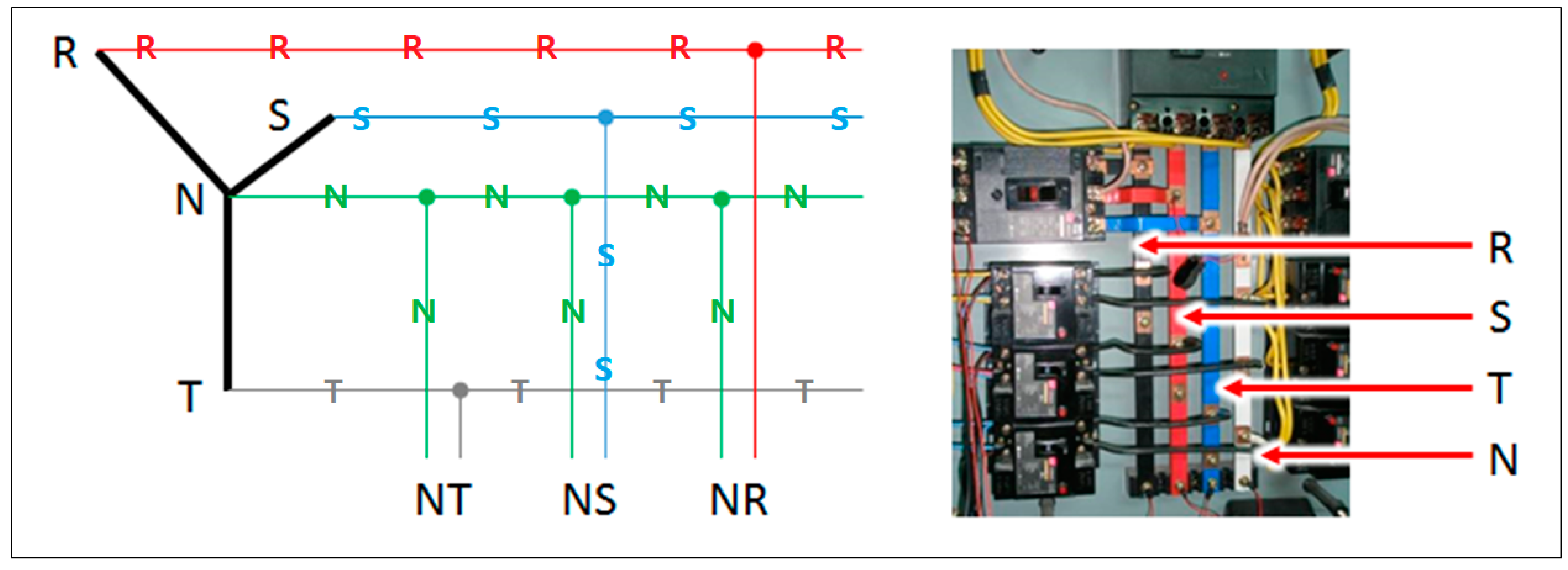
Figure 2.
Three-phase three-wire delta connection (shipboard power line structure).
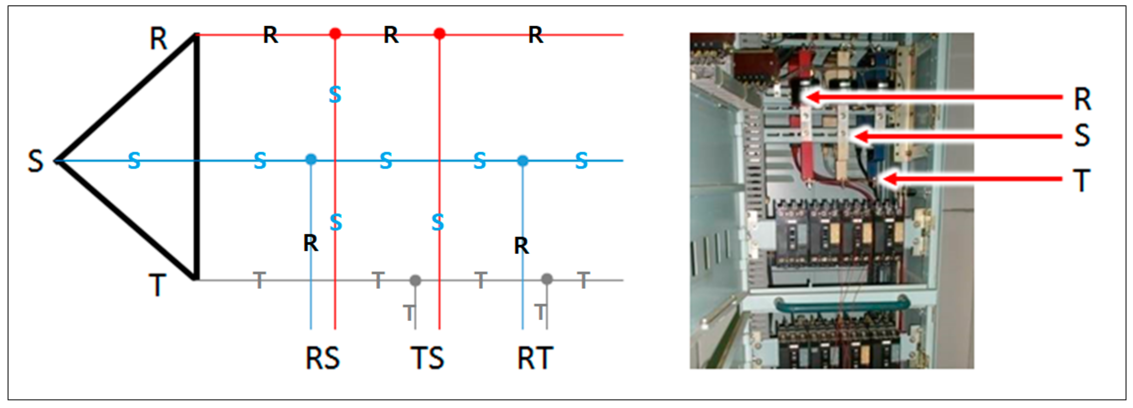
Figure 3.
Ship PLC and its application.
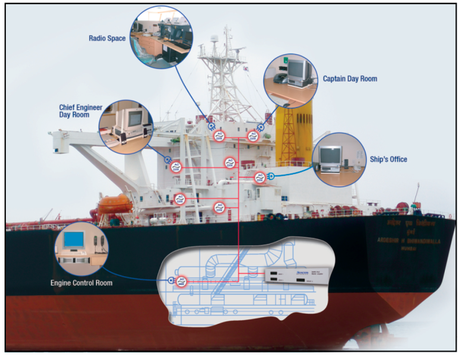
Figure 4.
Block diagram of the proposed three-phase three-line active power filter.

Figure 5.
Design of the outside communication network using PLC.
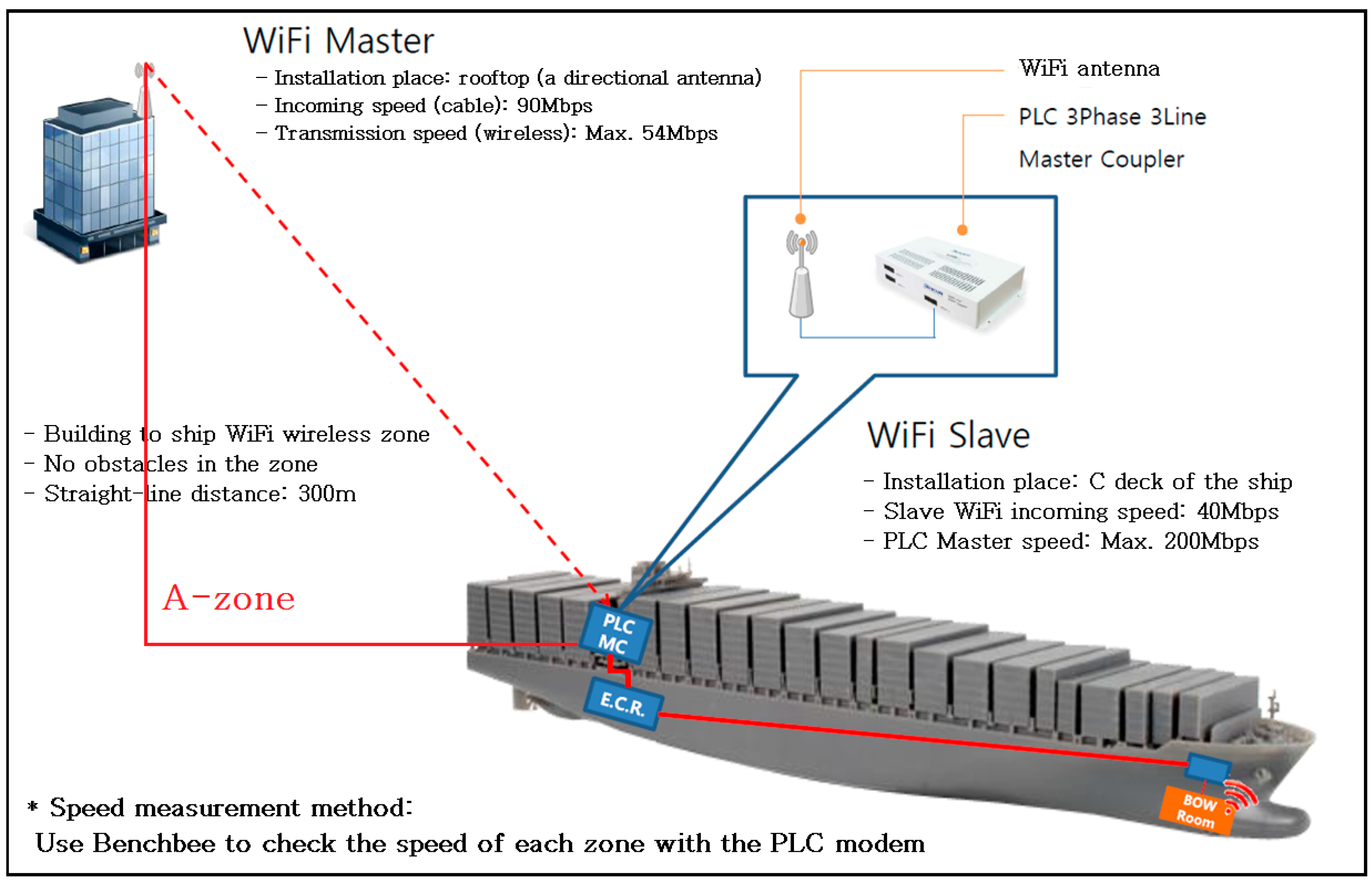
Figure 6.
Configuration of the entire network.
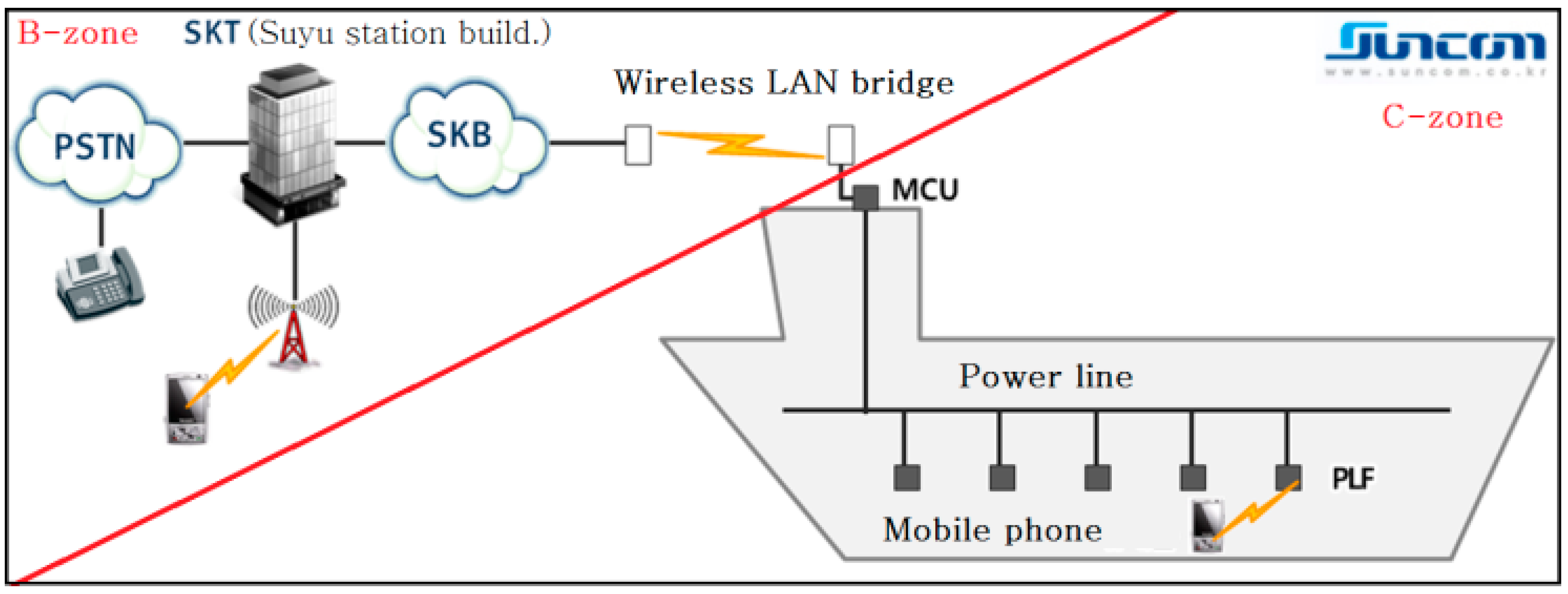
Figure 7.
Shipbuilding at the shipyard.

Figure 8.
Detailed network configuration.

Figure 9.
Outside communication network problem.

Figure 10.
Proposed problem solving method.
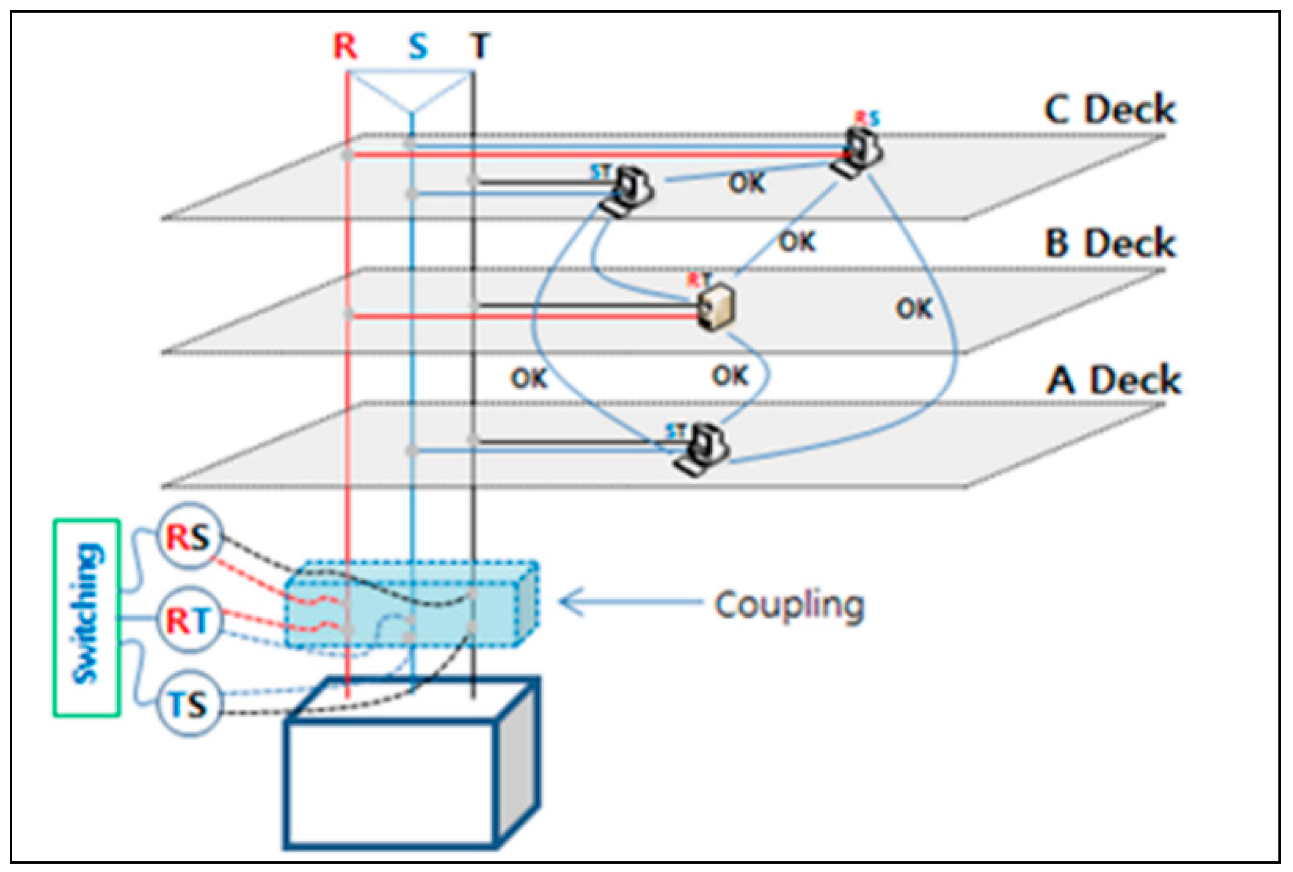
Figure 11.
Prototype of the Ship-PLC MCU.

Figure 12.
PLC master coupler.
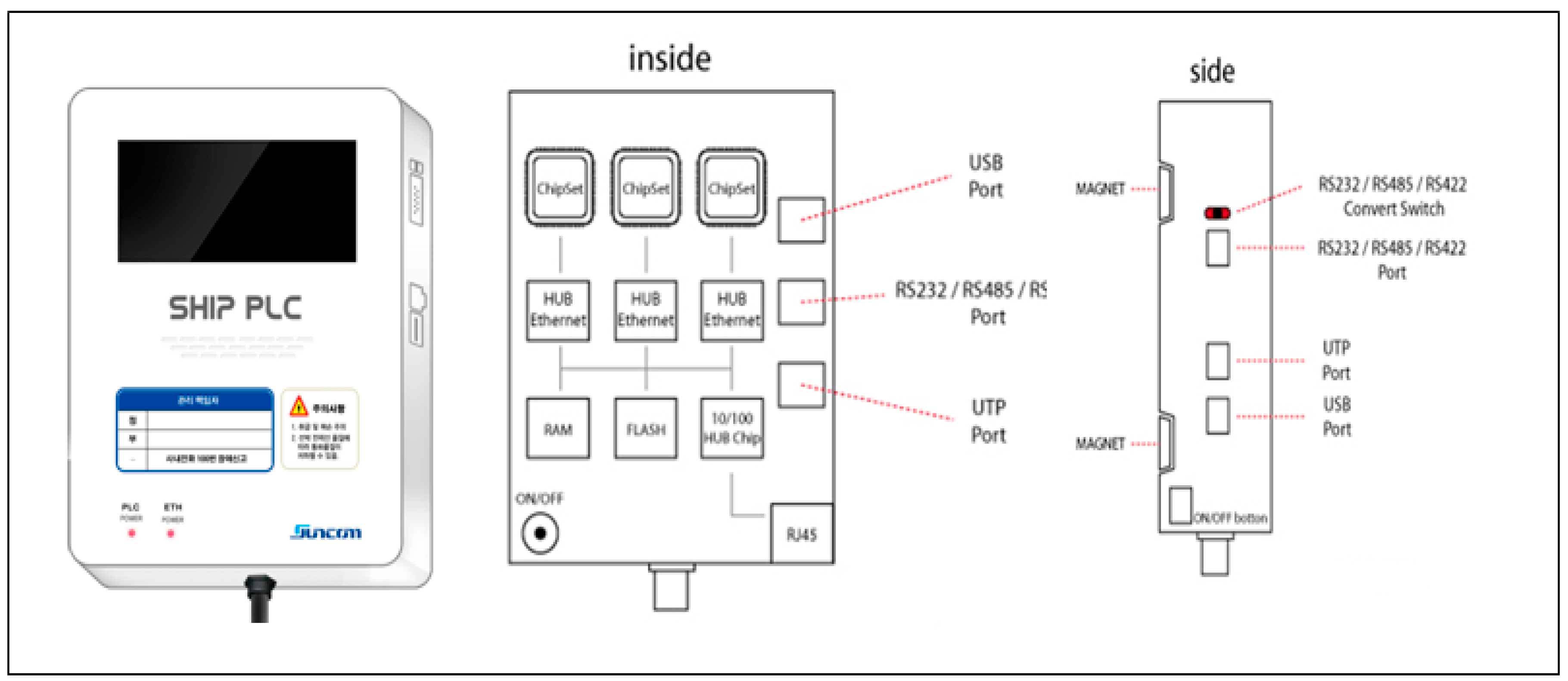
Figure 13.
Algorithm of the PLC master coupler PCB.
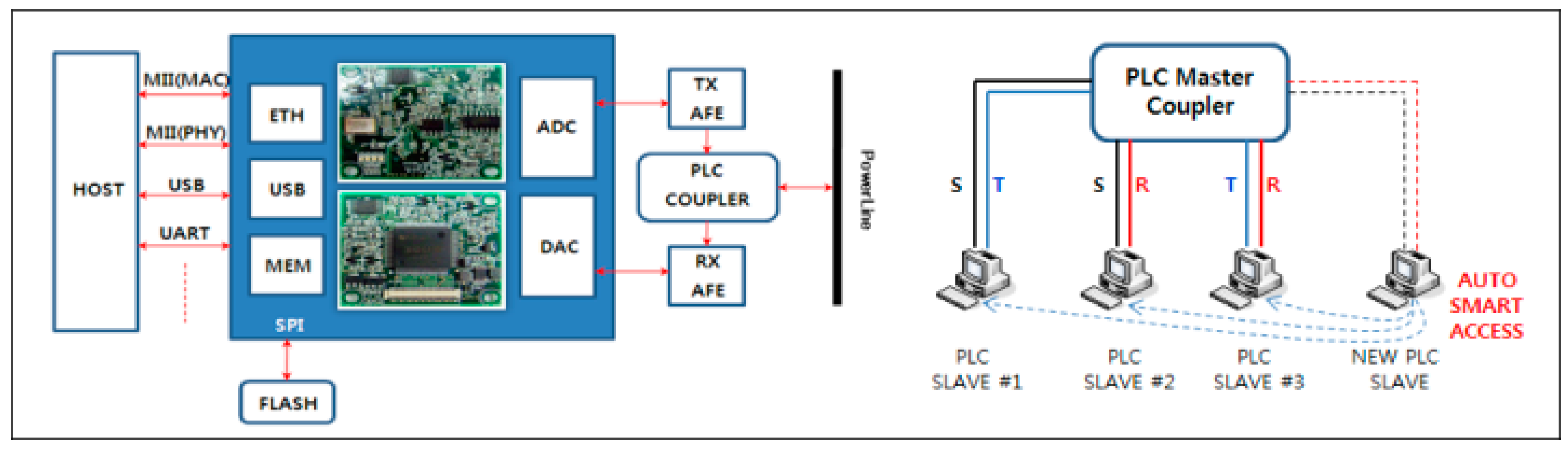
Figure 14.
Diagram of the PLC slave modem.

Figure 15.
Diagram of the PLC repeater.

Figure 16.
Ship power line communication installation process.

Figure 17.
Voice quality test using PLC-based TCP/IP communication.

Figure 18.
Data quality test using PLC-based TCP/IP communication.


Table 1.
Specifications of the MCU.
| Parts | Specification | Usages | |
|---|---|---|---|
| Housing case | Material | steel | Protect embedded PCB circuits with anti-flamming, water-proof, dust protective design |
| Paint | flame resistant power coating | ||
| Fastening tools | wall-mounting (magnet type) and pipes fastening brakets | ||
| Power connection | water-proof/dust protection connectors | ||
| UTP connection | water-proof/dust protection connectors | ||
| Ventilation | water-proof vent | ||
| Housing door | double doors (inner door—LED display window, outer doorlock) | ||
| PLC MASTER | PHY Rate(Mbps) | 200 | Power Line data carrier |
| Frequency | 2~34 MHz | ||
| Power Consumption | 10 W | ||
| Connect Port | Ethernet port: RJ 45 × 3 | ||
| Power | 110~220 VAC (50/60 Hz) | ||
| Phases & Capacity | 3Ø3 W | ||
| Operating Temperature | 0~40 °C | ||
| Humidity (%) | 10~90 | ||
| Option | For Outdoor Version | ||
| NOISE FILTER | Application | 2 Phase 2 Wire | Shut out noises unintentionally and indirectly generated by PoE and Swiching equipments |
| Max. Current | 60 A | ||
| Frequency | 1.7~30 MHz | ||
| Rated Voltage | <380 | ||
| Dimension | 130 × 80 × 75 (L × W × H mm) | ||
| OperatingTemp | −60~60 °C | ||
| SWITCHING | WAN Interface | 1 × 10/100 Mbps WAN—automatic cable detection | Wireless linking with PLC master, Data link |
| LAN Interface | 4 × 10/100 Mbps PC Por—automatic cable detection | ||
| DRAM | 8 Mbytes | ||
| FLASH | 2 Mbytes | ||
| Protocols | HTTP, DHCP, PPPoE | ||
| App. Protocol | H323 | ||
| POWER BREAKER | Rated Voltage | <460 | Protection of equipment from external overvoltage & overcurrent, Main power supply |
| Rated Current | 50 A | ||
| Phases & Capacity | 3Ø3 W | ||
| Interrupt Capacity | 2.5 kA | ||
| Certification | safety certification | ||
| Standard tripping method | fully electronic/Oil Drash Pot | ||
Table 2.
Specifications of the PLC repeater.
| Parts | Specification | Usages | |
|---|---|---|---|
| Case | Material | ABS, UL94-HB & UL94-V0 fire retardant class | Protect embedded PCB circuits with anti-flamming, water-proof, dust protective design |
| stening tools | Wall-mounting (magnet type) | ||
| Power supply connection | water-proof, dust protection power supply connector | ||
| UTP connection | water-proof, dust protection power supply connector | ||
| Handle | 30° gap, 12-phase rotation | ||
| Ventilation | water-proof vent | ||
| PLC | PHY Rate(Mbps) | 200 | Power Line data carrier |
| Frequency(MHz) | 2~34 | ||
| Power Consumption (W) | 10 | ||
| Connect Port | Ethernet port : RJ 45 × 1 | ||
| Power Supply | 110~220 VAC (50/60 Hz) | ||
| Operating Temperature (°C) | 0~40 | ||
| Smart Access | Smart Access for Intelligent Repeating, Plug & Play | ||
| Humidity (%) | 10~90 | ||
Table 3.
Specifications of the DLF product.
| Parts | Specification | Usages | |
|---|---|---|---|
| Housing case | Material | ABS, UL94-HB & UL94-V0 fire-retardant class | Protect embedded PCB circuits with anti-flamming, water-proof, dust protective design |
| Fastening tools | wall-mounting (magnetic type) | ||
| Power connection | water-proof, dust protection power supply connector | ||
| UTP connection | water-proof, dust protection connector | ||
| Handle | 30° gap, 12-phase rotations | ||
| Ventilation | water-proof vent | ||
| DLC | PHY Rate (Mbps) | 200 | Power Line data carrier |
| Frequency (MHz) | 2~34 | ||
| Power Consumption (W) | 10 | ||
| Connect Port | Ethernet port: RJ 45 × 1, BNC Port ×1 | ||
| Power Supply | 110~220 VAC (50/60 Hz) | ||
| Operating Temperature (°C) | 0~40 | ||
| Humidity (%) | 10~90 | ||
| xLine Coupler | 2 Wire Connector, BNC Pig-Tail | ||
| NOISE FILTER | Application | 2 Phase 2 Wire | Shut out noises unintentionally and indirectly generated by wireless linking and Femto equipments |
| Max. Current (A) | 10 | ||
| Frequency | 150 KHz ~30 MHz | ||
| Rated Voltage | <2200 | ||
| Certification | UL, EMI | ||
| Wire-wireless IP route | CPU | 384 MHz MIPS 32 bit | Femto & Wireless link IP Sharing |
| WAN Interface | 1 × 10/100 Mbps WAN—automatic cable detection | ||
| LAN Interface | 4 × 10/100 Mbps PC Port—automatic cable detection | ||
| Wireless Interface | 802.11 b/g/n(Draft)/2.4 GHz | ||
| DRAM | 16 Mbytes | ||
| FLASH | 2 Mbytes | ||
| Protocols | HTTP, DHCP, PPPoE | ||
| QoS | Rate limitting, Rate Grantee | ||
© 2018 by the authors. Licensee MDPI, Basel, Switzerland. This article is an open access article distributed under the terms and conditions of the Creative Commons Attribution (CC BY) license (http://creativecommons.org/licenses/by/4.0/).
Share and Cite
MDPI and ACS Style
Huh, J.-H.; Koh, T.; Seo, K. Design of a Shipboard Outside Communication Network and Its Testbed Using PLC: For Safety Management during the Ship Building Process. Processes 2018, 6, 67. https://doi.org/10.3390/pr6060067
AMA Style
Huh J-H, Koh T, Seo K. Design of a Shipboard Outside Communication Network and Its Testbed Using PLC: For Safety Management during the Ship Building Process. Processes. 2018; 6(6):67. https://doi.org/10.3390/pr6060067
Chicago/Turabian StyleHuh, Jun-Ho, Taehoon Koh, and Kyungryong Seo. 2018. "Design of a Shipboard Outside Communication Network and Its Testbed Using PLC: For Safety Management during the Ship Building Process" Processes 6, no. 6: 67. https://doi.org/10.3390/pr6060067
Note that from the first issue of 2016, this journal uses article numbers instead of page numbers. See further details here.