


Abstract
Coal reservoirs exhibit strong heterogeneity and complex in situ stress conditions, and the initiation and propagation of hydraulic fractures are jointly controlled by reservoir geology and perforation design. A damage–seepage coupled numerical model was established on the COMSOL Multiphysics platform (Version 6.2) by combining the maximum tensile stress criterion and the Mohr–Coulomb criterion with stress-dependent porosity–permeability relations, and was verified against the classical Hubbert–Willis analytical solution. The model was used to simulate the whole fracturing process, the effect of natural fractures, horizontal-well multi-perforation fracturing, and the sensitivity of breakdown pressure to perforation parameters under six reservoir conditions. The results show that: the bottomhole pressure evolves in a “buildup–breakdown–drop–re-accumulation” pattern, and the secondary breakdown pressure (about 22 MPa) is approximately 15% lower than the initial one (about 26 MPa), while the near-fracture permeability rises from 0.246 mD to more than 40 mD; natural fractures delay the first breakdown from about 40 s to 46 s but accelerate the post-breakdown propagation and enlarge the high-permeability region; horizontal-well fracturing initiates multiple transverse, feather-like fractures from the perforations, with a first breakdown pressure of 11.4 MPa at 20 s; doubling the initial permeability raises the breakdown pressure by 1.4–1.6 MPa, making initial permeability the most sensitive reservoir factor, followed by in situ stress orientation and rock strength; and the favorable perforation combination under the minimum-breakdown-pressure criterion shifts with reservoir conditions, e.g., from “8 holes/m, 60-degree” to “16 holes/m, 30-degree” when the maximum principal stress rotates from horizontal to vertical. These results provide a quantitative basis for the optimization of perforation parameters in coal-reservoir fracturing.
1. Introduction
Hydraulic fracturing creates fractures in the reservoir and extends seepage channels through high-pressure fluid, and is a key technical means for stimulation of coal reservoirs [1,2]. China is rich in coalbed methane resources [3]; however, as development advances toward more complex coal reservoirs, higher in situ stress levels, rock densification, and heterogeneity all make fracture initiation and propagation more complicated [4,5,6]. The widely developed natural fractures further affect fracture propagation. Laboratory physical simulation of hydraulic fracturing is limited by sample size and stress-loading capacity, making it difficult to fully reproduce the formation and evolution of fracture networks. Numerical simulation has therefore become an important means of studying the initiation, propagation, and seepage coupling behavior of hydraulic fractures in reservoirs [7,8].
Traditional numerical studies of hydraulic fracturing treat rock as a brittle homogeneous medium, which cannot describe the interaction between post-peak damage and the evolution of seepage capacity during fracturing. In contrast, damage-mechanics-based methods use a damage variable to uniformly characterize the rock failure process [9,10], and can be coupled with porous media seepage equations to realize multi-field coupled simulation of stress–damage–seepage [11,12]. Such models can dynamically reproduce the evolution of breakdown pressure, fracture network propagation, and reservoir permeability enhancement, providing an effective approach for the analysis of coal reservoir fracturing.
Previous studies have shown that reservoir factors such as in situ stress state, rock strength, initial permeability, and natural fracture development exert significant control over breakdown pressure and fracture morphology [13,14,15,16]. Tang et al. [13] systematically analyzed the influence of in situ stress on hydraulic fracturing in coalbed methane wells and found that the horizontal stress difference and the orientation of the maximum principal stress jointly determine fracture initiation pressure and propagation direction. Zhu et al. [14] further pointed out that natural fracture weak planes significantly lower the breakdown pressure threshold and cause fractures to deflect and bifurcate along the weak planes. Huang et al. [15] established a method for predicting fracture types in coalbed methane reservoirs based on the natural fracture initiation criterion, and clarified the reactivation mechanism of natural fractures under different stress conditions. Tan et al. [16], through true triaxial hydraulic fracturing experiments, observed typical behaviors such as capture, deflection, and branching when hydraulic fractures intersect natural fractures, confirming that non-planar propagation under the coexistence of multiple fractures is the main cause of fracture network complexity. However, most of these studies were conducted independently for a single reservoir factor, and the understanding of the multi-peak evolution of breakdown pressure, damage accumulation, and the staged response characteristics of permeability enhancement throughout the fracturing process, as well as the multi-factor coupling mechanism, remains insufficient.
Perforation is a key link connecting the wellbore and the reservoir. The perforation technique, orientation, density, and diameter directly affect the fracture initiation position, propagation morphology, and breakdown pressure level through mechanisms such as stress concentration, perforation friction, and inter-perforation stress interference [17,18,19]. Liu et al. [17] derived an analytical model for the perforation initiation azimuth angle based on in situ stress and established optimization criteria for matching the perforation orientation with the principal stresses. Li et al. [18] proposed a perforation optimization design method for pre-fracturing wells and examined the influence of perforation density and diameter on near-wellbore initiation pressure and fracture connectivity. Jin et al. [19] established an initiation pressure model for vertical wells in naturally fractured formations and revealed the regulation of initiation pressure by perforation orientation under natural fracture conditions. In summary, the matching relationship between perforation parameters, in situ stress, and natural fractures is complex; unreasonable perforation designs can easily induce inter-perforation stress interference, elevate initiation pressure, and reduce fracturing controllability. Systematic optimization of perforation parameters for specific reservoir conditions therefore urgently needs further investigation.
Despite these advances, several research gaps remain in the hydraulic fracturing of coal reservoirs. First, although stress-dependent porosity/permeability relationships and damage-based fracturing models have been extensively studied, in most existing models the damage-induced stiffness degradation and the stress- and damage-dependent evolution of porosity and permeability are only partially coupled, so that the mutual feedback between fracture propagation and seepage-capacity evolution throughout the whole fracturing process is not fully reproduced. Second, damage–seepage modeling has rarely been combined with systematic, quantitative perforation-parameter optimization; most parameter studies consider a single factor and rely on qualitative evaluation. Third, how reservoir conditions (in situ stress orientation, rock strength, and initial permeability) modify the response of fracturing performance to perforation density, diameter, and orientation remains poorly understood.
To this end, this paper establishes a damage–seepage coupled numerical model of hydraulic fracturing in coal reservoirs, uses the maximum tensile stress criterion and the Mohr–Coulomb criterion to determine rock failure, describes post-peak degradation through the dynamic evolution of the damage variable, and introduces the stress–porosity–permeability coupling relationship to characterize the evolution of seepage capacity. The staged characteristics of bottomhole pressure, fracture propagation, and permeability evolution during fracturing are systematically simulated, and the controlling characteristics of natural fractures on fracture morphology and stress distribution are clarified. Furthermore, the breakdown pressure response under multi-factor combinations including perforation density, perforation diameter, perforation orientation, in situ stress conditions, rock strength, and initial permeability is analyzed, so as to provide a theoretical basis for the optimization of perforation parameters and fracturing design in coal reservoirs.
The core novelty and main contributions of this work are as follows. (1) A fully coupled damage–seepage model is established, and a whole-process simulation framework is developed that links bottomhole-pressure evolution, fracture propagation, and permeability enhancement. (2) A full-combination sensitivity analysis of perforation orientation and density (16 combinations) is conducted under six reservoir conditions with the breakdown pressure as a unified quantitative index, from which condition-adaptive perforation design principles are derived.
The remainder of this paper is organized as follows. Section 2 presents the failure criteria, the damage evolution law, the damage–seepage coupling relations, the model setup, and the model verification. Section 3 simulates the dynamic response of the whole fracturing process, including the effects of natural fractures and horizontal-well conditions. Section 4 analyzes the influence of perforation parameters under different geological conditions and proposes perforation design principles. Section 5 discusses the boundary-size effect, model limitations, and future work.
2. Numerical Simulation Method
2.1. Rock Failure Criterion and Damage Evolution
During hydraulic fracturing, the failure of coal is controlled by the stress state, and the maximum tensile stress criterion and the Mohr–Coulomb criterion are used to jointly determine the initiation behavior of the rock [1,2,20]:
Equation (1) is the maximum tensile stress criterion, where ft is the tensile strength of the rock, in Pa; Equation (2) is the Mohr–Coulomb criterion, where fc is the compressive strength of the rock, in Pa, and φ is the internal friction angle of the rock, in deg. When the stress state satisfies either the maximum tensile stress criterion or the Mohr–Coulomb criterion, the reservoir fails under tension or compression [9,10].
F1 = σ1 − ft
To describe the mechanical degradation of rock after failure, an elastoplastic damage model is adopted, in which the damage variable D (0 <= D <= 1) uniformly characterizes the continuous degradation process of rock from intact to fractured: D = 0 indicates that the rock is undamaged, and D = 1 indicates complete failure. When F1 >= 0, the rock undergoes tensile failure, and the relationship between the damage variable D and strain is
When F2 >= 0 is satisfied, the rock undergoes shear failure, and the relationship between the damage variable D and strain is
In the equations, λ is the residual tensile strength coefficient, λ = ftr/ft0, where ftr is the residual tensile strength and ft0 is the initial tensile strength; εt0 is the tensile strain of the rock at the elastic strain limit state; η is the ultimate strain coefficient, εtu = η × εt0. Once the rock enters the damage state, its bearing capacity gradually degrades with damage accumulation, avoiding the unrealistic abrupt stress change after failure in linear elastic models.
2.2. Damage–Seepage Coupling Relationship
Rock deformation and pore fluid migration are mutually constrained. According to the principle of elastic damage, the relationship between the elastic parameters of the rock before and after damage is
In the equation, E0 is the elastic modulus before damage and E is the elastic modulus after damage. That is, the higher the degree of damage, the lower the rock stiffness, and stress is transferred to the surrounding elements, thereby driving the self-organized propagation of fractures. During rock damage or failure, the relationship between porosity and stress state is [11]
In the equation, φ0 is the porosity in the stress-free state; αφ is the stress sensitivity coefficient of porosity, generally taken as 5.0 × 10⁻⁸ Pa−1; σv is the mean effective stress, equal to the mean triaxial stress minus the pore pressure; and φr is the limiting porosity under high stress.
E = (1 − D)E0
During rock damage or failure, the relationship between permeability and stress is [12]
In the equation, k0 is the permeability of the rock in the stress-free state and k is the permeability of the rock under the stress state.
Physically, the damage–seepage coupling in the model proceeds through a closed interaction loop. Fluid injection raises the pore pressure and reduces the effective stress; once the effective stress state satisfies the failure criterion, damage initiates and degrades the elastic modulus according to Equation (5), so that stress is redistributed; the resulting damage and stress change, in turn, increase the porosity and permeability according to Equations (6) and (7), enhancing the local flow and further modifying the pore-pressure field. This progressive pore pressure-effective stress–damage–permeability interaction governs the fracture propagation and the staged permeability enhancement observed in Section 3. Similar progressive pore-pressure/geomechanics coupling has been emphasized in coupled fluid-flow/geomechanical modeling of other unconventional reservoirs; for example, Guo et al. [21] developed a poro-elasto-viscoplastic-dynamic model for depressurization in natural gas hydrate-bearing sediments, in which pore-pressure changes progressively modify the mechanical response and deformation of the porous sediment, leading to stiffness reduction and stress redistribution analogous to the damage-induced degradation considered here.
2.3. Model Establishment and Parameter Selection
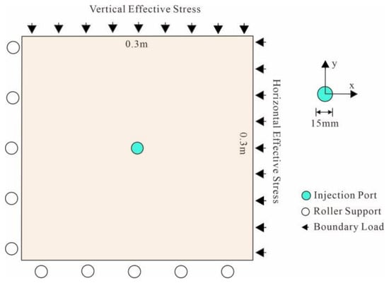
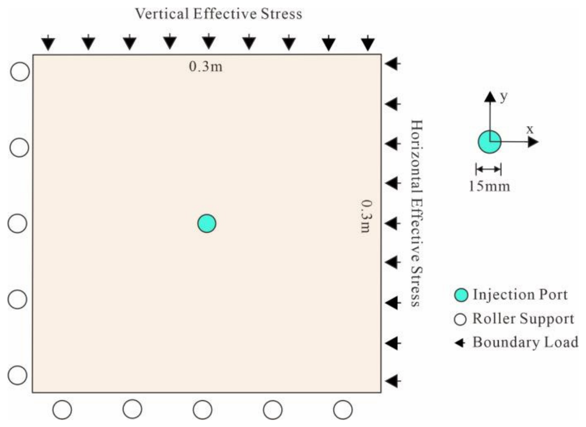
The model adopts a two-dimensional plane-strain assumption with geometric dimensions of 0.3 × 0.3 m and an injection point set at the center (Figure 1). The boundary conditions are as follows: a vertical stress σv = 24.12 MPa is applied to the upper and lower boundaries (along the y-direction), a horizontal stress σh = 16.43 MPa is applied to the left and right boundaries (along the x-direction), and the surrounding boundaries are fixed-displacement boundaries; the initial pore pressure is 0.1 MPa, and the fracturing fluid is continuously injected from the injection point at a constant rate to simulate the whole process of reservoir hydraulic fracturing.
Figure 1.
Dimensions and boundary conditions of the hydraulic fracturing numerical model.
The model parameters shown in Table 1. The rock mechanical parameters are determined by laboratory uniaxial, triaxial compression, and Brazilian splitting tests [22,23]; the reservoir physical parameters (initial porosity, initial permeability, etc.) are obtained from core physical property analysis and pulse permeability tests; and the density and viscosity of the fracturing fluid are taken as typical values of a water-based fracturing fluid. The in situ stress is given according to the statistical relationship between regional in situ stress and burial depth [1,2], and can be adjusted within a typical range to investigate different stress combinations. All parameters fall within the common range of coal reservoirs and are thus general and representative.
Table 1.
Model parameters.
All simulations were performed on the COMSOL Multiphysics finite-element platform. The Solid Mechanics interface and the Darcy’s Law interface were coupled through a fully coupled solver, and the failure criteria, damage evolution, and stress/damage-dependent porosity and permeability described by Equations (1)–(7) were implemented through user-defined constitutive expressions and field variables. The 0.3 m × 0.3 m model was discretized into 150 × 150 uniform quadrilateral elements (element size 2 mm). The horizontal-well model adopted the same element size. Key modeling assumptions and software-related limitations are summarized in Table 2.
Table 2.
Key modeling assumptions and software limitations.
2.4. Model Verification
To demonstrate that the proposed model can reasonably reproduce the fracture initiation pressure and propagation behavior, the base case of Section 2.3 is verified against the classical analytical solution and published experimental results.
For a circular opening under biaxial far-field stress, the classical Hubbert–Willis elastic solution predicts the breakdown pressure as Pb = 3σh − σv + ft [1,2]. Substituting σh = 16.43 MPa, σv = 24.12 MPa, and ft = 1.61 MPa gives Pb = 26.78 MPa. The simulated first breakdown pressure of approximately 26 MPa deviates from the analytical value by less than 3%, indicating that the model captures the stress-controlled initiation behavior well. The simulated fracture initiates at the positions of maximum tangential tensile stress on the injection-port wall and then propagates along the direction perpendicular to the minimum principal stress, which is consistent with classical hydraulic-fracturing theory [1,2,24].
These comparisons indicate that the proposed model can reasonably reproduce the fracture initiation pressure and propagation behavior and is suitable for the subsequent parameter analyses.
3. Dynamic Response Simulation of the Hydraulic Fracturing Process
Based on the damage–seepage coupled numerical model, the dynamic response characteristics of coal reservoirs during hydraulic fracturing are systematically simulated; the variation characteristics of bottomhole pressure and fracture propagation during fracturing are analyzed; and the fracture propagation behaviors under different factors are compared, providing a physical basis for the subsequent optimization of perforation parameters.
3.1. Evolution Characteristics of Bottomhole Pressure
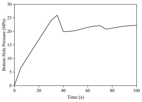
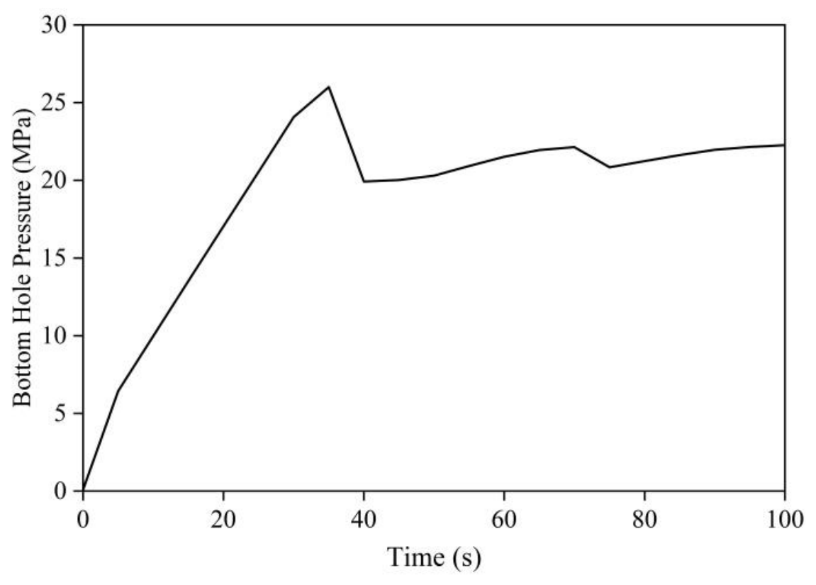
The variation in bottomhole pressure directly reflects the time and degree of fracture breakdown. During reservoir fracturing, the bottomhole pressure generally exhibits a pattern of rapid buildup, drop after the peak, and then slow re-accumulation (Figure 2). After the fracturing fluid is injected at a constant rate, the fluid in the reservoir is gradually compressed and the bottomhole pressure rises rapidly. At this stage, no macroscopic failure has occurred in the reservoir, and the pressure rise mainly reflects fluid compression [25]. When the bottomhole pressure reaches the reservoir breakdown pressure, the rock initiates fracture and propagates gradually, and the pressure drops significantly after reaching the first peak, indicating that the fracture has formed and the fluid has entered the fracture and filled the void space. Thereafter, the bottomhole pressure undergoes a cyclic process of re-accumulation and filling. During the whole simulation period, the reservoir exhibits two pressure peaks, i.e., two breakdown events occur. The pressure required for the second breakdown is significantly lower than that for the first breakdown. This is mainly because local fractures have been partially formed after the first breakdown; the stress within the reservoir is redistributed, and the excitation energy required for subsequent breakdown is reduced.
Figure 2.
Variation in bottomhole pressure during reservoir fracturing.
3.2. Fracture Propagation Characteristics
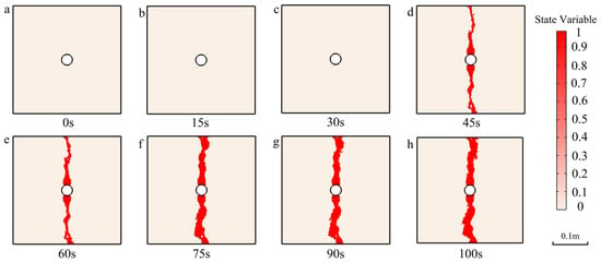
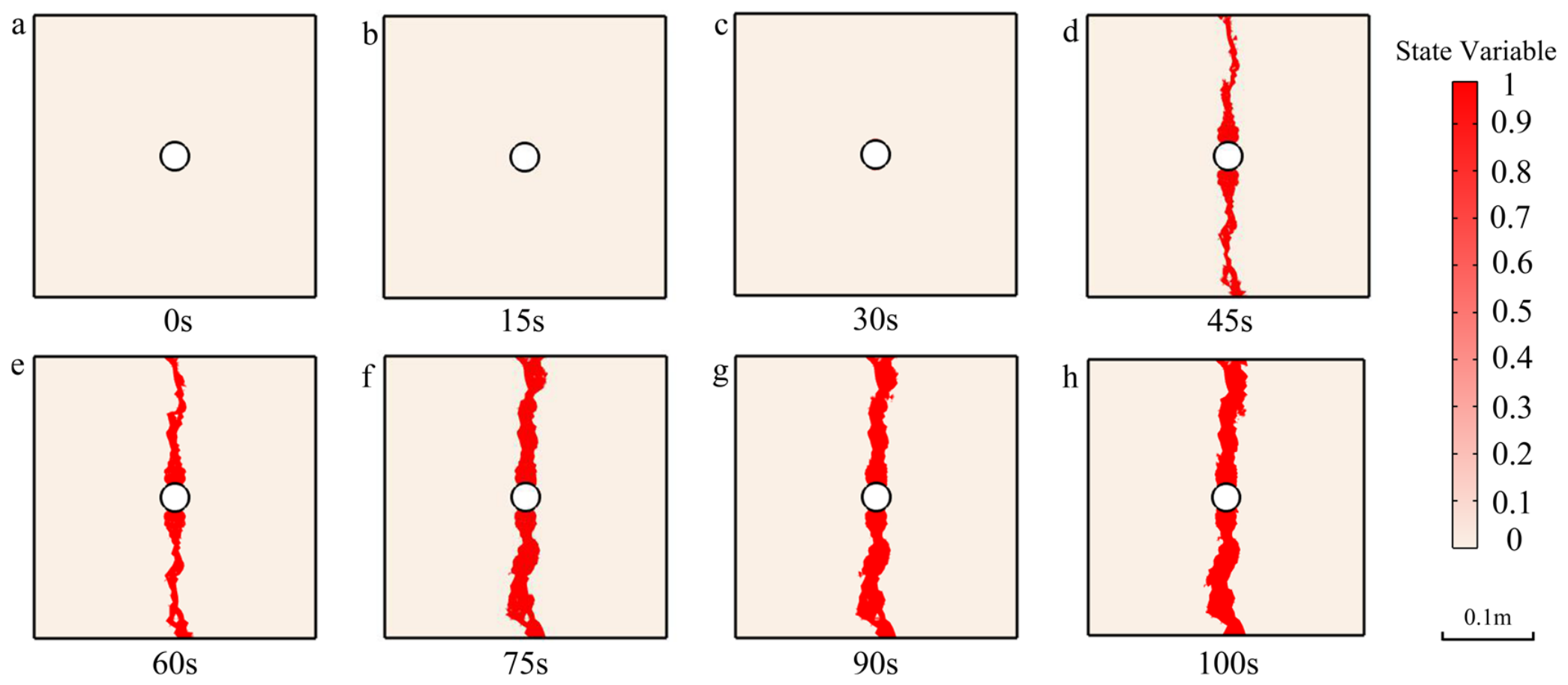
The degree of failure is characterized by a state variable. The fracture propagation process in the reservoir is staged. At 30 s of injection, the state variable remains 0 and no failure occurs (Figure 3a–c), indicating that the reservoir is in the elastic compression stage and the bottomhole pressure keeps accumulating; after 30 s, fractures initiate and propagate rapidly along the y-direction, reaching the model boundary at 45 s (Figure 3d). The stress condition adopted in the simulation is that the vertical stress is greater than the horizontal stress, so fractures first propagate along the direction perpendicular to the minimum principal stress (the x-direction) [1,2,25]. After 75 s, the fractures have propagated to the model boundary and the fractured zone gradually widens with time (Figure 3e–h). At this point, fracture propagation shifts from longitudinal extension to width increase, indicating that when the in situ reservoir encounters a barrier boundary, the fracture is promoted to expand further in the width direction, which is favorable for forming a larger fracture width.
Figure 3.
Evolution of fracture propagation during the fracturing process. (a) 0 s; (b) 15 s; (c) 30 s; (d) 45 s; (e) 60 s; (f) 75 s; (g) 90 s; (h) 100 s.
It can also be seen that in the homogeneous model, no significant bifurcation occurs in the fractures, which are mainly controlled by the in situ stress state and generally propagate directionally perpendicular to the minimum principal stress [1,2,25]. After the fractures propagate to the model boundary, the propagation mode changes from longitudinal extension to width increase, and the barrier boundary is favorable for forming a larger fracture width.
It should be noted that once the fractures reach the model boundary, the subsequent stress and pore-pressure fields are inevitably influenced by the boundary confinement, and the widening of the damaged region after boundary contact is partly a boundary-size effect; this effect is discussed in Section 5.1.
3.3. Permeability Evolution Characteristics
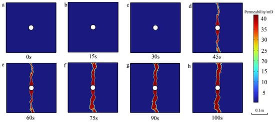
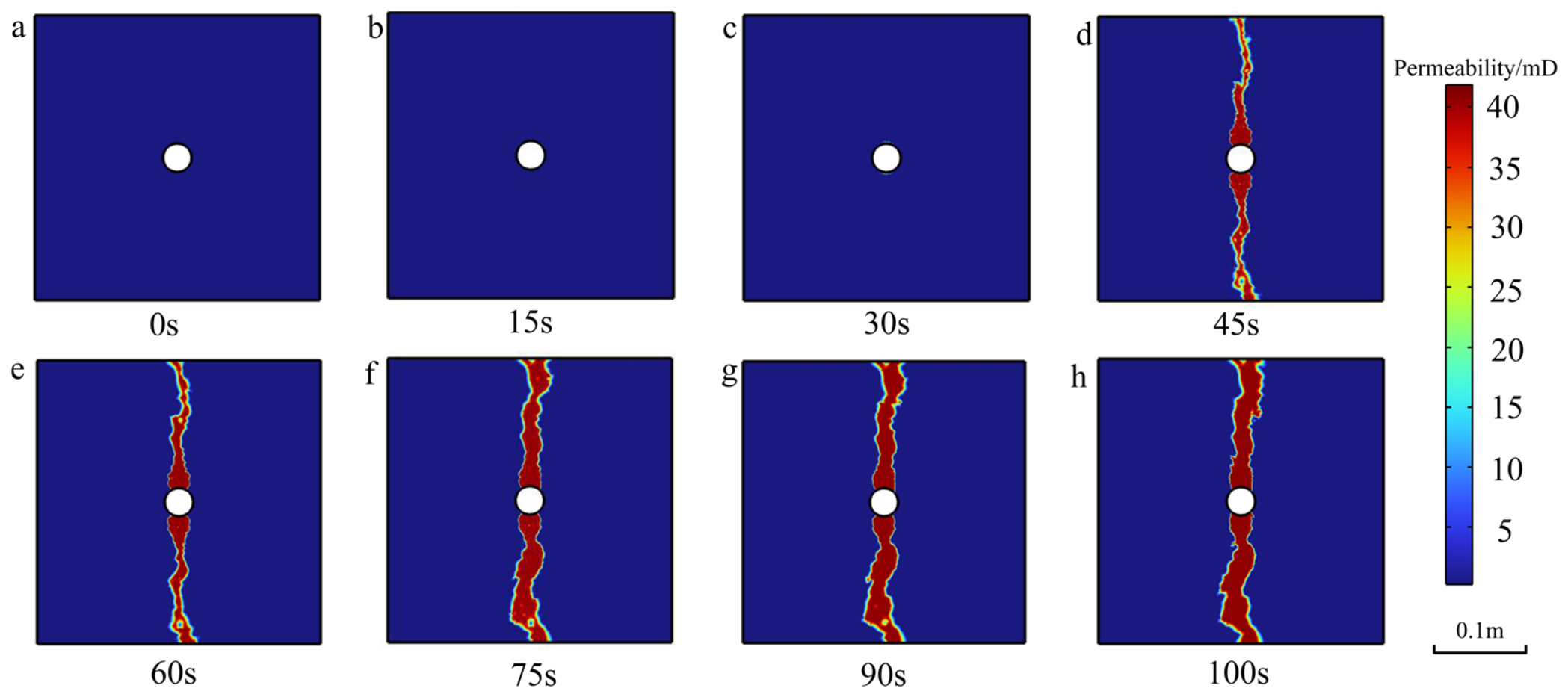
The generation of fractures during fracturing directly leads to a significant increase in reservoir permeability [11,12]. The initial permeability of the reservoir is 0.246 mD. Within the first 30 s, because fractures have not yet formed on a large scale, the permeability only rises slowly to 0.286 mD; at 45 s of injection, the permeability in the y-direction suddenly jumps to 41.4 mD, accompanied by the continuous extension of fractures along this direction; at 75 s, the secondary breakdown abruptly enlarges the fractured region; after 100 s, the fracture network continues to evolve and improve, and the reservoir seepage capacity is greatly enhanced (Figure 4).
Figure 4.
Evolution of permeability distribution during reservoir fracturing. (a) 0 s; (b) 15 s; (c) 30 s; (d) 45 s; (e) 60 s; (f) 75 s; (g) 90 s; (h) 100 s.
Overall, during the early injection stage, the permeability rises slowly, reflecting the limited improvement of reservoir seepage capacity before fractures initially form. When fractures near the wellbore propagate rapidly in a specific direction within a short time, the permeability suddenly jumps; as the fractures propagate to the model boundary, the fractures enlarge significantly and the local permeability increases further, with seepage channels extending along the boundary-constrained direction; after the fracture network forms, the secondary breakdown event changes the seepage channels and further enhances the overall permeability; with increasing injection time, the permeability expands progressively, but the change is relatively small.
3.4. Influence of Natural Fractures
Natural fractures are widely developed in reservoirs and, owing to their low failure strength, can significantly affect fracture propagation during hydraulic fracturing [15,26,27,28]. To quantitatively evaluate the influence of natural fractures, the mechanical weak-plane effect is characterized by reducing the failure strength of the natural fracture region. In the model, 100 horizontal and 100 vertical natural fractures are set, with a fracture length of 0.02 m and a fracture porosity of 0.2 (Table 3), and two cases with and without natural fractures are simulated for comparison.
Table 3.
Simulated fracture parameters.
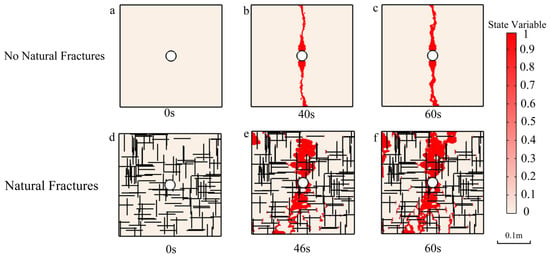
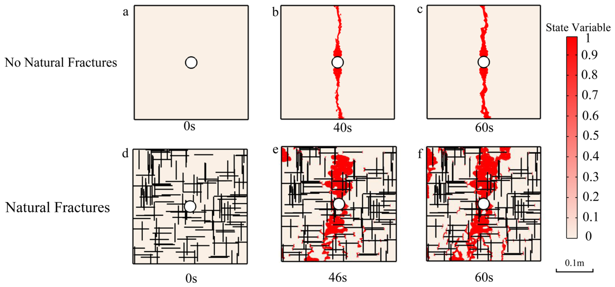
In terms of fracture morphology (Figure 5), for the reservoir without natural fractures, the first breakdown occurs at about 40 s, and the fractured region expands relatively slowly during 40–60 s; with natural fractures, the first breakdown time is delayed to about 46 s, but the expansion of the fractured region during 46–60 s is significantly accelerated. Although the first breakdown occurs slightly later in the presence of natural fractures, the natural fractures bring a larger pressure propagation range, making the fractured region wider overall. Moreover, owing to their higher connectivity, the fracture propagation speed after breakdown is markedly faster.
Figure 5.
Comparison of the fracturing state variables with and without natural fractures. The black thin lines represent natural fractures and the red zones represent the damaged, hydraulically fractured regions. (a) 0 s; (b) 40 s; (c) 60 s; (d) 0 s; (e) 46 s; (f) 60 s.
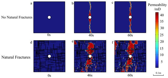
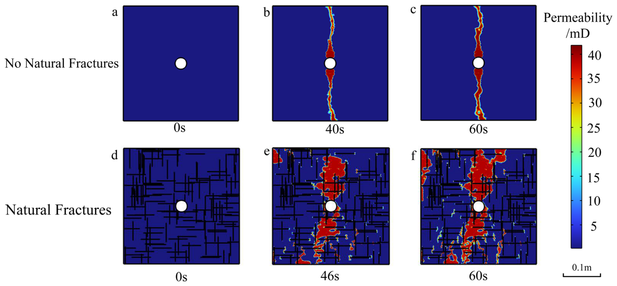
In terms of permeability, at the first breakdown, the peak permeability of the fractured region is about 41.4 mD and 40.2 mD with and without natural fractures, respectively, with a small difference; however, the high-permeability region is significantly enlarged, the spatial distribution of permeability coincides closely with the fractured region, and the greater the degree of failure, the higher the local permeability (Figure 6).
Figure 6.
Comparison of permeability with and without natural fractures. The black thin lines represent natural fractures. (a) 0 s; (b) 40 s; (c) 60 s; (d) 0 s; (e) 46 s; (f) 60 s.
Natural fractures have a significant influence on fracture propagation in the reservoir. Natural fractures promote the preferential propagation of fractures along their planes [27,28], and the high connectivity makes fracture propagation in the fractured region more rapid, significantly improving the seepage channels after fracturing. While increasing permeability, they are also accompanied by uneven distribution of local pressure, which affects the overall propagation of fractures. Therefore, in the fracturing design of coal reservoirs with developed natural fractures, the disturbance effect of natural fractures on the fracture propagation path and stress field should be fully considered.
3.5. Fracture Propagation in Horizontal Wells
Horizontal wells extend over long distances along the coal seam dip, significantly increasing the contact area between the wellbore and the reservoir and the drainage volume, effectively reducing near-wellbore seepage resistance and increasing the controlled reserves per well, and are especially suitable for low-permeability coal reservoirs with weak seepage capacity. Moreover, when the horizontal wellbore is oriented along the maximum horizontal principal stress direction, fractures can initiate simultaneously at multiple perforation intervals along the wellbore, forming multiple transverse fractures across the wellbore, which is favorable for improving fracture network complexity and overcoming the adverse effects of strong heterogeneity and developed natural fractures in coal reservoirs. The perforation technique directly affects the development mode and propagation morphology of reservoir fractures by controlling the injection direction, angle, and perforation shape. Among these techniques, abrasive jet perforation transports liquid carrying abrasives (such as quartz sand) through the surface high-pressure pump system to a nozzle for high-speed ejection, and forms perforations in the casing and wellbore wall by high-speed abrasion. It can not only achieve efficient perforation but also clean and remove plugging in the near-wellbore damaged zone, further enhancing the connectivity between the reservoir and the wellbore [5,29]. However, during fracturing of horizontal wells, fractures do not propagate along the wellbore in a single direction; instead, after initiating from each perforation, they extend directionally along the direction perpendicular to the minimum principal stress under the control of the far-field stress difference. Multiple fractures propagate competitively and interfere with each other, and their propagation morphology and breakdown pressure evolution are more complex than those of vertical wells.
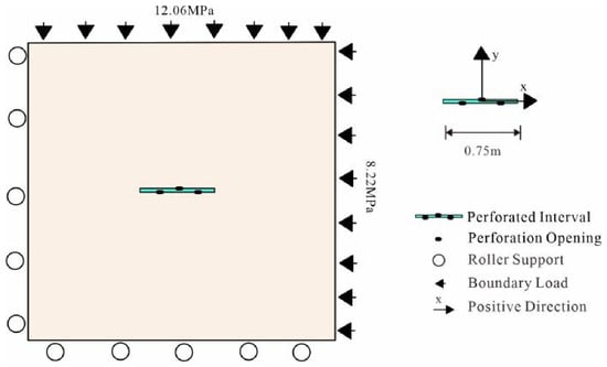
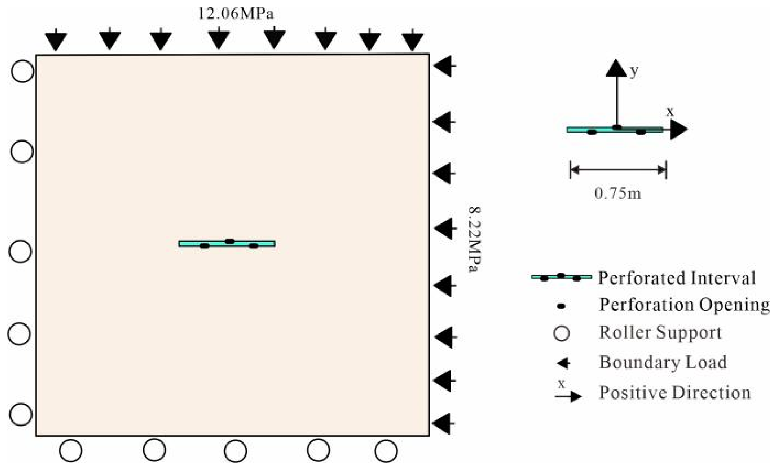
A fracturing simulation model for a horizontal well under abrasive jet perforation conditions is established (Figure 7). The determination of fracture propagation and damage evolution is based on Equations (3) and (4); the rock mechanical and seepage parameters are the same as in Table 1; and the perforation parameters are listed in Table 4.
Figure 7.
Simulation model of abrasive jet perforation fracturing in a horizontal well.
Table 4.
Injection parameters of the horizontal well model.
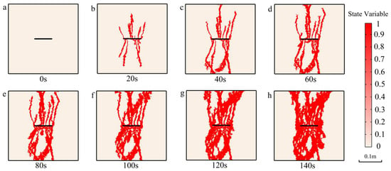
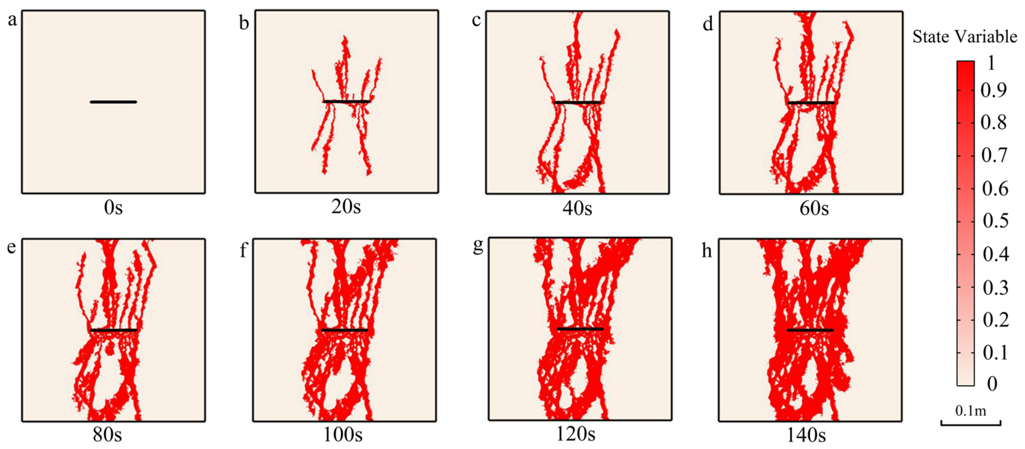
Under horizontal well conditions, fractures first initiate and propagate from the perforations along the y-direction (perpendicular to the minimum principal stress direction). In the early stage of breakdown, besides the main fractures at the perforations, some secondary fractures also form near other perforations and tend to extend along the y-direction. The whole breakdown evolution process can be divided into two characteristic stages (Figure 8). In the rapid directional extension stage (0–80 s), the stress concentration zones around the perforations successively reach the failure criterion, multiple fractures propagate competitively along the y-direction, and most fractures have approached or reached the model boundary by the end of this stage, with the fracture morphology dominated by linear directional extension and the propagation direction controlled by the far-field stress difference. In the widening and connection stage (80–140 s), after the main fractures connect through, the pressure within the fractures tends to be uniform, and the injection energy turns to drive the widening of existing fractures and the connection and bridging between adjacent fractures, so that the fracture network gradually forms and the seepage channel structure tends to be complex.
Figure 8.
Simulation results of abrasive jet perforation fracturing in the reservoir. (a) 0 s; (b) 20 s; (c) 40 s; (d) 60 s; (e) 80 s; (f) 100 s; (g) 120 s; (h) 140 s.
From the perspective of initiation mode, under horizontal well conditions, fractures mainly initiate from the perforations and exhibit an overall feather-like distribution, and as the fracturing time increases, some unperforated regions also gradually fail, indicating that the influence range of perforation stress concentration continuously expands with the propagation of pore pressure.
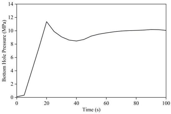
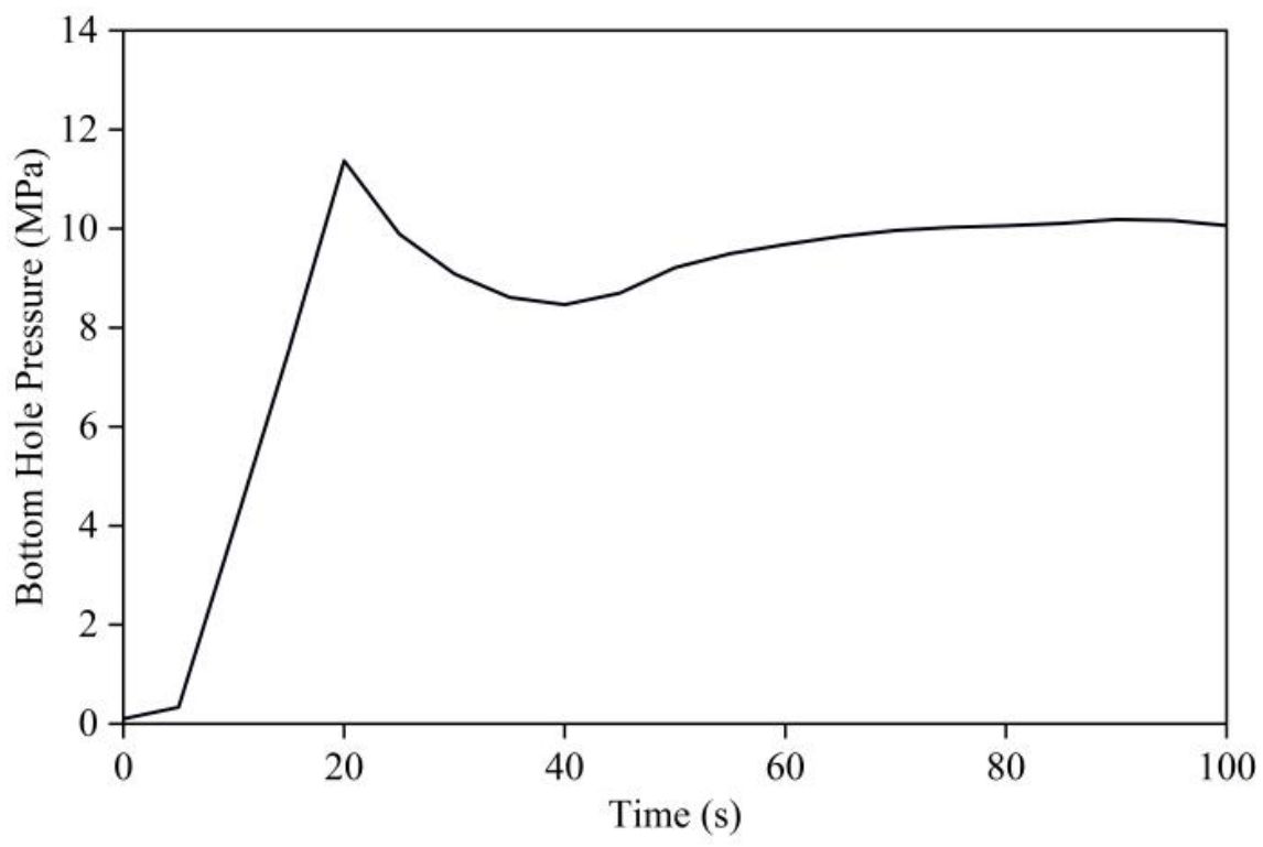
The bottomhole pressure curve exhibits a three-stage evolution characteristic (Figure 9). The bottomhole pressure rises rapidly with injection and reaches the first peak of 11.4 MPa at 20 s; subsequently, breakdown occurs and the pressure drops to 8 MPa; then, as the fractures further propagate, the pressure rises again to a maximum of nearly 10 MPa; after 70 s, the pressure fluctuates slightly around 10 MPa, reflecting that the fracture network gradually connects through and the breakdown tends to be stable.
Figure 9.
Variation in reservoir injection pressure.
4. Influence of Perforation Parameters on Fracturing Performance
Perforation is a key link connecting the wellbore and the reservoir. Especially under staged fracturing of horizontal wells, the perforation density, diameter, and orientation directly determine the fracture initiation position, propagation morphology, and breakdown pressure level, and thus control the fracturing stimulation performance. On the basis of the dynamic response simulation above, the fracture propagation and breakdown pressure evolution characteristics under multi-point perforation in the horizontal well section are analyzed, then the influence of perforation density and perforation diameter on fracturing performance is systematically analyzed, and, finally, for different combinations of in situ stress, rock strength, and permeability, the synergistic optimization of perforation orientation and perforation density is carried out, providing a basis for the design of perforation parameters in coal reservoir fracturing.
4.1. Influence of Perforation Density
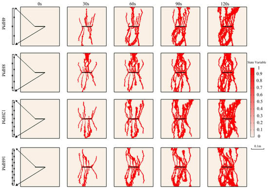
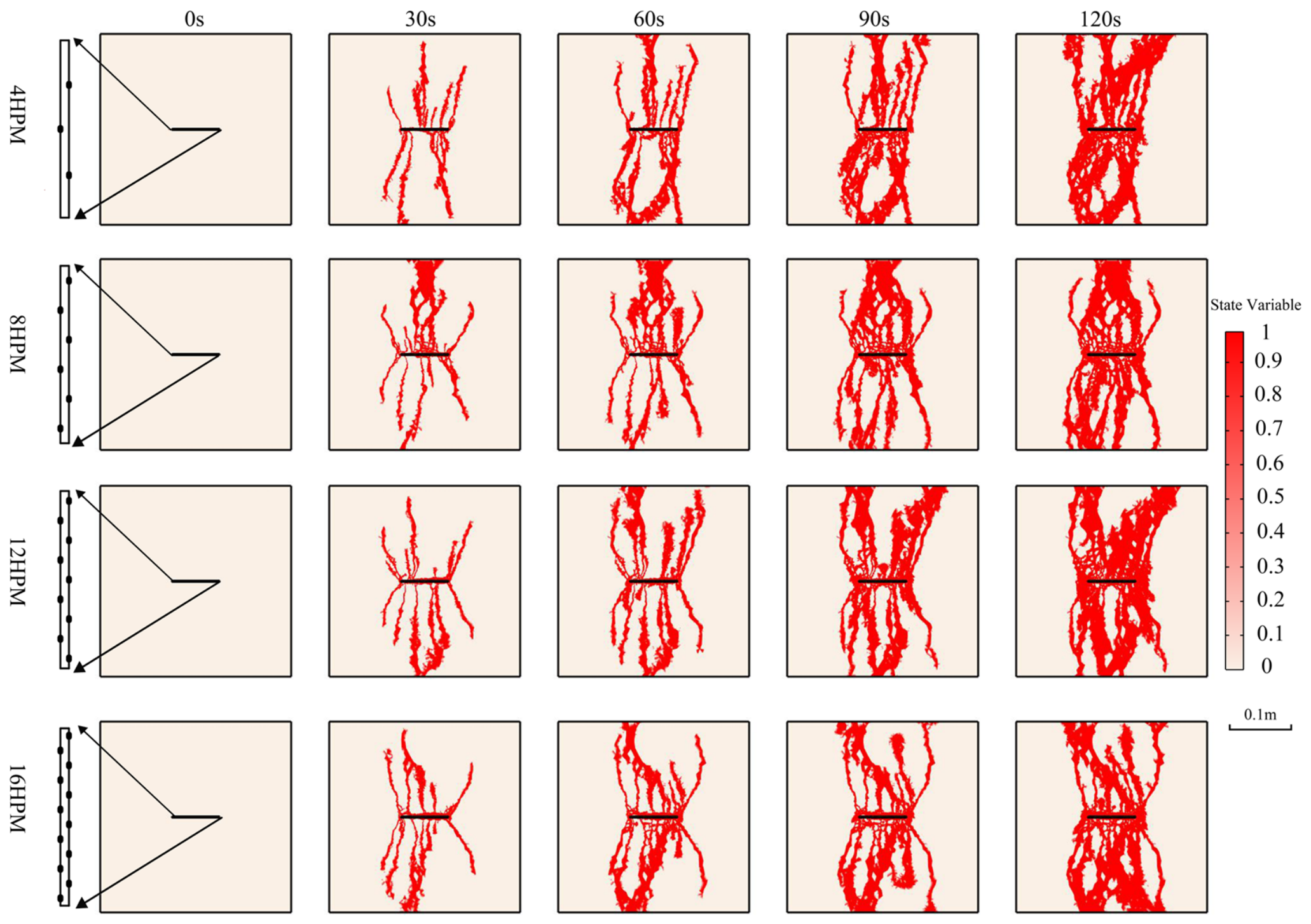
In terms of fracturing performance, a larger number of perforations provides more initiation sources, which is favorable for improving fracture network complexity and stimulated volume; meanwhile, stress interference exists between fractures initiated from adjacent perforations [7,30], and multiple fractures compete and divert the injected fluid, which may weaken the net pressure accumulation within a single fracture. For this purpose, four perforation densities of 4, 8, 12, and 16 holes/m are selected for comparative analysis.
In terms of fracture morphology, regardless of the perforation density, the fractured region always initiates from the perforations and their adjacent areas (Figure 10), indicating that the initiation position is mainly controlled by the superposition of pore pressure and stress concentration in the perforation-disturbed zone. As the perforation density increases, the number of fracture branches increases, the overall network structure becomes more complex, and the propagation speed accelerates accordingly. However, it is worth noting that under the parameter conditions of this simulation, the improvement of the fracture propagation speed by the perforation density is relatively limited. This indicates that the far-field propagation of fractures in the reservoir is mainly controlled by geological factors such as stress difference and rock mechanical properties, and the perforation density mainly acts on the near-wellbore initiation stage and has limited control over far-field propagation.
Figure 10.
Simulation results of fracturing under different perforation densities.
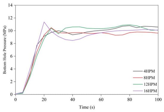
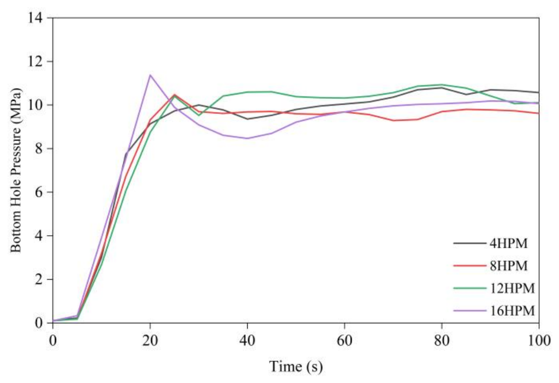
The pressure curves under the four perforation densities are generally consistent in shape (Figure 11), but two differences appear with increasing perforation density: the first breakdown pressure peak gradually increases, and the time required to reach the peak is significantly shortened. This is mainly because high-density perforation allows more perforations to take in fluid simultaneously, accelerating the bottomhole pressure accumulation rate and triggering initiation within a shorter time; meanwhile, multiple fractures propagate competitively in the near-wellbore region and interfere with each other, raising the equivalent threshold of overall initiation, so that the peak pressure increases and the initiation process becomes more intense.
Figure 11.
Variation in breakdown pressure under different perforation densities.
From both fracture morphology and breakdown pressure, it can be seen that there is a reasonable range for perforation density [30]: when the density is too low, the initiation sources are insufficient and the fracture network complexity is limited; when the density is too high, stress interference intensifies and the breakdown pressure rises. The systematic parameter simulation below will further provide the quantitative range of the optimal density under different reservoir conditions.
4.2. Influence of Perforation Diameter
Perforation diameter affects the initiation and propagation of hydraulic fractures through two paths. One is the stress concentration effect: the perforation diameter determines the size and intensity of the stress concentration zone around the perforation, thereby affecting the number and distribution of initiation positions. The other is the perforation friction effect: increasing the perforation diameter significantly reduces the fluid flow resistance at the perforation [30,31], changing the efficiency of pressure transmission from the bottomhole to the perforation tip. For this purpose, four perforation diameters of 10, 20, 30, and 40 mm are selected for comparative simulation. It should be clarified that perforation-entry friction is not explicitly included in the governing equations of the present model; the friction mechanism is invoked as an established physical understanding from perforation-flow theory [30,31] to aid the interpretation of the simulated results.
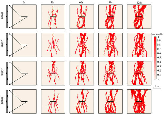
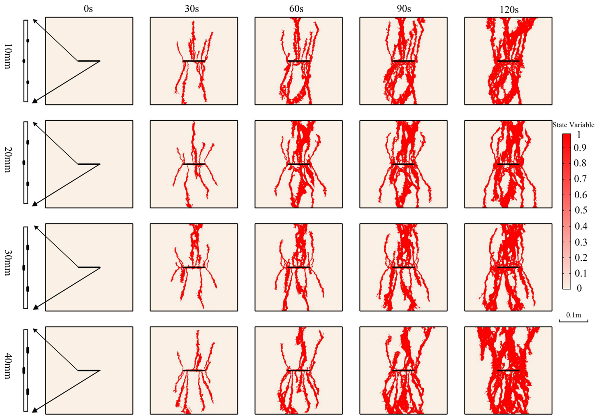
Compared with perforation density, perforation diameter has a more significant influence on fracture propagation (Figure 12). As the perforation diameter increases, the number of fracture initiation sources increases markedly, and the propagation speed and morphological complexity improve significantly; in particular, the fracture propagation range in the x-direction increases accordingly, and the fracture network exhibits a more dispersed multi-branch morphology. The reason is that a larger perforation diameter has a larger stress concentration influence range, which can induce initial damage over a wider range, and at the same time provides a wider initiation channel for the fracture, favoring rapid initiation and multi-directional propagation of fractures, thereby enhancing the effective stimulated volume of fracturing.
Figure 12.
Simulation results of fracturing under different perforation diameters.
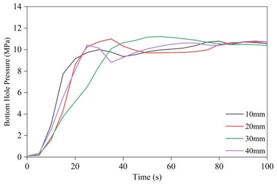
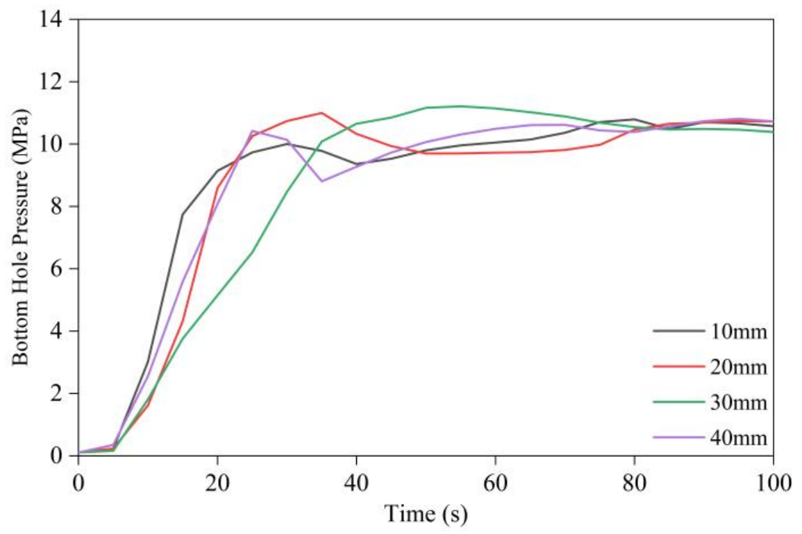
In terms of breakdown pressure, the pressure evolution under the four perforation diameters all exhibit a three-stage characteristic of rapid buildup to initiation, a brief drop, then gradual recovery and stabilization (Figure 13). As the perforation diameter increases, the pressure rise rate in the first stage gradually slows, i.e., the initial pressure accumulation is slower under larger diameters. Under the small diameter (10 mm), the stress concentration coefficient at the perforation tip is high, so the local effective stress more easily reaches the tensile initiation criterion first and the initiation pressure is the lowest; under the medium diameters (20 and 30 mm), the stress concentration effect is relatively weakened and the initiation pressure increases; when the diameter further increases to 40 mm, although the stress concentration is further weakened, the perforation friction is greatly reduced, improving the pressure transmission efficiency at the perforation tip [31], so the initiation pressure drops instead; this part of the explanation is qualitative and is inferred from established perforation-friction theory [31] rather than from explicit friction modeling. In summary, the influence of perforation diameter on breakdown pressure is controlled by local stress concentration within the explicitly modeled mechanisms, while perforation friction provides a plausible complementary explanation. In engineering design, the intermediate unfavorable diameter range should be avoided, and the diameter should be optimized in combination with formation conditions and pumping rate.
Figure 13.
Variation in breakdown pressure under different perforation diameters.
4.3. Influence of Perforation Orientation
Constrained by reservoir heterogeneity, the propagation of hydraulic fractures has a clear directionality. On the one hand, the directional difference in the in situ stress field makes fractures preferentially extend along the maximum principal stress direction [32]; on the other hand, fractures tend to expand along weak structural planes such as natural fractures and bedding planes [33,34]. The relative relationship between the perforation orientation and the dominant fracture propagation direction directly determines the propagation morphology, extension difficulty, and spatial distribution characteristics of the hydraulic fractures. For this purpose, four cases with perforation orientation angles of 0, 30, 60, and 90 degrees relative to the x-axis are set for comparative simulation to clarify the influence of perforation orientation on fracture propagation morphology and breakdown pressure.
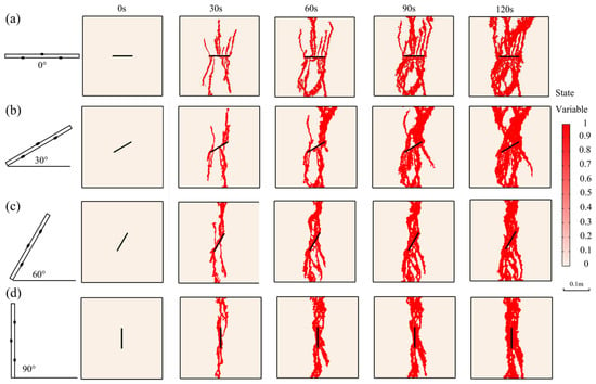
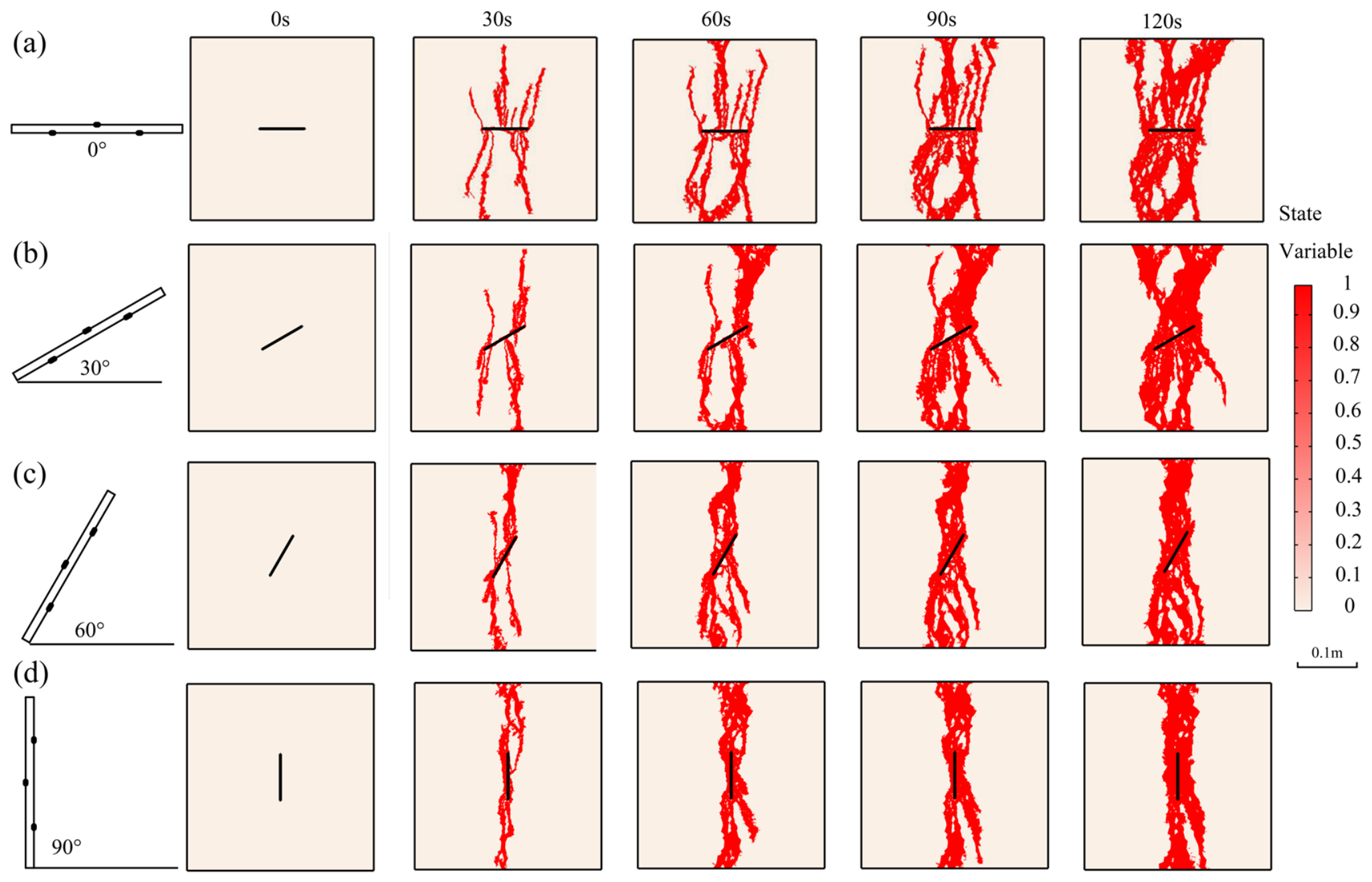
As the perforation orientation angle increases, the fracture propagation speed along the y-direction gradually increases, but the total fracture area and the propagation width along the x-direction decrease significantly, the number of fracture branches decreases, and the network complexity is markedly reduced (Figure 14). Because the maximum principal stress is distributed along the y-direction in the simulation, fractures have a dominant tendency to extend along the y-direction. When the perforation orientation is perpendicular to the maximum principal stress direction, the projection spacing of the perforation initiation points on the x-axis is the largest, so the initiated fractures can hardly converge and connect during propagation along the y-direction, and thus many branch fractures develop in the x-direction, ultimately forming a fracture network with complex morphology and a larger spreading area; as the angle between the perforation orientation and the maximum principal stress direction gradually decreases, the x-axis projection spacing of the initiation points continuously shrinks, and the fractures rapidly converge and connect during propagation, ultimately forming a single main fracture with simple morphology and larger width.
Figure 14.
Simulation results of fracturing under different perforation orientations. (a) angle 0°; (b) angle 30°; (c) angle 60°; (d) angle 90°.
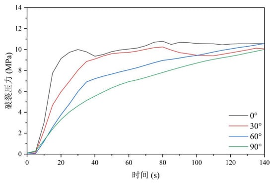
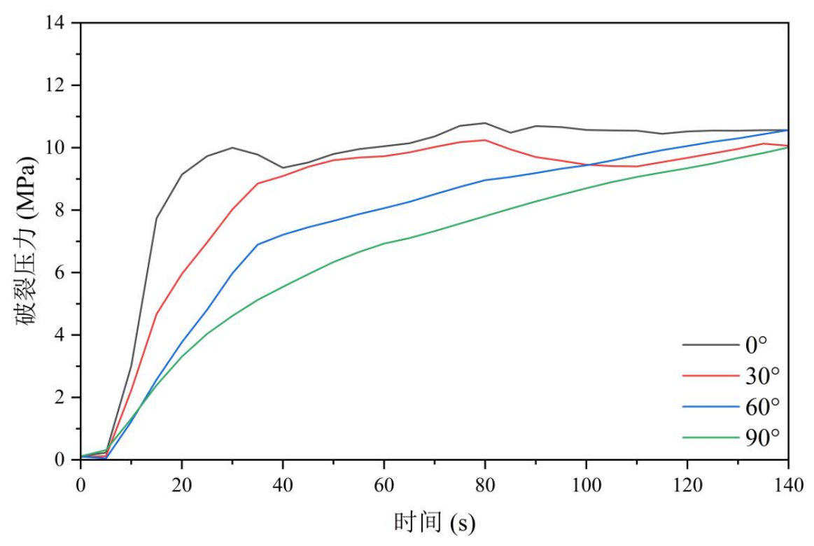
As the perforation orientation angle increases, the difficulty of reservoir fracturing gradually decreases (Figure 15). It is worth noting that when the perforation orientation exceeds 60 degrees, no obvious breakdown pressure feature appears in the formation, and the fracturing curve shows an overall continuous rising trend. The main reason is that under large orientation angles, the projection spacing of the perforation positions in the direction perpendicular to the maximum principal stress is too small, so the perforations can rapidly connect with each other after initiation, thereby significantly reducing the initiation threshold and the difficulty of fracturing stimulation.
Figure 15.
Variation in breakdown pressure under different perforation orientations.
In summary, the perforation orientation has a significant influence on both the fracture propagation morphology and the difficulty of fracturing stimulation in coal reservoirs. It should be noted that this paper only considers the influence of the directional heterogeneity of in situ stress, whereas in actual engineering, the heterogeneity of coal reservoirs is more complex, and weak structural planes such as natural fractures and bedding planes will interfere with fracture propagation [35]. Therefore, the design of perforation orientation should comprehensively consider geological factors such as natural fracture orientation and bedding occurrence.
4.4. Response of Perforation Techniques Under Different Geological Conditions
The in situ stress state, rock strength, and permeability of coal reservoirs are strongly heterogeneous, and the favorable perforation parameters depend on the specific reservoir conditions [13,14,15,36]. To this end, a full combination of perforation orientations (0, 30, 60, and 90 degrees) and perforation densities (4, 8, 12, 16 HPM, holes/m) is designed, giving a total of 16 cases, and systematic simulations are carried out under six reservoir conditions, including two in situ stress combinations, two rock strength combinations, and two permeability levels, with the breakdown pressure as the unified quantitative evaluation index, to investigate the coupling law between reservoir conditions and perforation parameters.
The optimization in this study is carried out quantitatively as follows: for each reservoir condition, the breakdown pressure of each of the 16 perforation combinations is extracted from the simulated bottomhole pressure curve as its first peak value; the combination yielding the minimum breakdown pressure is identified as the most favorable one under this criterion, and the minimum value, the maximum value, and the overall range of the breakdown pressure are then compared among the different reservoir conditions to reveal the response laws. The degree of fracturing stimulation is thus quantified by a single, reproducible index, i.e., the minimum breakdown pressure, which allows direct cross-comparison between cases. It should be emphasized that this index captures the ease of fracture initiation only.
1. Influence of in situ stress state
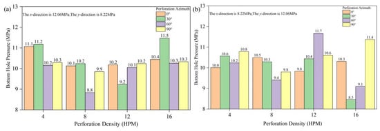
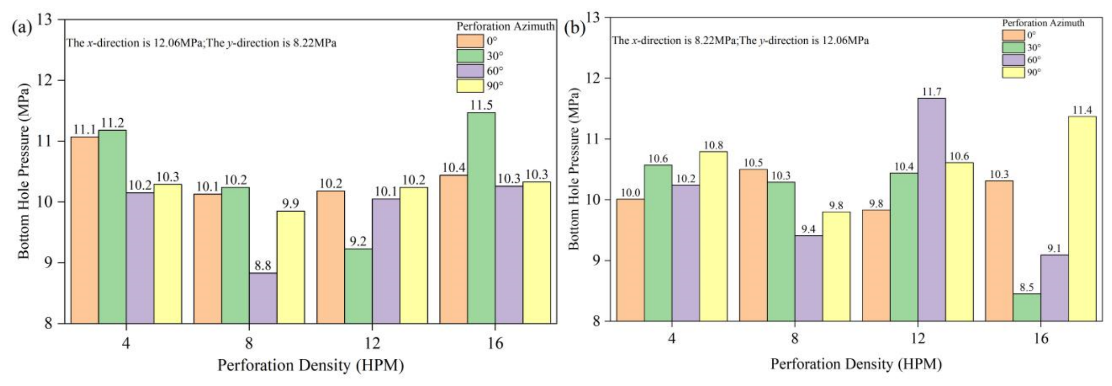
(1) Horizontal stress as the maximum principal stress. When the in situ stress in the x-direction is 12.06 MPa and that in the y-direction is 8.22 MPa, the breakdown pressure of the coal seam ranges from 8.9 to 11.8 MPa (Figure 16a). From the perspective of perforation density, the breakdown pressures of 8 HPM and 12 HPM are generally lower than those of 4 HPM and 16 HPM, indicating that a medium perforation density is favorable for reducing the breakdown pressure. This is because when the density is too low, the initiation sources are insufficient, and when the density is too high, the inter-perforation stress interference intensifies, both of which are unfavorable for smooth fracture initiation.
Figure 16.
Breakdown pressure under different perforation orientations and densities when the horizontal and vertical stresses are the maximum principal stress. (a) the stress of x-direction is 12.06 MPa, and the stress of y-direction is 8.22 MPa; (b) the stress of x-direction is 8.22 MPa, and the stress of y-direction is 12.06 MPa.
From the perspective of perforation orientation, the breakdown pressures at 0 and 30 degrees are generally lower than those at 60 and 90 degrees; that is, the closer the perforation orientation is to the minimum principal stress direction, the stronger the tangential stress concentration around the perforation, and the easier it is to reach the tensile initiation condition, which is consistent with the understanding of classical initiation theory [7,17]. It should be noted that the nonlinearity of parameter coupling makes some individual combinations deviate from the general law: the lowest breakdown pressure (8.9 MPa) occurs in the 8 HPM, 60-degree combination, while the highest value (11.8 MPa) occurs in the 16 HPM, 30-degree combination, the latter possibly being related to the stress shielding effect caused by excessively dense perforation.
(2) Vertical stress as the maximum principal stress. When the in situ stress in the x-direction is 8.22 MPa and that in the y-direction is 12.06 MPa, the breakdown pressure ranges from 8.7 to 11.5 MPa (Figure 16b). Under this stress state, the lowest breakdown pressure (8.7 MPa) occurs in the 16 HPM, 30-degree combination, and the highest value (11.5 MPa) occurs in the 12 HPM, 60-degree combination.
By comparing the two stress states, it can be seen that when the direction of the maximum principal stress changes from horizontal to vertical, the most favorable perforation combination under the minimum-breakdown-pressure criterion changes from “8 HPM, 60-degree” to “16 HPM, 30-degree”, and both the favorable density and orientation change; however, the overall response law of breakdown pressure to perforation orientation remains consistent under the two conditions, i.e., low-angle orientations are generally dominant and the 60-degree orientation generally corresponds to higher breakdown pressure. This result indicates that the in situ stress orientation is the primary controlling factor for perforation orientation optimization, and perforation parameter design must be based on accurate in situ stress testing [13,14].
2. Influence of initial permeability
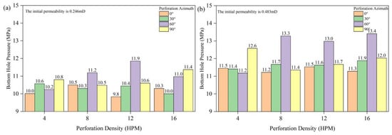
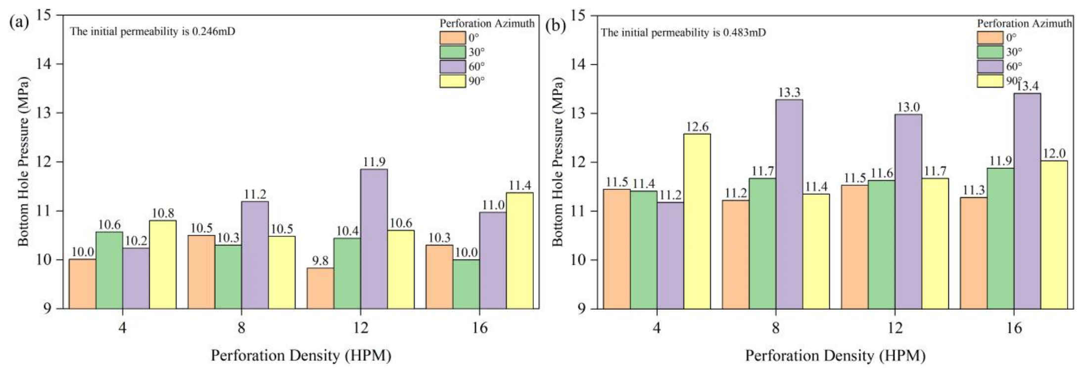
Initial permeability affects the fracturing process mainly through two paths, namely fracturing fluid leak-off and pressure propagation. In low-permeability reservoirs, the leak-off is small and the pore pressure near the perforations accumulates quickly, making it easy to reach the critical initiation condition; in high-permeability reservoirs, the leak-off rate is large and the injected fluid diffuses rapidly along the matrix, diluting the pressure accumulation near the perforations and correspondingly increasing the bottomhole pressure required for initiation. Two permeability levels of 0.246 mD and 0.483 mD are selected for comparison.
Under the low-permeability condition (0.246 mD), the breakdown pressure ranges from 9.5 to 11.8 MPa (Figure 17a): the 0-degree and 30-degree orientations are significantly lower than the 60-degree and 90-degree orientations; the lowest value (9.5 MPa) occurs in the 12 HPM, 30-degree combination, and the highest value (11.8 MPa) occurs in the 12 HPM, 60-degree combination. Under the high-permeability condition (0.483 mD), the breakdown pressure is elevated overall to 11.1–13.2 MPa (Figure 17b): compared with the low-permeability condition, the lower and upper limits increase by 1.6 MPa and 1.4 MPa, respectively, verifying the controlling effect of the leak-off dilution effect; the general law that low-angle orientations are dominant remains unchanged, with the lowest value (11.1 MPa) in the 8 HPM, 30-degree combination and the highest value (13.2 MPa) in the 16 HPM, 60-degree combination.
Figure 17.
Breakdown pressure under different perforation orientations and densities under low- and high-permeability conditions. (a) The initial permeability is 0.246 mD; (b) The initial permeability is 0.483 mD.
Comparison of the two groups of results shows that doubling the initial permeability raises the breakdown pressure of the whole combination by about 1.4–1.6 MPa, making it the most significant factor among the three investigated reservoir factors affecting breakdown pressure; meanwhile, the increase in permeability does not change the general parameter response law that “low-angle orientation + medium density is favorable”. In engineering, for coal seams with relatively high permeability, it is advisable to increase the pumping rate or adopt leak-off control measures to compensate for the pressure loss caused by leak-off.
3. Influence of rock strength
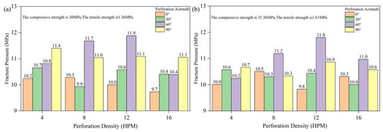
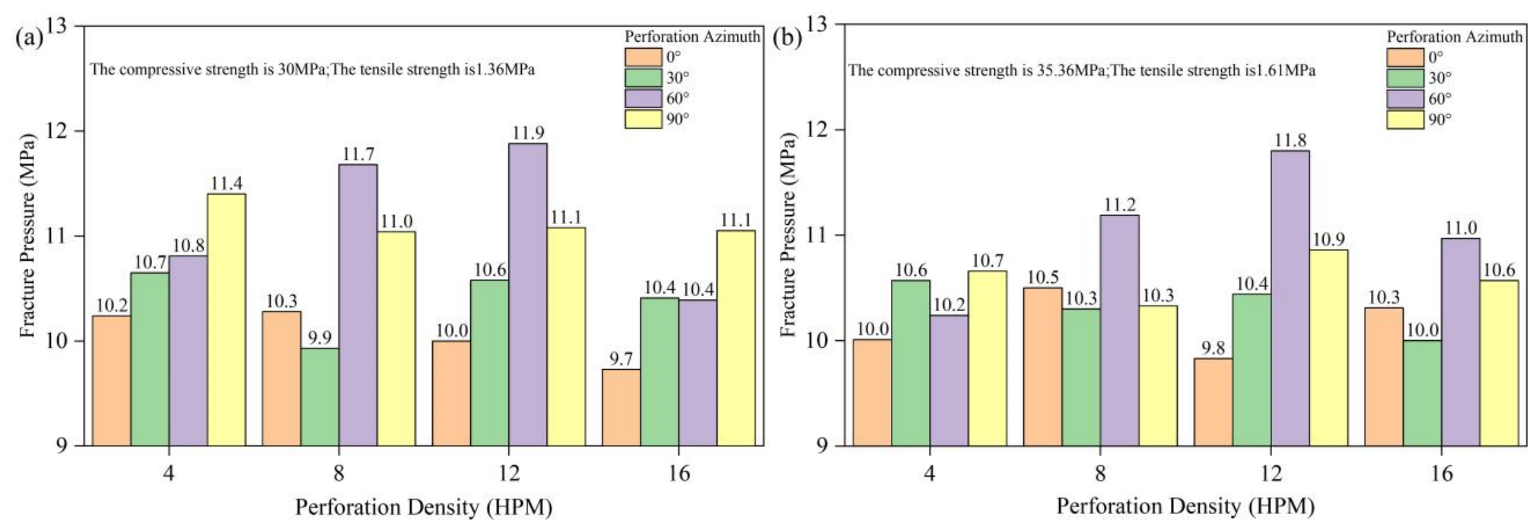
Rock strength (compressive strength and tensile strength) is a key geomechanical parameter controlling fracturing initiation, which determines both the breakdown pressure level required for fracturing and the propagation morphology and mode of fractures. Two strength combinations are selected for comparison: a low-strength group (compressive strength 30 MPa, tensile strength 1.36 MPa) and a high-strength group (compressive strength 35.36 MPa, tensile strength 1.61 MPa).
Under the low-strength group, the breakdown pressure ranges from 9.8 to 11.7 MPa (Figure 18a): the breakdown pressures at 0-degree and 30-degree orientations are significantly lower than those at 60-degree and 90-degree orientations, and low-angle perforation is favorable for stress concentration and fracture initiation; the lowest value (9.8 MPa) occurs in the 8 HPM, 30-degree combination, and the highest value (11.7 MPa) occurs in the 12 HPM, 60-degree combination.
Figure 18.
Breakdown pressure under different perforation orientations and densities under low and high rock strength. (a) The compressive strength is 30 MPa, and the tensile strength is 1.36 MPa; (b) The compressive strength is 35.36 MPa, and the tensile strength is 1.61 MPa.
Under the high-strength group, the breakdown pressure ranges from 9.8 to 11.8 MPa (Figure 18b): the breakdown pressure at the 60-degree orientation is significantly higher than at other angles, indicating that this orientation poses a certain obstacle to fracture propagation; the lowest value (9.8 MPa) occurs in the 12 HPM, 30-degree combination, and the highest value (11.8 MPa) occurs in the 12 HPM, 60-degree combination.
It is worth noting that although the tensile strength of the high-strength group is about 18% higher than that of the low-strength group, its breakdown pressure only rises slightly, and the favorable orientation remains 30 degrees while the favorable density changes from 8 HPM to 12 HPM. The sensitivity of breakdown pressure to rock strength is lower than its sensitivity to in situ stress state and initial permeability. The reason is that initiation is jointly controlled by the effective tensile stress around the perforation and the tensile strength; in a high in situ stress environment, the magnitude of the stress concentration term far exceeds the strength difference term, weakening the influence of the strength variation.
4.5. Design Principles for Perforation Parameter Optimization
The optimization design of perforation parameters for hydraulic fracturing in coal reservoirs can follow the principles below. (1) Orientation-first principle: the perforation orientation is the primary perforation parameter controlling breakdown pressure; low-angle (0-degree and 30-degree) orientations show an obvious pressure-reducing advantage under all reservoir conditions, whereas the 60-degree orientation generally corresponds to the highest breakdown pressure. Orientation optimization should be based on in situ stress orientation testing, preferentially selecting low-angle perforation matching the minimum principal stress direction. (2) Moderate-density principle: when the density is too low, the initiation sources are insufficient and the fracture network complexity is limited; when the density is too high, inter-perforation stress interference and multi-fracture competition intensify, elevating the initiation pressure and increasing the difficulty of operational control. (3) Moderate-diameter principle: the perforation diameter has a more significant influence on fracture propagation than the perforation density, and its effect on initiation pressure is controlled by local stress concentration with a qualitative contribution of perforation friction, showing a non-monotonic characteristic; the intermediate unfavorable diameter range should be avoided in design, and the perforation friction should be checked in combination with the pumping rate. (4) Reservoir-condition adaptation principle: a change in the direction of the maximum principal stress will shift the favorable density-orientation combination, and an increase in permeability will elevate the initiation pressure overall; the design of perforation parameters should be based on personalized optimization using in situ stress testing, rock mechanical experiments, and physical property analysis of the target reservoir; and for coal seams with relatively high permeability, the pumping rate should be increased or leak-off control measures adopted.
5. Discussion
5.1. Boundary-Size Effect
In several of the above simulations, the fractures eventually reach the model boundary, after which the damaged region continues to widen. Because the roller-supported boundaries confine the stress and pore-pressure fields, this post-breakdown widening is inevitably influenced, to some extent, by the finite model size. To assess this boundary-size effect, the evolution before boundary contact was examined separately: in all cases, the initiation position, initiation pressure, and early propagation direction are governed by the near-field stress concentration and the far-field stress difference, and the fracture length at boundary contact is much larger than the injection-port diameter, indicating that the initiation and early-propagation stages, which are the stages of primary interest in this study, are essentially independent of the model size. The post-contact widening should therefore be interpreted qualitatively, as the tendency of a fracture to grow in width when its length growth is arrested by a natural barrier (e.g., a lithological interface), rather than as an exact prediction of the field-scale fracture width.
5.2. Limitations and Future Work
It should be noted that the conclusions of this study are mainly based on numerical simulation results and have certain limitations. First, the model adopts a two-dimensional plane-strain assumption and simplifies natural fractures in a regularized manner, making it difficult to fully reproduce the three-dimensional spatial distribution and heterogeneous characteristics of the natural fracture network in real coal reservoirs. Second, the model parameters are taken from laboratory experiments and typical values in the literature, which differ from the heterogeneity and complex in situ stress environment of actual reservoirs. Third, the simulation does not fully consider the influence of factors such as fracturing fluid leak-off, temperature effects, and gas–water two-phase flow. Therefore, the conclusions obtained in this paper are mainly qualitative, and the quantitative results still need to be further verified and improved in combination with field fracturing operations, microseismic monitoring, and other data.
Based on the above discussion, future work is recommended in the following directions: (1) extending the present two-dimensional model to three dimensions and incorporating stochastic discrete-fracture networks to better represent the heterogeneous natural-fracture system of real coal reservoirs; (2) explicitly incorporating perforation-entry friction, wellbore storage, fracturing-fluid leak-off, thermal effects, and gas–water two-phase flow into the coupled model, so that the perforation-diameter effect and the pressure response can be quantified more rigorously; (3) enlarging the model domain and carrying out systematic model-size independence tests to quantify the boundary-size effect; and (4) validating and calibrating the model with field fracturing data and microseismic monitoring, and coupling the model with multi-objective optimization that additionally considers fracture complexity, stimulated reservoir volume, pressure losses, and operational constraints.
6. Conclusions
Based on the damage–seepage coupled numerical simulation and the systematic analysis of perforation parameters and reservoir conditions, the following main conclusions are obtained:
- (1)
- The reservoir fracturing process exhibits staged evolution characteristics, and the secondary breakdown pressure (about 22 MPa) is approximately 15% lower than the initial breakdown pressure (about 26 MPa); after the fractures reach the barrier boundary, they turn to expand in the width direction, and the existence of the barrier boundary is favorable for forming a larger fracture width. Multiple perforations along the horizontal wellbore can form multiple transverse fractures across the wellbore, and the fractures initiate from the perforations with a feather-like distribution; compared with vertical wells, horizontal well fracturing is favorable for improving fracture network complexity and reservoir stimulated volume.
- (2)
- Perforation parameters significantly affect the fracturing performance. When the perforation density is too low, the initiation sources are insufficient and the fracture network complexity is limited; when it is too high, the inter-perforation stress interference intensifies and the breakdown pressure rises. The influence of the perforation diameter on the initiation pressure is controlled by local stress concentration, with perforation friction as a qualitative complementary factor, and the intermediate unfavorable diameter range should be avoided. Low-angle perforation orientation is favorable for reducing the initiation pressure, and no obvious breakdown pressure feature appears in the formation under large-angle orientations.
- (3)
- Reservoir geological conditions control the breakdown difficulty and the parameter response law. Natural fractures slightly delay the initial initiation time, but significantly accelerate the post-breakdown propagation rate, widen the fractured region, and improve the reservoir permeability; the sensitivity of breakdown pressure to reservoir conditions decreases in the order of initial permeability, in situ stress orientation, and rock strength, and a change in the direction of the maximum principal stress will shift the optimal perforation density and orientation combination.
- (4)
- The optimization of hydraulic fracturing perforation parameters in coal reservoirs should follow the principles of “orientation first, moderate density and diameter, and reservoir-condition adaptation”, preferentially selecting low-angle perforation matching the minimum principal stress direction, and carrying out optimization in combination with in situ stress testing, rock mechanical experiments, and physical property analysis of the target reservoir. The identified favorable combinations are optimal under the minimum-breakdown-pressure criterion; in practical design, they should be further weighed against fracture complexity, stimulated reservoir volume, pressure losses, and operational constraints.
Author Contributions
Conceptualization, X.F.; methodology, B.X.; formal analysis, B.X.; writing—original draft preparation, B.X. and Z.X.; writing—review and editing, Z.X., Y.M., S.W. and Z.Y. All authors have read and agreed to the published version of the manuscript.
Funding
This research was funded by the 2023 Xinjiang Uygur Autonomous Region Major Science and Technology Special Project, grant number 2023A01004-3.
Data Availability Statement
The original contributions presented in this study are included in the article. Further inquiries can be directed to the corresponding author.
Conflicts of Interest
Authors Baolei Xie, Zhiwen Xue, Yongqiang Ma, Shuchun Wu and Zongshen Yang were employed by the Second Exploration Team, Jiangsu Coal Geology Bureau. The remaining author declares that the research was conducted in the absence of any commercial or financial relationships that could be construed as potential conflicts of interest.
References
- Hubbert, M.K.; Willis, D.G. Mechanics of hydraulic fracturing. Trans. AIME 1957, 210, 153–163. [Google Scholar] [CrossRef] [Scilit]
- Haimson, B.; Fairhurst, C. Initiation and extension of hydraulic fractures in rocks. SPE J. 1967, 7, 310–318. [Google Scholar] [CrossRef] [Scilit]
- Yao, P.; Zhang, J.; Lv, D.; Vandeginste, V.; Chang, X.; Zhang, X.; Wang, D.; Han, S.; Liu, Y. Effect of water occurrence in coal reservoirs on the production capacity of coalbed methane by using NMR simulation technology and production capacity simulation. Geoenergy Sci. Eng. 2024, 243, 213353. [Google Scholar] [CrossRef] [Scilit]
- Gao, X.; Wang, Y.; Ni, X.; Tao, C.; Zhao, S. Mechanical properties of deep coal and rock in Linxing area and its influences on fracturing of deep coal reservoir. J. China Coal Soc. 2020, 45, 912–921. [Google Scholar]
- Huang, Z.; Li, Z.; Li, G.; Yang, R.; Mei, Y.; Niu, J.; Li, Z.; Wu, C.; Wen, H.; Cong, R. Oriented and sand control hydra-jet fracturing in coalbed methane horizontal wells and field applications. J. China Coal Soc. 2022, 47, 2687–2697. [Google Scholar] [CrossRef]
- Miao, H.; Veerle, V.; Zhang, J.; Chen, S.; Chang, X.; Du, Y.; Wang, Y.; Wei, C.; Luo, J.; Quan, F.; et al. Control mechanism of pressure drop rate on coalbed methane productivity by using production data and physical simulation technology. Fuel 2025, 406, 137060. [Google Scholar] [CrossRef] [Scilit]
- Hossain, M.M.; Rahman, M.K.; Rahman, S.S. Hydraulic fracture initiation and propagation: Role of wellbore trajectory, perforation and stress regimes. J. Pet. Sci. Eng. 2000, 27, 129–149. [Google Scholar] [CrossRef] [Scilit]
- Ren, L.; Zhao, J.; Hu, Y.; Ran, Y. Numerical calculation of rock breakdown pressure during hydraulic fracturing process. Chin. J. Rock Mech. Eng. 2009, 28, 3417–3422. [Google Scholar] [CrossRef]
- Zhu, W.; Tang, C. Numerical simulation on shear fracture process of concrete using meso-level elements. Constr. Build. Mater. 2002, 16, 453–463. [Google Scholar] [CrossRef] [Scilit]
- Cheng, L.; Luo, Z.; Xie, Y.; Zhang, Z.; Yang, D. Numerical simulation and analysis of damage evolution and seepage of fractured rock mass under hydromechanical coupling. Comput. Geotech. 2023, 155, 105244. [Google Scholar] [CrossRef] [Scilit]
- Rutqvist, J.; Wu, Y.; Tsang, C.; Bodvarsson, G. A modeling approach for analysis of coupled multiphase fluid flow, heat transfer, and deformation in fractured porous rock. Int. J. Rock Mech. Min. Sci. 2002, 39, 429–442. [Google Scholar] [CrossRef] [Scilit]
- Zhang, W.; Wang, C.; Guo, T.; Yang, R.; Li, X.; Zhang, Q. Study on the cracking mechanism of hydraulic and supercritical CO2 fracturing. Energy 2021, 221, 119886. [Google Scholar] [CrossRef] [Scilit]
- Tang, S.; Zhu, B.; Yan, Z. Effect of crustal stress on hydraulic fracturing in coalbed methane wells. J. China Coal Soc. 2011, 36, 65–69. [Google Scholar] [CrossRef]
- Zhu, B.; Tang, S.; Yan, Z.; Zhang, J. Effects of crustal stresses and natural fractures on fracture pressure of coal reservoirs. J. China Coal Soc. 2009, 34, 1199–1202. [Google Scholar] [CrossRef]
- Huang, S.; Liu, D.; Yao, Y.; Cai, Y.; Xie, Y. Natural fractures initiation and fracture type prediction in coalbed methane reservoirs. J. Nat. Gas. Sci. Eng. 2017, 43, 69–80. [Google Scholar] [CrossRef] [Scilit]
- Tan, P.; Jin, Y.; Hou, B.; Han, K.; Zhou, Y.; Meng, S. Experimental investigation on fracture initiation and non-planar propagation of hydraulic fracturing. Pet. Explor. Dev. 2017, 44, 470–476. [Google Scholar] [CrossRef] [Scilit]
- Liu, G.; Li, Y. Initial perforating azimuth angle considering stress of stratum. Acta Pet. Sin. 2001, 22, 105–108. [Google Scholar] [CrossRef]
- Li, H.; Wang, Y.; Li, H.; Ge, Y. Perforation optimization design method for prefracturing wells. Nat. Gas. Ind. 1998, 18, 43–46. [Google Scholar]
- Jin, Y.; Zhang, X.; Chen, M. Initiation pressure models for hydraulic fracturing of vertical wells in naturally fractured formation. Acta Pet. Sin. 2005, 26, 113–114, 118. [Google Scholar] [CrossRef]
- Labuz, J.F.; Zang, A. Mohr-Coulomb failure criterion. Rock Mech. Rock Eng. 2012, 45, 975–979. [Google Scholar] [CrossRef] [Scilit]
- Guo, X.; Jin, Y.; Miu, T.; Wei, S.; Xia, Y.; Tang, J. Investigation of the time-dependent and dynamic geomechanical behaviors induced by depressurization in natural gas hydrate-bearing sediments based on a poro-elasto-viscoplastic-dynamic model. Int. J. Rock Mech. Min. Sci. 2026, 197, 106357. [Google Scholar] [CrossRef] [Scilit]
- Fairhurst, C. On the validity of the ‘Brazilian’ test for brittle materials. Int. J. Rock Mech. Min. Sci. Geomech. Abstr. 1964, 1, 535–546. [Google Scholar] [CrossRef] [Scilit]
- Bieniawski, Z.T.; Hawkes, I. Suggested methods for determining tensile strength of rock materials. Int. J. Rock Mech. Min. Sci. Geomech. Abstr. 1978, 15, 99–103. [Google Scholar] [CrossRef] [Scilit]
- Yew, C.H.; Weng, X. Mechanics of Hydraulic Fracturing, 2nd ed.; Gulf Professional Publishing: Houston, TX, USA, 2014. [Google Scholar]
- Detournay, E.; Cheng, A.H.-D. Fundamentals of poroelasticity. In Comprehensive Rock Engineering; Hudson, J.A., Ed.; Pergamon Press: Oxford, UK, 1993; Volume 2, pp. 113–171. [Google Scholar]
- Wu, K.; Olson, J.E. Mechanics analysis of interaction between hydraulic and natural fractures in shale reservoirs. In Proceedings of the Unconventional Resources Technology Conference, Denver, CO, USA, 25–27 August 2014. [Google Scholar] [CrossRef] [Scilit]
- Warpinski, N.R.; Teufel, L.W. Influence of geologic discontinuities on hydraulic fracture propagation. J. Pet. Technol. 1987, 39, 209–220. [Google Scholar] [CrossRef] [Scilit]
- Blanton, T.L. An experimental study of interaction between hydraulically induced and pre-existing fractures. In Proceedings of the SPE Unconventional Gas Recovery Symposium, Pittsburgh, PA, USA, 16–18 May 1982. [Google Scholar] [CrossRef]
- Surjaatmadja, J.B.; Grundmann, S.R.; McDaniel, B.; Deeg, W.F.J.; Brumley, J.L.; Swor, L.C. Hydrajet fracturing: An effective method for placing many fractures in openhole horizontal wells. In Proceedings of the SPE International Conference on Horizontal Well Technology, Calgary, AB, Canada, 1–4 November 1998. [Google Scholar] [CrossRef]
- Lagrone, K.W.; Rasmussen, J.W. A new development in completion methods—The limited entry technique. J. Pet. Technol. 1963, 15, 695–702. [Google Scholar] [CrossRef] [Scilit]
- Crump, J.B.; Conway, M.W. Effects of perforation-entry friction on bottomhole treating analysis. J. Pet. Technol. 1988, 40, 1041–1048. [Google Scholar] [CrossRef] [Scilit]
- Balme, M.R.; Rocchi, V.; Jones, C.; Sammonds, P.R.; Meredith, P.G.; Boon, S. Fracture toughness measurements on igneous rocks using a high-pressure, high-temperature rock fracture mechanics cell. J. Volcanol. Geotherm. Res. 2004, 132, 159–172. [Google Scholar] [CrossRef] [Scilit]
- Fan, T.; Zhang, G. Laboratory investigation of hydraulic fracture networks in formations with continuous orthogonal fractures. Energy 2014, 74, 164–173. [Google Scholar] [CrossRef] [Scilit]
- Jiang, B.; Qu, Z.; Wang, G.G.X.; Li, M. Effects of structural deformation on formation of coalbed methane reservoirs in Huaibei coalfield, China. Int. J. Coal Geol. 2010, 82, 175–183. [Google Scholar] [CrossRef] [Scilit]
- Sun, C.; Zheng, H.; Liu, W.; Lu, W. Numerical simulation analysis of vertical propagation of hydraulic fracture in bedding plane. Eng. Fract. Mech. 2020, 232, 107056. [Google Scholar] [CrossRef] [Scilit]
- Huang, S.; Yao, Y.; Cui, J.; Zhang, J.; Li, J. Numerical simulation study on influence factors of hydraulic fracturing pressure in coal reservoir. Coal Sci. Technol. 2015, 43, 123–126. [Google Scholar] [CrossRef]

Disclaimer/Publisher’s Note: The statements, opinions and data contained in all publications are solely those of the individual author(s) and contributor(s) and not of MDPI and/or the editor(s). MDPI and/or the editor(s) disclaim responsibility for any injury to people or property resulting from any ideas, methods, instructions or products referred to in the content. |
© 2026 by the authors. Licensee MDPI, Basel, Switzerland. This article is an open access article distributed under the terms and conditions of the Creative Commons Attribution (CC BY) license.