Article

Azeotropic and Extractive Distillation for Bio-Ethanol Dehydration: Process Design, Simulation, and Cost Analysis

by
Mihaela Neagu
* and
Marilena Pricop-Nicolae
Department of Petroleum Processing and Environmental Engineering, Faculty of Petroleum Refining and Petrochemistry, Petroleum-Gas University of Ploiesti, 39. Bucuresti Blvd, 100680 Ploiesti, Romania
*
Author to whom correspondence should be addressed.
Processes 2025, 13(11), 3634; https://doi.org/10.3390/pr13113634
Submission received: 25 August 2025 / Revised: 31 October 2025 / Accepted: 5 November 2025 / Published: 10 November 2025
(This article belongs to the Section Separation Processes)

Abstract

The global demand for sustainable fuels has intensified interest in bioethanol production. Conventional distillation is limited by the ethanol–water azeotrope at ~95.8 wt.% ethanol, necessitating alternative separation methods. This study presents a technical and economic comparison of bioethanol dehydration via azeotropic distillation using cyclopentane as a novel entrainer and extractive distillation with ethylene glycol. Steady-state simulations were conducted in AVEVA PRO/II v.2024 under identical feed conditions, targeting a final ethanol purity of 99.94 wt.%. Cyclopentane proved effective, producing high-purity ethanol and water streams free of entrainer, while ethylene glycol also achieved comparable purity. Economically, the azeotropic process required ~36.5% higher capital investment due to taller columns, larger condensers, and the entrainer cost, resulting in a total annual cost (TAC) ~25.6% higher than the extractive process. Nevertheless, the azeotropic configuration offers lower operating costs, relying solely on low-pressure steam, and residual cyclopentane in ethanol does not compromise fuel quality, unlike ethylene glycol. The study demonstrates that cyclopentane-based azeotropic distillation is technically viable for fuel-grade ethanol production and provides a quantitative framework for evaluating entrainer selection and process economics, particularly in regions where cyclopentane is available or cost-effective.

1. Introduction

The demand for anhydrous bioethanol has increased significantly in response to environmental policies that promote its use as a bio-component in gasoline blends. Globally, there is a growing trend toward replacing classic refineries with bio-refineries. Bio-refineries play a fundamental role in the transition to a circular economy by reducing dependence on fossil fuels by converting renewable biomass into biofuels and bioenergy, while also contributing to climate change mitigation [1]. In addition, they reduce the waste producing value-added products [2,3,4], such as: platform chemicals (e.g., succinic acid [5]), bio-based polymers and materials [6], fine chemicals, and other bio-derived intermediates that have applications in plastics, coatings, solvents, and pharmaceuticals [7].
Depending on the renewable feedstock, bioethanol production is a complex and time-consuming process that involves several stages, of which three are essential: raw material pretreatment, fermentation, and ethanol dehydration [8,9]. Ethanol must be dehydrated to prevent phase separation. The dehydration stage is particularly energy-intensive, since the formation of the ethanol-water azeotrope limits the efficiency of conventional distillation. Therefore, advanced technological solutions and complex process configurations are necessary to produce ethanol with sufficient purity for its use as a biofuel [10].
Extractive distillation (ED) is a well-known industrial technique for separating binary or ternary azeotropic mixtures into their pure components. In this process, the relative volatility of the mixture is increased by the addition of a solvent, which must be completely miscible and should not introduce new azeotropes. A fundamental application of ED is ethanol dehydration in the bioethanol fuel industry, where heavy solvents such as ethylene glycol or glycerol are commonly employed [11,12]. Although alternative technologies, such as azeotropic distillation [10,13], pervaporation [14], adsorption on molecular sieves [15], or hybrid technologies [16], are available for the dehydration of ethanol, ED remains the preferred option for large-scale production due to its economic and operational advantages [12]. In recent decades, numerous studies have explored advanced techniques to enhance alcohol dehydration through extractive distillation. These include vapor recompression distillation followed by salt-based extractive distillation, single-wall extractive distillation column assisted by a heat pump, three-wall extractive distillation, distillation integrated with vapor permeation, distillation followed by pressure swing adsorption, etc. [16,17,18,19]. Although many of these technologies have shown promising performance, their applicability in the bioethanol dehydration industry remains limited due to economic, operational, and integration challenges [16,20,21,22].
The conventional extractive distillation (ED) process consists of two columns. The first column is fed with the ethanol-water azeotrope, while the solvent is introduced at the top. The solvent enhances the separation of water from the azeotrope. The bottom product of this column is then directed to the second column, which is responsible for the solvent regeneration before its recirculation back to the first column. To minimize energy consumption and economic costs associated with the conventional extractive distillation (ED) process, the excess water from the fermentation broth can be removed using a preconcentration column (PC). In this column, the distillate is the ethanol-water azeotrope itself, while the bottom product is excess water. The azeotrope obtained in the PC is then fed to the extractive distillation column, as described earlier. This innovative approach has allowed researchers to reduce overall energy consumption in the process and to investigate the heat integration of the PC with the ED column and/or the regeneration column [23,24,25,26].
Azeotropic distillation is an inherently more complex process than extractive distillation. In this process, an entrainer is added to the alcohol-water azeotrope to form a new binary or ternary heteroazeotrope, which is then separated into vapor streams at the top of the columns. The process typically involves two distillation columns, a condenser, and a two-phase separator vessel with immiscible liquid phases: an organic phase rich in entrainer and alcohol, and an aqueous phase. The bottom product of the first column is dehydrated alcohol. The aqueous phase feeds the second column. Typically, the entrainer is introduced into the process in the separator vessel or in the feed of the first column, and then it is continuously recycled throughout the process. Although it achieves a high level of alcohol dehydration, azeotropic distillation requires substantial energy consumption and large flow rates of entrainer, resulting in high operating costs.
Few studies in the literature have evaluated the performance of azeotropic distillation for ethanol dehydration, likely due to the complexity of the process. Over time, only a few entrainers have been tested, including benzene, pentane, cyclohexane, hexane, heptane, isooctane, and gasoline [27,28,29]. Among these, benzene and cyclohexane have traditionally been used most extensively on an industrial scale [30,31]. However, the identification of benzene as a carcinogen has led to its replacement with toluene. Nowadays, process simulators play an essential role in researching and optimizing bioethanol dehydration processes, whether by azeotropic or extractive distillation, utilizing either single solvents, single entrainers, or mixtures [32,33,34,35,36,37]. Batista et al. [32] investigated a typical bioethanol distillation process using an alcoholic wine with 19 components. They validated the simulation results against experimental data collected from a sugar factory in Brazil, through simulations performed in Aspen Plus. The study focused on bioethanol concentration, ethanol recovery, energy consumption, and ethanol losses. Through two optimization approaches, the simulation successfully reproduced the behavior of a real bioethanol distillation plant, and the optimal operating conditions ensured bioethanol production in compliance with the legislation, with low steam consumption and high ethanol recovery. The composition of bioethanol, obtained through simulation under optimal conditions, was compared with the specifications for bioethanol fuel and other high-purity ethanol products.
Miranda et al. [35] studied the performance of extractive and azeotropic distillation processes, using ethylene glycol and cyclohexane as solvents, respectively, for the production of anhydrous ethanol by simulation in Aspen Plus™. For both processes, the feed rate was 100 kmol/h, and the ethanol/water mixture had the composition of the azeotrope at a pressure of 1 bar. The purity of anhydrous ethanol obtained by extractive distillation was 99.50 mol%, and 99.99 mol% by azeotropic distillation, i.e., high-grade purities required by international standards (ASTM D4806, EN 15376, and ANP 36 [38]) for use as a biocomponent in gasolines. However, extractive distillation consumed over 2.4 times less energy in columns’ reboilers compared to the energy required in azeotropic distillation, demonstrating that extractive distillation is the most economical option, even though azeotropic distillation achieved a higher purity of anhydrous ethanol.
Sánchez-Correa et al. [12] present three process configurations for ethanol dehydration by extractive distillation with ethylene glycol: the classical two-column sequence, the thermally coupled sequence with a prefractionator, and the thermally coupled sequence with a side rectifier. The paper focuses on finding a set of specifications for which the model equations yield a unique solution when starting from multiple input variants while obtaining the same overall product purities for ethanol and water. The authors introduce a new concept for calculating the minimum energy consumption and show that the results can also be applied to extractive distillation processes with dividing wall columns (DWC). Calculations were carried out in the Aspen Plus V10® simulator.
Nicolae and Fendu [37] studied the use of dipropylene glycol (DPG) as an extractant for ethanol anhydrization. Vapor-liquid equilibrium (VLE) data for the binary ethanol + DPG system were determined experimentally and regressed using the Non-Random Two Liquid (NRTL) and Universal Quasi-Chemical (UNIQUAC) thermodynamic models in the PRO/II 2020 simulation software. Then, the binary interaction parameters obtained from the regression were used to simulate the separation of water from ethanol by extractive distillation with DPG. A series of simulations was performed for two process variants: the first variant without heat recovery, and a second variant in which the heat of the hot streams from the process flow diagram (PFD) is recovered using three heat exchangers. It was found that the process variant with heat recovery leads to a specific consumption of 7.53 MJ/kg of anhydrous ethanol, a value lower than those reported by other researchers for similar processes.
Fattahi et al. [36] studied the separation of an ethanol/water mixture (87 wt.%) by simulation, using azeotropic distillation with cyclohexane, in the Aspen Plus© environment. The authors made several attempts to find the best process conditions under which ultra-pure ethanol (99.95 wt.%) can be produced using a system consisting of one column for ethanol dehydration and a second for entrainer recovery. The effect of critical process variables, such as the number of trays in the columns and the feed-tray positions, on the total capital cost was also investigated.
This study presents the design, simulation, and economic comparison of two bioethanol dehydration processes: azeotropic distillation using cyclopentane and extractive distillation using ethylene glycol. Our main objective is to evaluate the feasibility of cyclopentane as a novel entrainer and to demonstrate its effectiveness. In contrast, previous studies have employed other entrainers such as benzene, pentane, cyclohexane, hexane, heptane, isooctane, and gasoline. To establish the novelty of this proposed entrainer, we searched the literature and found no other studies regarding the use of cyclopentane as an entrainer for ethanol dehydration. The goal of dehydration is to obtain ethanol with a purity of 99.94 wt.%, suitable for use as a biocomponent in eco-friendly fuels. Both processes have produced anhydrous ethanol with purity exceeding the requirements of EN 15376: Brussels, Belgium and ASTM D4806: Pennsylvania, USA standards [39,40], as corroborated by other studies [11,13,35,37]. However, during transportation, pumping, handling, storage, and blending stages, there is a risk of accumulating several hundred to thousands of parts per million (ppm) of water, which may compromise its suitability for fuel blending. Also, in both processes under study, we aim for the wastewater streams to contain less than 1000 ppm by weight ethanol and not to contain entrainer or solvent, to comply with environmental regulations concerning the maximum allowable pollutant concentrations in municipal and industrial wastewater, and make them suitable for wastewater treatment facilities [41]. To configure these processes and determine the optimal operating parameters for each unit, we performed steady-state simulations, using AVEVA PRO/II v.2024 software [42]. Finally, to evaluate the economic feasibility of each proposed process and compare them, we calculated the total annual cost (TAC) to select the most suitable one.

2. Methodology

In this section, we present the design methodology for a bioethanol dehydration process implemented via two approaches: azeotropic distillation using cyclopentane as an entrainer, and extractive distillation employing ethylene glycol as the solvent. To configure these processes and determine the optimal operating parameters for each unit, we performed steady-state simulations using AVEVA PRO/II v.2024 software. We applied the Chemdist algorithm to solve rigorous mass and energy balances as well as phase-equilibrium calculations across all columns. The thermodynamics, including vapor-liquid/liquid–liquid phase equilibria, were modeled using the NRTL thermodynamic fluid package coupled with the UNIFAC (UNIversal Functional-group Activity Coefficients) fluid package. The NRTL (Non-Random Two-Liquid) model is recommended for application to strongly non-ideal mixtures and partially miscible systems. In our work, the resulting thermodynamic system comprises the following binary mixtures: ethanol/water, ethanol/ethylene glycol, water/ethylene glycol, ethanol/cyclopentane, and water/cyclopentane. To accurately represent the vapor–liquid and vapor–liquid–liquid phase equilibria for each binary mixture, the corresponding interaction parameters must be known. The NRTL model is a liquid-activity model characterized by eight binary interaction parameters aij, aji, bij, bji, cij, cji, α , β , where i, j denote each of the four components considered. The ability of this activity-coefficient model to correctly and comprehensively describe the vapor–liquid equilibrium (VLE) and vapor–liquid–liquid equilibrium (VLLE) thermodynamic behavior of the binary systems involved in the mixture depends largely on the availability of binary interaction parameters. The PRO/II software package includes a database of interaction parameters obtained from experimental data, which is frequently updated. For all of the binary systems in the mixtures involved in this work, VLE and VLLE interaction parameters for the NRTL model are available in the AVEVA PRO/II database. The temperature-dependent UNIFAC-Lyngby group-contribution model was added to contribute solely to the calculation of certain mixture properties of the streams involved in the two investigated processes.
The operation parameters in the two proposed flowsheets were established after many variants of simulations were achieved, varying the number of trays in the columns, the reflux ratio, and the feed stage for each column, until the best results (i.e., reboiler and condenser duty and purities of the ethanol and water were obtained. For the entire iterative procedure, more details are provided in the Supplementary Material and in the results presented in Tables S1–S14.

2.1. Proposed Flowsheet for Azeotropic Distillation Process

The proposed process for producing anhydrous ethanol by azeotropic distillation with cyclopentane (CP) consists of three steps: a preconcentration column (PC), an ethanol dehydration column (C1), and a water separation column (C2), as shown in Figure 1.
In the case of a binary ethanol-water azeotropic mixture, the CP entrainer facilitates the separation by forming a new binary azeotrope with ethanol (at 44.7 °C and 7.5 wt.% ethanol, at atmospheric pressure [43,44]) with a minimum boiling point lower than the ethanol-water azeotrope (at 78.2 °C and 95.8 wt.% ethanol, at atmospheric pressure), which can be then separated at the top of the column (C1). The CP is initially introduced into the separator vessel and is continuously recirculated within the system. Therefore, the process typically consists of two columns, a condenser and a two-phase separator vessel shared by both columns. The first column (C1) is fed with the binary ethanol-water azeotrope and the organic phase (OP) from the separator vessel. At the top of this column, a vapor stream containing the new azeotrope formed between the CP and ethanol is obtained, while dehydrated alcohol is collected at the bottom. The vapors at the top are completely condensed, and the resulting liquid separates into two liquid phases within the common vessel. The aqueous phase (AP) from the vessel is fed into the second column (C2). At the top of this column, a vapor stream is produced, which condenses together with the vapor stream from the first column. The bottom product of the second column is water. The operating conditions of columns PC, C1, and C2 are detailed in Table 1.
The first purpose of this process is to produce an ethanol stream with a minimum concentration of 99.91 wt.%. Bioethanol must have a purity equal to or higher than 99.0–99.8 wt.%, according to the international standards [11]. The second purpose is to obtain water streams from the bottom of the PC and C2 columns containing no more than 1000 ppm by weight of ethanol.
Cyclopentane is a highly flammable volatile organic compound (VOC) with a flash point of approximately −49 °C and an auto-ignition temperature near 380 °C. Any vapor release may create an explosive atmosphere if mixed with air within its flammable limits (1.1–8.7 vol.%) [45]. Therefore, process design must ensure minimal solvent losses and effective vapor control. From an environmental perspective, cyclopentane has a low toxicity and negligible ozone-depletion potential, but it contributes to photochemical smog formation and is regulated as a VOC in both the European Union and the United States [46]. Its global warming potential (GWP ≈ 11) is significantly lower than that of halogenated hydrocarbons, yet minimizing emissions remains a critical sustainability objective [47]. These properties necessitate a comprehensive safety-oriented design approach for any industrial implementation [48,49]. At the industrial level, the process can be rendered safe and technically scalable through the following design strategies: closed-loop entrainer recovery, inert atmosphere operation, explosion-proof design and instrumentation, process control and interlocks, and hazard analysis and operational procedures. While the inclusion of these systems slightly increases the capital and operational expenditures compared to non-flammable entrainers, the additional cost remains moderate when considering the solvent’s low price, high recovery rate, and process simplicity. The cyclopentane-based azeotropic distillation process is technically scalable and industrially viable, provided that appropriate safety engineering and process control measures are incorporated into the design.

2.2. Proposed Flowsheet for Extractive Distillation Process

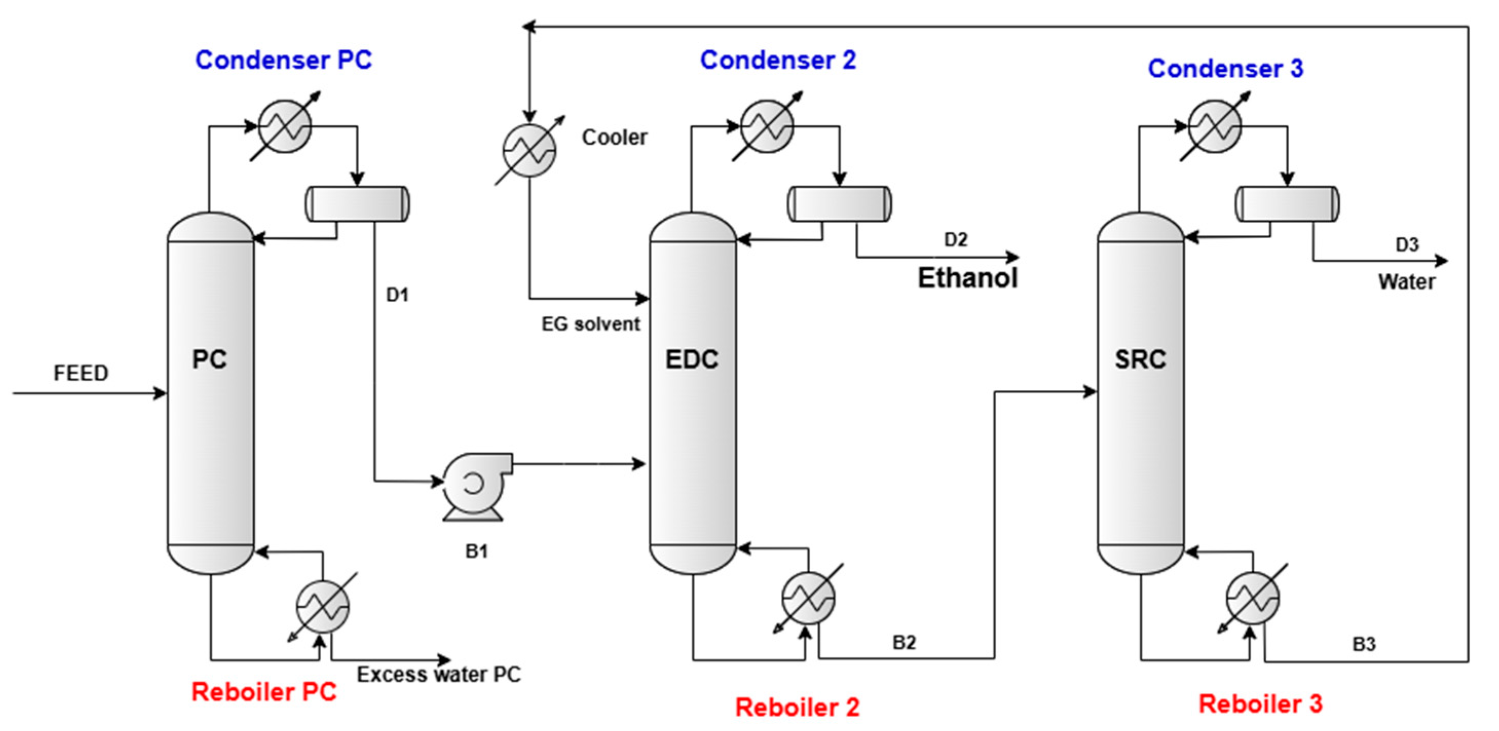
To simulate the ethanol dehydration process via extractive distillation using ethylene glycol (EG) as solvent, we proposed a flowsheet comprising three columns: a preconcentration column (PC), an extractive distillation column (EDC), and a solvent recovery column (SRC). The flowsheet of the proposed ethanol–water separation process is shown in Figure 2.
The PC is a conventional distillation column equipped with a total condenser, which provides a saturated liquid feed to the EDC. Both the EDCs and SRCs are operated at atmospheric pressure, and all the columns are operated at their respective bubble-point temperatures. The PC’s scope is to separate a large portion of water from the feed as the bottom product (B1) and the distillate (the ethanol–water minimum-boiling azeotrope) as the overhead product (D1). The azeotrope is fed into the lower section of the EDC, while the ethylene glycol (EG) solvent is introduced at the top. In the EDC, dehydrated ethanol is obtained as the distillate product (D2), and a bottom stream (B2) rich in solvent and water is produced. The SRC recovers the solvent as its bottom product (B3), which, after cooling, is recycled back to the EDC. The SRC’s overhead product (D3) is water with a minimal ethanol content. The operating conditions of columns PC, EDC, and SRC are detailed in Table 2.
The objective of this process is to generate an ethanol stream at around 99.94 wt.% purity and to produce water streams drawn from the bottom of the PC and from the distillate of SRCs that contain no more than 1000 ppm by weight of ethanol.

2.3. Economic Evaluation

To evaluate the economic feasibility of each proposed process and to compare them, we calculated the Total Annual Cost (TAC). In this study, the TAC was determined as follows:
TAC = TACC/payback periods + TAEC
where TACC is the total annualized capital cost (assuming a 3-year payback period) and TAEC is the total annual energy cost.
For the TACC estimation, only major equipment items were considered, including distillation column vessels (with their internals), reboilers, condensers, and other heat exchangers. Minor items such as pumps, valves, reflux drums, and piping were excluded due to their relatively low cost. The “tray sizing” function in AVEVA PRO/II v.2024 software was used to calculate column diameters, with valve trays selected for all the columns. Tray spacing was set to 0.6 m in both flowsheets. Heat transfer areas were determined using the overall heat transfer coefficient (from Luyben [50]) and the log-mean temperature differences (LMTDs) calculated by software for each heat exchanger. An annual operating time of 8000 h was assumed because, in practice, no installation operates non-stop. There are scheduled times for maintenance, cleaning, repairs, inspections, but also possible unexpected shutdowns. These breaks reduce the number of actual operating hours. Chemical engineering design manuals [51] suggest operating values of approximately 90–95% of the hours in a year for flow-sheet calculations or simulations. In the absence of concrete data on uptime/availability, a standard value of 8000 h/year is used for comparative assessments.
The TAEC calculation accounted for steam consumption in the reboilers and cooling water requirements for the condensers and cooler. In the azeotropic distillation process, steam at 6 bar was used in all reboilers. In the extractive distillation process, steam grades were selected based on column bottom temperatures: high-pressure saturated steam (35 bar) at the SRC reboiler, medium-pressure saturated steam (13 bar) at the EDC reboiler, and low-pressure steam (6 bar) at the PC reboiler. Cooling water at 32 °C was assumed to be available for all the condensers and at the cooler.
To update the cost correlations proposed by Cui et al. [52] to 2020 values, we applied the Marshall and Swift Cost Index (M&S), as detailed in the Supplementary Materials. The costs of the solvent (EG) and entrainer (CP), considered in TACC calculations, are influenced by the type and purity of each component. For this study, Carl Roth GmbH: Karlsruhe, Germany was selected as the supplier, and both components were assumed to have a purity of 99.5%. Table S15 in the Supplementary Materials provides a summary of the cost correlations applied to equipment, utility, and solvents costs used in this analysis.

3. Results and Discussion

In this section, we present the simulation results for two ethanol dehydration processes. As previously mentioned in Section 1, the novelty of this study lies in proposing cyclopentane as an entrainer in the azeotropic distillation process; its effectiveness as an entrainer has not yet been evaluated. For benchmarking, we compare it with a traditional extractive distillation process that uses ethylene glycol as a solvent, a well-established dehydrating solvent for ethanol. Finally, both processes are evaluated using economic indicators, namely Total Annual Cost (TAC). To ensure a correct comparison, the same feed rate and performance targets were maintained for both processes: an ethanol purity around 99.94 wt.%, and residual water streams with minimal losses of ethanol and solvents concentration, limited to the order of hundreds of parts per million.

3.1. Simulation Results and Discussion: Preconcentration Column

The PC feed flow rate was assumed at 10,000 kg/h at 40 °C and 2 bar, with a composition of 10 wt.% ethanol and 90 wt.% water. Standard fermentation technology yields dilute aqueous bioethanol, containing between 5 and 12 wt.% ethanol [7,11]. The operating details of the PC are summarized in Table 1. This column is designed to produce a distillate flow (D1) containing an ethanol-water binary mixture near the azeotropic composition at a top pressure of 1.6 bar, while the bottom flow (B1) primarily contains water with minimal ethanol loss. By adjusting the molar reflux ratio, it was determined that a value of 2.0 minimizes ethanol losses in the bottom stream. Table 3 presents the mass flow rates and mass concentrations of the components in both distillate (D1) and bottom (B1) products.
From the data presented in Table 3, it is clear that distillate D1 comprises the ethanol-water minimum boiling point azeotrope. At the same time, the excess water from the C1 column feed is separated into the bottom product B1, with an ethanol loss of only 1000 ppm weight, as intended.

3.2. Simulation Results and Discussion: Azeotropic Distillation Dehydration Process

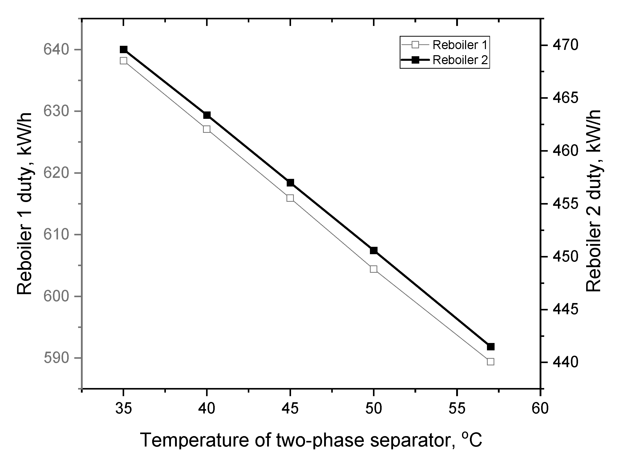
The simulation of the dehydration process using cyclopentane as an entrainer is challenging due to the strongly non-ideal behavior of the liquid phases [53]. First, the operating conditions, the number of trays in both columns, and the feed tray location in column C1, were established to achieve high-purity ethanol (99.94 wt.%) as the bottom product of column C1, while ensuring that the bottom product of column C2 is predominantly water with no more than 1000 ppm weight ethanol and no cyclopentane. Next, the effect of the temperature in the two-phase separator on the reboiler heat duties was investigated. As shown in Figure 3, increasing the temperature from 35 °C to 57.02 °C (the boiling point at 1.6 bar) reduces the reboiler duties. Consequently, the optimal separator temperature is 57.02 °C, corresponding to the lowest reboiler heat duties.
Table 4 presents the mass flow rates and mass concentrations of the components in the organic phase OP and aqueous phase AP of the two-phase separator and in both the bottoms (B2 and B3) products from column C2 and column C3.
The results presented in Table 4 demonstrate that cyclopentane is a favorable entrainer for ethanol dehydration via azeotropic distillation in a system comprising two columns and a two-liquid phase separator, under the operating conditions specified in Table 1. The objective of this study has been achieved: obtaining an ethanol with a purity of 99.94 wt.%. Additionally, the process yields two water-rich streams (B1 and B3), which can be combined and directed to a wastewater treatment facility [54].

3.3. Simulation Results and Discussion: Extractive Distillation Dehydration Process

As presented in Section 2.2 and Figure 2, the dehydration process based on extractive distillation with ethylene glycol (EG) has the extractive distillation column (EDC) as its key unit. After the operating parameters have been established (Table 2), the most critical design variable is the solvent flow rate, since it determines whether the required distillate (D2) purity of 99.94 wt.% ethanol can be achieved. It is also essential that the solvent be effectively regenerated in the SRC, allowing it to be recycled to the EDC with a maximum water content of 10 ppm by weight. Furthermore, the distillate of the SRC (D3) must be predominantly a water stream, with only trace ethanol (hundreds of ppm weight) and without EG, to be sent together with the B1 stream to a wastewater treatment facility. Our simulations considered all these requirements and identified the optimal configuration of the investigated process to achieve them. The results are presented in Table 5.
The results shown in Table 5 clearly demonstrate that the distillate D2 column contains dehydrated ethanol (99.94% by weight), while the distillate D3 is predominantly water with only 492 ppm of ethanol and no EG, as intended. The solvent is very effectively regenerated in the SRC, operated under the conditions summarized in Table 2, with the recycled EG stream containing only 10 ppm of water by weight. As in the azeotropic distillation process, the water-rich streams can be combined and sent to a treatment facility.

3.4. Results of Economic Evaluation and Discussion

In this section, the capital cost, utilities cost, and Total Annual Cost (TAC) for the two dehydration processes are compared. To calculate the TAC, the total annualized capital cost (TACC) must first be determined. The TACC (annualized capital cost) calculation includes the cost of all equipment: columns and heat exchangers. The correlations used to calculate individual equipment costs are presented in Table S15 of the Supplementary Materials. For columns, the relevant size parameters are diameter and height, while for heat exchangers, the relevant parameter is the heat transfer area. These relevant size parameters are obtained from simulations performed under the operating conditions of each equipment (Table 1 and Table 2), as well as for the separation performances reported in Table 3, Table 4 and Table 5. The values of the relevant parameters, summarized in Table 6, are then introduced into the above-mentioned cost correlations.
As mentioned in Section 2.3, the TACC calculation includes the cost of the entrainer (i.e., cyclopentane) or the extractive distillation solvent (i.e., ethylene glycol) only at the first start-up of each installation. During continuous operation, the entrainer or solvent is recycled. Of course, there are annual solvent or entrainer losses that must be replenished, but their cost is not quantified because it is considered insignificant. The purchase cost of each piece of equipment is updated using the Marshall and Swift Cost Index. TACC is depreciated over a three-year period. For the total annual energy cost (TAEC), steam consumption in the reboilers and cooling water usage for the condensers and coolers must be quantified. Based on simulations performed for each installation, the thermal loads of the heat exchange devices were obtained, expressed in GJ/h. The cost of the different types of saturated steam is specified in Table S15 in the Supplementary Materials, in units of USD/GJ. Therefore, by multiplying the thermal load (duty) by the cost of each type of utility, and by 8000 operating hours/year. The relevant values implied in the cost calculation of each process under investigation are presented in Table 6.
Based on the data in Table 6 and the cost calculation correlations presented in Table S15 from the Supplementary Material, the total annualized capital cost (TACC), total annual energy cost (TAEC), and total annual cost (TAC) were determined for each dehydration process under study. Table 7 presents the results of the economic evaluation.
Analyzing the results of the economic comparison, it is evident that the capital annualized cost (TACC) with the azeotropic distillation process is 36.5% higher than that with the extractive distillation process. This difference can be explained as follows: the two columns in the azeotropic distillation process are taller than those in the extractive distillation process. Moreover, the entrainer (cyclopentane) is required at a higher flow rate, and it is more expensive than the solvent (ethylene glycol). In addition, the condenser (Condenser C) shared by the columns C1 and C2 (Figure 1) has a larger area than the combined areas of Condenser 2 of the EDC and Condenser 3 of the SRC (Figure 2), resulting in a higher cost. The operating annual costs (TAEC) of the extractive distillation process are slightly higher than those of the azeotropic process, not because of higher steam consumption in the reboilers, but due to higher cost of steam: in extractive distillation process, medium-pressure steam is used in the Reboiler 2 and high-pressure steam in the Reboiler 3 (Figure 2), while in azeotropic process only low-pressure steam is used. The significant difference in investment costs is also reflected in the TAC, which in the azeotropic process is 25.6% higher than for the extractive distillation process in ethanol dehydration.
The azeotropic process using cyclopentane offers low-energy consumption and water streams free of entrainer, although VOC emissions must be controlled through full recovery loops. Cyclopentane is non-polar, low-biodegradable, and requires careful handling to prevent environmental release. The extractive process with ethylene glycol produces minimal VOC emissions. Regarding the water stream D3, the simulations considered the toxicity of ethylene glycol, and the extractive distillation process was designed to limit its presence to only 0.0002 kg/h (see Table 5), a level that is effectively non-contaminating for the water directed to the treatment plant [41,55]. Energy consumption is higher due to medium- and high-pressure steam, resulting in a larger indirect CO2 footprint. Overall, the two processes present a trade-off between solvent recovery, energy use, and wastewater treatment requirements [56].

4. Conclusions

This study performed a comprehensive simulation and techno-economic comparison of two bioethanol dehydration routes: azeotropic distillation using cyclopentane as a novel entrainer, and extractive distillation with ethylene glycol. Cyclopentane proved to be an effective entrainer, achieving ethanol purity of 99.94 wt.% and producing water streams essentially free of solvent, suitable for direct wastewater treatment. Comparable ethanol purity (99.94 wt.%) was obtained in the extractive configuration with ethylene glycol. The azeotropic process exhibited approximately 36.5% higher capital cost than the extractive system, primarily due to taller columns, larger heat-exchange areas, and higher cyclopentane purchase costs and flow rates. However, its operating costs were lower, since only low-pressure steam was required, whereas the extractive process demanded medium- and high-pressure steam. Consequently, the total annual cost (TAC) of the azeotropic configuration was about 25.6% higher than that of the extractive process. Despite this, the cyclopentane-based process remains technically viable for producing fuel-grade ethanol, and any residual entrainer in the ethanol stream would not impair fuel quality—unlike ethylene glycol, which is incompatible with gasoline blending. The current market price of cyclopentane limits its economic competitiveness; nevertheless, entrainer costs are highly region- and time-dependent. This work establishes a quantitative benchmark identifying the cost ranges under which cyclopentane could become a feasible alternative. In regions where cyclopentane is locally available or more affordable, the proposed design provides a reliable framework for evaluating its practical adoption. Even if the process proves economically unfavorable under present conditions, the results deliver valuable insight by delineating the realistic boundaries of this alternative and preventing inefficient industrial trials. Beyond ethanol dehydration, this study contributes to a broader understanding of entrainer selection criteria and cost sensitivity in azeotropic and extractive distillation systems. The findings may serve as a foundation for future research focusing on thermodynamic screening of potential entrainers, process intensification, and integrated energy-saving configurations.

Supplementary Materials

The following supporting information can be downloaded at: https://www.mdpi.com/article/10.3390/pr13113634/s1. Table S1. Influence of reflux ratio R on separation performance in PC and on heat exchangers’ duties, at: NT = 13, NFT = 7; Table S2. Influence of the NT on separation performance in PC and on heat exchangers’ duties, at: R = 2.0 and NFT = 7; Table S3. Influence of the NFT on separation performance in PC and on heat exchangers’ duties, at: R = 2.0 and NT = 17; Table S4. Influence of OP flow rate on separation in C1 and C2 columns and on heat exchangers’ duties, at: AP flow rate = 45 kmol/h (2097.98 kg/h), NT (C1) = 23, NT (C2) = 18, and NFT (C1) = 6; Table S5. Influence of AP flow rate on separation in C1 and C2 columns and on heat exchangers’ duties, at: OF flow rate = 60 kmol/h (4197.81 kg/h), NT (C1) = 23, NT (C2) = 18, and NFT (C1) = 6; Table S6. Influence of NT (C1) on separation in C1 and C2 columns and on heat exchangers’ duties, at: AP flow rate = 45 kmol/h (2097.98 kg/h), OP flow rate = 60 kmol/h (4197.81 kg/h), NT (C2) =18, and NFT (C1) = 6; Table S7. Influence of NFT (C1) on separation in C1 and C2 columns and on heat exchangers’ duties, at: AP flow rate = 45 kmol/h (2097.98 kg/h), OP flow rate = 60 kmol/h (4197.81 kg/h), NT (C1) = 23, NT (C2) = 18; Table S8. Influence of NT (C2) on separation in C1 and C2 columns and on heat exchangers’ duties, at: AP flow rate = 45 kmol/h (2097.98 kg/h), OP flow rate = 60 kmol/h (4197.81 kg/h), NT (C1) = 23, NFT = 6; Table S9. Influence of solvent to feed ratio S/F on separation performance in EDC and on heat exchangers’ duties, at: NT (EDC) = 18, NFT (EDC) = 14, NTF (S) = 5, and R = 1.0; Table S10. Influence of the NT (EDC) on separation performance in EDC and on heat exchangers’ duties, at: S/F = 1.7/1.0, R = 1.0, NFT (EDC) = 14 and NTF (S) = 5; Table S11. Influence of the NFT (EDC) on separation performance in EDC and on heat exchangers’ duties, at: S/F = 1.7/1.0, R = 1.0, NT (EDC) = 22 and NTF (S) = 5; Table S12. Influence of reflux ratio R on separation performance in EDC and on heat exchangers’ duties, at: S/F = 1.7/1.0, NT (EDC) = 22, NFT (EDC) = 14, and NTF (S) = 5. Table S13. Influence of the NT (SRC) on separation performance in SRC and on heat exchangers’ duties, at: R = 5.0/1.0 and NFT (SRC) = 7; Table S14. Influence of the reflux ratio R on separation performance in SRC and on heat exchangers’ duties, at: NT (SRC) = 18 and NFT (SRC) = 7; Table S15. Formulas and data utilized for the economic evaluation.

Author Contributions

Conceptualization, M.N.; methodology, M.N. and M.P.-N.; software, M.N. and M.P.-N.; validation, M.N.; formal analysis, M.P.-N.; writing—original draft preparation, M.N.; writing—review and editing, M.P.-N.; supervision, M.N. All authors have read and agreed to the published version of the manuscript.

Funding

This research received no external funding.

Data Availability Statement

The original contributions presented in this study are included in the article/Supplementary Material. Further inquiries can be directed to the corresponding author.

Conflicts of Interest

The authors declare no conflict of interest.

Abbreviations

The following abbreviations are used in this manuscript:
EGethylene glycol
EDextractive distillation
LMTDslog-mean temperature differences
NRTLNon-Random Two Liquid
UNIFACUniversal Functional-group Activity Coefficients
TACCtotal annualized capital costs ($/year)
TAECtotal annual energy costs ($/year)
TACtotal annual cost ($/year)
Symbols
PCpreconcentration column
C1ethanol dehydration column
C2water separation column
EDCextractive distillation column
SRCextractive-solvent recovery column
B nbottom product for column n (kg/h)
D ndistillate product for column n (kg/h)
Reboiler nreboiler of column n
Condenser ncondenser of column n
Condenser C condenser of C1 and C2 column
Coolercooler

References

  1. Lee, Y.-Y.; Srinivaas, M.; Li, I.-C.; Keharika, K.; Pothu, R.; Boddula, R.; Al-Qahtani, N.; Huang, B.-W.; Chang-Chien, G.-P. Enchanging Sustainable Energy Through Cutting-Edge Waste Biorefinery Technologies. Reactions 2024, 5, 1101–1147. [Google Scholar] [CrossRef]
  2. Areeya, S.; Pannakkal, E.J.; Kunmanee, P.; Tawai, A.; Amornraksa, S.; Sriarivanun, M. A Review of Sugarcane Biorefinery: From Waste to Value-Added Products. Appl. Sci. Eng. Prog. 2024, 17, 74022. [Google Scholar] [CrossRef]
  3. Patel, R.; Rajaraman, T.S.; Rana, H.P.; Ambegaonkar, J.N.; Patel, S. A review on techno-economic analysis of lignocellulosic biorefinery producing biofuels and high-value products. Results Chem. 2025, 13, 102052. [Google Scholar] [CrossRef]
  4. Rola, K.; Gruber, S.; Goričanec, D.; Urbancl, D. Waste Lignocellulosic Biomass as a Source for Bioethanol Production. Sustain. Chem. 2024, 5, 1–12. [Google Scholar] [CrossRef]
  5. Kumar, V.; Kumar, P.; Maity, K.S.; Agrawal, D.; Narisetty, V.; Jacob, S.; Kumar, G.; Bhatia, S.K.; Kumar, D.; Vivekanand, V. Recent advances in bio-based production of top platform chemical, succinic acid: An alternative to conventional chemistry. Biotechnol. Biofuels Bioprod. 2024, 17, 72. [Google Scholar] [CrossRef] [PubMed]
  6. Ioannidou, S.M.; Pateraki, C.; Ladakis, D.; Papapostolou, H.; Tsakona, M.; Vlysidis, A.; Kookos, I.K.; Koutinas, A. Sustainable production of bio-based chemicals and polymers via integrated biomass refining and bioprocessing in a circular bio-economy context. Bioresour. Tech. 2020, 307, 123093. [Google Scholar] [CrossRef]
  7. Zhao, X.; Wang, Y.; Chen, X.; Yu, X.; Li, W.; Zhang, S.; Meng, X.; Zhao, Z.-M.; Dong, T.; Anderson, A.; et al. Sustainable bioplastics derived from renewable natural resources for food packaging. Matter 2023, 6, 97–127. [Google Scholar] [CrossRef]
  8. Broda, M.; Yelle, J.D.; Serwańska, K. Bioethanol Production from Lignocellulosic Biomass—Challenges and Solutions. Molecules 2022, 27, 8717. [Google Scholar] [CrossRef]
  9. Raj, T.; Chandrasekhar, K.; Kumar, A.N.; Banu, J.R.; Yoon, J.-J.; Bhatia, S.K.; Yang, Y.-H.; Varjani, S.; Kim, S.-H. Recent advances in commercial biorefineries for lignocellulosic ethanol production: Current status, challenges and future perspectives. Bioresour. Technol. 2022, 344, 126292. [Google Scholar] [CrossRef]
  10. Kiss, A.A. Advanced Distillation Technologies: Design, Control and Applications; John Wiley & Sons Ltd.: Chichester, UK, 2013. [Google Scholar]
  11. Gil, I.D.; Gómez, J.M.; Rodríguez, G. Control of an extractive distillation process to dehydrate ethanol using glycerol as entrainer. Comput. Chem. Eng. 2012, 39, 129–142. [Google Scholar] [CrossRef]
  12. Sánchez-Correa, C.A.; Arturo-Calvache, J.E.; Gil-Chaves, I.D.; Rodríguez-Niño, G. Multiplicities in ethanol dehydration by extractive distillation processes with ethyleneglycol. Chem. Eng. Process. Process Intensif. 2022, 174, 108886. [Google Scholar] [CrossRef]
  13. Plesu Popescu, A.E.; Pellin, J.L.; Bonet, J.; Llorens, J. Bioethanol dehydration and mixing by heterogeneous azeotropic distillation. J. Clean. Prod. 2021, 320, 128810. [Google Scholar] [CrossRef]
  14. Mittal, N.; Bai, P.; Siepmann, J.I.; Daoutidis, P.; Tsapatsis, M. Bioethanol enrichment using zeolite membranes: Molecular modeling, conceptual process design and techno-economic analysis. J. Membr. Sci. 2017, 540, 464–476. [Google Scholar] [CrossRef]
  15. Karimi, S.; Yaraki, M.T.; Karri, R.R. A comprehensive review of the adsorption mechanisms and factors influencing the adsorption process from the perspective of bioethanol dehydration. Renew. Sustain. Energy Rev. 2019, 107, 535–553. [Google Scholar] [CrossRef]
  16. de Jesús Hernández-Hernández, E.; Cabrera-Ruiz, J.; Hernández-Escoto, H.; Gutiérrez-Antonio, C.; Hernández, S. Simulation study of the production of high purity ethanol using extractive distillation: Revisiting the use of inorganic salts. Chem. Eng. Process. Process Intensif. 2022, 170, 108670. [Google Scholar] [CrossRef]
  17. Kiss, A.A.; Suszwalak, D.J.P.C. Enhanced bioethanol dehydration by extractive and azeotropic distillation in dividing-wall columns. Sep. Purif. Technol. 2012, 86, 70–78. [Google Scholar] [CrossRef]
  18. Hernández-Escoto, H.; Zavala-Guzmán, A.M.; Maya-Yescas, R.; Zamudio-Lara, J.M.; Hernández, S. Operability assessment and systematic PI control of a class of Extractive Dividing Wall Distillation Columns: Case of ethanol dehydration. Chem. Eng. Res. Des. 2022, 187, 84–92. [Google Scholar] [CrossRef]
  19. Singh, A.; da Cunha, S.; Rangaiah, G.P. Heat-pump assisted distillation versus double-effect distillation for bioethanol recovery followed by pressure swing adsorption for bioethanol dehydration. Sep. Purif. Technol. 2019, 210, 574–586. [Google Scholar] [CrossRef]
  20. Beluhan, S.; Mihajlovski, K.; Šantek, B.; Ivančić Šantek, M. The Production of Bioethanol from Lignocellulosic Biomass: Pretreatment Methods, Fermentation, and Downstream Processing. Energies 2023, 16, 7003. [Google Scholar] [CrossRef]
  21. Zhai, J.; Sun, X.; Huang, S.; Xie, H.; Chen, X. Economic, thermodynamic, environmental, and inherent safety investigation of heat pump-assisted extractive dividing wall column for separating binary azeotrope. Process Saf. Environ. Prot. 2023, 173, 202–214. [Google Scholar] [CrossRef]
  22. Zhao, G.; Gao, H.; Qu, Z.; Fan, H.; Meng, H. Anhydrous interfacial polymerization of sub-1 Å sieving polyamide membrane. Nat. Commun. 2023, 14, 7624. [Google Scholar] [CrossRef] [PubMed]
  23. Wu, Q.; Wang, Z.; Xu, W.; Xin, L.; Hu, R.; Zhu, Z.; Wang, Y.; Cui, P. Innovative extractive distillation process combining preconcentration and solvent recovery functions for efficiently separating diisopropyl ether/isopropanol/water. Sep. Purif. Technol. 2025, 360, 131021. [Google Scholar] [CrossRef]
  24. Wang, Z.; Xin, L.; Wang, Y.; Wu, Q.; Xu, W.; Zhu, Z.; Wang, Y.; Cui, P. Optimization and dynamic control of green energy-saving process for azeotropes separation by mixed solvent extractive distillation. Renew. Sustain. Energy Rev. 2025, 218, 115813. [Google Scholar] [CrossRef]
  25. Duan, C.; Li, C. Energy-saving improvement of heat integration for separating dilute azeotropic components in extractive distillation: Part II—Process integration. Sep. Purif. Technol. 2025, 360, 131009. [Google Scholar] [CrossRef]
  26. Nicolae, M.; Neagu, M.; Cursaru, D.-L. Energy-Saving Extractive Distillation Process for Isopropanol Dehydration with Propylene Glycol as Novel Extractive Solvent. Appl. Sci. 2024, 14, 9420. [Google Scholar] [CrossRef]
  27. Luyben, W.L. Control of a multiunit heterogeneous azeotropic distillation process. AIChE J. 2006, 52, 623–637. [Google Scholar] [CrossRef]
  28. Gutiérrez-Antonio, C.; Jiménez-Gutiérrez, A. Design of side-stream azeotropic distillation columns. Chem. Eng. Res. Des. 2007, 85, 1384–1389. [Google Scholar] [CrossRef]
  29. Gomis, V.; Pedraza, R.; Saquete, M.D.; Font, A.; Garcia-Cano, J. Ethanol dehydration via azeotropic distillation with gasoline fractions as entrainers: A pilot-scale study of the manufacture of an ethanol–hydrocarbon fuel blend. Fuel 2015, 139, 568–574. [Google Scholar] [CrossRef]
  30. Cane, C. Dehydration of Alcohols, Preferably Ethanol, Using a Cyclohexane Entrainer. EP0001681A1, 2 May 1979. [Google Scholar]
  31. Baiel, J.J.; Tsonopoulos, C. High-Pressure Azeotropic Distillation for the Manufacture of Anhydrous Alcohols. U.S. Patent 4161429A, 17 July 1979. [Google Scholar]
  32. Batista, F.R.M.; Follegatti-Romero, L.A.; Bessa, L.C.B.A.; Meirelles, A.J.A. Computational simulation applied to the investigation of industrial plants for bioethanol distillation. Comput. Chem. Eng. 2012, 46, 1–16. [Google Scholar] [CrossRef]
  33. de Figueiredo, M.F.; Brito, K.D.; Ramos, W.B.; Sales Vasconcelos, L.G.; Brito, R.P. Effect of Solvent Content on the Separation and the Energy Consumption of Extractive Distillation Columns. Chem. Eng. Commun. 2015, 202, 1191–1199. [Google Scholar] [CrossRef]
  34. Jaime, J.A.; Rodríguez, G.; Gil, I.D. Control of an Optimal Extractive Distillation Process with Mixed-Solvents as Separating Agent. Ind. Eng. Chem. Res. 2018, 57, 9615–9962. [Google Scholar] [CrossRef]
  35. Miranda, N.T.; Maciel Filho, R.; Wolf Maciel, M.R. Comparison of Complete Extractive and Azeotropic Distillation Processes for Anhydrous Ethanol Production Using Aspen Plus™ Simulator. Chem. Eng. Trans. 2020, 80, 43–48. [Google Scholar] [CrossRef]
  36. Fattahi, T.; Salehi, E.; Hosseini, Z. Intensification of Azeotropic Distillation for Ethanol Dehydration using Data-based Optimization, Steady-state Simulation and Sensitivity Analysis. Iran. J. Chem. Eng. IJCE 2023, 20, 15–32. [Google Scholar] [CrossRef]
  37. Nicolae, M.; Fendu, E.M. Experimental and Regression VLE Data for Ethanol + DPG Binary System: Ethanol Anhydrization Process Simulation Using DPG as Extractive Agent. Period. Polytech. Chem. Eng. 2024, 68, 454–469. [Google Scholar] [CrossRef]
  38. ANP 36; Establishing the Specification for Fuel Ethanol (Anhydrous and Hydrated) for Automotive Use Blended with Gasoline. National Petroleum, Natural Gas and Biofuels Agency: Brasília, Brazil, 2005.
  39. EN 15376; Automotive Fuels—Ethanol as a Blending Component for Petrol—Requirements and Test Methods. European Committee for Standardization (CEN)—CEN-CENELEC Management Centre: Brussels, Belgium, 2014. Available online: https://www.intertekinform.com/preview/98703763611.pdf (accessed on 20 September 2025).
  40. ASTM D 4806-03; Standard Specification for Denatured Fuel Ethanol for Blending with Gasolines for Use as Automotive Spark-Ignition Engine Fuel. ASTM International: West Conshohocken, PA, USA, 2003. Available online: https://kelid1.ir/FilesUp/ASTM_STANDARS_971222/D4806.PDF?utm (accessed on 20 September 2025).
  41. Council Directive 91/271/EEC of 21 May 1991 Concerning Urban Waste-Water Treatment. Available online: https://eur-lex.europa.eu/eli/dir/1991/271/oj/eng (accessed on 6 September 2025).
  42. Process Simulation of Aveva Software, version AVEVA PRO/II; AVEVA: Cambridge, UK, 2024.
  43. Lide, D.R.; Kehiaian, H.V. CRC Handbook of Thermophysical and Thermochemical Data; CRC Press: Boca Raton, FL, USA, 1994. [Google Scholar]
  44. Horsley, L.H. Azeotropic Data, III; American Chemical Society: Washington, DC, USA, 1973; Volume 17, p. 134. [Google Scholar]
  45. Howard, H.P.; Michalenko, M.E.; Meylan, M.W.; Basu, K.D.; Beauman, A.J.; Sage, W.G.; Jarvis, F.W.; Gray, D.A. Chapter: Cyclopentane. In Handbook of Environmental Fate and Exposure Data for Organic Chemicals, 1st ed.; Howard, P., Ed.; Imprint CRC Press: Boca Raton, FL, USA, 1993; Volume IV. [Google Scholar]
  46. Wu, J.; Gao, L.-G.; Ren, W.; Truhlar, D.G. Anharmonic kinetics of the cyclopentane reaction with hydroxyl radical. Chem. Sci. 2020, 11, 2511. [Google Scholar] [CrossRef]
  47. Jindamanee, K.; Keawboonchu, J.; Pinthong, N.; Meeyai, A.; Inchai, P.; Thepanondh, S. Environmental impacts and emission profiles of volatile organic compounds from petroleum refineries. Sci. Rep. 2025, 15, 15509. [Google Scholar] [CrossRef]
  48. Stokes, R.; Moosemiller, M. Distillation Improvement Opportunities, Part 6: Safety Implications from New Technologies. Chem. Eng. 2023, 989. Available online: https://www.thechemicalengineer.com/features/distillation-improvement-opportunities-part-6-safety-implications-from-new-technologies (accessed on 31 October 2025).
  49. Valentini, F.; Vaccaro, L. Azeotropes as Powerful Tool for Waste Minimization in Industry and Chemical Processes. Molecules 2020, 25, 5264. [Google Scholar] [CrossRef] [PubMed]
  50. Luyben, W.L. Plantwide control of an isopropyl alcohol dehydration process. AIChE J. 2006, 52, 2290–2296. [Google Scholar] [CrossRef]
  51. Sinnott, R.K. Chemical Engineering Design, 4th ed.; Coulson & Richardson’s Chemical Engineering Series; Elsevier Butterworth-Heinemann: Oxford, UK, 2005; Volume 6. [Google Scholar]
  52. Cui, Y.; Zhang, Z.; Shi, X.; Guang, C.; Gao, J. Triple-column side-stream extractive distillation optimization via simulated annealing for the benzene/isopropanol/water separation. Sep. Purif. Technol. 2020, 236, 116303. [Google Scholar] [CrossRef]
  53. Prausnitz, J.; Lichtenthaler, R.; de Azevedo, E.G. Molecular Thermodynamics of Fluid-Phase Equilibria, 3rd ed.; Prentice Hall PTR: Upper Saddle River, NJ, USA, 1999. [Google Scholar]
  54. Sommer, S.; Melin, T. Design and Optimization of Hybrid Separation Processes for the Dehydration of 2-Propanol and Other Organics. Ind. Eng. Chem. Res. 2004, 43, 5248–5259. [Google Scholar] [CrossRef]
  55. Staples, C.A.; Williams, J.B.; Craig, G.R.; Roberts, K.M. Fate, effects and potential environmental risks of ethylene glycol: A review. Chemosphere 2001, 43, 377–383. [Google Scholar] [CrossRef] [PubMed]
  56. Avilés-Martínez, A.; Medina-Herrera, N.; Jiménez-Gutiérrez, A.; Serna-González, M.; Castro-Montoya, A.J. Risk Analysis Applied to Bioethanol Dehydration Processes: Azeotropic Distillation versus Extractive Distillation. Comput. Aided Chem. Eng. 2015, 37, 1835–1840. [Google Scholar] [CrossRef]
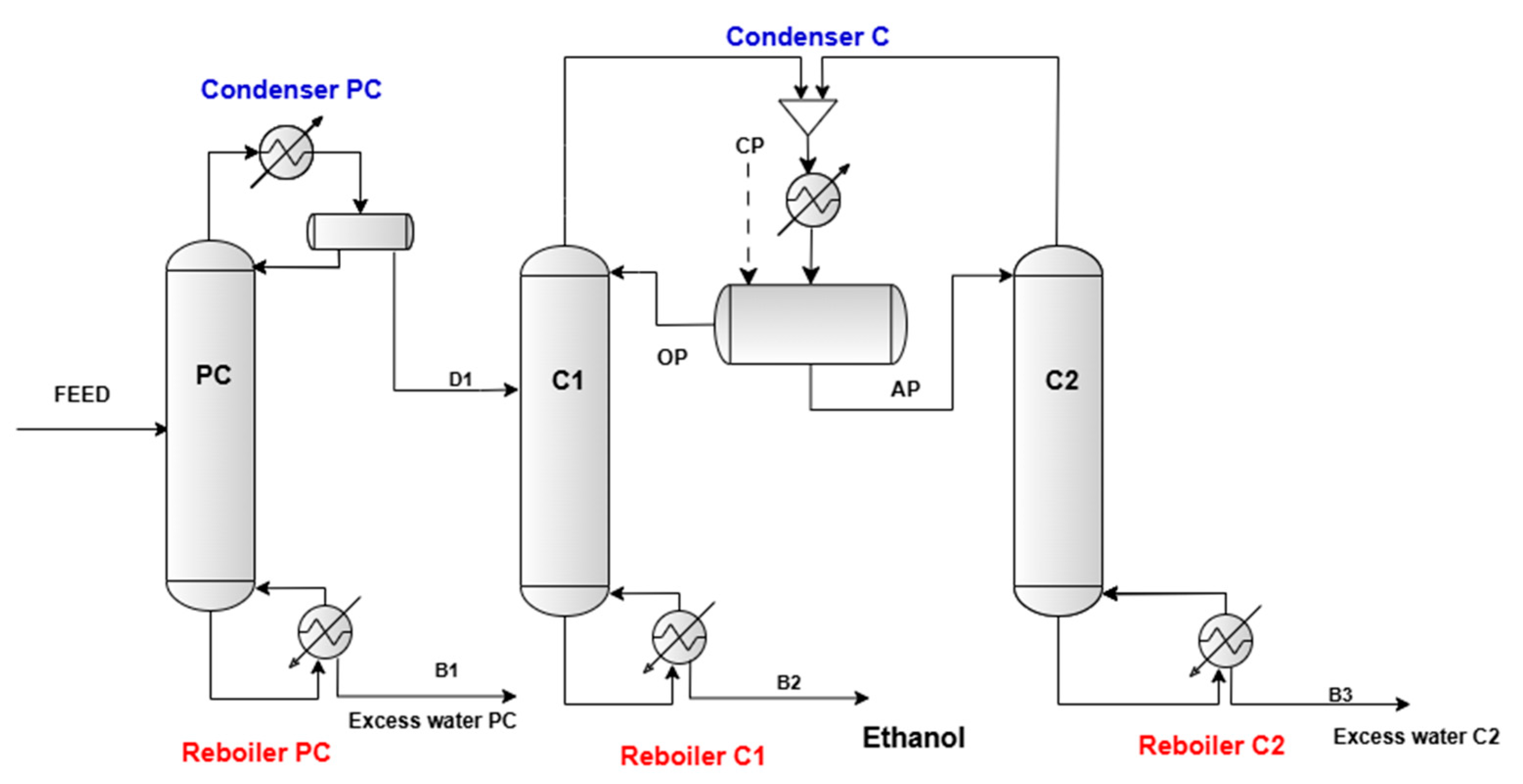
Figure 1. The proposed flowsheet for ethanol dehydration by azeotropic distillation with CP.
Processes 13 03634 g001
Figure 2. The proposed flowsheet for ethanol dehydration by extractive distillation with EG.
Processes 13 03634 g002
Figure 3. Reboiler heat duties over temperature in the two-phase separator.
Processes 13 03634 g003
Table 1. The operating conditions of columns PC, C1, and C2.
ParametersColumn PCColumn C1Column C2
Number of trays 17 124 119 1
Feed tray number1061
Top pressure, bar1.61.61.6
Bottom pressure, bar1.771.841.79
Top temperature, °C86.5557.4781.16
Bottom temperature, °C116.3394.25116.67
Reflux ratio, molar 22.0--
1 Numbered from top to bottom. 2 Reflux ratio is the ratio between the molar flow rate of liquid returned to the top tray (or tray 1) and the molar flow rate of the distillate product [39].
Table 2. The operating conditions of columns PC, EDC, and SRC.
ParametersColumn PCColumn EDCColumn SRC
Number of trays 17 122 116 1
Feed tray number10187
Feed solvent tray number-5-
Top pressure, bar1.61.31.15
Bottom pressure, bar1.771.521.22
Top temperature, °C86.5580.4097.15
Bottom temperature, °C116.33184.21203.87
Reflux ratio, molar2.02.05.0
1 Numbered from top to bottom.
Table 3. The mass flow rates and mass concentrations of components in distillate (D1) and bottom (B1) flows.
ComponentsDistillate Flow
(D1), kg/h
Mass Concentration in D1, wt.%Bottom Flow
(B1), kg/h
Mass Concentration in B1, wt.%
Ethanol991.096290.418.90380.100
Water105.15849.598894.841699.90
Total1096.2546100.008903.7454100.00
Table 4. The mass flow rates and mass concentrations of components in the organic phase OP and aqueous phase AP of the two-phase separator, and in the bottom (B2) and bottom (B3) flows.
ComponentsOrganic Phase (OP) Flow, kg/hConcentration in OP, wt.%Aqueous Phase (AP) Flow, kg/hConcentration in AP, wt.%Bottom Flow (B2), kg/hConcentration in B2, wt.%Bottom Flow (B3), kg/hConcentration in B3, wt.%
Ethanol12.010.286902.3943.01664.7399.940.05690.100
Water1.370.0326203.559.700.0020.000356.832299.90
Cyclopentane4184.4399.68992.0447.290.4180.06300.000.00
Total4197.81100.002097.98100.00665.15100.0056.8890100.00
Table 5. The mass flow rates and mass concentrations of components in distillates (D2) and (D3) flows and in bottom (B2) and (B3) flows.
ComponentsDistillate Flow (D2), kg/hConcentration in D2, wt.%Distillate Flow (D3), kg/hConcentration in D3, wt.%Bottom Flow (B2), kg/hConcentration in B2, wt.%Bottom Flow (B3), kg/hConcentration in B3, wt.%
Ethanol991.0299.940.05140.04920.05140.002630.00.00
Water0.5950.06104.5499.95104.565.370.01840.001
Ethylene glycol0.0090.00.00020.01844.2894.631844.28100.00
Total991.62100.00104.59100.001948.89100.001844.30100.00
Table 6. Detailed design parameters of the azeotropic and extractive distillation processes.
Parameter, u.mPCAzeotropic Distillation ProcessExtractive Distillation Process
C1C2EDCSRC
Diameter, m0.7620.7620.610.610.381 1/0.61 2
Height, m31.669.5457.036.8544.1
Reboiler duty, kW/h1721.0589.4441.5609.6177.7
Reboiler area, m270.515.9618.0526.326.22
Steam consumption, kg/h2971.01017.0762.01120.0377.0
Condenser duty, kW/h886.8916.4463.7131.8
Condenser area, m222.154.4313.22.58
Water consumption, kg/h42,362.30643,776.02222,152.8016296.986
Cooler duty, kW/h---195.4
Cooler area, m2---2.6
Water consumption, kg/h---9334.344
1 Diameter of the upper zone. 2 Diameter of the lower zone.
Table 7. Results of economic evaluation for ethanol dehydration by azeotropic distillation process compared to the extractive distillation process.
Azeotropic Distillation ProcessExtractive Distillation Process
Capital cost (TACC) (a), $4,615,9952,929,493
Utilities cost (TAEC), $/year634,986640,647
TAC (a), $/year2,173,6511,617,144
(a) Includes the cost of purchasing the solvent (at the start-up of the plant).
Disclaimer/Publisher’s Note: The statements, opinions and data contained in all publications are solely those of the individual author(s) and contributor(s) and not of MDPI and/or the editor(s). MDPI and/or the editor(s) disclaim responsibility for any injury to people or property resulting from any ideas, methods, instructions or products referred to in the content.