Subsurface MIMO: A Beamforming Design in Internet of Underground Things for Digital Agriculture Applications †


Department of Computer and Information Technology, Purdue University, West Lafayette, IN 47907, USA
†
This paper is an extended version of our paper published in International Conference on Internet of Things (ICIOT 2019), San Diego, CA, USA, 25–30 June 2019.
J. Sens. Actuator Netw. 2019, 8(3), 41; https://doi.org/10.3390/jsan8030041
Submission received: 13 July 2019
/
Revised: 1 August 2019
/
Accepted: 7 August 2019
/
Published: 10 August 2019
Abstract
:In underground (UG) multiple-input and multiple-output (MIMO), transmit beamforming is used to focus energy in the desired direction. There are three different paths in the underground soil medium through which the waves propagate to reach the receiver. When the UG receiver receives a desired data stream only from the desired path, then the UG MIMO channel becomes a three-path (lateral, direct, and reflected) interference channel. Accordingly, the capacity region of the UG MIMO three-path interference channel, and the degrees of freedom (multiplexing gain of this MIMO channel) requires careful modeling. Therefore, expressions are required for the degrees of freedom of the UG MIMO interference channel. The underground receiver needs to perfectly cancel the interference from the three different components of the EM waves propagating in the soil medium. This concept is based upon reducing the interference of the undesired components to a minimum level at the UG receiver using the receive beamforming. In this paper, underground environment-aware MIMO using transmit and receive beamforming has been developed. The optimal transmit and receive beamforming, combining vectors under minimal intercomponent interference constraints, are derived. It is shown that UG MIMO performs best when all three components of the wireless UG channel are leveraged for beamforming. The environment-aware UG MIMO technique leads to three-fold performance improvements and paves the way for design and development of next-generation sensor-guided irrigation systems in the field of digital agriculture. Based on the analysis of underground radio-wave propagation in subsurface radio channels, a phased-array antenna design is presented that uses water content information and beam-steering mechanisms to improve efficiency and communication range of wireless underground communications. It is shown that the subsurface beamforming using phased-array antennas improves wireless underground communications by using the array element optimization and soil–air interface refraction adjustment schemes. This design is useful for subsurface communication system where sophisticated sensors and software systems are used as data collection tools that measure, record, and manage spatial and temporal data in the field of digital agriculture.
1. Introduction
The purpose of digital agriculture is to tailor agricultural inputs and processes to localized environments in the farm to apply correct practices in the field in a timely and correct manner. It leads to the development of smart and digital sensing, communications, and real-time decision-making systems to sense, analyze, detect, and manage the soil and farm-specific spatial and temporal patterns in the field for sustainability, profitability, and to protect the environment.
The Internet of Underground Things (IOUT) have many applications in precision agriculture [1,2,3,4,5,6,7,8,9,10,11,12]. Border monitoring is another important application area of IOUT, where these networks are being used to enforce borders and stop infiltration [13,14]. Monitoring applications of IOUT include landslide monitoring and pipeline monitoring [5,15,16]. IOUT provides seamless access to information collected from agricultural fields through the Internet. IOUT includes in situ soil-sensing capabilities (e.g., soil moisture, temperature, salinity), and provides the ability to communicate through plants, soil and real-time information about the environment (e.g., wind, rain, solar). When interconnected with existing machinery on the field (seeders, irrigation systems, combines), IOUT enables complete autonomy in the field, and paves the way for more efficient food production solutions. At agricultural farm level, IOUT is being used to provide valuable information to farmers.
By using software-defined control of individual antenna elements, steering solutions for communications with static and mobile aboveground devices in digital agriculture can be implemented [17,18]. This kind of implementation of underground (UG) beamforming is challenging for many reasons. The major challenge is the phase shift between antenna elements. To get a desired beam pattern, the phase shifts between antenna elements need to be equal in the desired direction. This requires calibration of phase shifters and dynamic on-the-fly phase correction to achieve the desired beam. To address these challenges, digital beamforming using phased-array antennas based on soil moisture conditions to form dynamic beam patterns can be employed. We have investigated three different array designs. First design consists of two separate linear arrays, each with its own phase shifter with pre-defined parameters for communication with underground and aboveground arrays. Furthermore, beams are stitched such that several beam patterns are determined and designed based on the analyses of underground and aboveground devices and stored in a configuration database for on-demand use. The second design is based on two arrays stacked at different UG depths with phase shifting done in the software. This approach is based on processing in the software-defined radio to adapt to wavelength changes due to soil moisture conditions. The advantage of using this approach is that dynamic changes in the wavelength and phase variations due to UG channel dynamism can be compensated for without changing physical array arrangements. Moreover, less energy is required in comparison to traditional mechanical phase shifters. In the third design, the multi-dimensional arrays, structured in rectangular, planar, and circular arrangements to have simultaneous beams in multiple planes, are used.
UG transmit beamforming using phased-array antennas at the transmitter [18] has been used in the UG communications to maximize the lateral wave [19] by transmitting energy at a particular angle. By using this approach, the energy waste by sending signals in isotropic direction is reduced by forming the narrow-width beam and steering it accordingly. In underground wireless communications, the aim is to enhance the received signal strength and reduce the interference at the receiver. In over-the-air (OTA) wireless communications, a strong signal strength is attained by transmitting the signal from multiple antennas at different amplitudes and phases. Through this approach, the received signal components add coherently at the receiver. However, in underground communication, due to different wave propagation speed in different communication mediums (e.g., soil and air), coherent combining at the receiver in a constructive manner cannot be achieved. Therefore, an environment-aware UG multiple-input and multiple-output (MIMO) design is required.
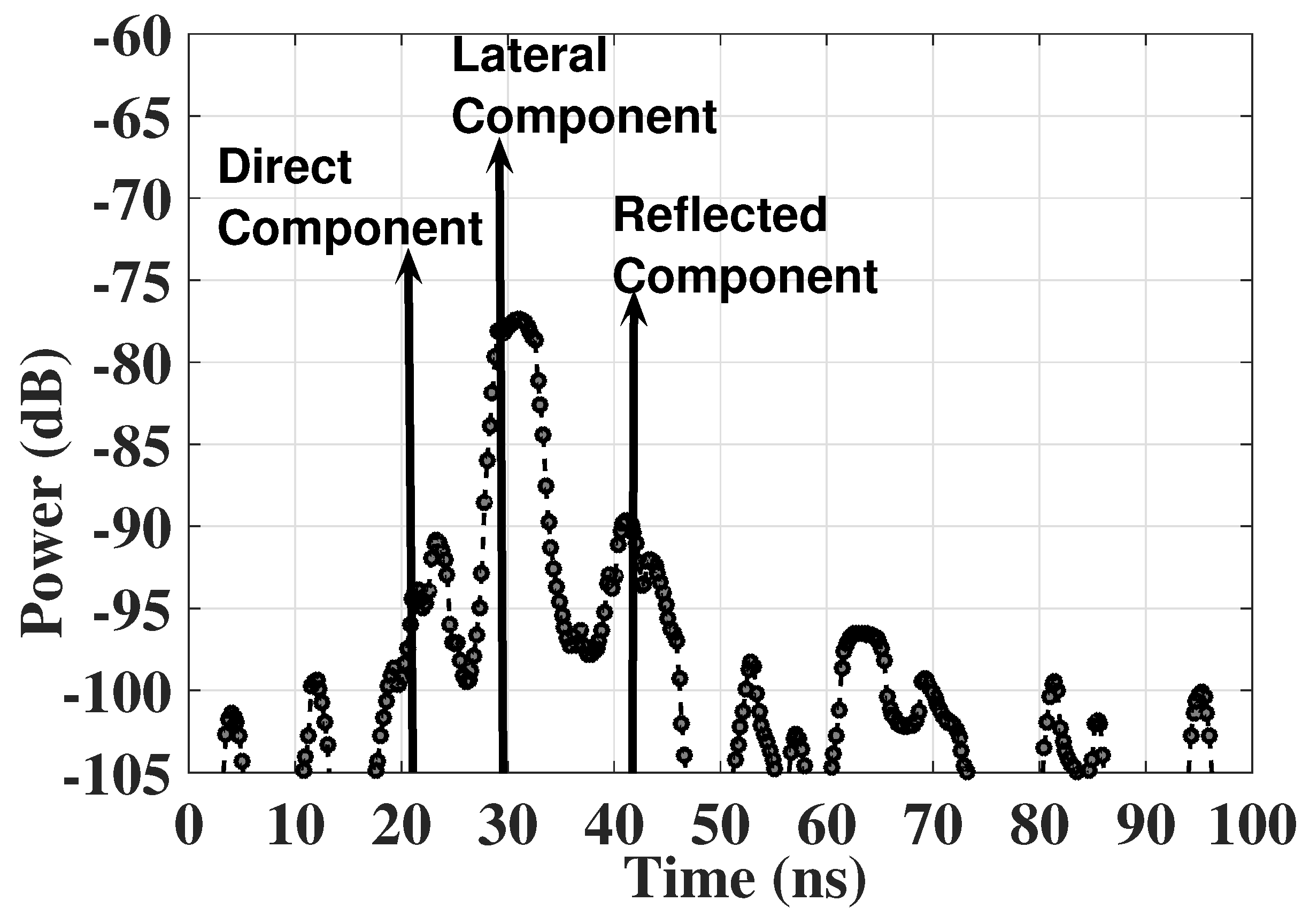
The line-of-sight (LoS) component between the UG transmitter and receiver has limitations because of the higher attenuation in the soil medium. An example power delay profile (PDP) of wireless UG channel is shown in Figure 1. Moreover, the direct path has shorter range and cannot be used to reach longer distances in the underground medium. Therefore, combined transmit and receive beamforming needs to be developed using non-LoS components (e.g., lateral and reflected). Since multipath underground channels are well-known [19] and have been studied and empirically validated, UG MIMO can be developed for high-data-rate and long-range communications. In this work, techniques have been developed to maximize the signal strength and minimize the interference at the receiver. Moreover, UG MIMO beamforming expressions have been developed to maximize the capacity of underground communications.
2. Related Work
An empirical analysis using off-the-shelf sensor motes to characterize the path loss in the UG channel was conducted in [19], and accordingly, path-loss models for underground-to-underground (UG2UG) and underground-to-aboveground (UG2AG) channels have been developed in [9].
Moreover, digital agriculture solutions including enabling technologies for subsurface antenna design [8], underground cognitive radio [20], and soil moisture sensing using subsurface radio-wave propagation have been developed for IOUT [11,12]. Accordingly, we devised a subsurface planar antenna [8], which combats adverse effects of time-variant subsurface radio channel characteristics and extends communication ranges of underground radios. This allows for development of architectures for connected soil moisture-sensing networks and automated irrigation solutions [11,12]. Moreover, it is shown that software-defined operation in underground communications can extend the capacity of the UG channel. The development of IoT-based smart security and monitoring devices for agriculture was investigated in [21]. A survey on advances in magnetic induction-based wireless underground sensor networks was presented in [22]. A secure smart agriculture monitoring technique through isolation was developed in [23]. The IoT vision, key features, applications, and open issues were discussed in [24]. IoT in agriculture, its recent advances, and future challenges were outlined in [25].
Beamforming antennas [26] are being used in wireless networks to reduce interference and improve capacity. Beamforming has been addressed in [27,28,29,30,31,32,33,34,35] for OTA wireless channels and in [36] for MI power transfer, but no existing work has considered underground beamforming. In UG communications, lateral component [37] has the potential, via beamforming techniques, to reach farther UG distances, which otherwise are limited (10 to 15 ) because of higher attenuation in soil [19].
3. Contributions of This Work
This is the first work to design a fully UG MIMO for UG communications. Transmit and receive beamforming techniques are considered, which communicate through the soil by using the UG channel medium. Based on the receiver position, EM waves either travel completely through the soil for UG communications or some part of it goes through the air for aboveground (AG) communications.
We leverage a UG channel impulse response model for the UG beamforming perspective and identify the major EM wave components. Challenges in UG beamforming are highlighted, and use of UG MIMO is motivated. We present the effects of different soil properties on beamforming vectors of the transmitter and receiver. This proposed mechanism estimates the best beam-steering angle based on the soil moisture sensing.
We have considered an UG MIMO transceiver system where both transmitter and receiver the beamforming capability. Additionally, this approach removes the intercomponent interference and enhances the received signal strength. Underground environment-aware MIMO using transmit and receive beamforming is vital for increased spectral efficiency, enhanced communication range, and energy efficiency in next-generation wireless underground networks, which are expected to include underground antenna arrays [18]. The UG MIMO approach has potential applications in many practical scenarios such as precision agriculture, ground-penetrating radars (GPR), hazardous object search, locating IEDs, transmission structures under runways for aircraft communications, antennas for geographic research, communications from marshes, geology, and wireless underground sensor networks (WUSNs).
4. The UG MIMO System Models
Underground nodes communicate with other underground nodes (UG2UG link) and aboveground nodes (UG2AG link). A communications schematic for UG MIMO communications is shown in Figure 2. These aboveground nodes are fixed sinks and mobile nodes are mounted on movable infrastructures such as center pivot. In aboveground communications, waves propagating to receiver nodes are refracted from the soil–air interface, whereas in UG communications, lateral waves need to be used. Desired beam patterns for both scenarios are shown in Figure 2. In Figure 2a, refractions and reflections of EM waves from the soil–air interface affect the beam patterns propagating to the aboveground node.
In UG MIMO, transmit beamforming [18] is used to focus energy in the desired direction. There are three different paths [19] in the underground soil medium through which the waves propagates to reach the receiver. When the UG receiver receives a desired data stream only from the desired path, then the UG MIMO channel becomes a three-path (lateral, direct, and reflected) interference channel. Accordingly, the capacity region of the UG MIMO three-path interference channel and degrees of freedom (multiplexing gain of this MIMO channel) requires careful modeling. Therefore, expressions are required to derive the degrees of freedom of the UG MIMO interference channel.
The underground receiver needs to perfectly cancel the interference from the three different components of the EM waves propagating in the soil medium. In UG transmit beamforming, limited numbers of antennas can only achieve low spatial directivity, which leads to the presence of signals in undesired directions causing interference at the receiver. This UG MIMO concept is based upon reducing the interference of the undesired components to a minimum at the UG receiver using the receive beamforming. In this paper, underground environment-aware MIMO using transmit and receive beamforming has been developed. The optimal transmit and receive beamforming combining vectors under minimal intercomponent interference constraints are derived. Accordingly, UG MIMO techniques are designed and investigated in the underground soil medium. Next we present the system model.
We consider a UG MIMO transceiver system where both transmitter and receiver has beamforming capability. We also consider that the transmitter node is equipped with two or more transmit antennas and has beam-steering capacity. The receiver node is also equipped with multiple antennas and can receive all three components propagating through the underground medium. In this paper, we also assume that the UG MIMO receiver has path selection and switching capability through a selection mechanism, which is based on the strength of the received paths at the receiver. Throughout the development of this approach, we also assume equal power allocation at the UG MIMO transmitter. To analyze the achievable capacity using environment-aware MIMO using transmit and receive beamforming, we also assume a total power constraint.
Next, we present a zero-forcing (ZF) UG MIMO transceiver technique. This approach does not require the availability of the channel state at the receiver in contrast to the OTA MIMO techniques. Additionally, this approach removes the intercomponent interference and enhances the received signal strength. The channel between the underground transmitter T and underground receiver R is represented by of size × with complex values, where and represents the number of transmit and receive antennas, respectively. The k spatial underground components are distinguished using the , … , where w is associated with component. A × matrix denotes the interference between different components. The received signal at the underground receiver by using equal power constraint is given by [38]:
where is the transmitted signal of the UG component k, and and are the transmit and receive beamforming vectors, is additive white Gaussian noise (AWGN) vector.
Next, we present the expression to maximize the capacity for the low SNR case. From the (1), the received SINR at the UG receiver at the kth component can be expressed as:
The achievable capacity for the three underground EM components is defined as:
Since the objective of this approach is to enhance the channel gain and to remove the intercomponent interference, we have only considered the beamforming vectors under the lower bound of achievable capacity. Therefore, maximum rate is not achieved because only the product achievable rate is used. Next we present the approach to completely remove the intercomponent interference. The instantaneous SNR for every sensed component can be defined as follows when the receive beamforming is not employed at:
where i represents the L, D, or R components. The is the energy per bit and the denotes the impulse response.
A three-fold increase in SNR (in comparison to a single antenna match filter-based design) can be achieved by employing the maximum ratio combining (MRC) approach:
where is the weighting factor used for combining. Although the SISO approach can be used to maximize the gain, the reflected components still cause some interference. Therefore, to eliminate the undesired interference, the UG MIMO uses transmit beamforming vectors. Accordingly, the received signal can be expressed as [38]:
To completely eliminate the interference from (7), MRC approach should satisfy following:
that can be satisfied by using the transmit beamforming vector. Using this zero-interference constraint, MRC beamforming vectors are generalized eigenvectors.
In addition to environment-aware weights of UG MIMO, which are based on soil moisture sensing, feedback signals are used to adjust the weights by using the array-gain feedback loops. This problem is formulated as maximizing the array gain by using the pilot signals. In this method, UG MIMO array at the transmitter receives the pilot signal in receive mode and then accordingly adjusts its parameters for the transmit mode. In receive mode at the transmitter, scan angles are varied to get the estimate of channel state. The best SNR statistics are used and, with change in soil moisture, parameters are adjusted accordingly.
For an array of identical elements, the far-field power density is expressed as [39]:
where is the electric filed intensity of the individual array element and is given as:
where , are element transmit power and gain, respectively, and d is the distance. E-field contributions () from all elements are added together to calculate the array gain [39]. Therefore,
where is the element phase factor and
The received power is presented next. Effective isotropic radiated power (EIRP) can be expressed as product of the transmitted power and antenna gain:
where is the transmitted power and is the array gain.
The far-field power density can is expressed as [40]:
where D, R, L denotes the power densities of the direct, reflected and lateral component [19]. The received power is calculated as the product of far-field power density and antenna aperture (). The received power is given as [40]:
where and T are reflection and transmission coefficients [40], and is the wavelength in soil. The received power, for an isotropic antenna, is expressed as [40]:
5. Performance Analysis
In this section, we present the performance analysis of the UG MIMO. The model evaluations and results of the transmit beamforming are presented in the next section.
5.1. Transmit Beamforming
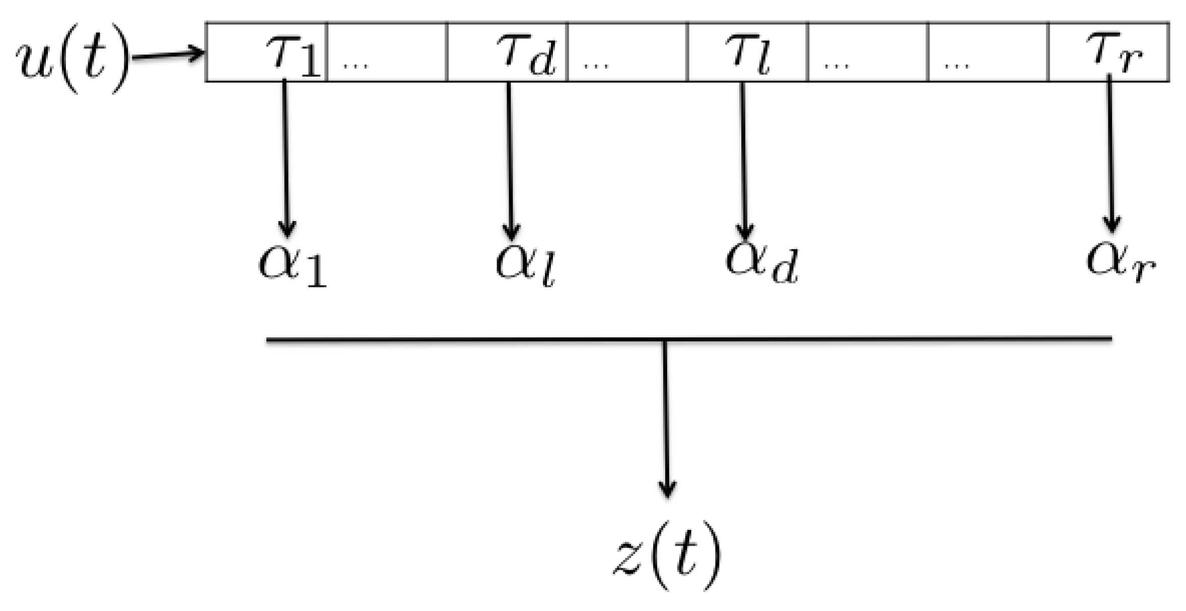
To evaluate the developed scheme, we consider the transmit MMSE, ZFBF, and MRT beamforming of [41]. The implementation of the heuristic beamforming schemes (MRT, ZFBF, transmit MMSE/regularized ZFBF/SLNR-MAX beamforming, and the corresponding power allocation) is also based on the [41]. For the UG MIMO application, instead of randomly generating OTA channels, we use the UG channel impulse response [19], where root mean square (RMS) delay spread, distribution of the RMS delay spread, mean amplitude across multiple profiles for a fixed T-R displacement, effects of soil moisture on peak amplitudes of power delay profiles, mean access delay, and coherence bandwidth statistics are presented based on the measured data collected from UG channel experiments. A realization of the UG channel model is shown in Figure 3. It is important to note here that the calculation of optimal beamforming is not performed in this work because of its computational complexity [41]. The range of the considered SNR values is dB to 30 dB.
For the simulations, the beamforming matrices are generated for sum rates with different beamforming strategies (e.g., MRT, ZFBF, transmit MMSE/regularized ZFBF/SLNR-MAX). Accordingly, UG MIMO evaluation is done for different paths of the underground channel. The direct, lateral, and the reflected paths of the underground channel are considered. After the channel matrices are generated for all realizations, accordingly, for each realization normalized beamforming matrices are computed for each approach. Furthermore, by using the branch-reduce-and-bound (BRB) algorithm, based on the proposed approach, a pre-allocated matrix serves as the feasible starting points for the BRB algorithm.
Accordingly, the system iterates through all powers. Due to its dependency on the transmit power, the normalized beamforming vectors for transmit MMSE beamforming (which is the same as regularized ZFBF and SLNR-MAX beamforming) are also computed similarly. The sum rate is calculated accordingly for the three different beamforming approaches.
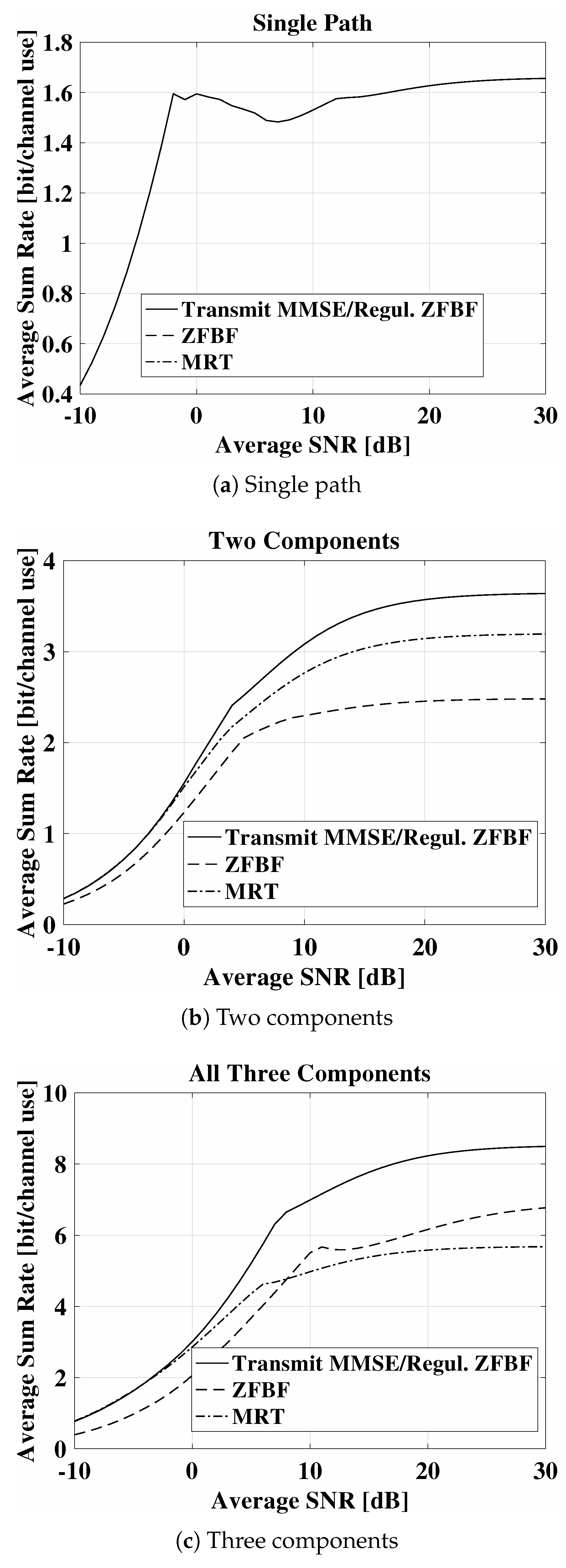
Next, we present the evaluations done using these beamforming approaches for the three different components. In Figure 4, the average sum rate (bit/channel use) is shown as a function of change in average SNR. The case in which only the single (direct) element is considered is shown in Figure 4a. It can be observed that the average sum rate range is to and it does not change significantly with change in average SNR. Therefore, in the case of single component, there is no beamforming involved, and all three approaches have the same average sum rate.
In Figure 4b, the average sum rate for the direct and reflected components (two-component case) is shown. In comparison to the single-path scenario, it can be observed that average sum rate has increased from to at the average SNR value of 10 dB. Moreover, for the two-component case, it can also be observed that the at the lower average SNR of 0 dB, there is only a minor difference of average sum rate between the three beamforming approaches. At the average SNR of 10 dB, the difference between ZFBF and MMSE is increased to , which shows that the UG MIMO approach has the better performance as compared to the ZFBF. This difference further increases with increase in SNR, which shows that in higher SNR regimes, the UG MIMO transmission approach leads to even more improved performance gain.
This better performance of the UG MIMO transmit beamforming improves further in the three-component scenario where all three components (e.g., direct, lateral, and reflected) are used for transmit beamforming. This scenario has been shown in Figure 4c. Overall, the three-component beamforming scenario leads to significant performance improvements as compared to the two-path transmit beamforming case. In comparison to the two-path scenario, it can be observed that average sum rate has increased from to at the average SNR value of 10 dB. Moreover, for the three-component case, it can also be observed that even the at the lower average SNR of 0 dB, there are minor differences of average sum rate between the three beamforming approaches. At the average SNR of 10 dB, the difference between ZFBF and MMSE is increased to . It is also interesting to note that at the average SNR of 30 dB, the average sum rate reached the maximum value of , which shows that the UG MIMO approach performs best when all three components are used for underground transmit beamforming.
5.2. Receive Beamforming
For the receive beamforming of the UG MIMO, a 16-element uniform linear array with interelement distance of half wavelength is used. The operation frequency of 300 MHz is employed. In underground communications, a higher path loss is observed at higher frequencies [19]. The soil has higher permittivity as compared to the air, which leads to the wavelength shortening. Due to the soil permittivity factor, frequency bands in lower spectrum are more suitable for long-range communications. Moreover, distance, depth, and soil water content also affects the path loss in underground communications, which requires environment-aware operation frequency selection.
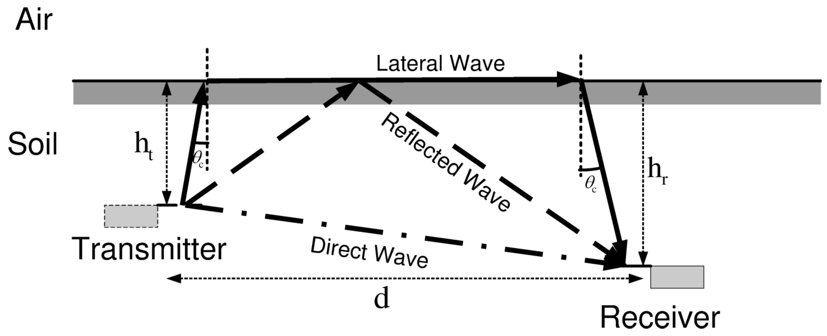
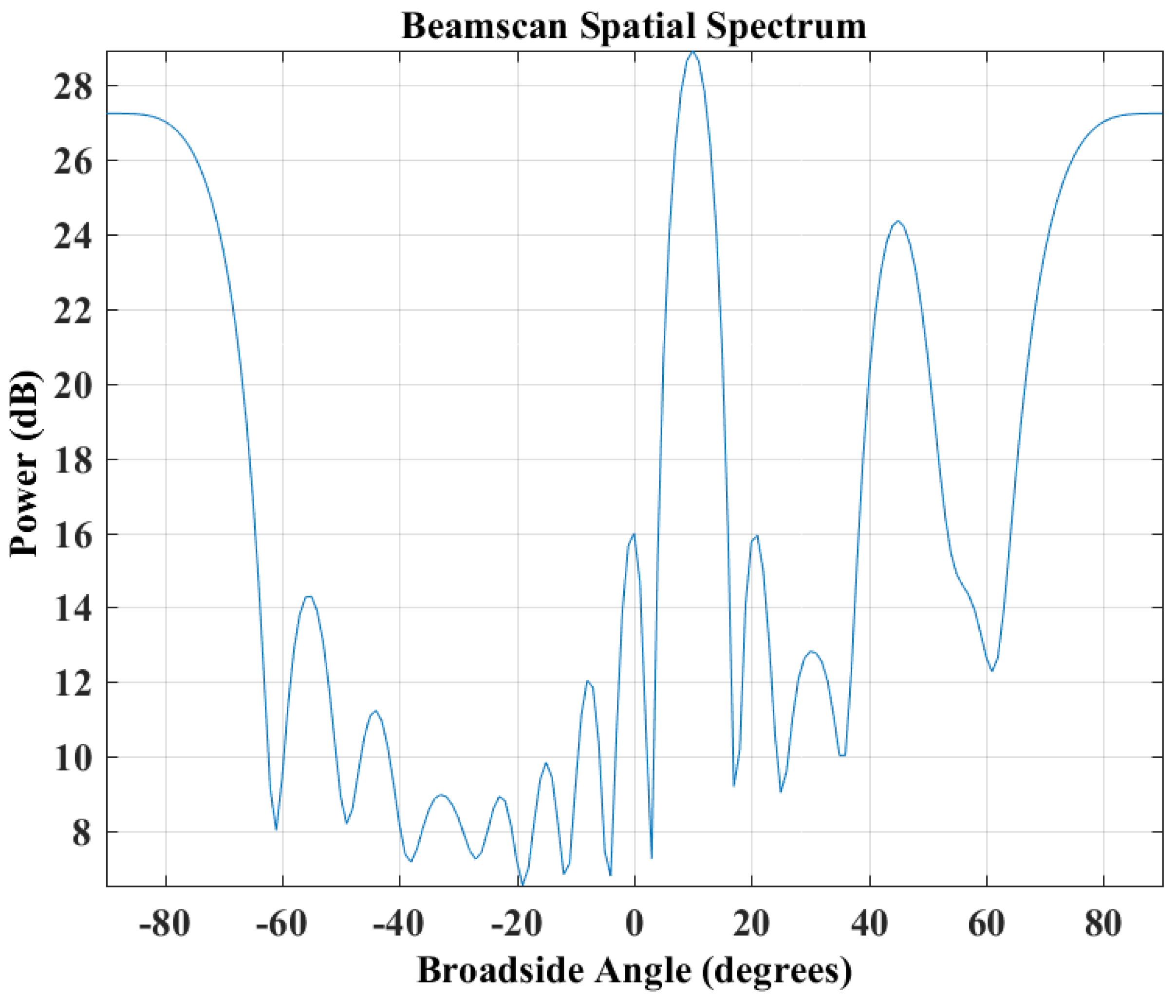
We consider the reception of the received signal through the UG MIMO receive beamforming. In UG communications, there are three main components (e.g., direct, lateral, and reflected (see Figure 5). The received signal that originates from 10–15 azimuth has the highest received power. The UG channel has excess delays extending up to 100 ns and RMS delay spread values up to 50 ns. The attenuation varies over 50 dB dynamic range. The direct wave (second received signal) is received from 90 azimuth (direct path, line-of-sight component). It is also known that arrival time of multipath components follows lateral wave-based 3-wave UG channel model such that the direct wave reaches at the receiver first before the lateral and reflected components for shorter communication distances [19]. The third wave (the reflected signal) travels towards to the soil–air interface and reaches the receiver from 45 azimuth. Its total path is also completely through the soil.
The three received signals at the UG MIMO receiver are not correlated with each other and can be distinguished because of different propagation speed in the stratified soil medium. This leads to different interelement delays that assist different these elements in time. The uniform white noise is considered across all array elements. A beam-scan spatial spectrum estimator is used based on the arrival directions of these three components of the underground channel impulse response.
In Figure 6, the spatial spectrum of the three components in the UG MIMO receive beamforming is shown. The plot shows high power gains at 10 which correspond to the lateral wave. The lower power gain is exhibited at the 90, which represents the direct wave. The lower peak at the 45 indicates the reflected wave due to the lower path in the soil having the lowest gain.
6. Air–Soil Interface Impact Adjustment
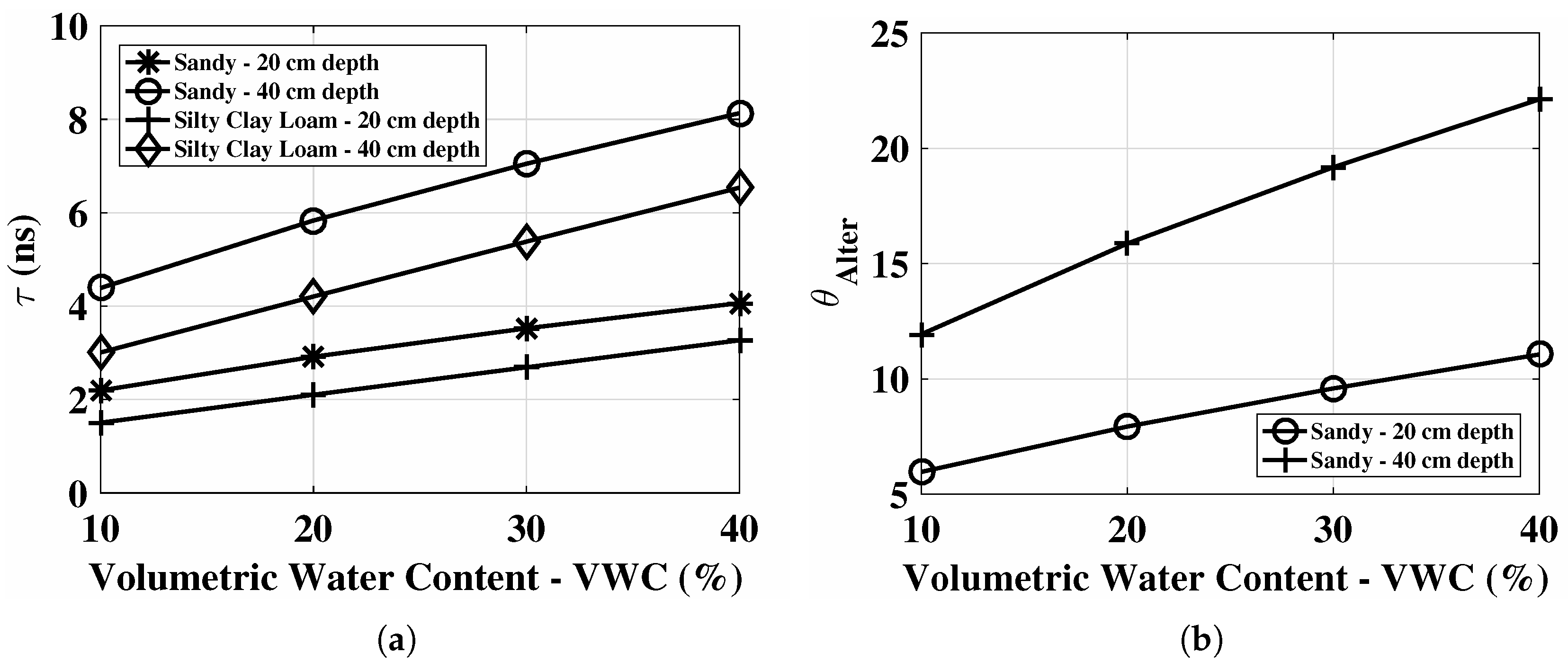
In this section, we discuss the air–soil interface impact adjustment mechanism of the subsurface MIMO, which constitutes the new contribution of this paper as compared with the preliminary conference version [17]. When subsurface beam is directed in isotropic directions particularly to the air–soil interface, the refraction mechanism leads to beam disorientation when incident at the soil–air interface. The soil–air interface separates the soil medium from air, and both have different properties which give rise to the refraction of waves. This phenomenon is also called the beam squint [42]. The resulting error because of beam squint can range from 5 to depending on the amount of soil water content present in the medium. It also depends on the incidence angle at the air–soil interface. The refraction also impacts the wave propagation velocity both in the soil and air medium. This effect can be corrected by using the time delays () and optimum angle adjustment.
In Figure 7a, is shown for 10–40% change in soil moisture values in sandy and silty clay loam soils at 20 cm and 40 cm depth. It can be observed that higher soil moisture levels lead to an increase in delay and it further increases by increasing the depth. The corresponding phase shift adjustment to original phase in sandy soil for 10–40% change in soil moisture at 20 cm and 40 cm depth is shown in Figure 7a. Therefore, larger adjustments are required for higher soil moisture levels and higher depths.
Array Optimization
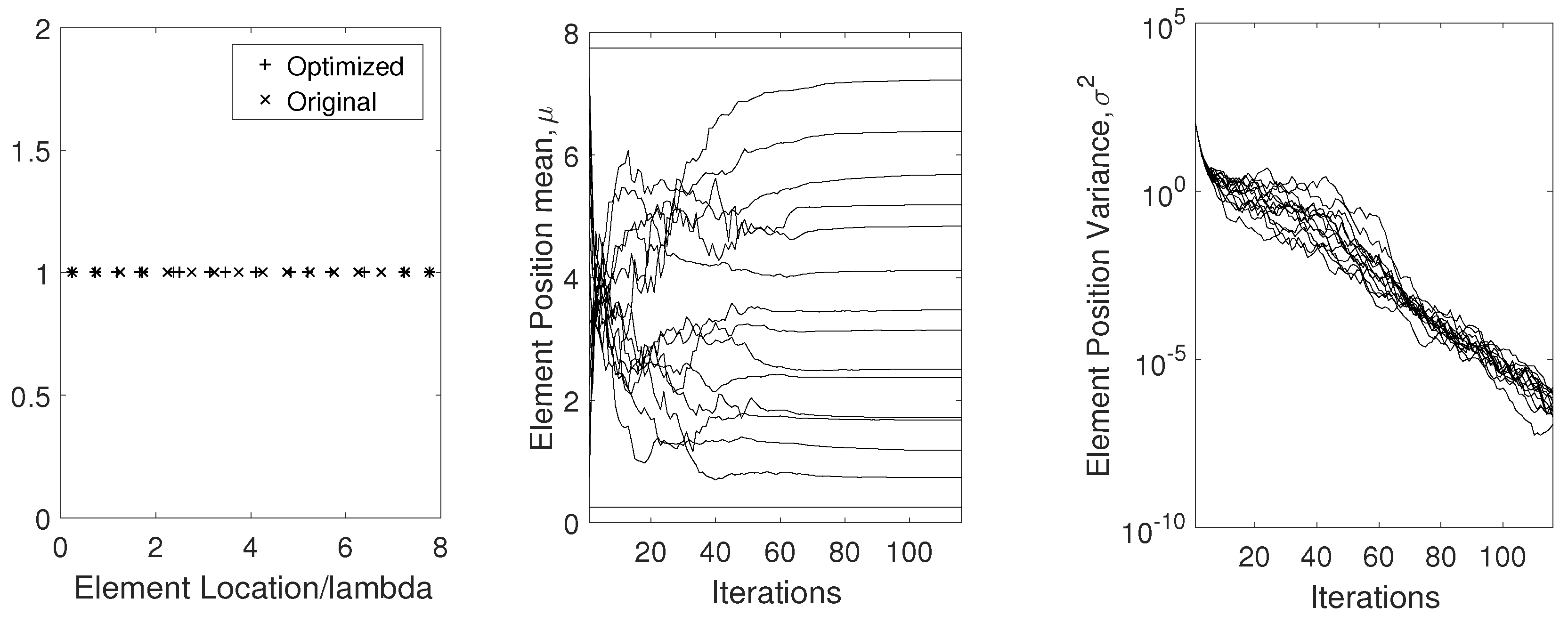
In the UG settings, wavelength variations not only affect the directivity and but also cause grating lobes, which cause beam patterns to appear in undesired directions. We analyze this effect in UG communications. This problem can be solved by either frequency-agile operation to keep the wavelength fixed by using tuning, or by selecting the elements to mitigate the effects of wavelength changes.
The genetic algorithm [42] works on the natural selection process. Overall, this results in complete optimization of array, which is robust to mechanisms taking place in the soil. By using this technique, an initial interelement position can either be specified or chosen arbitrarily. A priori position is based on the actual position without consideration of the particular soil moisture level. Cost (score) function is evaluated and desired interelement spacing is determined. Element position optimization results are shown in Figure 8.
7. Subsurface Phased-Array Implementation
In this section, we discuss software and hardware implementation aspects of the subsurface phased-array implementation.
Software-Defined Implementation: Recent advancements in SDR technology and digital equipment allows efficient implementation of subsurface phased array. Through software-defined control of individual array elements, steering solutions can be used for communications with static and mobile AG devices. Moreover, complex algorithm processing capabilities can be implemented easily. SDR implementation [29] of UG beamforming is challenging due to many reasons. The major challenge is the phase shift between antenna elements. To get a desired beam pattern, the phase shifts between antenna elements needs to be equal in the desired direction. This requires calibration of phase shifters and dynamic on-the-fly synchronization and phase correction to achieve the desired beam.
Digital beamforming based on soil moisture conditions to form dynamic beam patterns can be used. This design consists of a planar array with its own phase shifter with pre-defined parameters for communication with UG and AG arrays. Furthermore, beams can be stitched such that several beam patterns can be determined and designed based on the analyses of UG and AG devices and can be stored in a configuration database for on-demand usage.
Another SDR approach is based on phase shifting in the software. This approach is based on processing in the software-defined radio to adapt to wavelength changes due to soil moisture conditions. The advantage of using this approach is that dynamic changes in the wavelength and phase variations due to UG channel dynamism are compensated without changing physical array arrangements. Moreover, less energy is required in comparison to traditional mechanical phase shifters [39].
Hardware Components: For subsurface phased-array implementation, the hardware array elements can use dipole and printed circuit antennas. Other microwave components such as phase shifters, amplifiers, and dividers, and hybrids can also be implemented as printed circuits through inexpensive equipment [39]. A beamforming network can consist of a stripline configuration. Good wideband characteristics can be achieved within limited underground volume by using a large diameter and close spacing, conducting tubular subsurface phased-array elements. EM simulations can be used for the design of a prototype system. The use of resistive (dummy) elements at the edges of the array can avoid performance degradation at the edge of the array due to abrupt changes. Once the simulated design meets the desired specifications, then an initial array layout configuration can be selected and optimized by observing the performance using a vector network analyzer. A vector network analyzer is used to measure the return loss (antenna reflection coefficients).
8. Conclusions and Future Work
Underground wireless communications in the soil medium is challenging due to the impact of soil texture and soil water content. In subsurface radio-wave propagation, the phased-array antennas can be used to direct the wave power by using the Zenneck waves which leads to underground communication range extension and energy conservation. In this paper, a design of subsurface phased-array antennas for digital agriculture applications has been presented. An UG MIMO technique is developed for transmit and receive beamforming in the underground soil medium. The optimal transmit and receive beamforming vectors under minimal intercomponent interference constraint are derived. It is shown that UG MIMO performs best when all three components of the wireless UG channel are leveraged for beamforming. The environment-aware UG MIMO technique leads to three-fold performance improvements and paves the way for design and development of next-generation sensor-guided irrigation systems in the field of digital agriculture.
The transmit beamforming is used to focus energy in the desired direction. There are three different paths in the underground soil medium through which the waves propagate to reach the receiver. When the UG receiver receives a desired data stream only from the desired path, then the UG MIMO channel becomes a three-path (lateral, direct, and reflected) interference channel. Accordingly, the capacity region of the UG MIMO three-path interference channel and degrees of freedom (multiplexing gain of this MIMO channel) requires careful modeling. Therefore, expressions are required for the degree of freedom of the UG MIMO interference channel. The underground receiver needs to perfectly cancel the interference from the three different components of the EM waves propagating in the soil medium. This concept is based upon reducing the interference of the undesired components to minimum at the UG receiver using the receive beamforming. Accordingly, an underground environment-aware MIMO using transmit and receive beamforming is developed. Moreover, environment-aware UG MIMO techniques are designed and investigated in the underground soil medium.
Any implementation of subsurface phased array is likely to be complicated and expensive as compared to existing solutions. Moreover, practical implementation of subsurface phased array integrated with soil moisture sensing and optimization is a challenging task. For future work, the decreasing cost and complexity of hardware, and using long-range, high-data-rate UG communications, compared to conventional solutions, makes subsurface phased array a viable candidate for next-generation wireless UG communication systems.
Funding
This research received no external funding.
Conflicts of Interest
The authors declare no conflict of interest.
References
- Abrudan, T.E.; Kypris, O.; Trigoni, N.; Markham, A. Impact of Rocks and Minerals on Underground Magneto-Inductive Communication and Localization. IEEE Access. 2016, 4, 3999–4010. [Google Scholar] [CrossRef]
- Akyildiz, I.F.; Stuntebeck, E.P. Wireless Underground Sensor Networks: Research Challenges. Ad Hoc Netw. J. 2006, 4, 669–686. [Google Scholar] [CrossRef]
- Bogena, H.R.; Herbst, M.; Huisman, J.A.; Rosenbaum, U.; Weuthen, A.; Vereecken, H. Potential of wireless sensor networks for measuring soil water content variability. Vadose Zone J. 2010, 9, 1002–1013. [Google Scholar] [CrossRef]
- Dong, X.; Vuran, M.C.; Irmak, S. Autonomous precision agriculture through integration of wireless underground sensor networks with center pivot irrigation systems. Ad Hoc Netw. 2013, 11, 1975–1987. [Google Scholar] [CrossRef]
- Guo, H.; Sun, Z. Channel and Energy Modeling for Self-Contained Wireless Sensor Networks in Oil Reservoirs. IEEE Trans. Wirel. Commun. 2014, 13, 2258–2269. [Google Scholar] [CrossRef]
- Markham, A.; Trigoni, N. Magneto-inductive Networked Rescue System (MINERS): Taking Sensor Networks Underground. In Proceedings of the 11th IPSN ’12, Beijing, China, 16–19 April 2012; pp. 317–328. [Google Scholar]
- Salam, A.; Vuran, M.C.; Irmak, S. Di-Sense: In situ real-time permittivity estimation and soil moisture sensing using wireless underground communications. Comput. Netw. 2019, 151, 31–41. [Google Scholar] [CrossRef]
- Salam, A.; Vuran, M.C.; Dong, X.; Argyropoulos, C.; Irmak, S. A Theoretical Model of Underground Dipole Antennas for Communications in Internet of Underground Things. IEEE Trans. Antennas Propag. 2019, 67, 3996–4009. [Google Scholar] [CrossRef] [Green Version]
- Salam, A. An Underground Radio Wave Propagation Prediction Model for Digital Agriculture. Information 2019, 10, 147. [Google Scholar] [CrossRef]
- Tiusanen, M.J. Soil Scouts: Description and performance of single hop wireless underground sensor nodes. Ad Hoc Netw. 2013, 11, 1610–1618. [Google Scholar] [CrossRef]
- Vuran, M.C.; Salam, A.; Wong, R.; Irmak, S. Internet of underground things in precision agriculture: Architecture and technology aspects. Ad Hoc Netw. 2018, 81, 160–173. [Google Scholar] [CrossRef] [Green Version]
- Vuran, M.C.; Salam, A.; Wong, R.; Irmak, S. Internet of Underground Things: Sensing and Communications on the Field for Precision Agriculture. In Proceedings of the 2018 IEEE 4th World Forum on Internet of Things (WF-IoT 2018), Singapore, 5–8 February 2018. [Google Scholar]
- Akyildiz, I.F.; Sun, Z.; Vuran, M.C. Signal Propagation Techniques for Wireless Underground Communication Networks. Phys. Commun. J. 2009, 2, 167–183. [Google Scholar] [CrossRef]
- Sun, Z.; Wang, P.; Vuran, M.C.; Al-Rodhaan, M.A.; Al-Dhelaan, A.M.; Akyildiz, I.F. Border patrol through advanced wireless sensor networks. Ad Hoc Netw. 2011, 9, 468–477. [Google Scholar] [CrossRef]
- Sun, Z.; Akyildiz, I. Channel modeling and analysis for wireless networks in underground mines and road tunnels. IEEE Trans. Commun. 2010, 58, 1758–1768. [Google Scholar] [CrossRef]
- Sun, Z.; Wang, P.; Vuran, M.C.; Al-Rodhaan, M.A.; Al-Dhelaan, A.M.; Akyildiz, I.F. MISE-PIPE: MI based wireless sensor networks for underground pipeline monitoring. Ad Hoc Netw. 2011, 9, 218–227. [Google Scholar] [CrossRef]
- Salam, A. Underground Environment Aware MIMO Design Using Transmit and Receive Beamforming in Internet of Underground Things. In Proceedings of the 2019 International Conference on Internet of Things (ICIOT 2019), San Diego, CA, USA, 25–30 June 2019. [Google Scholar]
- Salam, A.; Vuran, M.C. Smart Underground Antenna Arrays: A Soil Moisture Adaptive Beamforming Approach. In Proceedings of the IEEE INFOCOM 2017—IEEE Conference on Computer Communications, Atlanta, GA, USA, 1–4 May 2017. [Google Scholar]
- Salam, A.; Vuran, M.C.; Irmak, S. Pulses in the Sand: Impulse Response Analysis of Wireless Underground Channel. In Proceedings of the IEEE INFOCOM 2016—The 35th Annual IEEE International Conference on Computer Communications, San Francisco, CA, USA, 10–14 April 2016. [Google Scholar]
- Salam, A.; Karabiyik, U. A Cooperative Overlay Approach at the Physical Layer of Cognitive Radio for Digital Agriculture. In Proceedings of the Third International Balkan Conference on Communications and Networking 2019 (BalkanCom’19), Skopje, North Macedonia, 10–12 June 2019. [Google Scholar]
- Baranwal, T.; Nitika; Pateriya, P.K. Development of IoT based smart security and monitoring devices for agriculture. In Proceedings of the 2016 6th International Conference-Cloud System and Big Data Engineering (Confluence), Noida, India, 14–15 January 2016; pp. 597–602. [Google Scholar]
- Kisseleff, S.; Akyildiz, I.F.; Gerstacker, W.H. Survey on Advances in Magnetic Induction-Based Wireless Underground Sensor Networks. IEEE Internet Things J. 2018, 5, 4843–4856. [Google Scholar] [CrossRef]
- Suciu, G.; Istrate, C.; Diţu, M. Secure smart agriculture monitoring technique through isolation. In Proceedings of the 2019 Global IoT Summit (GIoTS), Aarhus, Denmark, 17–21 June 2019; pp. 1–5. [Google Scholar]
- Borgia, E. The Internet of Things vision: Key features, applications and open issues. Comput. Commun. 2014, 54, 1–31. [Google Scholar] [CrossRef]
- Tzounis, A.; Katsoulas, N.; Bartzanas, T.; Kittas, C. Internet of Things in agriculture, recent advances and future challenges. Biosyst. Eng. 2017, 164, 31–48. [Google Scholar] [CrossRef]
- Liu, X.; Sheth, A.; Kaminsky, M.; Papagiannaki, K.; Seshan, S.; Steenkiste, P. DIRC: Increasing Indoor Wireless Capacity Using Directional Antennas. In Proceedings of the ACM SIGCOMM, Barcelona, Spain, 17–21 August 2019. [Google Scholar]
- Lakshmanan, S.; Sundaresan, K.; Kokku, R.; Khojestepour, A.; Rangarajan, S. Towards Adaptive Beamforming in Indoor Wireless Networks: An Experimental Approach. In Proceedings of the INFOCOM 2009, Rio de Janeiro, Brazil, 19–25 April 2009. [Google Scholar]
- Kontaxis, D.E.; Tsoulos, G.V.; Athanasiadou, G.E.; Karaboyas, S. Optimality of Transmit Beamforming in Spatially Correlated MIMO Rician Fading Channels. Wirel. Pers. Commun. 2016, 88, 371–384. [Google Scholar] [CrossRef]
- Quitin, F.; Rahman, M.M.U.; Mudumbai, R.; Madhow, U. A Scalable Architecture for Distributed Transmit Beamforming with Commodity Radios: Design and Proof of Concept. IEEE Trans. Wirel. Commun. 2013, 12, 1418–1428. [Google Scholar] [CrossRef]
- Nitsche, T.; Flores, A.B.; Knightly, E.W.; Widmer, J. Steering with eyes closed: Mm-Wave beam steering without in-band measurement. In Proceedings of the IEEE INFOCOM 2015, Kowloon, Hong Kong, 26 April–1 May 2015. [Google Scholar]
- Anand, N.; Lee, S.J.; Knightly, E.W. STROBE: Actively securing wireless communications using Zero-Forcing Beamforming. In Proceedings of the 2012 Proceedings IEEE INFOCOM, Orlando, FL, USA, 25–30 March 2012; pp. 720–728. [Google Scholar]
- Aryafar, E.; Khojastepour, M.A.; Sundaresan, K.; Rangarajan, S.; Knightly, E. ADAM: An Adaptive Beamforming System for Multicasting in Wireless LANs. IEEE/ACM Trans. Netw. 2013, 21, 1595–1608. [Google Scholar] [CrossRef] [Green Version]
- Widrow, B.; Mantey, P.E.; Griffiths, L.J.; Goode, B.B. Adaptive antenna systems. Proc. IEEE 1967, 55, 2143–2159. [Google Scholar] [CrossRef]
- Alexandropoulos, G.C.; Ferrand, P.; Gorce, J.-M.; Papadias, C.B. Advanced coordinated beamforming for the downlink of future LTE cellular networks. IEEE Commun. Mag. 2016, 54, 54–60. [Google Scholar] [CrossRef] [Green Version]
- Du, Y.; Aryafar, E.; Camp, J.; Chiang, M. iBeam: Intelligent client-side multi-user beamforming in wireless networks. In Proceedings of the IEEE INFOCOM 2014, Toronto, ON, Canada, 27 April–2 May 2014. [Google Scholar]
- Kisseleff, S.; Akyildiz, I.F.; Gerstacker, W. Beamforming for Magnetic Induction Based Wireless Power Transfer Systems with Multiple Receivers. In Proceedings of the 2015 IEEE GLOBECOM, San Diego, CA, USA, 6–10 December 2015. [Google Scholar]
- King, R.W.P.; Smith, G. Antennas in Matter; MIT Press: Cambridge, MA, USA, 1981. [Google Scholar]
- Chae, C.B.; Hwang, I.; Heath, R.W.; Tarokh, V. Interference Aware-Coordinated Beamforming in a Multi-Cell System. IEEE Trans. Wirel. Commun. 2012, 11, 3692–3703. [Google Scholar] [CrossRef]
- Fenn, A.; Hurst, P. Ultrawideband Phased Array Antenna Technology for Sensing and Communications Systems; MIT Press: Cambridge, MA, USA, 2015. [Google Scholar]
- Dong, X.; Vuran, M.C. A Channel Model for Wireless Underground Sensor Networks Using Lateral Waves. In Proceedings of the GLOBECOM 2011, Kathmandu, Nepal, 5–9 December 2011. [Google Scholar]
- Björnson, E.; Bengtsson, M.; Ottersten, B. Optimal multiuser transmit beamforming: A difficult problem with a simple solution structure [lecture notes]. IEEE Signal Process. Mag. 2014, 31, 142–148. [Google Scholar] [CrossRef]
- Haupt, R. Timed Arrays; Wiley: Hoboken, NJ, USA, 2015. [Google Scholar]
Figure 1.
An example power delay profile (PDP) of the impulse response model of the wireless UG channel [19].
Figure 1.
An example power delay profile (PDP) of the impulse response model of the wireless UG channel [19].

Figure 2.
The communications schematic for UG MIMO. (a) Transmit Beamforming; (b) Receive Beamforming.
Figure 2.
The communications schematic for UG MIMO. (a) Transmit Beamforming; (b) Receive Beamforming.
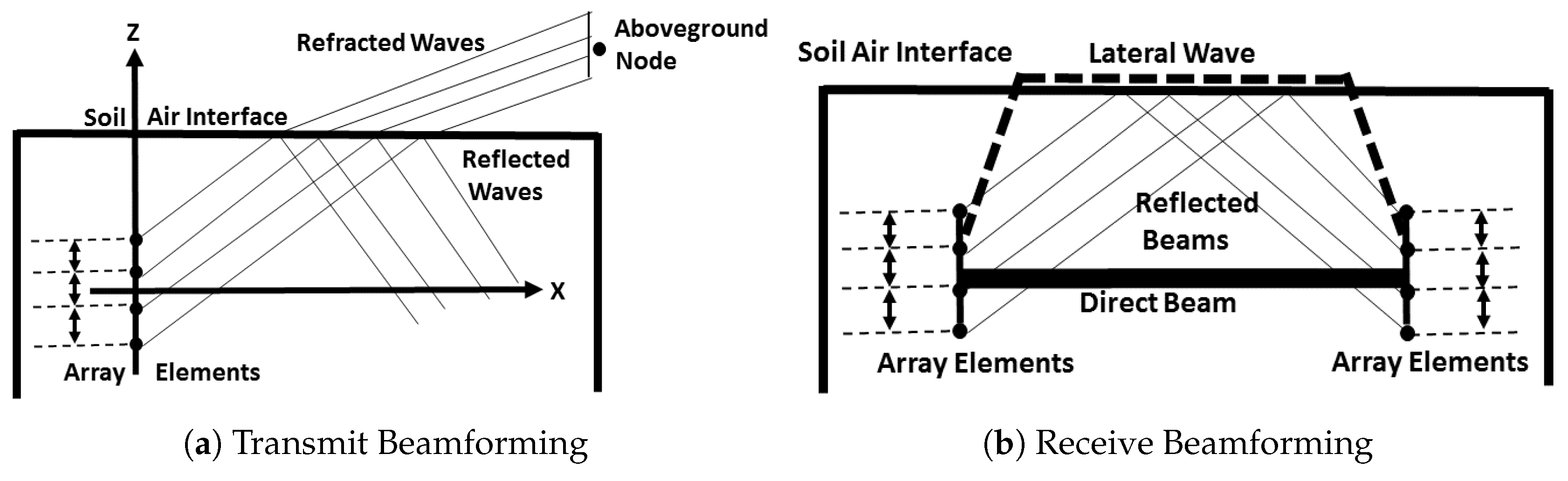
Figure 3.
A realization of the UG channel model with three components.

Figure 4.
UG MIMO: The average sum rate (bit/channel use) as a function of change in average SNR. (a) Single path; (b) two components; (c) three components.
Figure 4.
UG MIMO: The average sum rate (bit/channel use) as a function of change in average SNR. (a) Single path; (b) two components; (c) three components.

Figure 5.
The direct, reflected, and lateral waves in the underground channel [19].
Figure 5.
The direct, reflected, and lateral waves in the underground channel [19].

Figure 6.
The spatial spectrum of the three components of the UG MIMO receive beamforming.

Figure 7.
(a) with 10–40% change in soil moisture in sandy and silty clay loam soils at 20 cm and 40 cm depth. (b) Corresponding phase shift adjustment to original phase in sandy soil for 10–40% change in soil moisture at 20 cm and 40 cm depth.
Figure 7.
(a) with 10–40% change in soil moisture in sandy and silty clay loam soils at 20 cm and 40 cm depth. (b) Corresponding phase shift adjustment to original phase in sandy soil for 10–40% change in soil moisture at 20 cm and 40 cm depth.

Figure 8.
The array optimization results.
© 2019 by the author. Licensee MDPI, Basel, Switzerland. This article is an open access article distributed under the terms and conditions of the Creative Commons Attribution (CC BY) license (http://creativecommons.org/licenses/by/4.0/).
Share and Cite
MDPI and ACS Style
Salam, A. Subsurface MIMO: A Beamforming Design in Internet of Underground Things for Digital Agriculture Applications. J. Sens. Actuator Netw. 2019, 8, 41. https://doi.org/10.3390/jsan8030041
AMA Style
Salam A. Subsurface MIMO: A Beamforming Design in Internet of Underground Things for Digital Agriculture Applications. Journal of Sensor and Actuator Networks. 2019; 8(3):41. https://doi.org/10.3390/jsan8030041
Chicago/Turabian StyleSalam, Abdul. 2019. "Subsurface MIMO: A Beamforming Design in Internet of Underground Things for Digital Agriculture Applications" Journal of Sensor and Actuator Networks 8, no. 3: 41. https://doi.org/10.3390/jsan8030041
Note that from the first issue of 2016, this journal uses article numbers instead of page numbers. See further details here.