Energy Modeling and Power Measurement for Three-Wheeled Omnidirectional Mobile Robots for Path Planning


1
School of Mechanical, Electrical and Information Engineering, Shandong University, Weihai 264209, China
2
Department of Electromechanical Convergence Engineering, Korea University of Technology and Education, Cheonan 31253, Korea
*
Author to whom correspondence should be addressed.
Electronics 2019, 8(8), 843; https://doi.org/10.3390/electronics8080843
Submission received: 29 June 2019
/
Revised: 25 July 2019
/
Accepted: 26 July 2019
/
Published: 28 July 2019
(This article belongs to the Special Issue Renewable Energy Systems for Mobile Robots)
Abstract
:Due to their high mobility, mobile robots (MR) are widely used in intelligent manufacturing. Due to the perfect symmetry of the MR of the three-wheeled moving chassis, it can move quickly in a crowded and complex factory environment. Because it is powered by a lithium battery, in order to improve its energy efficiency, we need to ensure that its power consumption is reduced as much as possible in order to avoid frequent battery replacement. The power consumption of MRs has also become an important research focus for researchers. Therefore, a power consumption modeling of the omnidirectional mobility of the three-wheeled omnidirectional mobile robot (TOMR) is proposed in this paper. When TOMR advances heading at different angles, the speed of each wheel changes dramatically. So, the power consumption of robots will also be greatly changed. In this paper, the energy and power consumption of the robot heading in different directions is analyzed and modeled by formulas. This research can be valuable for path planning and control design.
1. Introduction
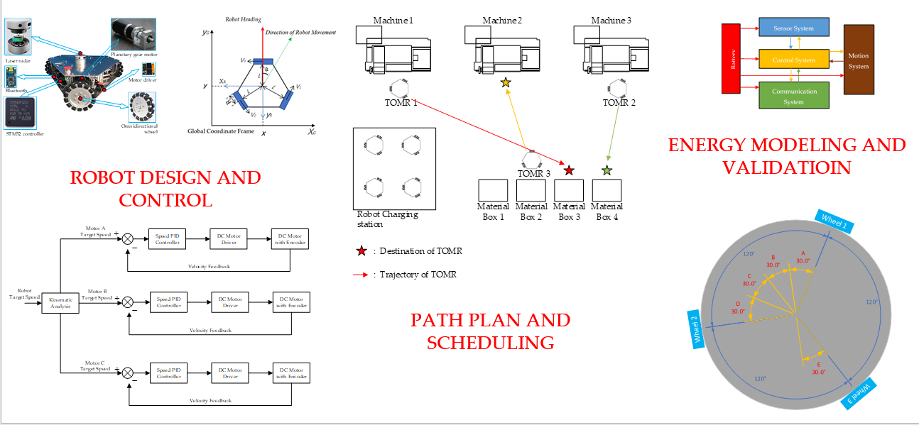
Mobile robots (MR) are used to transport components among machines [1] in intelligent manufacturing [2] which is generally crowded and complex. A Three-wheeled omnidirectional mobile robot (TOMR) can move quickly in any direction because of perfect symmetry, without a complicated turning process [3,4], so they are very suitable for intelligent manufacturing working in a narrow and limited space [5]. In order to carry out path planning and robot control with minimum energy consumption, the energy consumption of the robot’s omnidirectional movement is modeled in this paper. As shown in Figure 1a, a TOMR consists of three omnidirectional wheel assemblies equally spaced at 120 degrees from one another [6].
In order to be suitable for load movement in factories, an MR chassis needs to be designed to have strong load capacity, anti-vibration, and good stability [7,8]. The schematic diagram of TOMR is shown in Figure 1b. Large omnidirectional wheels and suspension systems [9] can ensure that MR’s payload capacity reaches 50 kg. Because this paper focuses on the power consumption of TOMR in omnidirectional movement, Figure 1b is only a sketch of TOMR, showing the composition of TOMR energy-consuming components, not a complete transport robot that can be used in an intelligent manufacturing factory.
Scheduling the different tasks assigned to the MR and maximizing the efficiency of the implementation is critical [10] to intelligent manufacturing. TOMRs are chosen as target platforms due to their flexibility and versatility [6]. Also, TOMR’s mobile control is an important research field. In order to better control TOMRs, researchers have proposed a variety of control methods [11,12,13], because the control of the mobile robot is the core of path planning and energy reduction. We need to make full use of the advantage that TOMRs can move in any direction, which could obviously reduce the space occupation and have a higher moving speed.
At present, the power consumption model of rechargeable lithium batteries has been sufficiently analyzed, but there are few articles on the analysis and modeling of the power consumption of robots in the process of moving. By establishing the relationship between the power consumption of each subsystem, the optimal algorithm to reduce the energy consumption of the robot can be obtained [14]. If the power consumption of the robot can be modeled, the power consumption system of the robot can be perfected and the power consumption of the robot can be accurately predicted. By programming the complete robot power consumption model into the control system, the control system can calculate and predict the power consumption during the robots running process, which can help the robot to perform path planning and find the path with the lowest energy consumption during the robot’s travel.
MR for use in automation in intelligent manufacturing plants require the ability of environmental awareness, self-diagnosis, automatic mobility, information exchange, etc. [15,16,17]. So, the energy consumption of MRs comes from four subsystems of MR: Motion system, control system, sensor system, and communication system, as shown in Figure 2.
After the energy model of MR is formulated [18,19,20], the power consumption of the four robotic subsystems can be calculated by the power consumption model. By establishing the relationship between the power consumption of each subsystem, the optimal algorithm to reduce the energy consumption of the robot can be obtained [14].
Applying it to the Robot Operating System (ROS) programming can effectively reduce the energy consumption of mobile robots by choosing the correct control method and the lowest energy consumption path through the power model to reduce the energy consumption of the robot. This paper provides a model for the power consumption of the omnidirectional wheel and the omnidirectional movement.
2. Related Works
With the rapid development of intelligent manufacturing and the extensive use of MRs, the question of how to reduce the energy consumption of MRs in unmanned factories has attracted a lot of attention. Generally speaking, there are four ways to reduce MR’s energy consumption.
The first is to optimize the mechanical structure of the robot to reduce power consumption. Many studies on the mechanical structures of TOMRs have been performed. Structures such as omni-wheels and omnidirectional robot systems are common [21]. Numerous studies on the mechanical structures of TOMRs, such as omni-wheels and omnidirectional robot systems, have been performed [22,23,24]. The second is to reduce the power consumption through the low power design of the robot’s control system and sensor system, and the use of low power components. To reduce the power consumption of robotic electronic components is considered by many researchers to be an important goal. Mei et al. [25] studied the components of MR in energy-efficient designs. Energy-efficient motion planning methods have been applied to reduce the energy consumption of mobile robots. MRs reduce energy consumption by finding the shortest path [26]. Bartlett et al. proposed a probabilistic, data-driven approach to estimating the energy consumption of a mobile robot on a set of trajectories, whether they have been traversed or not [27]. Sun et al. [28] take into account friction and gravity in finding energy-efficient paths across a terrain. Kim and Kim [29] showed theoretically that the energy efficiency of translational motion for wheeled mobile robots can be improved by varying the velocity profile of the motor, where instead of applying constant acceleration and deceleration, variable acceleration and deceleration are applied as the robot starts to move or stop. In this way, an improvement of up to 30% in efficiency was achieved.
The fourth is to improve the power consumption model of the robot which can be applied in ROS, and to reduce energy consumption by programming to select the optimal efficiency strategy. Kai Eggers et al. [30] presents an approach to significantly improve modeling accuracy for the power and energy demands of industrial robots. Otsu and Kubota [31] presented a self-supervised approach for the mobile robot which considers terrain geometry and soil types.
3. Power Consumption Modeling of TOMR
The three wheels of TOMR are completely symmetrical as shown in Figure 3. The three wheels of TOMR are distributed according to the strict symmetrical structure of 120 degrees. This structure enables TOMR to move in any direction within 360 degrees. The 360-degree orientation can be divided into three identical 120-degree ranges and the three ranges are completely symmetrical. The 120-degree angle between any two wheels can be divided into four 30-degree angles. Because of the symmetrical structure, the four 30-degree angles are also symmetrical in terms of the forward direction and energy consumption of TOMR. The power consumption of the B part equivalent to E, and the power consumption of the E part is equivalent to A, so the energy consumption measurement range of TOMR can finally be reduced to 30 degrees.
It is found through measurement that the power consumption of TOMR has a great relationship with the speed at which it runs stably, so we first model the speed. The method of modeling the speed is to first measure the speed of the TOMR by the vehicle-mounted encoder, and then model and analyze the measured data.
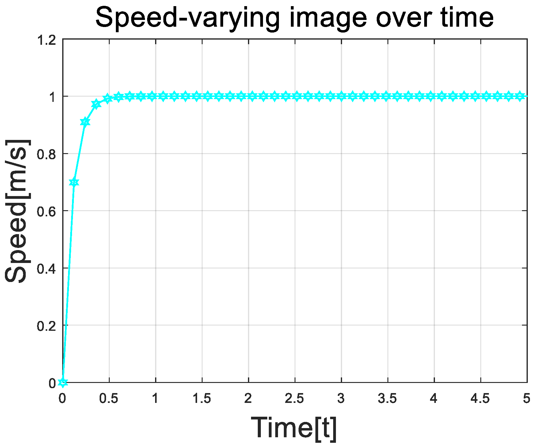
In order to ensure the accuracy of the experiment, we have unified the maximum speed of the robot. In this experiment, the maximum speed of the robot is specified as 1 m/s, which can guarantee the speed variation of our robot when starting at different angles. The speed values after stabilization are the same, so that the difference in TOMR power consumption when starting at different angles is more accurately studied.
The speed image of the robot under test conditions is shown in Figure 4.
After the measurement, it can be found that the speed of TOMR changes very sharply during the start-up process. As the speed increases, the acceleration of TOMR gradually decreases, and finally, it can stabilize at 1 m/s, which is the maximum speed of the robot we set, which indicates that the PID algorithm we set can stabilize the speed at the set value in a short time. The maximum speed we set for TOMR is valid, and TOMR can move according to our settings.
is the energy consumed during the TOMR movement, is the energy consumed by the motion system during the TOMR movement, is the energy consumed by the control system during exercise, is the energy consumed by the sensing system during exercise, and is the energy consumed by the communication system.
According to our research and analysis of robot power consumption, we divide the power consumption of TOMR into four parts, namely , , , and for analysis and research.
3.1. Motion System Modeling
Through the research and analysis of the motion system, we divided the motion system into five parts, focusing on the power consumption from the start of the speed to the steady operation of the speed when moving at different angles. For the measurement of the power consumption of the motion system, we used the American Itech IT6952A for measurement. This product is capable of measuring the power consumption of our motion system.
is the energy consumed by the motion system during the TOMR movement, is the power consumption of the motion system during exercise.
In the article, two coordinate systems are established as shown in Figure 1a. One is the robot coordinate system and the other is the global coordinate system. The robot coordinate system is built for the robot, and the position of the robot coordinate system relative to the robot is never changed. The global coordinate system is globally established, and the global coordinate system does not change with the movement of the robot. In the measurement of the speed , the measurement is performed in the global coordinate system. The main function of the robot coordinate system is to decompose the overall speed of the robot to help solve the speed of each drive wheel of the robot.
γ is the angle between the speed direction of the robot and the positive X-axis direction of the robot coordinate system, is the value of the actual speed of the robot. are the components of X and Y axes of the translation speed of the robot in the coordinate system of the robot body.
is the line speed of three driving wheels. is the angular velocity of the three drive wheels, respectively. is the angular velocity of the robot’s rotation. l1, l2, l3 is the horizontal distance from the geometric center of the car body to the center of the three wheels. is the radius of the wheel [32].
is the work that the frictional force that cancels each other out during the TOMR movement. is the weight of the TOMR, is the friction coefficient of TOMR, is the angle between the orientation of the TOMR and the direction of motion of the robot. , , is the speed of the three wheels of the robot, The coefficients and correspond to friction due to roll and skid forces, respectively.
is the work done to overcome the frictional resistance during the advancement, v is the current speed of TOMR, is the friction coefficient of TOMR.
is the mechanical dissipation during the movement and the dissipation of the motor itself. is the radius of the omnidirectional wheel. is the speed coefficient during the start of the robot. is the speed parameter during TOMR startup.
is the power consumption dissipated in the form of thermal energy. and are the temperature coefficient constants of the motor, is the temperature coefficient of the resistance, and is the speed constant of the motor. is the speed coefficient of the thermal energy dissipation of the robot.
is the increase of the kinetic energy of the robot during the movement.
The energy dissipated by the friction forces in the course of movement is shown in Figure 5a. The energy dissipated by the friction forces in the course of movement
The energy consumed by overcoming the friction resistance in the course of advance is shown in Figure 5b. The mechanical dissipation and the motor itself dissipation in the course of movement is shown in Figure 5c:
The change of kinetic energy EK during TOMR motion is shown in Figure 6a and the dissipated energy in the form of thermal energy is shown in Figure 6b.
The parameters of the motor and drive wheel of the measuring robot are shown in Table 1
In order to test the effect of this model on the power consumption modeling of the TOMR motion system, we compare the modeled values of the motion system with the actual values and calculate the corresponding deviations. The results are shown in Table 2.
The table above shows the comparison between the modeled values of the robot’s motion system and the measured values of the motion system. From the above table, we can see that our modeling is more accurate. The error between the measured values is within 6%, and our modeling is successful within the tolerances.
3.2. Control System Modeling
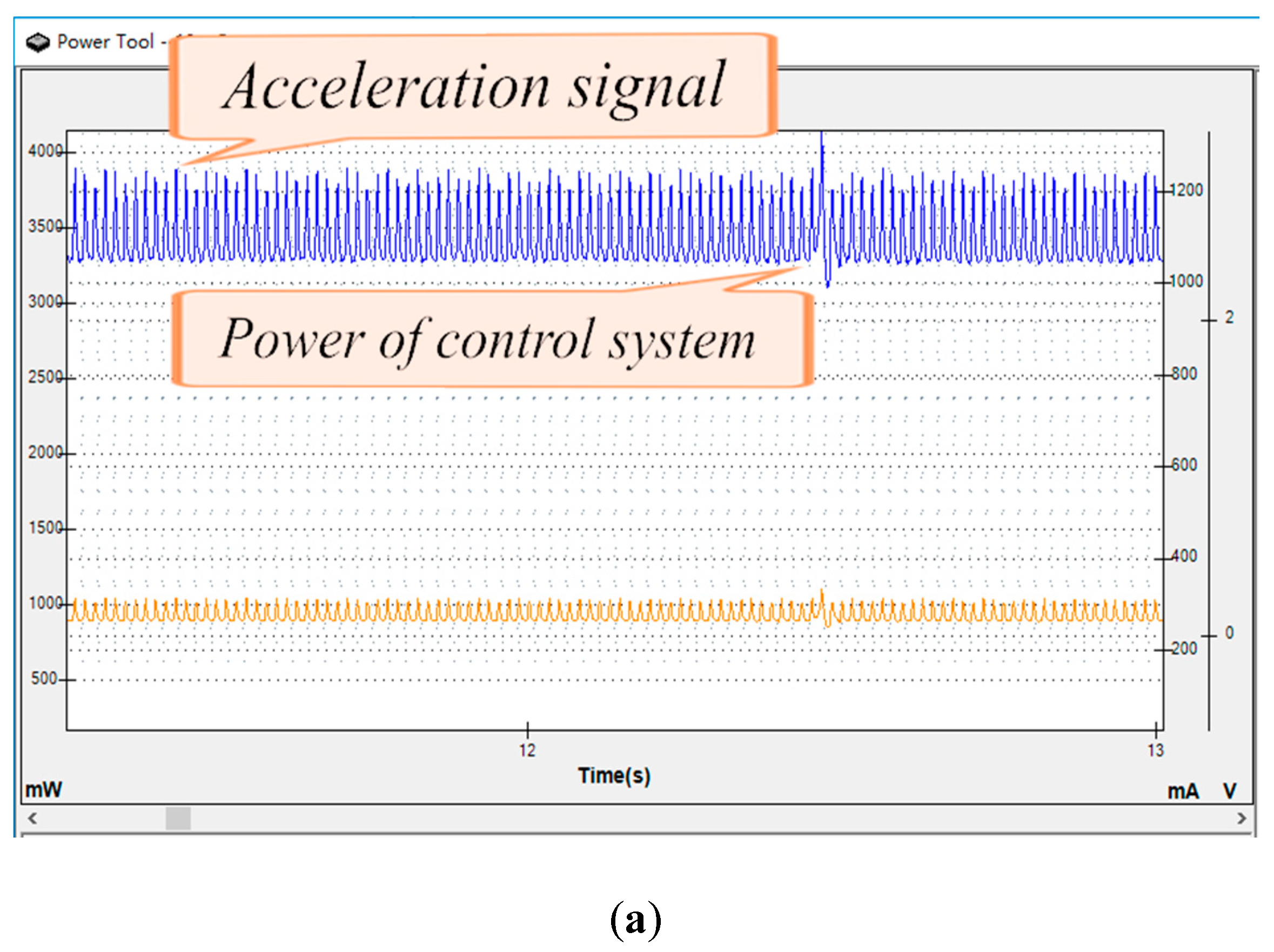
Equation (15) is the power consumption model of the control system. and is the speed constant of the control system. The power consumption of the TOMR control system is shown in Figure 7. Figure 7a shows the power consumption of the robot starting at an angle of 30 degrees is the greatest when the robot’s wheels counteract each other. At the same time, the speed of each driving wheel is relatively the greatest, so the power consumption of the robot control system is the greatest and the acceleration pulse is the most intensive. Figure 7b shows the power consumption of the control system when the robot starts at an angle of 0 degrees. The control system at this time has the lowest power consumption. Figure 7c shows the power consumption of the robot near the steady speed.
After measurement, it is found that the power consumption of the control system is mainly related to the acceleration of the robot. When the robot starts from the speed of 0, the robot needs to send an acceleration pulse to accelerate. At this time, the acceleration pulse sent by the robot’s control system is very dense. The speed of the robot gradually increases. At this time, the acceleration of the robot becomes smaller and smaller, and the intensity of the acceleration pulse of the robot at this time is increased. As the acceleration value decreases, as the acceleration pulse of the robot decreases, the power consumption currently becomes smaller and smaller.
In addition, the power consumption of the robot’s control system is also related to the angle at which the robot is started, because the number of motors that the robot needs to start during the start-up process and the speed at which each motor starts at different angles are different, so the power consumption of the robot control system has a lot to do with the starting angle of the robot.
4. Experiment Setup and Result
This experiment is used to simulate a real factory environment. Place the robot in a preset environment, and then adjust the robot for starting conditions. The power consumption modeling of the above robot has been programmed into the robot’s control system. During the experiment, the experimenter sends the angle to the robot through the serial port. The robot calculates the speed of the three drive wheels by the above formula, and the PID control system is then used to control the robot to proceed according to the experimenter’s settings.
During the experiment, we recorded the trajectory of the robot on the ground. The error between the motion path of the robot and the preset path is measured to ensure that the robot moves according to the preset path. After measuring the error between the robot’s motion path and the preset path, the error in deviation from the path did not exceed 0.02 degrees. At the same time, each part of the experiments are no longer powered by battery power. Instead, we used our professional experimental power supply equipment to supply power. The power at this time was recorded to ensure the analysis in our subsequent process. After the experiment is completed, we analyzed the trajectory of the robot during the experiment, analyzed the accuracy of the robot in the process of moving, and the deviation error in the moving process.
After measuring the power stability value of TOMR starting from different angles as shown in Figure 8, we can see that TOMR fully conforms to our model through two comparison graphs, and the power consumption of robots was the highest when starting at 30 degrees, and after our measurement, it was found that the power consumption of TOMR matched our expectations. The robot’s power distribution was uniform and symmetrical.
In order to verify the law of robot symmetry, we increased the experimental range to 60 degrees and measured the power consumption during the movement of the TOMR within 60 degrees. After measuring, the power consumption of the robot was consistent with the analysis of the power consumption of the robot when we started. It only needed to measure the power consumption of TOMR within 30 degrees. The rest of the angle is completely symmetrical with the power consumption within the 30-degree range.
In the process of power consumption measurement, A Monsoon solution AAA10F power monitor was used to measure the electrical power of the sensor system, control system, and communication system. ITECH IT6952A was used to measure the electrical power of the motion system as well as the total power consumption.
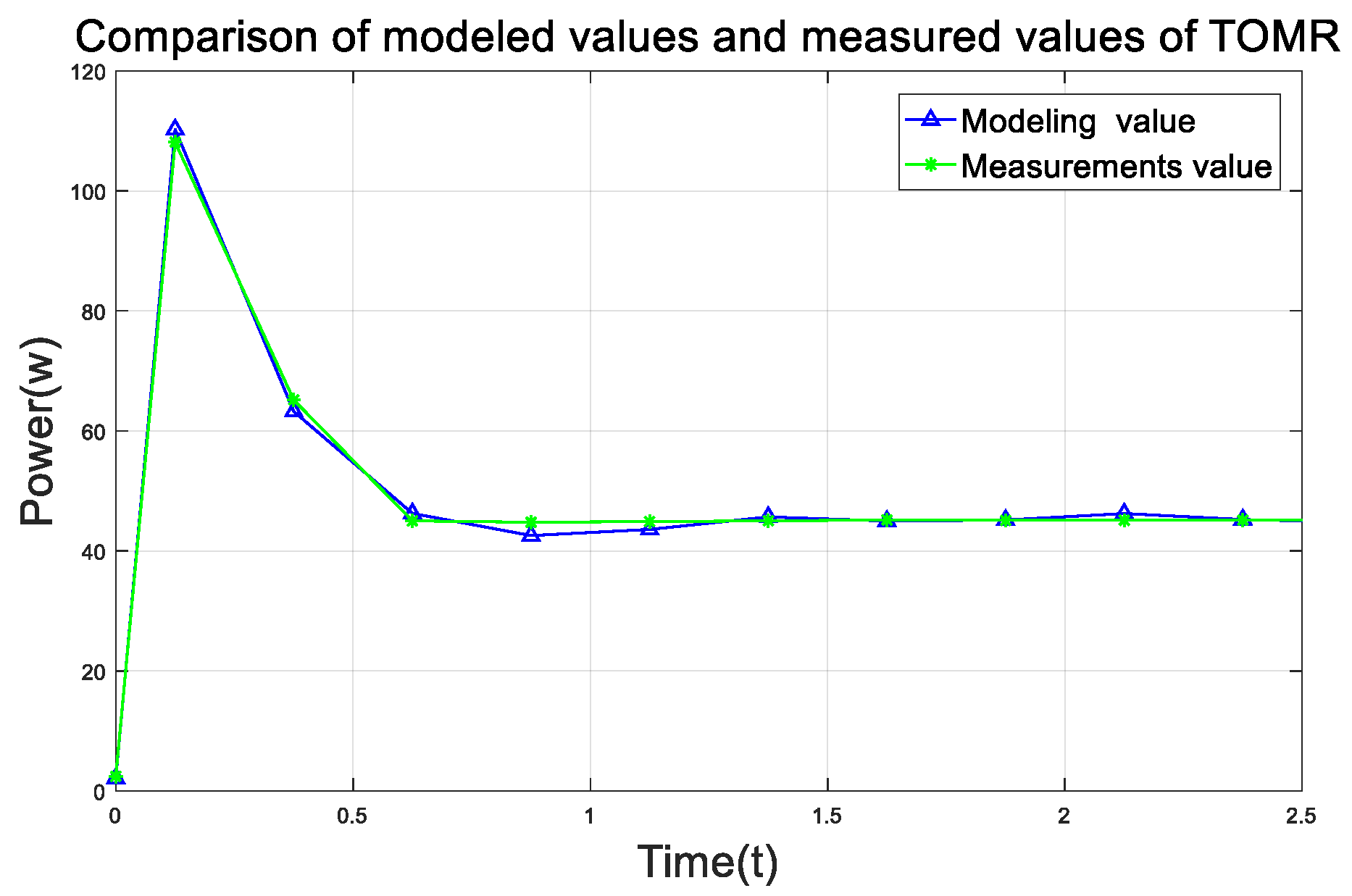
In order to show more intuitively the relationship between the actual measured power consumption and the modeling power consumption of the robot, we chose to compare the robot to the actual measured value and the modeling power consumption value in the course of the motion at an angle of 20 degrees, as shown in Figure 9.
Through Table 2 and Figure 9, we can see that the change rule of the modeled value is consistent with the actual measurement value. Through Table 2, we can see that the error between the actual measurement value of TOMR and the modeled value is less than 7%. The TOMR model is correct within the allowable range of errors.
5. Conclusions and Future Work
In this paper, we analyzed the application of TOMR in un-manned, intelligent-manufacturing factories. The control method and power consumption characteristics of the omnidirectional wheel robot’s movement were studied. TOMR was completely symmetrical and the omnidirectional wheeled robot can realize omnidirectional movement, which ensures that TOMR can transport goods in the complex environment of an unmanned factory without orientation. The energy consumption of TOMR moving in any direction is modeled and verified by experiments under the constraints of an unmanned factory. This model can be used to calculate and predict the energy consumption of TOMR, which provides a guide to facilitate the energy-efficient strategies through programming in ROS. We studied the control of the omnidirectional movement of the TOMR and the power consumption of the TOMR during the omnidirectional movement according to the complete symmetry of TOMR’s three omnidirectional wheels. For detailed analysis, we verified both the control theory and the experimental measurement. The result shows that the error between the TODR power consumption modeling value and the actual value can be controlled within 7%.
By modeling the power consumption of the omnidirectional movement, we can accurately calculate and predict the energy consumption of TOMR during the movement process. The purpose of TOMR modeling is to model the power of the path during the TOMR movement and then use the model to find the path with the lowest power consumption.
At present, our knowledge aim at modeling the power consumption of TOMR in the process of omnidirectional movement, but it does not model the power consumption of other states in the TOMR motion such as the in-situ rotation of TOMR. We have only studied the energy consumption of TOMR at the start-up stage in any direction. The next research stage is to compare the energy consumption of two kinds of turning modes: Turning in place before moving forward and turning while moving forward to find the lowest energy consumption models of the different turning modes, then summarize and analyze the power consumption of multiple states, and finally choose a path with the smallest power consumption in a complex environment when linear motion is restricted.
Author Contributions
Conceptualization, J.K.; data curation, L.H.; formal analysis, L.Z.; methodology, L.Z.; project administration, L.Z.; resources, J.K.; software, L.H.; supervision, J.K.; validation, L.H.; writing—original draft, L.H.; writing—review and editing, L.Z.
Funding
This research received no external funding.
Conflicts of Interest
The authors declare no conflict of interest.
References
- Dang, Q.V.; Nguyen, C.T.; Rudová, H. Scheduling of mobile robots for transportation and manufacturing tasks. J. Heuristics 2018, 25, 175–213. [Google Scholar] [CrossRef]
- Kusiak, A. Editorial: Intelligent manufacturing: Bridging two centuries. J. Intell. Manuf. 2019, 30, 1–2. [Google Scholar] [CrossRef]
- Pin, F.; Killough, S. A new family of omnidirectional and holonomic wheeled platforms for mobile robots. IEEE Trans. Robot. Autom. 1994, 10, 480–489. [Google Scholar] [CrossRef]
- Kim, K.B.; Kim, B.K. A new approach to time-optimal straight-line trajectory for omni-directional mobile robots with multi-objective costs. In Proceedings of the 2010 IEEE International Conference on Robotics and Automation, Anchorage, Alaska, 3–8 May 2010. [Google Scholar]
- Kim, H. Minimum-energy cornering trajectory planning with self-rotation for three-wheeled omni-directional mobile robots. Int. J. Control. Autom. Syst. 2017, 15, 1857–1866. [Google Scholar] [CrossRef]
- Kim, H.; Kim, B.K. Minimum-energy trajectory generation for cornering with a fixed heading for three-wheeled omni-directional mobile robots. J.Intell. Robot. Syst. 2014, 75, 205–221. [Google Scholar] [CrossRef]
- Qian, J.; Zi, B.; Wang, D.; Ma, Y.; Zhang, D. The Design and Development of an Omni-Directional Mobile Robot Oriented to an Intelligent Manufacturing System. Sensors 2017, 17, 2073. [Google Scholar] [CrossRef] [PubMed]
- Roh, S.G.; Lim, B. Flexible Suspension Mechanism for Stable Diving of a Differential Drive Mobile Robot. In Proceedings of the 2013 IEEE/RSJ International Conference on Intelligent Robots and Systems, Tokyo, Japan, 3–7 November 2013; pp. 5518–5523. [Google Scholar]
- Maddahi, Y.; Sepehri, N.; Maddahi, A.; Abdolmohammadi, M. Calibration of wheeled mobile robots with differential drive mechanisms: an experimental approach. Robot 2012, 30, 1029–1039. [Google Scholar] [CrossRef]
- Dang, Q.V.; Nguyen, L. A heuristics approach to schedule mobile robots in flexible manufacturing environments. Procedia CIRP 2016, 40, 390–395. [Google Scholar] [CrossRef]
- Byun, K.-S.; Song, J.-B. CVT control of an omnidirectional mobile robot with steerable omnidirectional wheels for energy efficient drive. In Proceedings of the IEEE International Conference on Robotics and Automation, Taipei, Taiwan, 14–19 September 2003; pp. 503–508. [Google Scholar]
- Ribeiro, F.; Moutinho, I.; Silva, P.; Fraga, C.; Pereira, N. Three Omni-Directional Wheels Control on a Mobile Robot, Control 2004; University of Bath: Bath, UK, 2004. [Google Scholar]
- Huang, H.-C.; Tsai, C.-C. FPGA implementation of an embedded robust adaptive controller for autonomous omnidirectional mobile platform. IEEE Trans. Ind. Electron. 2009, 56, 1604–1616. [Google Scholar] [CrossRef]
- Hou, L.; Zhang, L.; Kim, J. Energy Modeling and Power Measurement for Mobile Robots. Energies 2019, 12, 27. [Google Scholar] [CrossRef]
- Galasso, F.; Rizzini, D.L.; Oleari, F.; Caselli, S. Efficient calibration of four wheel industrial AGVs. Robot. Comput. -Integr. Manuf. 2019, 57, 116–128. [Google Scholar] [CrossRef]
- Thoben, K.D.; Wiesner, S.; Wuest, T. “Industrie 4.0” and Smart Manufacturing–A Review of Research Issues and Application Examples. Int. J. Autom. Technol. 2017, 11, 4–16. [Google Scholar] [CrossRef]
- Peng, T.; Qian, J.; Zi, B.; Liu, J.; Wang, X. Mechanical Design and Control System of an Omni-directional Mobile Robot for Material Conveying. Procedia Cirp 2016, 56, 412–415. [Google Scholar] [CrossRef] [Green Version]
- Xie, L.; Henkel, C.; Stol, K.; Xu, W. Power-minimization and energy-reduction autonomous navigation of an omnidirectional Mecanum robot via the dynamic window approach local trajectory planning. Int. J. Adv. Robot. Syst. 2018, 15, 15. [Google Scholar] [CrossRef]
- Kim, H.; Kim, B.K. Minimum-energy trajectory planning and control on a straight line with rotation for three-wheeled omni-directional mobile robots. In Proceedings of the IEEE International Conference on Intelligent Robots and Systems, Vilamoura, Portugal, 7–12 October 2012; pp. 3119–3124. [Google Scholar]
- Canfield, S.L.; Hill, T.W.; Zuccaro, S.G. Prediction and Experimental Validation of Power Consumption of Skid-Steer Mobile Robots in Manufacturing Environments. J. Intell. Robot. Syst. 2018, 94, 825–839. [Google Scholar] [CrossRef]
- Sharbafi, M.A.; Lucas, C.; Daneshvar, R. Motion Control of Omni-Directional Three-Wheel Robots by Brain-Emotional-Learning-Based Intelligent Controller. IEEE Trans. Syst. Man Cybern. Part C Appl. Rev. 2010, 40, 630–638. [Google Scholar] [CrossRef]
- Indiveri, G. Swedish wheeled omnidirectional mobile robots: Kinematics analysis and control. IEEE Trans. Rob. 2009, 25, 164–171. [Google Scholar] [CrossRef]
- Diegel, O.; Badve, A.; Bright, G.; Potgieter, J. Improved Mecanum wheel design for omni-directional robots. In Proceedings of the 2002 Australian Conference on Robotics and Automation, Auckland, New Zealand, 27–29 November 2002; pp. 117–121. [Google Scholar]
- Salih, J.E.M.; Rizon, M.; Yaacob, S. Designing omni-directional mobile robot with mecanum wheel. Am. J. Appl. Sci. 2006, 3, 1831–1835. [Google Scholar]
- Mei, Y.; Lu, Y.H.; Hu, Y.C.; Lee, C.G. A case study of mobile robot’s energy consumption and conservation techniques. In Proceedings of the IEEE 12th International Conference on Advanced Robotics, Piscataway, NJ, USA, 18 July 2005; pp. 492–497. [Google Scholar]
- Kim, Y.; Kim, B.K. Time-optimal cornering trajectory planning for differential-driven wheeled mobile robots with motor current and voltage constraints. In Proceedings of the 2013 IEEE International Symposium on Industrial Electronics, Taipei, Taiwan, 28–31 May 2013. [Google Scholar]
- Bartlett, O.; Gurau, C.; Marchegiani, L.; Posner, I. Enabling intelligent energy management for robots using publicly available maps. In Proceedings of the 2016 IEEE/RSJ International Conference on Intelligent Robots and Systems (IROS), Daejeon, Korea, 9–14 October 2016; pp. 2224–2229. [Google Scholar]
- Sun, Z.; Reif, J. On finding energy-minimizing paths on terrains. IEEE Trans. Robot. 2005, 21, 102–114. [Google Scholar] [Green Version]
- Kim, C.H.; Kim, B.K. Energy-saving 3-step velocity control algorithm for battery-powered wheeled mobile robots. In Proceedings of the IEEE 12th International Conference on Advanced Robotics, Barcelona, Spain, 18–22 April 2005; pp. 2375–2380. [Google Scholar]
- Eggers, K.; Knochelmann, E.; Tappe, S.; Ortmaier, T. Modeling and experimental validation of the influence of robot temperature on its energy consumption. In Proceedings of the 2018 IEEE International Conference on Industrial Technology (ICIT), Lyon, France, 19–22 February 2018; pp. 239–243. [Google Scholar]
- Otsu, K.; Kubota, T. Energy-Aware Terrain Analysis for Mobile Robot Exploration. In Field and Service Robotics; Springer: New York, NY, USA, 2016. [Google Scholar]
- Hacene, N.; Mendil, B. Motion Analysis and Control of Three-Wheeled Omnidirectional Mobile Robot. J. Control. Autom. Electr. Syst. 2019, 30, 194–213. [Google Scholar] [CrossRef]
Figure 1.
Three-wheeled omnidirectional mobile robot (TOMR). (a) Schematic of TOMR and (b) schematic diagram of robot architecture.
Figure 1.
Three-wheeled omnidirectional mobile robot (TOMR). (a) Schematic of TOMR and (b) schematic diagram of robot architecture.
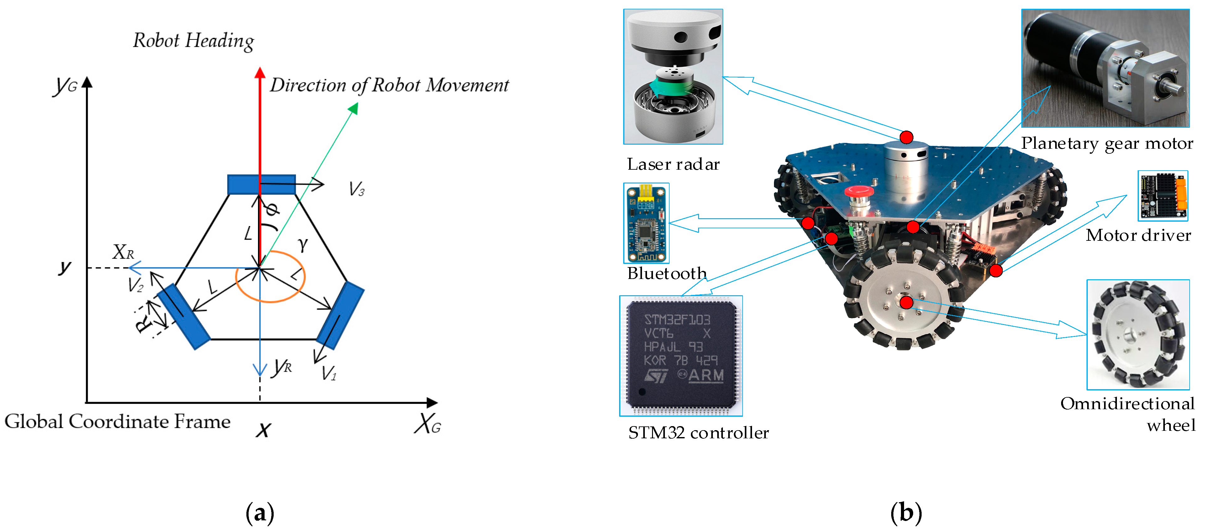
Figure 2.
Energy consumption composition of a Mobile Robot (MR) and signal transmission.
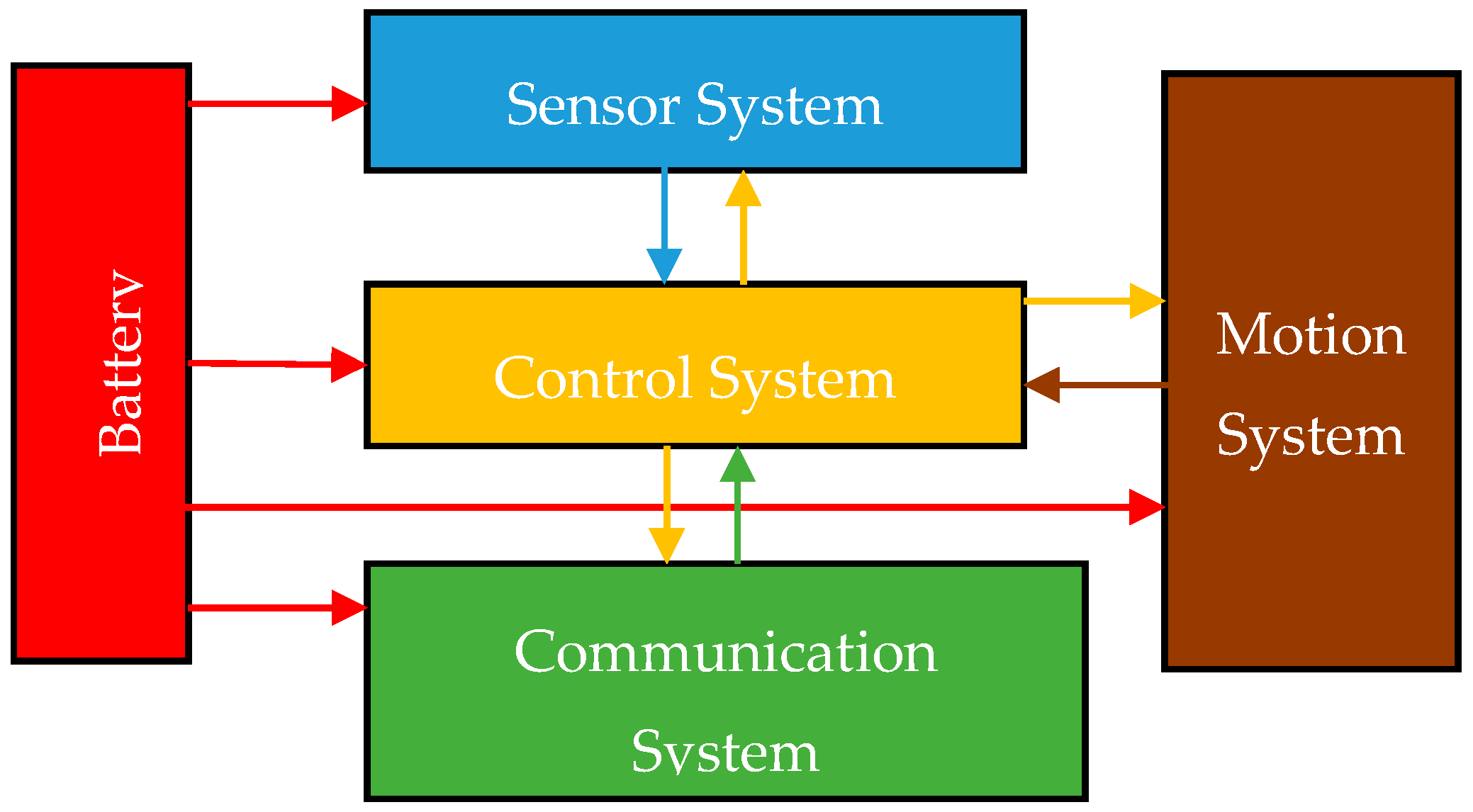
Figure 3.
Diagram of TOMR’s angle analysis.
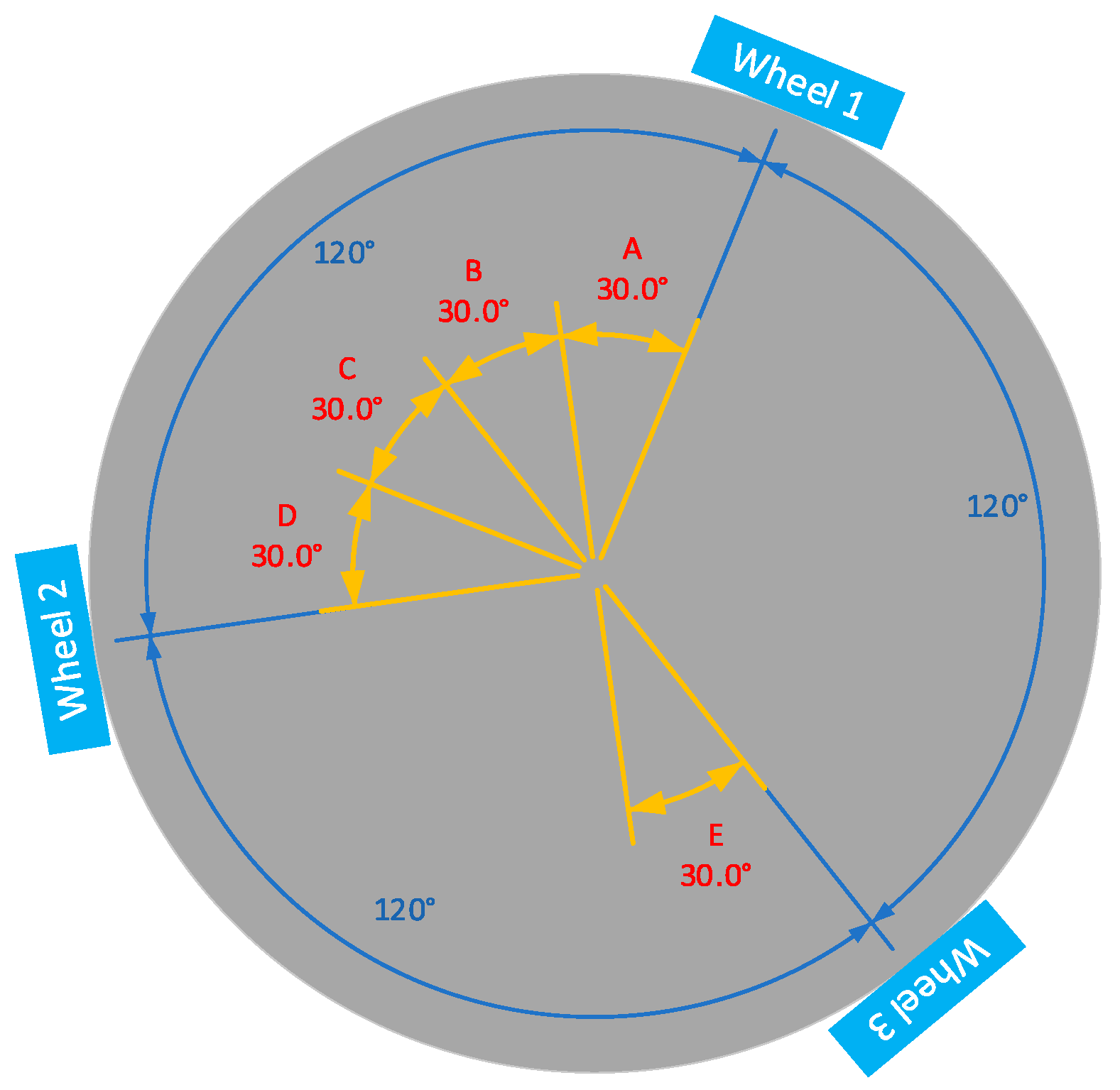
Figure 4.
Speed change versus time.

Figure 5.
Ec, Ef, and Ee change versus time. (a) Ec changes versus time, (b) Ef changes versus time, (c) Ee changes versus time.
Figure 5.
Ec, Ef, and Ee change versus time. (a) Ec changes versus time, (b) Ef changes versus time, (c) Ee changes versus time.
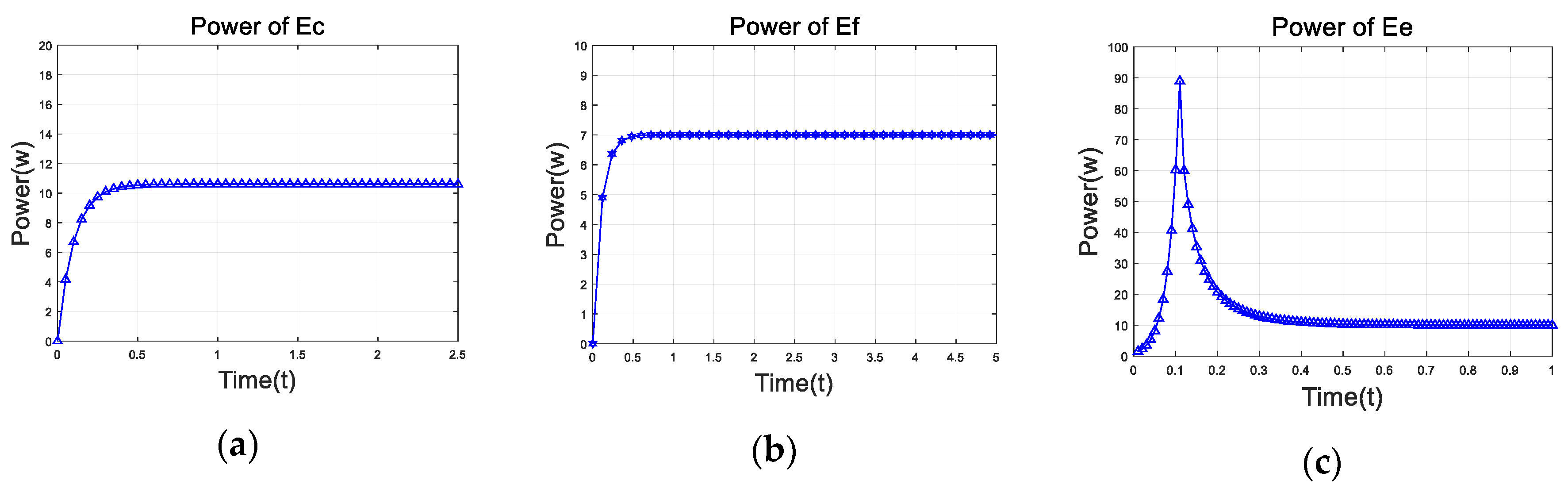
Figure 6.
Ek and Eh change versus time. (a) Ek changes versus time, (b) Eh changes versus time.
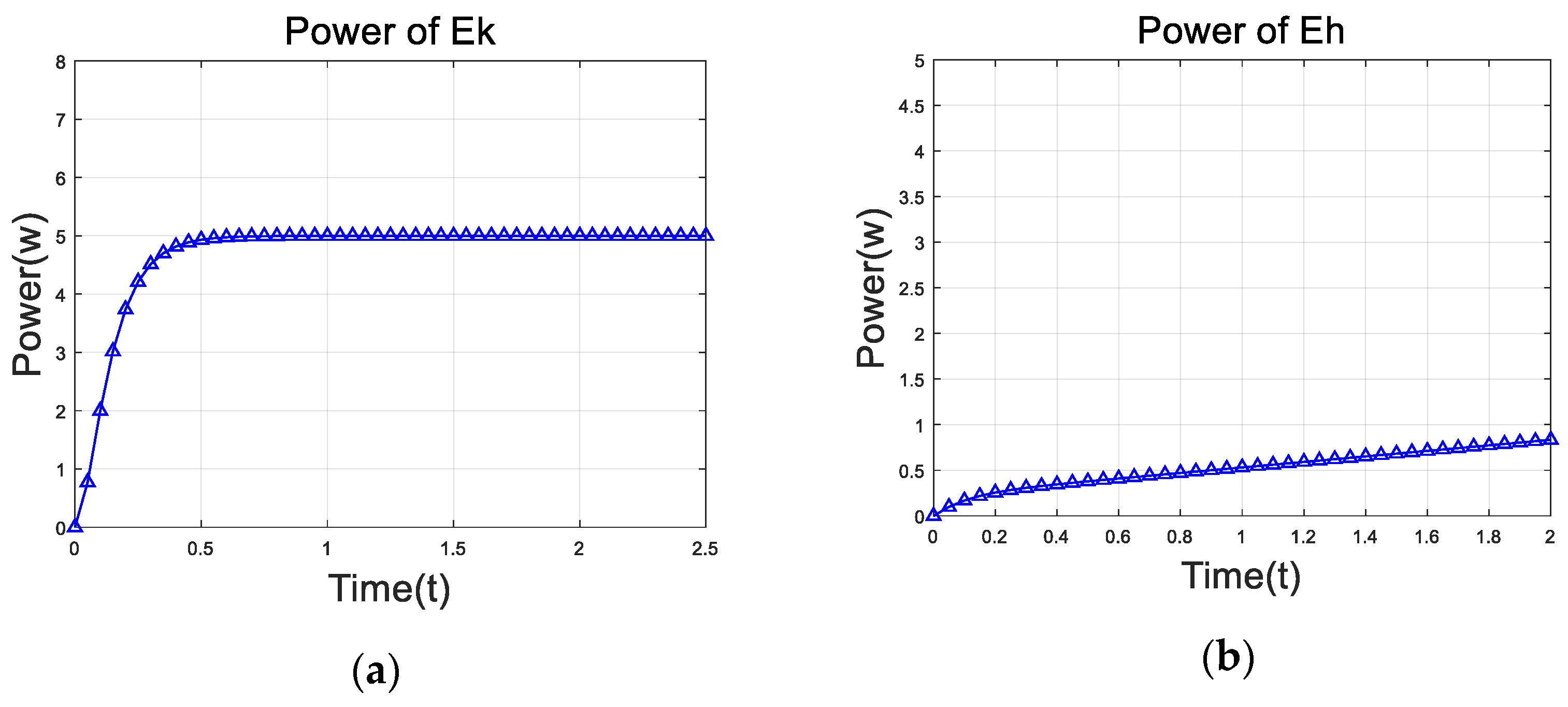
Figure 7.
Power of control system. (a) Start of the process power consumption at an angle of 30 degrees, (b) start of the process power consumption at an angle of 0 degrees, and (c) smooth running power.
Figure 7.
Power of control system. (a) Start of the process power consumption at an angle of 30 degrees, (b) start of the process power consumption at an angle of 0 degrees, and (c) smooth running power.

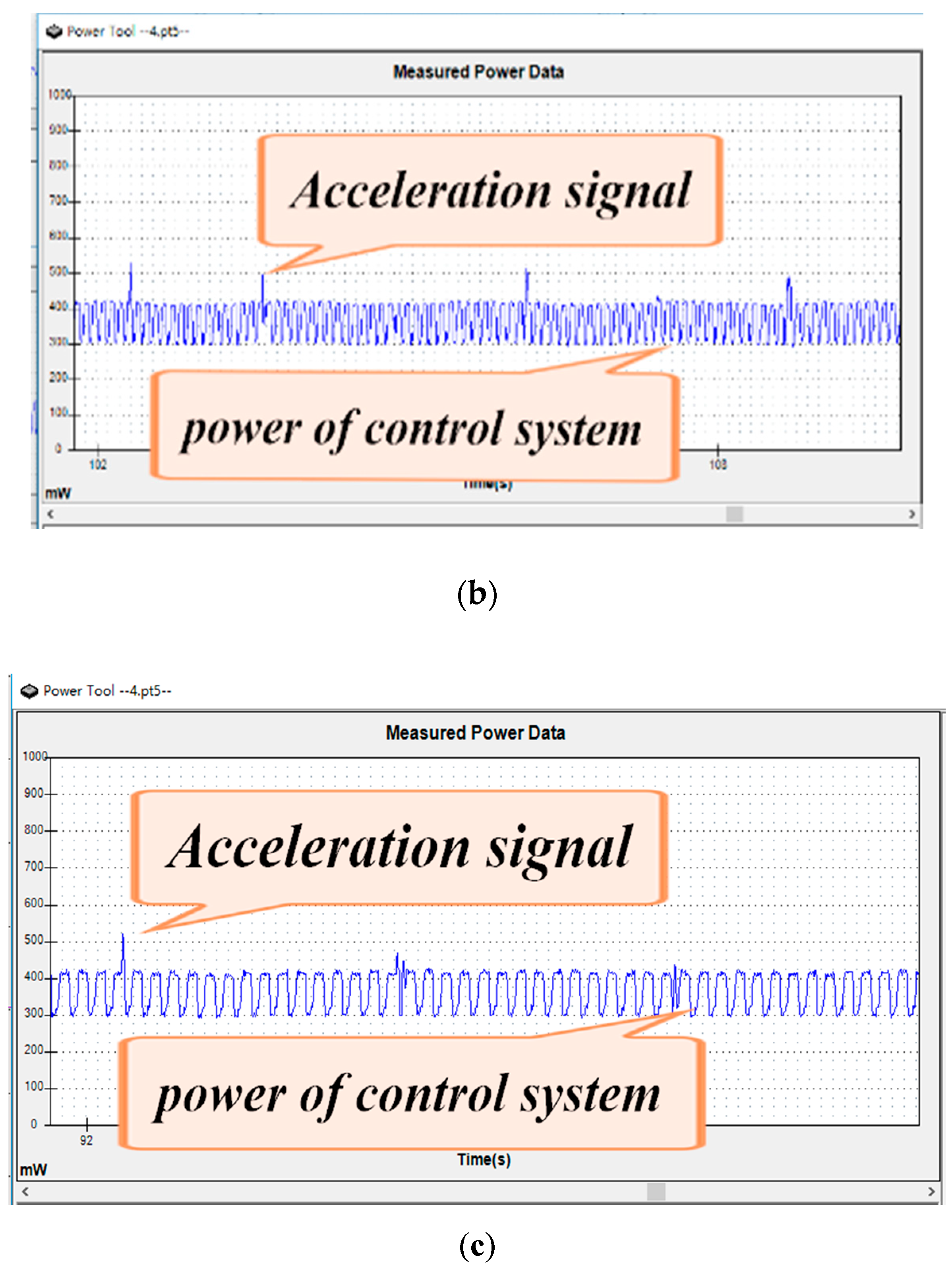
Figure 8.
Power consumption of TOMR moving at different angles.
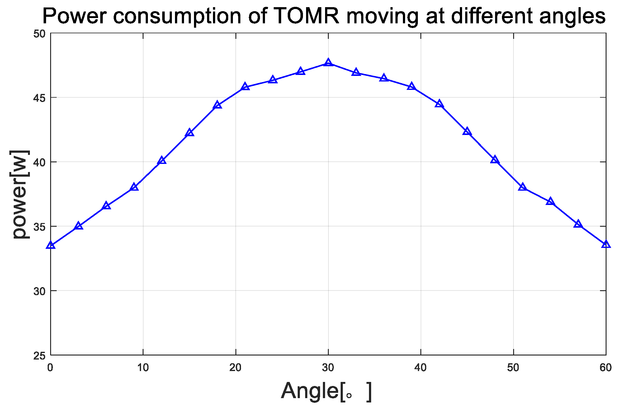
Figure 9.
Power measurement and modeling of TOMR.

Table 1.
TOMR drive wheel parameters.
| Parameter | Motor 1 | Motor 2 | Motor 3 |
|---|---|---|---|
| k10 | 0.0019 | 0.00195 | 0.0020 |
| k20 | 1.2533 | 1.2654 | 1.2589 |
| αR | 1.257 | 1.255 | 1.257 |
| αM | 1.355 | 1.375 | 1.379 |
Table 2.
Motion power comparison between modeling and measurement.
| Time (s) | Robot Speed (m/s) | Modeling Motion System Power (W) | Measurement Motion System Power (W) | Error Percent (%) |
|---|---|---|---|---|
| 0 | 0 | 2.05 | 2.12 | 3.41 |
| 0.05 | 0.329 | 11.462 | 12.062 | 5.23 |
| 0.10 | 0.593 | 47.198 | 49.723 | 5.34 |
| 0.15 | 0.753 | 57.511 | 56.235 | 2.21 |
| 0.20 | 0.850 | 41.321 | 42.210 | 2.15 |
| 0.25 | 0.909 | 36.513 | 35.125 | 3.95 |
| 0.30 | 0.944 | 34.679 | 33.541 | 3.39 |
| 0.35 | 0.966 | 33.474 | 33.548 | 0.02 |
| 0.40 | 0.979 | 33.267 | 34.125 | 2.51 |
| 0.45 | 0.987 | 33.160 | 32.754 | 1.23 |
© 2019 by the authors. Licensee MDPI, Basel, Switzerland. This article is an open access article distributed under the terms and conditions of the Creative Commons Attribution (CC BY) license (http://creativecommons.org/licenses/by/4.0/).
Share and Cite
MDPI and ACS Style
Hou, L.; Zhang, L.; Kim, J. Energy Modeling and Power Measurement for Three-Wheeled Omnidirectional Mobile Robots for Path Planning. Electronics 2019, 8, 843. https://doi.org/10.3390/electronics8080843
AMA Style
Hou L, Zhang L, Kim J. Energy Modeling and Power Measurement for Three-Wheeled Omnidirectional Mobile Robots for Path Planning. Electronics. 2019; 8(8):843. https://doi.org/10.3390/electronics8080843
Chicago/Turabian StyleHou, Linfei, Liang Zhang, and Jongwon Kim. 2019. "Energy Modeling and Power Measurement for Three-Wheeled Omnidirectional Mobile Robots for Path Planning" Electronics 8, no. 8: 843. https://doi.org/10.3390/electronics8080843
Note that from the first issue of 2016, this journal uses article numbers instead of page numbers. See further details here.