


Abstract
The integration of solar energy into smart grids requires high-efficiency power conversion to support grid stability. However, Partial Shading Conditions (PSCs) remain a primary obstacle by inducing multiple local maxima on P–V characteristic curves. This paper presents a hardware-aware and memory-enhanced Maximum Power Point Tracking (MPPT) approach based on a modified Dragonfly Algorithm (DA) for grid-connected microinverter-based photovoltaic (PV) systems. The proposed method utilizes a quasi-switched Boost-Switched Capacitor (qSB-SC) topology, where the DA is specifically tailored by combining Lévy-flight exploration with a dynamic damping factor to suppress steady-state oscillations within the qSB-SC ripple constraints. Coupling the MPPT stage to a seven-level Packed-U-Cell (PUC) microinverter ensures that each PV module operates at its independent Global Maximum Power Point (GMPP). A ZigBee-based Wireless Sensor Network (WSN) facilitates rapid data exchange and supports ‘swarm-memory’ initialization, matching current shading patterns with historical data to seed the population near the most probable GMPP region. This integration reduces the overall response time to 0.026 s. Hardware-in-the-loop experiments validated the approach, attaining a tracking accuracy of 99.32%. Compared to current state-of-the-art benchmarks, the proposed model demonstrated a significant improvement in tracking speed, outperforming the most recent 2025 GWO implementation (0.0603 s) by approximately 56% and conventional metaheuristic variants such as GWO-Beta (0.46 s) by over 94%.These results confirmed that the modified DA-based MPPT substantially enhanced the microinverter efficiency under PSC through cross-layer parameter adaptation.
1. Introduction
Photovoltaic (PV) systems are fundamental to sustainable energy infrastructure owing to their inherent modularity and scalability. However, their energy conversion efficiency is substantially dictated by site-specific environmental conditions [1]. Specifically, partial shading conditions (PSC) induce multiple local maxima on I–V and P–V characteristic curves. These nonlinearities severely limit the GMPP tracking capability of conventional MPPT strategies. As a result of this entrapment, systems often operate at the Local Maximum Power Points (LMPP), leading to significant energy losses and potential hotspot formation. Therefore, high-performance MPPT under PSC has emerged as a critical research priority, focusing on precision, safety, and rapid dynamic responses.
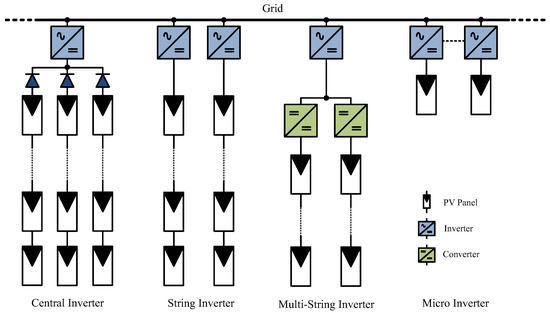
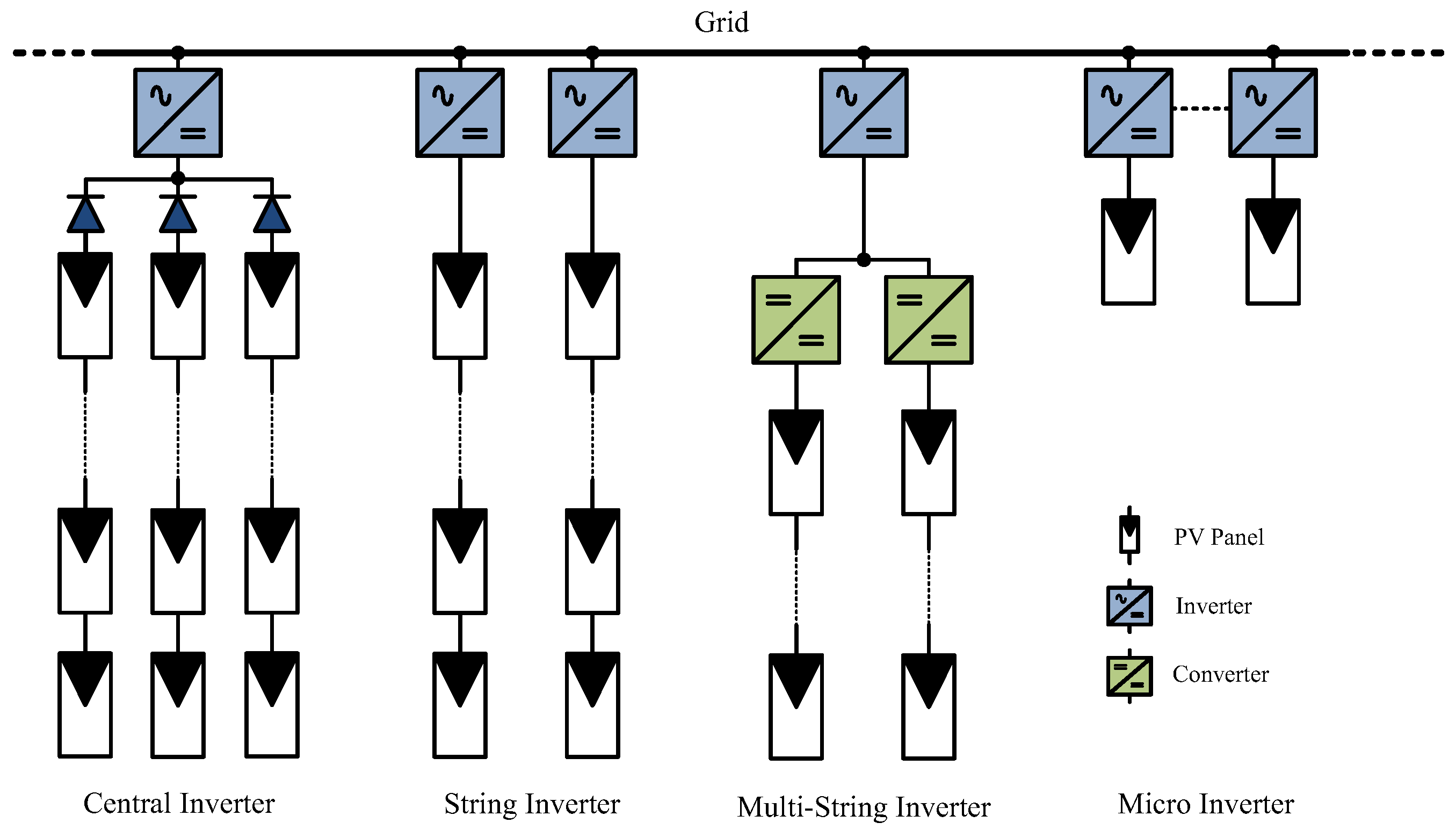
The effectiveness of metaheuristic algorithms has established system-level optimization as a pivotal parameter in mitigating efficiency losses [2]. Simultaneously, microinverter architectures have gained prominence over central and string inverter topologies because of their independent MPPT capabilities and standardized modular compatibility. Whereas centralized and string systems suffer from module mismatch losses, microinverters provide a distributed framework in which each PV module is processed independently. The fundamental transition from centralized to localized power conversion is shown in Figure 1.
Figure 1.
Grid-Connected Inverter Systems.
Despite significant advancements in cell efficiency, with mass-produced monocrystalline cells reaching 23–24% and multi-junction cells up to 47%, environmental factors such as soiling and cloud cover continue to induce cell-level mismatches [3]. These conditions deviate PV arrays from homogeneous operation [2], thereby increasing the complexity of fault diagnosis and long-term maintenance requirements [4]. Previous research demonstrated that localized shading leads to nonlinear I–V characteristics [5], while other studies focused on shading detection via current and voltage measurements at the maximum power point [6]. Additionally, the effects of ripple and active power decoupling on the output performance have been investigated to mitigate energy losses [7,8]. However, conventional strategies such as Perturb and Observe (P&O) and Incremental Conductance (INC) remain inadequate for reliably reaching the GMPP under complex PSC scenarios [9].
The capacity of metaheuristic algorithms to solve nonlinear optimization problems provides substantial opportunities for enhancing MPPT performance. Methods such as Particle Swarm Optimization (PSO), Gray Wolf Optimization (GWO), and Ant Colony Optimization (ACO) have been extensively implemented to improve detection accuracy under PSC [10]. Among these techniques, the DA achieves a robust balance between exploration and exploitation, making it highly effective for navigating multipoint optimization challenges.
This study proposes an integrated MPPT solution featuring a hardware-aware, memory-enhanced modified DA-based qSB-SC structure, a seven-level PUC microinverter, and a ZigBee-based wireless infrastructure. The proposed approach distinguishes itself from standard metaheuristics by integrating Lévy flight trajectories for enhanced global search and a dynamic damping factor to minimize steady-state oscillations. In addition, a cross-layer feedback mechanism is implemented to synchronize the dragonfly step size with the real-time ripple limits of the qSB-SC converter. Simultaneously, the ZigBee-based infrastructure enables ‘Memory-Based Initialization’ by matching current shading patterns with historical data to place the initial population near the probable GMPP region. The technical credibility of the integrated system was validated through comprehensive MATLAB/Simulink version R2023b simulations and real-time laboratory experiments featuring oscilloscope-trace verifications. Ultimately, the resulting synergy ensures highly accurate, rapid (0.026 s), and stable MPPT performance, providing a robust solution for future smart grid and microgrid infrastructure.
The primary contributions of this study are summarized as follows:
Algorithmic Innovation: Development of a modified DA integrated with Lévy flight trajectories to prevent entrapment in local maxima under complex shading.
Hardware-Aware Design: Implementation of a cross-layer feedback mechanism to synchronize MPPT step sizes with the real-time ripple limits of the qSB-SC converter.
Communication Synergy: ZigBee-based ‘Swarm Memory’ strategy that significantly reduces convergence time (0.026 s) by utilizing historical shading data.
Real-time Validation: The proposed system was verified through hardware-in-the-loop (HIL) experiments on an ARM Cortex-M4-based STM32F4 Discovery microcontroller, ensuring high efficiency (99.32%) and low THD (3.36%).
The remainder of this manuscript is organized as follows: Section 2 provides a systematic review of state-of-the-art metaheuristic MPPT methods and microinverter architectures. Section 3 details the proposed system overview, including the PV panel model, innovative DA-based qSB-SC MPPT logic, and the seven-level PUC microinverter topology. Section 4 presents the experimental setup, real-time hardware results on the STM32F4 platform, and comparative performance analysis. Finally, Section 5 concludes the study with a summary of findings and future research directions.
2. Related Works
The optimization of MPPT under PSC has become a focal point in PV research because of the nonlinear characteristics of P–V curves. This section reviews the evolution of metaheuristic algorithms and the advantages of distributed microinverter architectures.
2.1. Metaheuristic Optimization Algorithms for MPPT
The nonlinear characteristics of PV systems under PSCs necessitate robust global maximum power point tracking (GMPPT) strategies to prevent conventional algorithms from being trapped in local maxima. Comprehensive reviews in the literature have systematically categorized metaheuristic optimization techniques, ranging from swarm intelligence to evolutionary algorithms, as highly effective solutions for navigating these nonlinearities [11]. Recent comprehensive reviews and studies published in 2025 have highlighted the increasing prominence of Artificial Intelligence (AI) and nature-inspired optimization in navigating these nonlinearities with high precision [12]. Metaheuristic optimization techniques, inspired by biological behaviors and evolutionary processes, have gained prominence owing to their superior global search capabilities. Furthermore, hybrid strategies that combine traditional P&O with advanced simulation-based characterization have been proposed to enhance tracking reliability under complex shading scenarios [13]. Recent studies published in Electronics have further highlighted that hybridizing these metaheuristics with local search mechanisms can significantly mitigate tracking oscillations and enhance reliability under rapidly changing irradiance [14]. Table 1 provides a systematic comparative evaluation of the state-of-the-art metaheuristic GMPPT methods reported between 2018 and 2025. These techniques, including Grey Wolf Optimization (GWO), DA and innovative hybrids like HMS-RSA FOPID, are analyzed across several critical benchmarks such as algorithmic complexity, tracking convergence time, and efficiency. The synthesized data underscore how modern modifications, ranging from deterministic approaches in Cuckoo Search to multi-objective hybrid frameworks, effectively balance the trade-off between rapid dynamic response and steady-state precision in complex energy-harvesting environments.
Table 1.
Comparison of different GMPPT techniques.
As illustrated in Table 1, although state-of-the-art methods in 2025, such as GWO and HMS-RSA, demonstrate high efficiency, they often require convergence times ranging from 0.05 to 0.45 s. In contrast, the modified DA-based MPPT proposed in this study achieved a significantly faster response time of 0.026 s. This superior dynamic performance is primarily attributed to the ZigBee-based ‘swarm memory’ initialization, which bypasses the need for exhaustive curve scanning during initial power-up or rapid shading transitions. Additionally, the cross-layer adaptation ensures that this speed does not compromise hardware stability, maintaining THD levels as low as 3.36%.
Consistent with these 2025 state-of-the-art developments, a dynamic average-value modelling approach combined with curve-scanning MPPT was recently introduced to maintain stability in specialized PV–battery systems [29]. While such scanning methods offer high reliability for global tracking, a significantly faster convergence time is achieved by the modified DA proposed in this study (0.026 s) by leveraging wireless swarm memory initialization. This approach bypasses the need for periodic full-curve scans, thereby reducing the computational burden on the STM32F4-based hardware platform and enhancing real-time performance.
2.2. Distributed Microinverter Architectures and Grid Integration
Microinverters significantly enhance the flexibility, reliability, and modularity of microgrids by enabling each PV module to independently convert its output power for grid integration. By connecting each PV panel to the grid through its own microinverter, performance issues in a single module, such as shading, panel aging, or localized faults, do not compromise the efficiency of the entire system. This architecture directly optimizes energy production by improving MPPT accuracy across the microgrid. Additionally, because microinverters provide low-voltage AC outputs, they require less DC cabling and offer greater safety than central inverter configurations.
Energy quality remains a critical parameter in modern power systems, directly impacting reliability and sustainability. In this context, microinverter-based PV systems offer significant advantages for power quality improvement using advanced digital control algorithms. The implementation of sophisticated control strategies in grid-connected microinverters is essential to maintain harmonic integrity and voltage stability at the point of common coupling [30]. Notably, microinverters excel at minimizing Total Harmonic Distortion (THD) and actively managing the Power Factor (PF), which represent their core technical strengths [31]. These capabilities ensure precise phase alignment with grid voltage and optimal management of the active–reactive power balance, thereby enhancing overall system performance [32]. In this context, strict adherence to international standards such as IEEE 1547 and IEC 61727 for voltage, frequency, and harmonic limits ensures the reliable integration of microinverters into urban distribution networks and residential settings [33,34,35].
Although these studies demonstrate the potential of metaheuristics, they often lack synchronization with physical converter limits or real-time communication synergy. This gap is addressed by proposing a modified DA that utilizes a wireless infrastructure for memory-based initialization, ensuring superior dynamic response as detailed in the subsequent sections.
3. System Overview
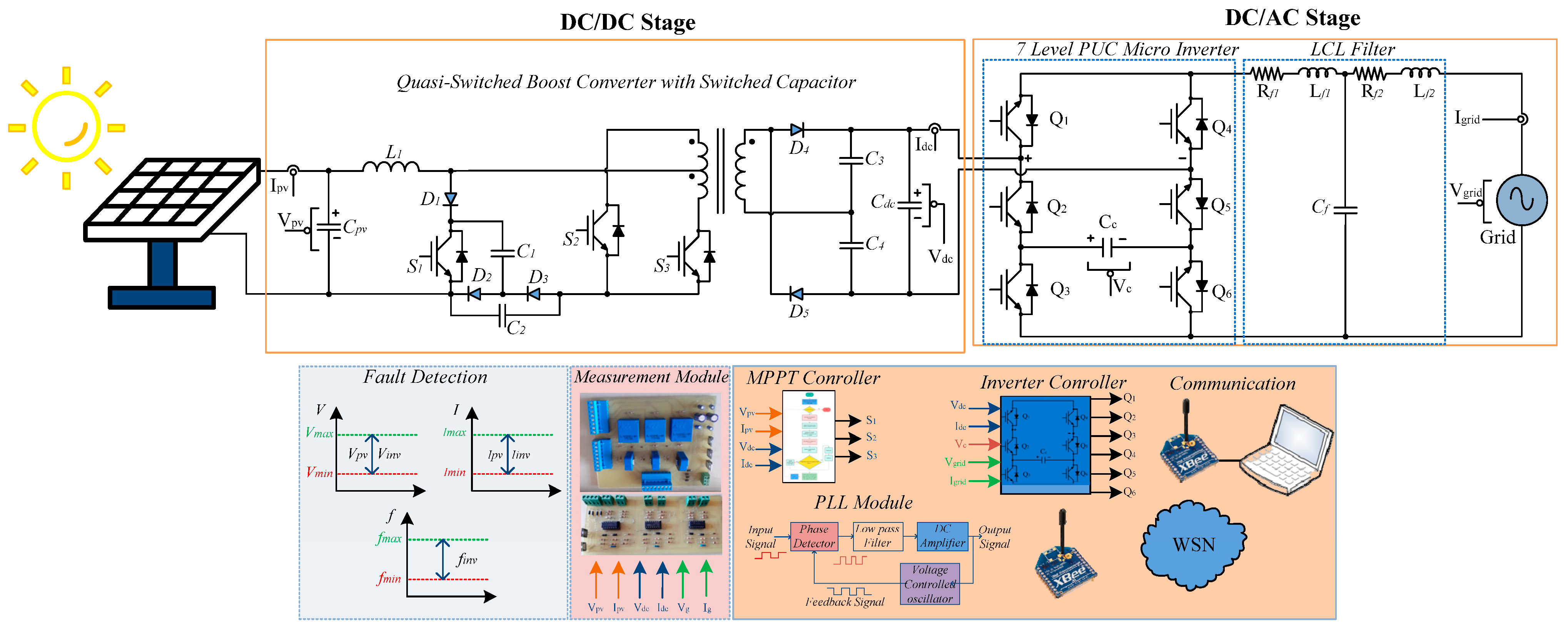
The primary objective of this study was to develop an advanced real-time control and communication framework for microgrids to enhance the stability, flexibility, and efficiency of conventional power grids. This framework facilitates the high-performance integration of renewable energy sources through a modified DA-based qSB-SC MPPT structure coupled with a seven-level PUC inverter topology. Specifically designed for varying irradiance conditions, the integrated energy management and communication system ensures an uninterrupted power supply while enabling active monitoring of production-consumption cycles. By maximizing energy transfer from photovoltaic sources to the grid, the proposed architecture, illustrated in Figure 2, provides a robust solution for decentralized energy management.
Figure 2.
Proposed DA-based qSB-SC MPPT and seven-level PUC Microinverter.
3.1. PV Panel Model
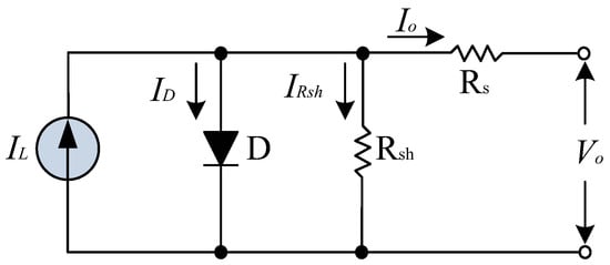
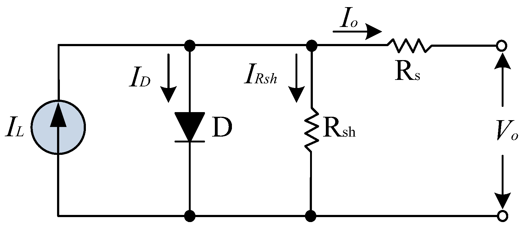
The electrical behavior of a PV cell is characterized by a single-diode equivalent circuit model [32]. This model comprises a light-generated current source IL, diode D, series resistance Rs, and parallel (shunt) resistance Rsh [36]. Specifically, the current source represents the photo-generated current under solar irradiation, whereas the diode models the current–voltage (I-V) relationship of the semiconductor material [37]. The series resistance accounts for internal ohmic losses within the conduction paths and contact points, whereas the shunt resistance represents surface leakage currents [32]. This model is extensively utilized to analytically define the I–V and P–V characteristics and evaluate the system performance under varying environmental conditions, such as irradiance and temperature. A schematic of the single-diode equivalent circuit is shown in Figure 3 [36].
Figure 3.
PV panel equivalent circuit.
The energy obtained from the PV panel depends on the diode ideality factor (ηI), short-circuit current (Isc), and values of the parallel (Rsh) and series (Rs) resistances. Equation (1) provides the equation for obtaining the I–V characteristic curve of the PV panel.
The expressions in Equation (1) represent the light current (IL), series resistance current (IRs), output voltage (Vo), output current (Io), thermal voltage (VT), and ideality factor (ηI).
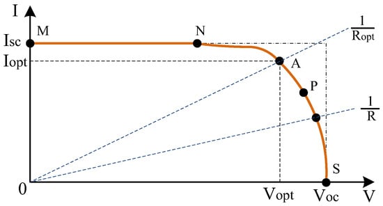
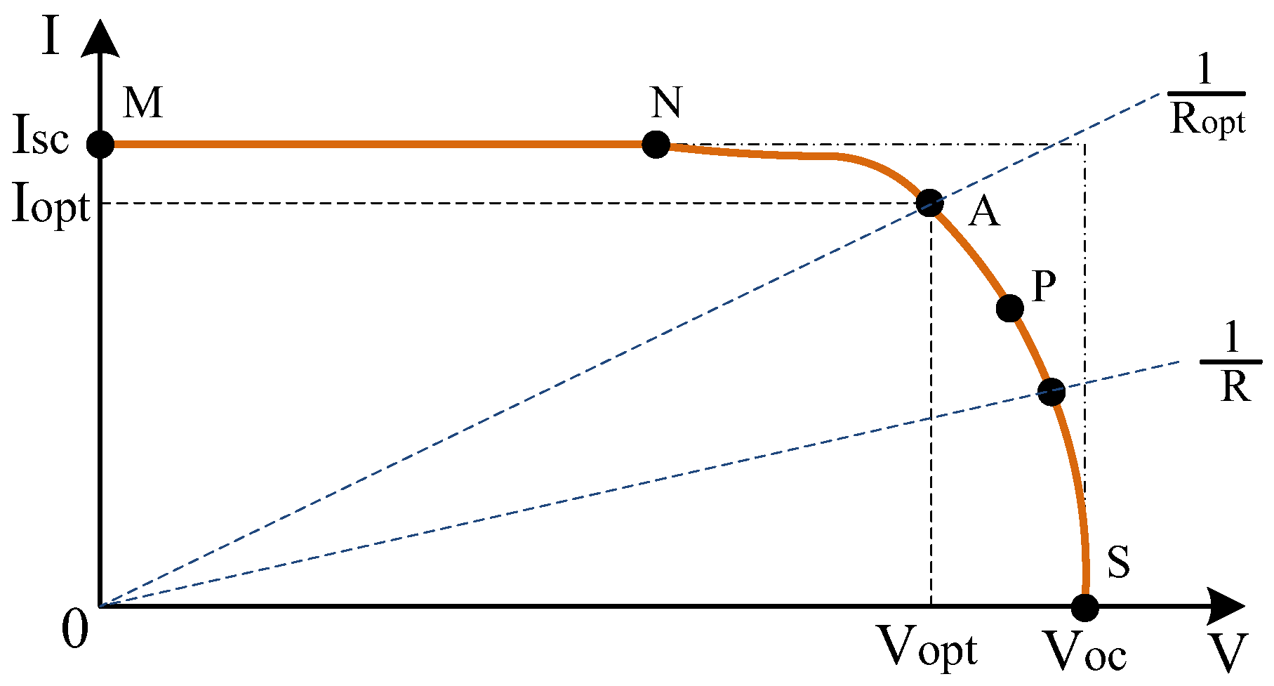
The characteristic curves of PV panels are of critical importance for determining the panel behavior under different load conditions and the Maximum Power Point (MPP) [38]. Figure 4 shows a typical I–V characteristic curve obtained under constant conditions [39,40]. In the case of low load resistance, the panel exhibits behavior similar to that of a current source, and the operating point is located between points M and N, as shown in Figure 4 [41]. In this case, the current drawn from the panel is at a value quite close to the short-circuit current (Isc) [42]. However, when the load resistance is high, the panel exhibits the characteristics of a voltage source [43]. In this situation, the operating point is positioned between points P and S in Figure 4, and the voltage value across the load terminals is close to the panel’s open-circuit voltage (Voc) [41,43]. Accordingly, the PV panel transitions between the behavior of a current source and a voltage source depending on the load resistance [38]. This relationship is one of the fundamental factors affecting the panel output power [44].
Figure 4.
I–V characteristic curve of PV panel at constant temperature and irradiance conditions.
Point A, shown in Figure 4, is the point where the power value that can be transferred from the PV panel to the load is maximum, and it is called the MPP. The value of the load resistance at point A is Ropt, and the slope of the 1/Ropt line is at the optimum point. The output power of the PV panel is expressed as the product of the current and voltage. Equation (2) provides the formula for Pmax, which is the maximum power that can be obtained from the panel.
Equation (3) provides an efficient formula for PV panels. In the equation, G represents the irradiance, and A represents the area of the PV cell. Practically, this equation is calculated using the ratio of the transmitted output power of the panel to the input light power received.
The MPP varies depending on both panel temperature and irradiance level. Therefore, the goal in applications is to make the system operate at the optimum point using MPPT algorithms. The proposed DA-based qSB-SC MPPT method maximizes power transfer by utilizing real-time measurements of I–V curve of the panel.
3.2. DA-Based qSB-SC MPPT
DA is a modern, nature-inspired metaheuristic intelligence optimization algorithm created by studying and mathematically modelling the static and dynamic swarming behaviors of dragonflies found in nature. DA is a powerful and rapid method of solving multidimensional optimization problems. The basis of this algorithm is the imitation of two fundamental instinctive behaviors: seeking food and avoiding enemies [45]. The adaptive adjustment of weight coefficients governing swarm behavior during the optimization process allows the establishment of a balanced relationship between exploration and exploitation [46].
In the designed algorithm, the swarming behavior of dragonflies is defined by five social interaction rules: Separation, Alignment, Cohesion, Attraction, and Distraction. Within these processes, they are represented by six weights to direct the dragonflies to various paths in the problem and search space: separation weight (s), alignment weight (a), cohesion weight (c), food factor (f), enemy factor (e), and inertia weight (w).
Separation: This is used in the algorithm to define the expression for avoiding collisions with neighbors. Equation (4) provides the mathematical equation for the separation action, where X represents the position of the current individual, Xj represents the position of the jth neighbor dragonfly, N represents the number of neighbors of the current individual, and S represents the separation movement of the ith individual [46].
Alignment: This is used in the algorithm to define the expression for the tendency to align with neighbors. Equation (5) provides the mathematical equation for the alignment movement, where Ai represents the alignment movement of the ith individual, N represents the number of neighbors of the current individual, and V represents the velocity of the jth neighbor dragonfly [46].
Cohesion: This is used in the algorithm to define the tendency to move toward the center and proximity of neighbors. Equation (6) provides the mathematical equation for the cohesion movement, where Ci represents the cohesion of the ith individual, N represents the number of neighbors of the current individual, Xj represents the position of the jth neighbor dragonfly, and X represents the position of the current individual [46].
Attraction: This is used in the algorithm to define the dragonfly behavior of approaching the food source. Equation (7) provides the mathematical equation for the attraction movement, where Fi represents the attraction of food—the movement towards the food source—for the ith individual, X+ represents the position of the food source, and X represents the position of the current individual. The food source mentioned here refers to the position of the dragonfly with the best objective function found so far (X+) [46].
Distraction: This is used in the algorithm to define the tendency of dragonflies to escape from or distract enemies. Equation (8) provides the mathematical equation for the distraction movement, where Ei represents the movement of the ith individual away from the enemy (the worst solution), X− represents the position of the enemy, and X represents the position of the individual. The definition of the enemy mentioned here refers to the position of the dragonfly with the worst objective function found so far (X−) [46].
A step vector ΔX and position vector X are used to update the position of the artificial dragonflies in the problem space. The calculation of the step vector is given in Equation (9).
Here, the coefficients s, a, c, f, e, and w represent the separation, alignment, cohesion, food attraction, enemy distraction, and inertia weight factors, respectively. Equation (10) provides the calculation of the position vectors after the step vector calculation is completed.
Algorithmic Innovations and Customization for PV Dynamics
The proposed MPPT approach distinguishes itself from standard DA implementations through three specific algorithmic modifications designed to synchronize with the electrical dynamics of grid-tied microinverters. First, to overcome the stagnation problem in non-convex P–V curves characteristic of complex partial shading, the search mechanism is enhanced by integrating Lévy flight trajectories. This integration allows the algorithm to perform long-distance jumps in the search space, effectively escaping local maxima (LMPPs), and ensuring robust convergence to the GMPP.
Second, unlike generic metaheuristic optimizers that operate independently of the converter’s physical limits, the proposed DA incorporates a Cross-Layer Feedback mechanism. A dynamic damping factor was utilized to adjust the dragonfly step size according to the real-time ripple tolerances of the qSB-SC converter. This hardware-aware strategy ensures that the inductor current (L1) and capacitor voltage (C1 and C2) fluctuations remain within the design constraints (10% and 2.5%, respectively) even during rapid transients.
Finally, the system utilizes a ZigBee-based wireless infrastructure to implement a Memory-Based Initialization strategy. By matching current shading patterns with historical spatial data stored in the central unit—a concept referred to as ‘swarm memory’—the algorithm places the initial population directly near the most probable GMPP region rather than using a random distribution. This synergy between communication and optimization significantly reduces the computational load and shortens the convergence time to as low as 0.026 s, providing a superior dynamic response compared with standard DA- or PSO-based trackers.
As summarized in Table 2, the proposed modifications transform the standard DA into a specialized MPPT controller that prioritizes both tracking speed and hardware safety. This algorithmic differentiation is the primary driver of the 0.026 s response time, which significantly outperforms standard metaheuristic benchmarks, such as PSO and GWO, under identical PSC scenarios.
Table 2.
Technical Comparison between Standard DA and the Proposed Modified DA for MPPT.
The selection of the dragonfly population size (N) was optimized for the hardware environment to balance the tracking speed and computational overhead. Experimental trials indicated that a population of N = 5 provides sufficient exploration diversity for the qSB-SC converter while maintaining the CPU load of the microcontroller within safe operational limits.
The modified DA-based MPPT algorithm was implemented on an ARM Cortex-M4-based STM32F4 Discovery microcontroller (STMicroelectronics, Plan-les-Ouates, Geneva, Switzerland). To handle the computational complexity of Lévy flight trajectories and trigonometric functions within the swarm update rules, the processor’s integrated hardware floating-point unit (FPU) and DSP instructions were utilized. This hardware-level acceleration allows the algorithm to perform high-precision floating-point calculations without taxing the CPU, maintaining a swift execution time for each iteration.
To enable the optimization algorithm to explore the entire decision space with a higher probability, and to increase the ability of artificial dragonfly individuals to move randomly and probabilistically in the search space and strengthen the exploration capacity when neighboring solutions are unavailable, the algorithm exhibits a more balanced global exploration performance by heading toward different regions of the search space without getting trapped in local minima, owing to the Lévy flight approach [46].
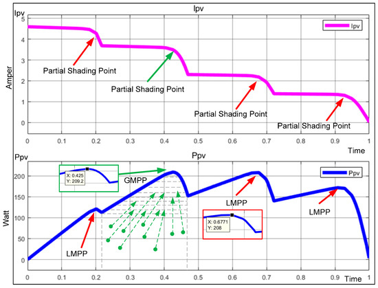
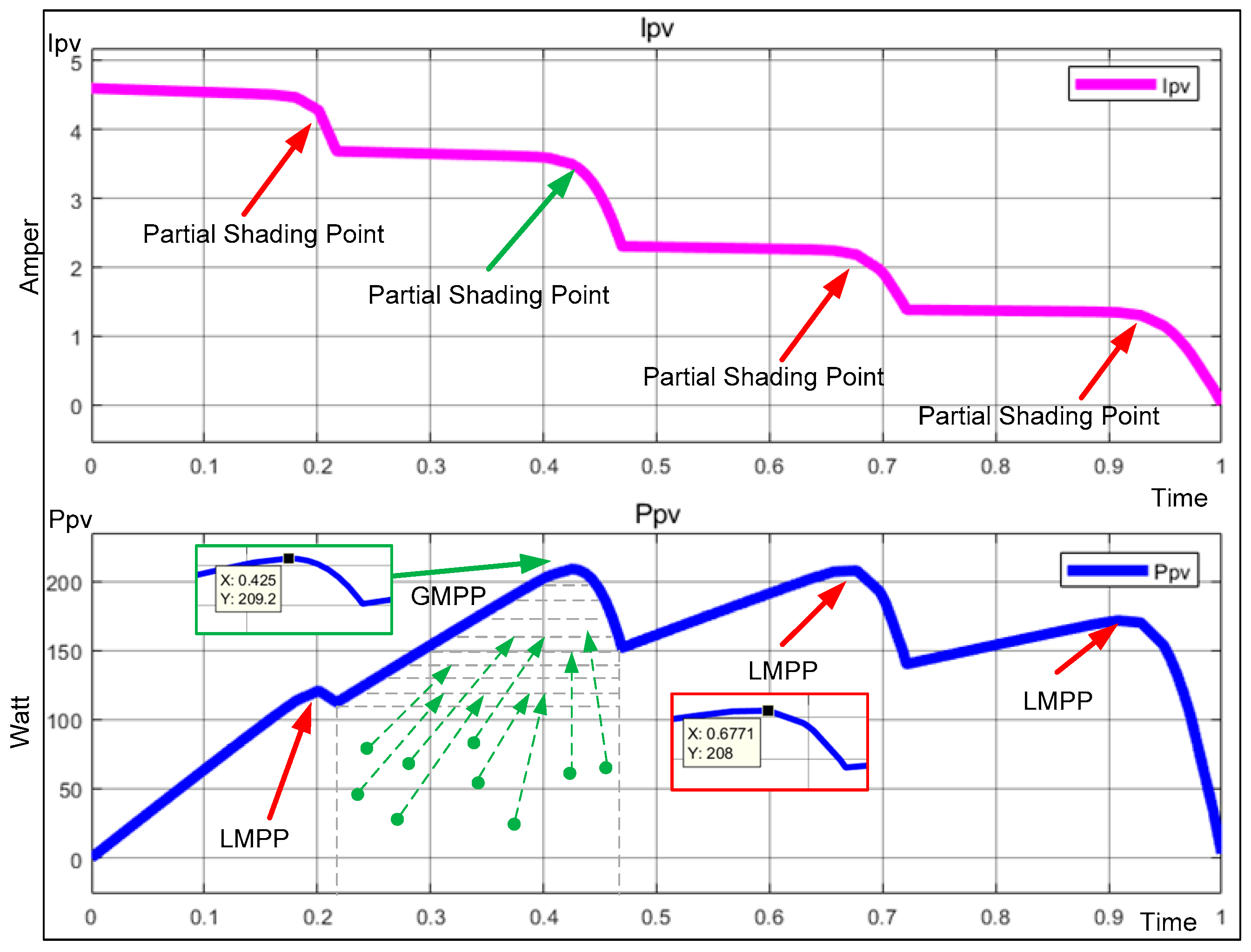
The objective function for the MPPT design is based on maximizing the instantaneous output power of the PV system. Therefore, the goal of the algorithm is to determine the operating point (VMPP, IMPP) at which the maximum electric power (P = V × I) can be obtained from the solar panel. PV systems exhibit nonlinear power-voltage (P–V) characteristics depending on natural environmental conditions such as temperature and solar irradiance. PSC or Complex Partial Shading Conditions (CPSCs) in PV arrays cause the array to have multiple LMPP and a single GMPP. Operating under LMPP conditions instead of GMPP leads to power loss and a decrease in the efficiency of the PV system. Therefore, efficient GMPPT control techniques are required to extract the maximum available power from PV arrays. Figure 5 presents the operation of a PV panel under PSC.
Figure 5.
PV Panel operating under PSCs.
The tracking trajectory illustrated in Figure 5 demonstrates the effective transition of the dragonfly swarm from (represented by green dots) a random initial state to the true GMPP, skipping the surrounding LMPPs through probabilistic jumps (indicated by arrows). As shown in Figure 5, the proposed modified DA avoids the common entrapment issue observed in conventional P&O or standard PSO by executing probabilistic jumps across the power-voltage search space. The tracking cycle demonstrates that the system reaches the true GMPP even when multiple peaks (LMPPs at 120 W, 175 W, and 208 W) are present, ensuring a high energy-harvesting efficiency under complex shading patterns.
Global Maximum Power Point Tracking (GMPPT) is of critical importance for photovoltaic (PV) systems operating under nonuniform conditions [10]. By enabling PV systems to overcome the complex and nonlinear challenges induced by partial shading, GMPPT serves as the fundamental framework that directly determines energy harvesting efficiency and system stability [47]. Consequently, its performance is a key driver of the overall economic sustainability of renewable energy installations [48].
The selection of specific GMPPT algorithms depends heavily on distinct application requirements and system characteristics [47]. Ideally, a tracking method must extract maximum power regardless of weather conditions, ensuring high efficiency and rapid convergence while maintaining a simple implementation and low computational overhead [10]. Recent analyses demonstrate that improved and modified optimization algorithms—particularly hybrid approaches incorporating Artificial Intelligence (AI) techniques—possess the potential to significantly enhance PV performance under PSC compared to conventional methods [47,49].
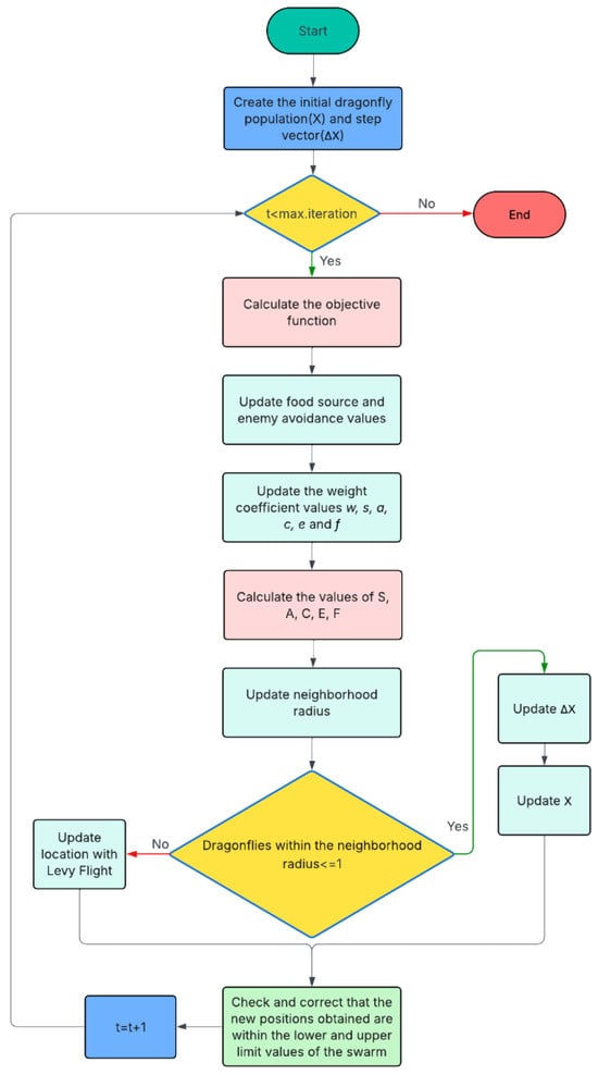
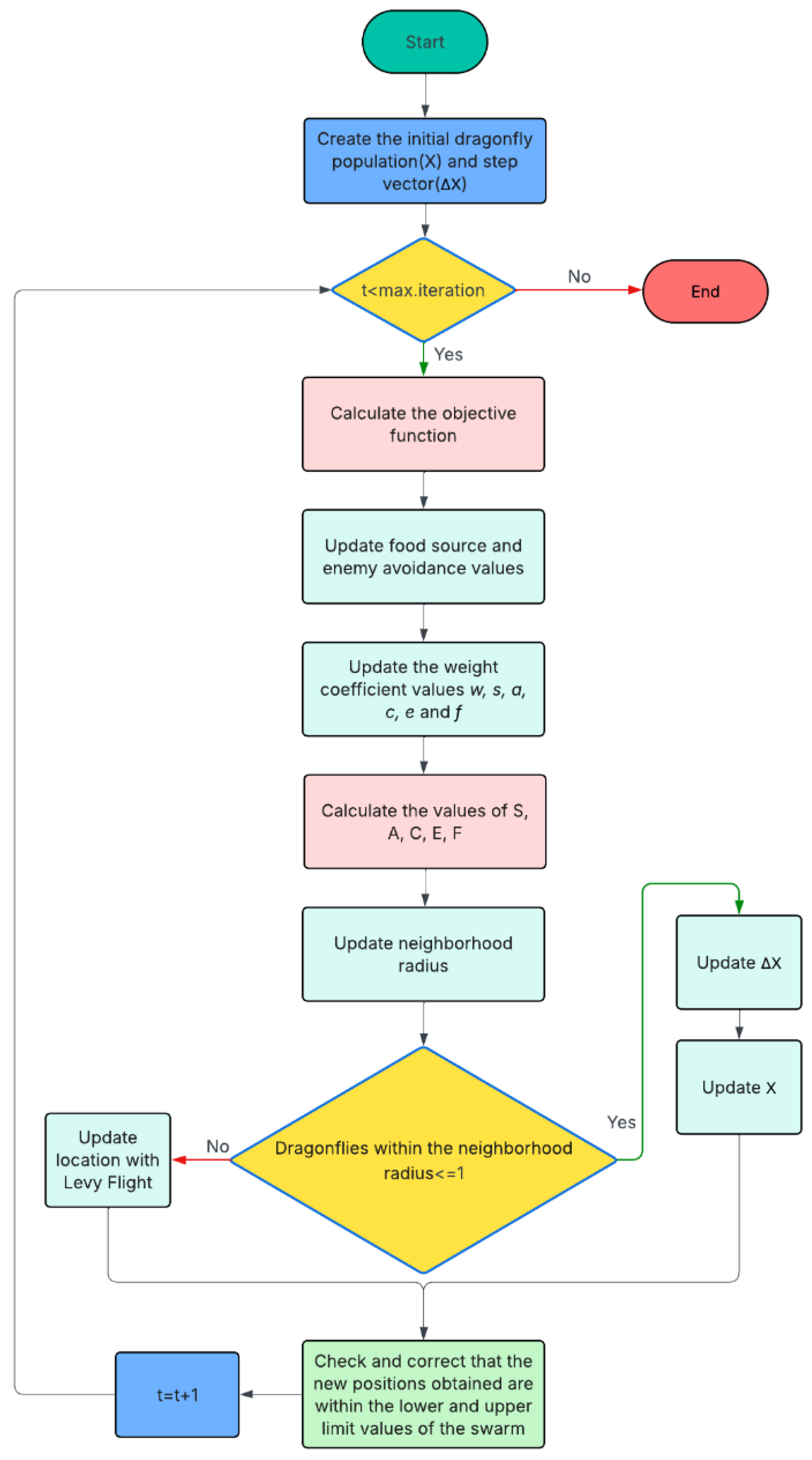
In the DA-based MPPT method proposed in this study, the exploration and exploitation behaviors of dragonfly swarms were modelled, ensuring that each dragonfly represented a candidate operating point of the PV system, and the GMPP was detected with high accuracy. A flowchart of the DA-based MPPT design used in this study is presented in Figure 6.
Figure 6.
Flowchart of the DA-based MPPT.
PV sources used in renewable energy systems inherently produce low-level and variable DC outputs. This situation makes it difficult to directly connect PV panels to the high-voltage DC buses used in grid-connected applications and high-power systems. Consequently, the design and development of DC-DC converters capable of providing high voltage gains and high conversion efficiencies have become primary research areas in modern power electronics. The qSB-SC topologies presented in this study are regarded as prominent solutions in PV systems, hybrid energy sources, and microinverter applications, as they can provide both high-voltage gain and galvanic isolation, where necessary [50,51].
In PV systems, the low-amplitude and variable DC voltage must be boosted for use in grid-connected or high-power applications. For this purpose, isolated high-gain DC–DC converters are the most suitable solution in terms of safety and efficiency.
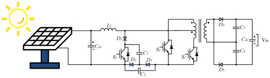
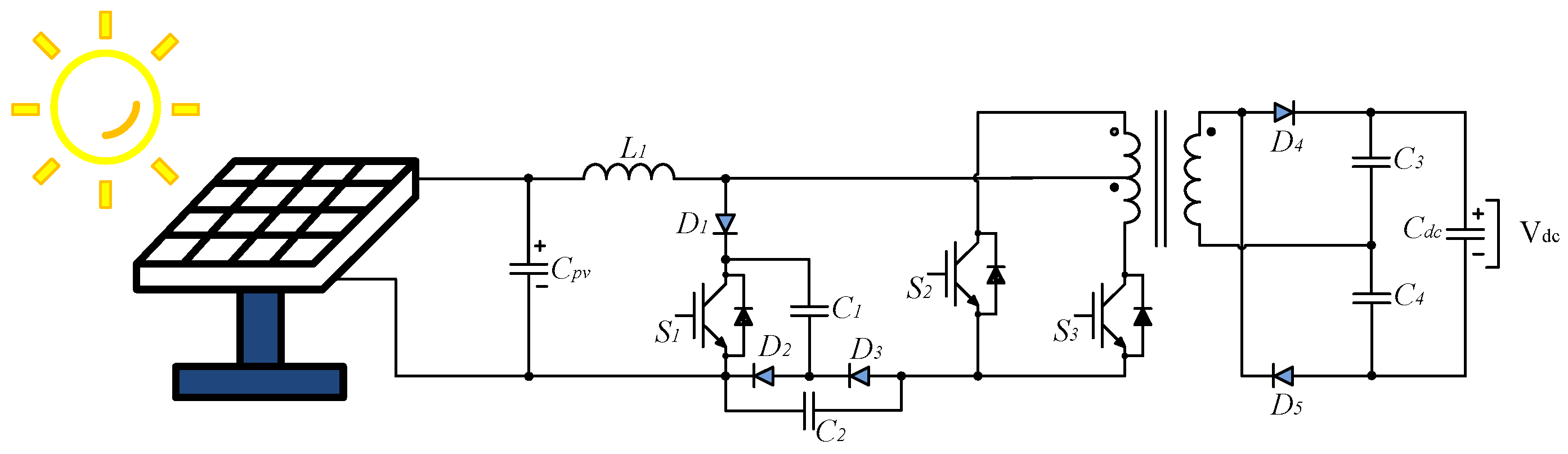
The first power conversion stage of the microinverter system proposed in this study is based on an innovative topology that integrates the qSB network with an SC cell. This structure enables the PV panel to operate at the MPP by converting a low input voltage into a high-amplitude DC bus voltage. The proposed qSB-SC converter scheme is shown in Figure 7.
Figure 7.
Proposed qSB-SC Converter Scheme.
The push–pull network with a high-frequency transformer integrated into the converter not only provides a high voltage gain but also ensures the galvanic isolation of the system. This isolation enhances both user safety and circuit stability and eliminates the risk of saturation by ensuring the balance of the magnetic flux in the converter core.
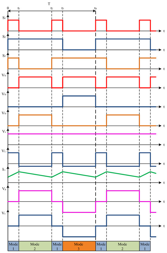
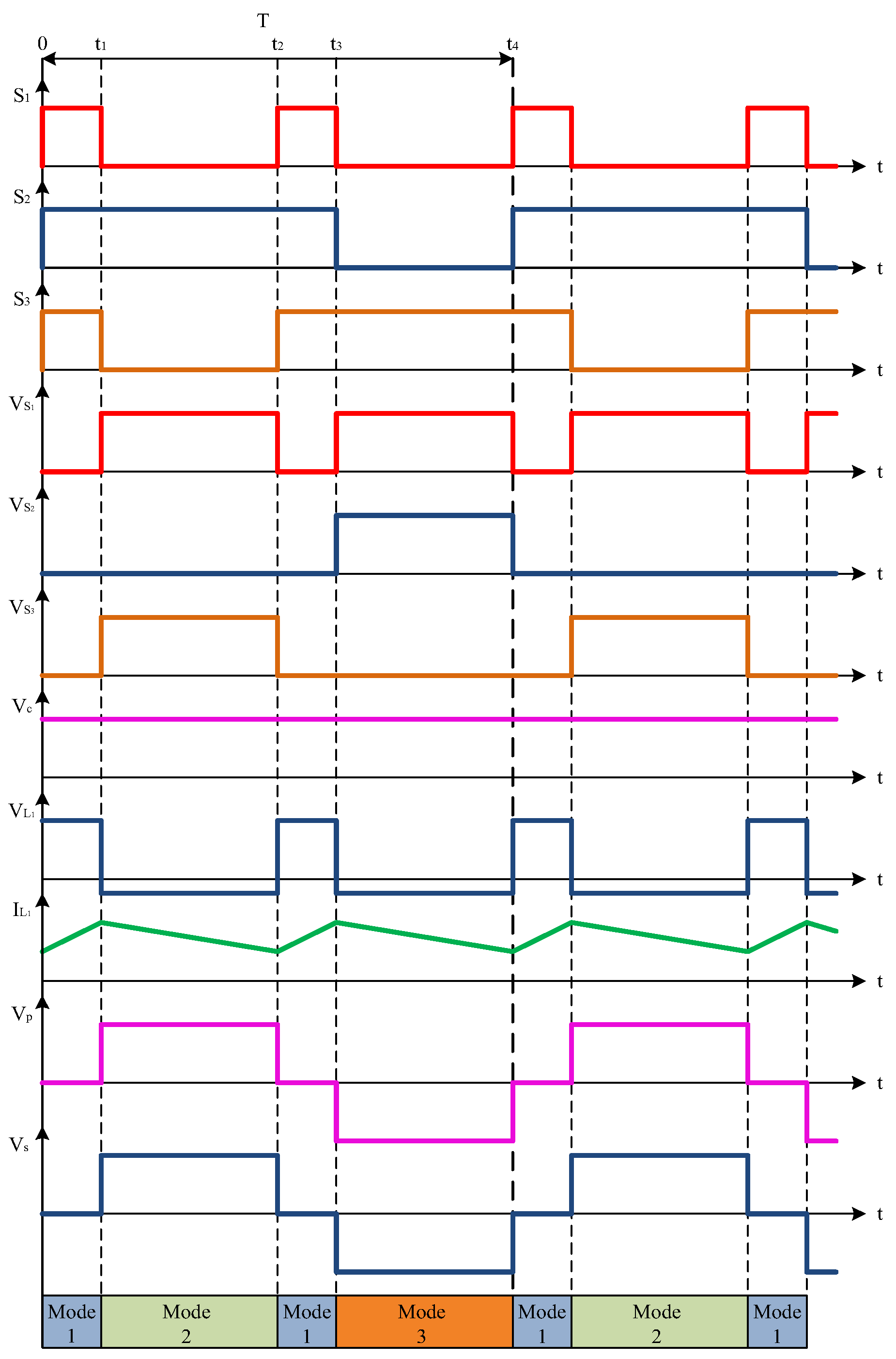
The voltage doubler rectifier (VDR) structure positioned on the secondary side rectifies the alternating voltage at the transformer output, doubling it and obtaining the necessary DC output voltage on the load side. Thus, the system offers advantages such as a low component count, compact circuit structure, high gain, and high conversion efficiency. The proposed qSB–SC-based converter operates in three different operating modes during one switching period. The switching states of the qSB-SC converter are listed in Table 3, and the waveforms are shown in Figure 8.
Table 3.
Switching states of qSB-SC converter.
Figure 8.
qSB-SC waveforms.
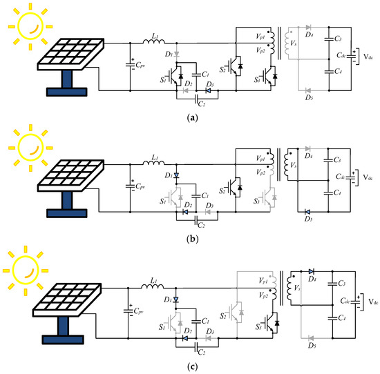
The operating states of the qSB–SC-based DC-DC converter are shown in Figure 8. These modes ensure the achievement of continuous input current characteristics and high-efficiency energy conversion by balancing energy storage and discharge processes. These features indicate that the converter is a suitable solution, particularly for two-stage grid-connected microinverter systems [50,51].
In operating Mode 1, which occurs during the time intervals 0–t1 and t2–t3, the switches S1, S2, and S3 are turned on. They are conducted for a total duration of DT for a period of DT/2 during the 0-t1 interval and for a period of DT/2 during the t2–t3 interval thereby enabling the inductor to store energy. While operating in this mode, the primary circuit of the transformer is short-circuited by switches S2 and S3, and there is no voltage across the secondary circuit. The Vdc value is the sum of the voltages of VC3 and VC4. On the primary side, diodes D1 and D2 are in the cutoff (off state), and only diode D3 conducts (on state). When capacitor C1 discharges through diode D3, the sum of Vpv and VC2 voltages is induced across inductor L1. The Mode 1 operating state is shown in Figure 9a, and the primary-side equivalent circuit is shown in Figure 10a.
Figure 9.
Operation of qSB-SC high boost voltage converter (a) Mode I. (b) Mode II. (c) Mode III.
Figure 10.
Transformer primary side equivalent circuits (a) Mode I. (b) Mode II. (c) Mode III.
In operating Mode 2, which occurs during the time interval t1–t2, only switch S2 is activated. Diodes D1, D2, and D5 are conducting, where diodes D3 and D4 are in the cutoff. During the period in which diodes D1 and D2 conduct for a duration of (T/2) × (1-D), the energy stored across the inductor while operating in Mode 1 is transferred to the load through the transformer and capacitors. The Mode 2 operating state is shown in Figure 9b, and the primary-side equivalent circuit is shown in Figure 10b.
In operating Mode 3, which occurs during the time interval t3–t4, only switch S3 is conducting. Switches S1 and S2 are in cutoff for a duration of (T/2) × (1-D). Diodes D1, D2 and D4 are conducting (on), while diodes D3 and D5 are in cutoff. The energy stored in the inductor while operating in Mode 1 is transferred to the load through the transformer and capacitors. The Mode 3 operating state is shown in Figure 9c, and the primary-side equivalent circuit is shown in Figure 10c.
Equation (11) provides the value of inductor voltage VL1 in operating in Mode 1. VC is the voltage across capacitors C1 and C2.
Equation (12) provides the value of inductor voltage VL1 in operating Mode 2 and Mode 3. VC is the voltage across capacitors C1 and C2.
The converter’s operating period is divided into two main intervals, depending on the duty cycle (D); DT during Mode 1 and (1-D), T during Mode 2 and 3. To ensure steady-state operation in continuous conduction mode (CCM), the average of the inductor voltage over one switching period (T) must be zero. Equation (13) shows this equation.
Equation (14) provides the rearrangement of the equation based on the operating periods of Mode 1, Mode 2, and Mode 3.
Equation (15) is obtained by substituting the VL1 voltage values for Mode 1, Mode 2, and Mode 3 into the equation given in Equation (14). The rearranged form of the equation is presented in Equations (16)–(18).
Equation (19) provides the value of VC. This equation defines the voltage across the capacitors as a function of the Vpv voltage and the duty cycle (D) of the operating period. This expression is critically important for steady-state operation. Provided that the duty cycle D < 0.5, the final voltage gain of the converter can be calculated using this equation.
Equation (20) provides the voltage equation for the primary side of the transformer in operating Mode 2 and Mode 3.
Equation (21) provides the equation for the secondary voltage Vs of the transformer, which has a conversion ratio of N.
Equation (22) provides the equation for the Vdc voltage obtained from the secondary side. The Vs voltage is doubled at the output by the voltage doubler circuit.
Stable energy transfer is ensured by using the energy stored across the inductor during Mode 2 and Mode 3 operating states. Equation (23) provides the voltage gain (G) formula for the implemented qSB-SC converter.
In the equation given in Equation (23), N represents the conversion ratio of the transformer, and D represents the duty cycle of the switch used in the relevant mode. The qSB-SC converter can provide high gain even at low switching ratios [50].
3.3. Passive Component Selection and Design Criteria
The volumetric compactness and manufacturing cost of the converter topology directly depend on the values and physical sizes of the passive energy storage components (inductors and capacitors) used in the circuit. During the selection of passive components, the converter’s electrical performance, cost, circuit dimensions, and volumetric constraints are evaluated. Ensuring that the system’s fundamental quality parameters, current and voltage ripples, remain within the predetermined design tolerances is achieved through the precise calculation of inductor and capacitor values.
Equation (24) provides the fundamental relationship between inductor voltage and inductor current.
Equation (25) provides the fundamental calculation for the inductor current ripple ratio. Equation (26) is obtained by substituting the VC value into this equation. The inductor current ripple ratio presented in Equation (27) is obtained by performing the operations given in Equation (26).
The precise calculation of the inductor value is crucial for ensuring operation in CCM and preventing the inductor current ripple () from exceeding the maximum permissible level. Additionally, keeping the inductor current ripple ratio within certain limits is also important for minimizing magnetic core losses and electromagnetic interference (EMI).
The capacitor voltage ripple () is calculated using the fundamental current-voltage relationship within one switching period. Equation (28) provides the basic current-voltage equation for a capacitor.
Equation (29) provides the equation for the voltage ripple () of capacitors C1 and C2 located on the primary side of the transformer. The Cp value is equal to the value of capacitors C1 and C2.
Equation (30) provides the equation for the voltage ripple () of capacitors C3 and C4 located on the secondary side of the transformer. The Cs value is equal to the value of capacitors C3 and C4. The parameters used and calculated in the design are given in Table 4.
Table 4.
Calculated and Used Parameters.
3.4. DA-Based qSB-SC MPPT Performance Analysis
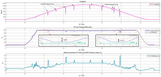
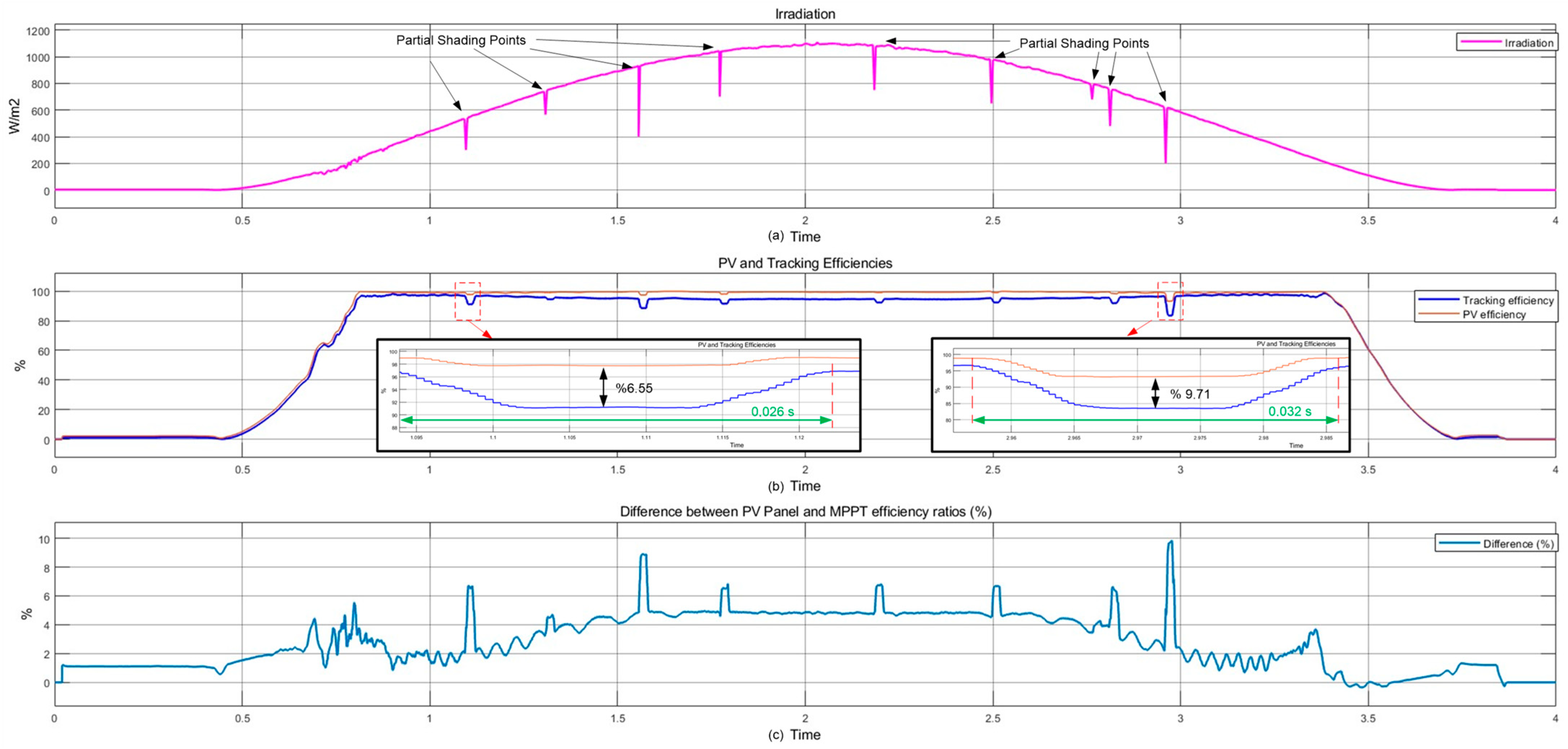
The performance analysis of the designed DA-based qSB-SC MPPT approach is of critical importance for determining how effectively and quickly the algorithm can harvest energy from the PV panel. This section of the study will perform dynamic performance analysis, stability analysis, and efficiency analysis of the designed DA-based qSB-SC MPPT approach. The operating conditions and performance analysis of the DA-based qSB-SC MPPT under PSC are presented in Figure 11. The irradiance variation curve observed during the day and the drops that may occur due to partial shading at nine randomly selected points according to the scenario are presented in Figure 11a. The tracking efficiency of the DA-based qSB-SC MPPT design and the efficiency calculated based on the available irradiance, derived from the PV panel’s production graph, are presented in Figure 11b. The percentage difference between PV panel efficiency (according to catalog values) and MPPT efficiency is presented in Figure 11c. The efficiency and tracking time values of the MPPT system according to the shading scenarios are given in Table 5.
Figure 11.
Performance Analysis of DA-Based qSB-SC MPPT: (a) Irradiation, (b) PV and Tracking Efficiencies, (c) Difference between PV Panel and MPPT efficiency ratios.
Table 5.
MPPT System Efficiency and Tracking Time Performance Under Various Partial Shading Scenarios.
The analysis of the algorithm first involved examining the response time required to reach the MPP during sudden changes in irradiance level. The DA-based qSB-SC MPPT operating under nine different PSCs reaches the MPP fastest in 0.026 s and slowest in 0.032 s.
In the 4th scenario, where the fastest response and tracking time was obtained, the irradiance level decreased from 1042 W/m2 to 700 W/m2, representing a 32.82% reduction. Despite a 342 W/m2 drop in irradiance, a maximum difference of 6.55% occurred between the PV panel factory production efficiency values and DA-based qSB-SC MPPT efficiency values of partial shading. The algorithm quickly tolerated the 6.55% efficiency difference between 1.772 and 1.798 s, closely approaching the factory production data.
In the 9th scenario, where the slowest response time was obtained, the irradiance level decreased from 625 W/m2 to 200 W/m2, representing a 68% reduction. Despite a 425 W/m2 drop in irradiance, a maximum difference of 9.71% occurred between the PV panel factory production efficiency values and DA-based qSB-SC MPPT efficiency values under PSCs. The algorithm quickly tolerated the 9.71% efficiency difference between 2.956 and 2.988 s, closely approaching the factory production data.
In the 1st scenario, the irradiance level decreased from 534 W/m2 to 300 W/m2, representing a 43.82% reduction. A maximum efficiency difference of 6.56% was observed between the PV panel ideal efficiency values and the DA-based qSB-SC MPPT efficiency values under PSCs. The algorithm quickly tolerated this efficiency difference, closely approaching the factory production data within a tracking time of 0.029 s during the 1.093–1.122 s interval.
In the 2nd scenario, the irradiance level decreased from 739 W/m2 to 567 W/m2, representing a 23.27% reduction. The maximum efficiency difference in this scenario was 3.81%, one of the lowest values recorded. The algorithm rapidly closed this difference with a tracking time of 0.028 s during the 1.305–1.333 s interval.
The 3rd scenario involves the second largest irradiance reduction (57.04%) and the second largest efficiency difference (8.88%), with the irradiance level dropping from 931 W/m2 to 400 W/m2. Despite this, the algorithm successfully tolerated the efficiency difference, approaching the ideal efficiency with a rapid response time of 0.027 s during the 1.556–1.583 s interval.
In the 5th scenario, the irradiance level decreased from 1090 W/m2 to 750 W/m2 representing a 31.19% reduction. The maximum efficiency difference was determined to be 6.73%. The algorithm quickly closed this efficiency difference with a tracking time of 0.029 s during the 2.183–2.212 s interval.
In the 6th scenario, the irradiance level decreased from 983 W/m2 to 650 W/m2, representing a 33.88% reduction. The efficiency difference recorded was 6.67%. The algorithm tolerated this difference, reaching a stable operating point with a tracking time of 0.028 s during the 2.495–2.523 s interval.
The 7th scenario is one of the scenarios where the fastest tracking time was achieved (0.026 s). The irradiance level decreased from 791 W/m2 to 680 W/m2, a relatively low reduction of 14.03%. This scenario, with a low efficiency difference of 4.12%, demonstrates the algorithm’s high speed and accuracy. The algorithm approached the ideal efficiency during the 2.765–2.791 s interval.
In the 8th scenario, the irradiance level decreased from 761 W/m2 to 480 W/m2, representing a 36.93% reduction. The maximum efficiency difference was recorded as 6.65%. The algorithm tolerated the difference, approaching the ideal efficiency with a tracking time of 0.031 s during the 2.808–2.839 s interval.
The obtained results clearly demonstrate that the DA-based qSB-SC MPPT operates in continuous mode and maintains a highly stable operating point near the MPP. Crucially, the algorithm exhibits exceptional dynamic stability during transient conditions, effectively mitigating random or uncontrolled power oscillations (ripple), which is a key requirement for robust control in PV systems.
To evaluate the performance of the proposed modified DA-based MPPT, a systematic comparison was conducted against standard benchmark algorithms, including P&O, PSO, and GWO, under identical shading profiles as defined in Table 5. While conventional P&O exhibits high efficiency only under single-peak conditions, it frequently fails to locate the GMPP under PSC, often oscillating around local maxima. In contrast, metaheuristic benchmarks like PSO and GWO demonstrate global search capabilities but suffer from higher convergence times (ranging from 0.06 s to 1.2 s) and significant steady-state ripples. The proposed hardware-aware DA utilizes the Lévy flight mechanism to skip local entrapments and achieves a stable GMPP in as little as 0.026 s, outperforming these benchmarks in both dynamic response and steady-state precision.
To conclude the performance analysis of the proposed MPPT logic, a comprehensive benchmark was conducted against traditional and metaheuristic methods. As summarized in Table 6, the modified DA-based approach is more successful in terms of monitoring speed and accuracy. Following this algorithmic validation, the subsequent section details the seven-level PUC microinverter structure, which is responsible for converting the harvested maximum power into high-quality AC power for grid integration.
Table 6.
Comparative Performance Analysis of MPPT Algorithms under Identical Shading Scenarios.
3.5. Seven-Level PUC Microinverter Design
The power conversion architecture in PV energy systems is one of the most critical elements determining the system’s overall efficiency, reliability, and cost-effectiveness. Conventional central inverter and string inverter topologies have been preferred for many years in large-scale PV installations. However, these structures can lead to significant energy losses in cases of mismatch among modules and partial shading. For this reason, microinverter-based systems have rapidly gained prominence in recent years, especially in rooftop and distributed PV applications.
Microinverters consist of an independent MPPT, DC–DC converter and DC–AC inverter unit directly integrated into each PV module. This structure achieves module-level maximum power tracking, eliminating power imbalances caused by environmental and physical factors such as shading, soiling, dust accumulation, spectral changes, temperature differences, or manufacturing tolerances. Consequently, the system ensures optimum energy conversion on a module basis and achieves high system efficiency in terms of total output power. Moreover, microinverters offer a user-friendly solution with advantages like plug-and-play capability, modular expansion options, and low maintenance requirements.
In the central inverter system, PV panels are connected in series and parallel arrays to provide the required current and voltage values, and all energy conversion is performed by a single high-capacity inverter. Although this topology is economical for large systems, shading or a fault occurring in any single panel negatively impacts the performance of the entire array. In a string inverter topology, enough PV panels are connected in series to establish a specific voltage level, and the energy conversion for each series string is provided by an independent string inverter. However, mismatches between the strings can still limit total efficiency. Conversely, the microinverter architecture enables each PV panel to operate independently, offering a significant performance advantage over string-based systems [52].
Having its own MPPT and DC–AC conversion structure significantly increases the system’s resilience to shading, soiling, and temperature variations. It also offers technical advantages such as higher modularity, enhanced safety due to low DC voltage lines, and improved anti-islanding performance for multi-unit operations [53]. Advanced microinverter topologies, such as quasi-single-stage resonant architectures, further enhance this performance through sophisticated control strategies [54]. Therefore, microinverter systems—especially when integrated with WSNs for enhanced monitoring—stand as high-performance, scalable, and safe solutions for both residential rooftop applications and modular commercial systems [55].
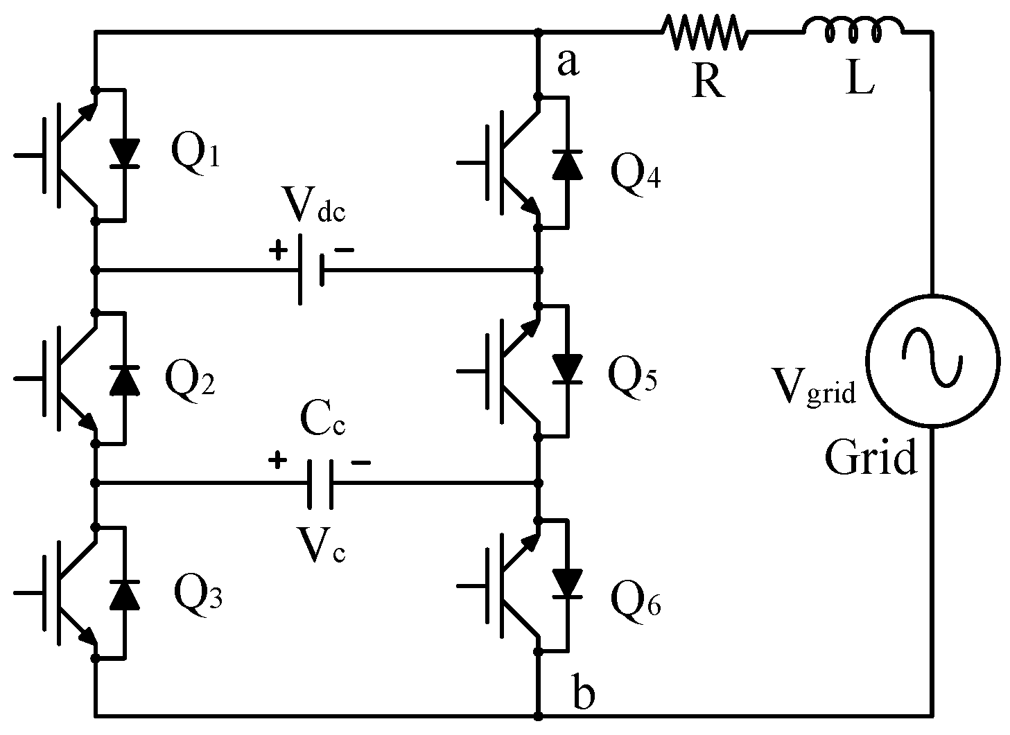
Seven-level PUC inverters stand out as a remarkable solution among modern multilevel inverter topologies, offering promising potential for the high-quality integration of renewable energy sources into the electricity grid. This innovative topology synergistically combines the structural advantages of flying capacitors and cascaded H-bridge inverters, optimizing the complexity and component count of the topology.
The PUC architecture utilizes a significantly reduced number of power electronic switching components compared to conventional multilevel inverters. This optimization is fundamentally achieved through a single isolated DC source and an auxiliary DC-link capacitor that provides balancing between the voltage levels. As direct consequences of this optimization, the system can operate with low switching frequencies, resulting in low THD levels.
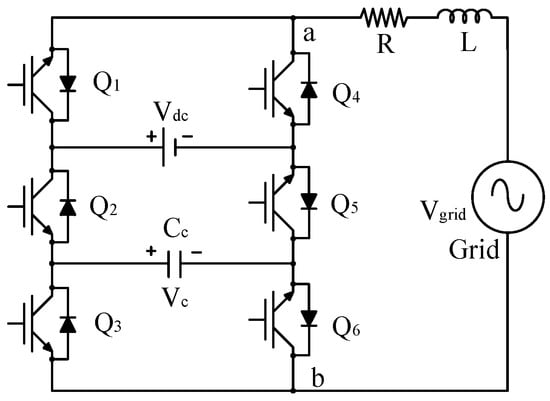
This low harmonic content leads to noticeably less EMI compared to conventional inverter designs, lower voltage stress on power semiconductors, and high-resolution voltage steps in the output waveform. Supported by superior control strategies, seven-level PUC inverters scientifically prove the topology’s superior performance and reliability by exhibiting a fast and accurate dynamic response even under dynamic load changes, DC source voltage fluctuations, and variable power factors. The detailed power electronics schematic of the seven-level PUC microinverter used in this study is presented in Figure 12.
Figure 12.
Seven-level PUC Microinverter.
The switching states of Q1, Q2, Q3, Q4, Q5 and Q6 are provided in Table 7. Switches Q4, Q5 and Q6 are the inverse of switches Q1, Q2 and Q3, respectively. The equation detailing the operating state of each switch is given in Equation (31).
Table 7.
Switching States of Seven-level PUC Microinverter.
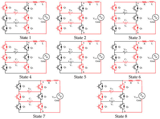
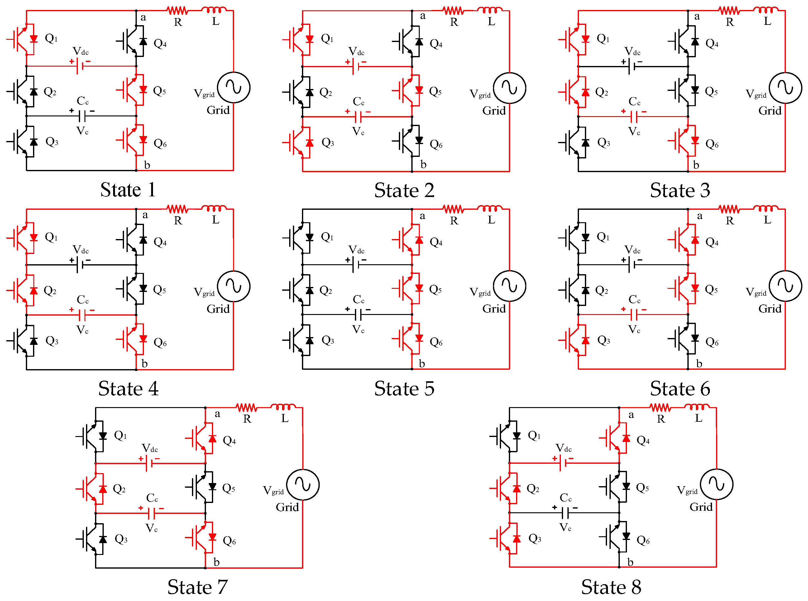
The operating states of the microinverter based on its switching levels are given in Figure 13. Operating States 1–3 generate the positive voltage levels of the microinverter. In State 1 (Vab = Vdc), switches Q1, Q5 and Q6 are conducting to form the first level, and the output voltage Vab is equal to the Vdc voltage. In State 2 (Vab = Vdc − VC), switches Q1, Q3, and Q5 are conducting, resulting in the Vdc-VC output voltage. In State 3 (Vab = VC), switches Q1, Q2 and Q6 are conducting, and the output voltage Vab is equal to VC. The switches Q1, Q2 and Q3 in State 4 and Q4, Q5 and Q6 in State 5 are conducting to form the zero-voltage level.
Figure 13.
Operating States According to Switching Levels.
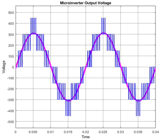
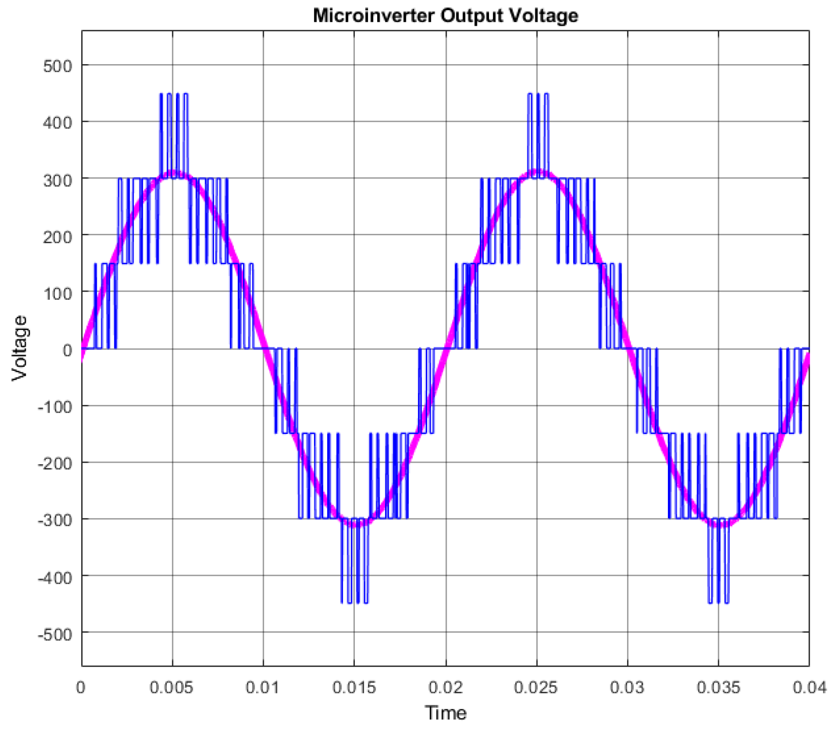
The Operating States 6–8 presented in Figure 13 generate the negative voltage levels of the microinverter. In State 6, the −VC voltage is obtained at the output by switching Q3, Q4 and Q5 to the ON state. In State 7, the output voltage level becomes VC − Vdc by switching Q2, Q4 and Q6 to the ON state. In State 8, switches Q2, Q3 and Q4 are in the ON state, and the output voltage becomes −Vdc. The microinverter output voltage levels corresponding to the operating states given in Figure 13 are provided in Figure 14. As illustrated in Figure 14, the blue waveforms represent the 7-level switching signal output, while the pink lines denote the filter output voltage.
Figure 14.
Microinverter Output Voltage.
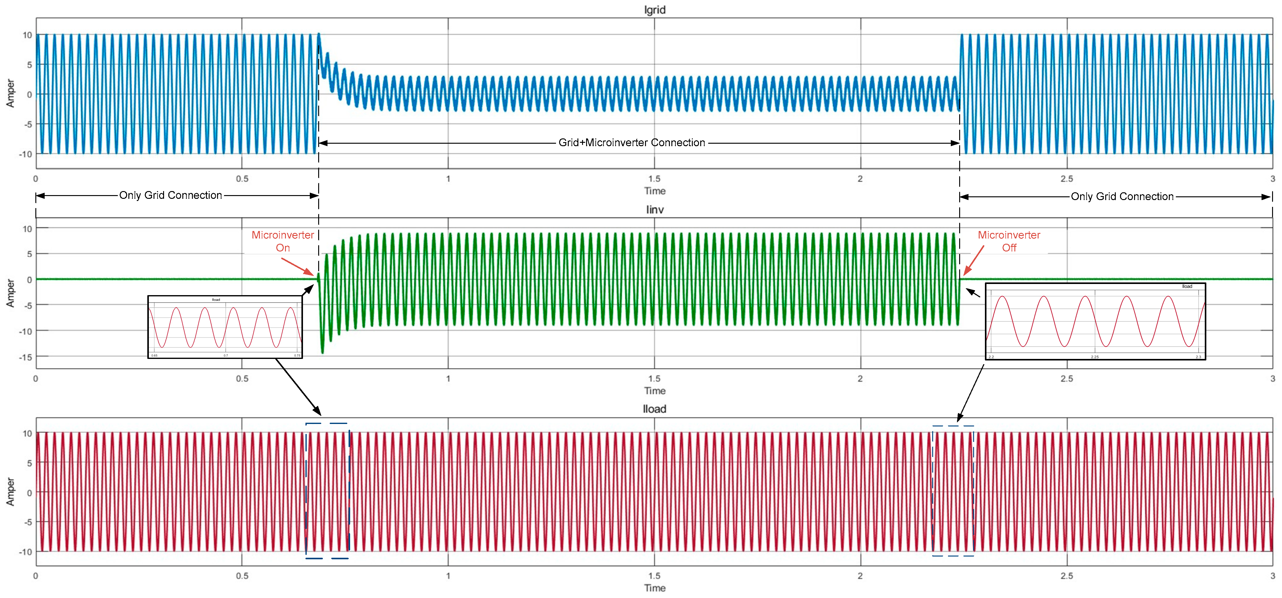
The synchronous parallel connection of the seven-level PUC inverter with the local grid and its effect on the load supply characteristic are presented in detail with oscilloscope traces in Figure 15. This synchronization is fundamentally based on the continuous assurance of precise phase alignment between the grid voltage and the inverter output voltage via the Phase-Locked Loop (PLL) module. The performance analysis conducted investigates three fundamental operating states representing the grid-interactive operating regime:
Figure 15.
Grid and Microinverter Connection.
State I (Grid Supply): The initial state where the entire load is supplied solely by the local grid.
State II (Hybrid Supply): The regime where the microinverter engages, injecting active power to meet local load demand, and the load is simultaneously and synchronously supplied by both the grid and the microinverter.
State III (Return to Grid): The final state where the microinverter disengages, and the load transitions back to being supplied solely by the grid.
The measurement results in Figure 15 clearly show that as the microinverter engages in parallel connection (marked by the formation of the Iinv current) at a t of approx. 0.65 s, the amplitude of the current drawn from the grid (Igrid) significantly decreases, thereby relieving the load on the grid. This reduction proves the microinverter’s direct and instantaneous contribution to active power sharing supplied to the load. Most importantly, despite these dynamic transients during the microinverter’s engagement (t approx. 0.65 s) and disengagement (t 2.25 s), the amplitude and sinusoidal form of the load current (Iload) are maintained, confirming that the continuity and quality of the load supply are minimally affected by these dynamic transitions.
These findings demonstrate the seven-level PUC inverter’s ability to minimize voltage/current ripple on the load and reveal the stability of the control, utilizing the advantages of fast current control and high switching frequency even in grid-supported operation. Thus, microinverter technology not only increases energy conversion efficiency but also directly contributes to broad sustainable development goals such as the high-reliability integration of renewable sources into the grid, the reduction in carbon emissions, and the strengthening of energy supply security.
3.6. Communication Infrastructure: WSN
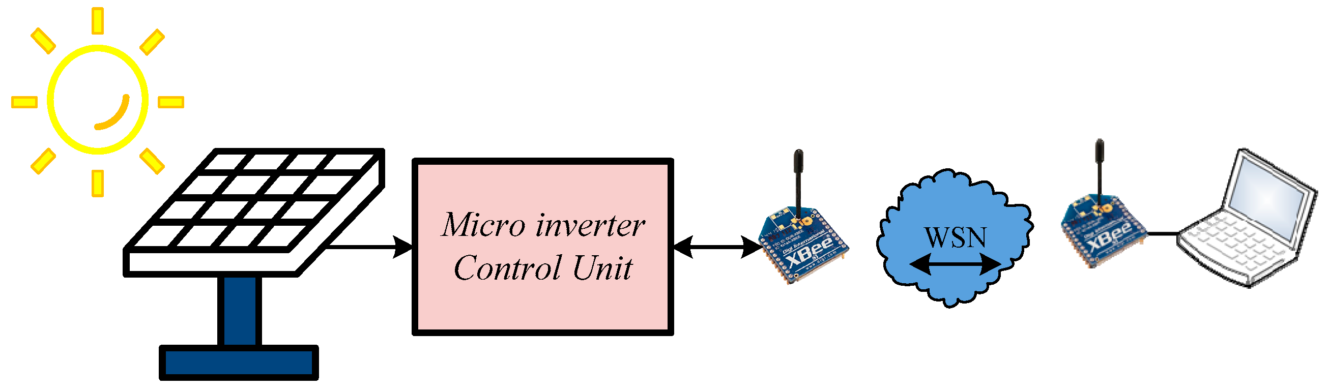
The full realization of the high efficiency, flexibility, and modularity potential of microinverter-based PV systems is contingent upon a reliable and bidirectional communication infrastructure. Unlike conventional centralized systems, the communication mechanism enables real-time performance tracking at the individual panel level, thereby facilitating the instantaneous identification of localized loss mechanisms such as shading, soiling, or hardware faults. This detailed visibility significantly mitigates the system’s operation and maintenance (O&M) costs. In this context, communication protocols do not only serve for data acquisition; they also permit the centralized management of vital safety functions such as remote software updates and rapid shutdown in emergencies. In the context of smart grid integration, communication between inverters and with the grid is mandated for the system’s active participation in reactive power support, frequency regulation, and demand-response programs. Consequently, the design and selection of the communication infrastructure ensure that microinverters are not merely energy conversion devices but serve as critical intelligent nodes for Distributed Energy Resources (DER) management.
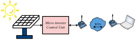
The demands for high efficiency and advanced power quality have elevated the communication infrastructure to a critical design parameter in power conversion systems. The DA-based qSB-SC MPPT topology utilized in this study optimally harvests energy from independently producing PV sources, while the seven-level PUC inverter minimizes the harmonic distortion of the injected current to enhance power quality. To monitor and manage the optimum performance criteria of this energy conversion system, which fundamentally consists of these two stages, a reliable and low-power communication network designed with ZigBee wireless communication modules has been developed. The communication infrastructure of the proposed system is presented in Figure 16.
Figure 16.
Communication infrastructure of the proposed system.
Beyond simple data monitoring, this ZigBee-based infrastructure is functionally integrated into the optimization loop as a provider of ‘Swarm Memory.’ Standard metaheuristic MPPT algorithms often suffer from a ‘cold start’ problem, where particles are distributed randomly, leading to longer search times under CPSCs. The proposed system utilizes the ZigBee network to retrieve historical irradiance and shading patterns stored in the central management unit to perform Memory-Based Initialization. By matching current sensor inputs with this historical data via the bidirectional ZigBee link, the initial dragonfly population is strategically placed near the most probable GMPP region rather than at random. This hardware–communication synergy is the fundamental reason the system achieves an ultra-fast convergence speed of 0.026 s, which would be physically unattainable through a standalone, non-communicative algorithm. The ZigBee protocol enables real-time MPPT optimization and fault detection at the panel level by relaying performance data from every microinverter to the central unit. Moreover, the central controller uses this communication network to synchronize the PUC inverter’s multilevel switching patterns and grid-supporting functions, ensuring the system maintains full compliance with grid standards and high efficiency. Ultimately, this integrated communication across the boosting, conversion, and control layers lays the essential groundwork for system stability and effective interaction with smart grids.
4. Experimental Results
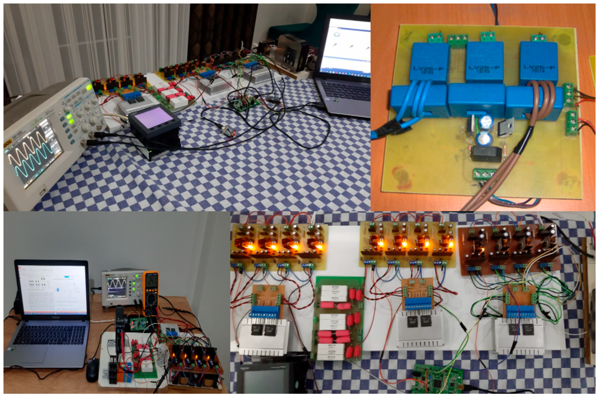
The experimental setup of the proposed DA-based qSB-SC MPPT, seven-level PUC microinverter, and ZigBee-based WSN model developed in this study is presented in Figure 17.
Figure 17.
Overview of the experimental study.
The real-time control loop was executed on the STM32F407VG Discovery microcontroller running at a clock frequency of 168 MHz. Thanks to the high-speed processing capabilities of the Cortex-M4 core, the entire modified DA optimization sequence—including sensor data acquisition via 12-bit ADCs and ZigBee-based data exchange—was completed well within the 100 µs control interrupt period. This high computational efficiency ensures that the algorithm utilizes less than 12% of the total CPU bandwidth, thereby leaving significant headroom for grid synchronization tasks and seven-level PUC switching logic.
All critical operating parameters related to the designed system are transferred in real-time to the main control unit via the WSN established with ZigBee modules. This central control unit records the performance data of every distributed PV module connected via WSN into a time-stamped database, generating instantaneous alert messages for fault conditions, efficiency drop scenarios, and supporting predictive maintenance in addition to reactive fault detection. Furthermore, this large dataset (big data) transferred to the main control unit provides a comprehensive foundation for real-time monitoring and historical analyses.
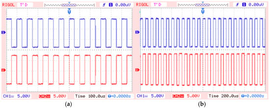
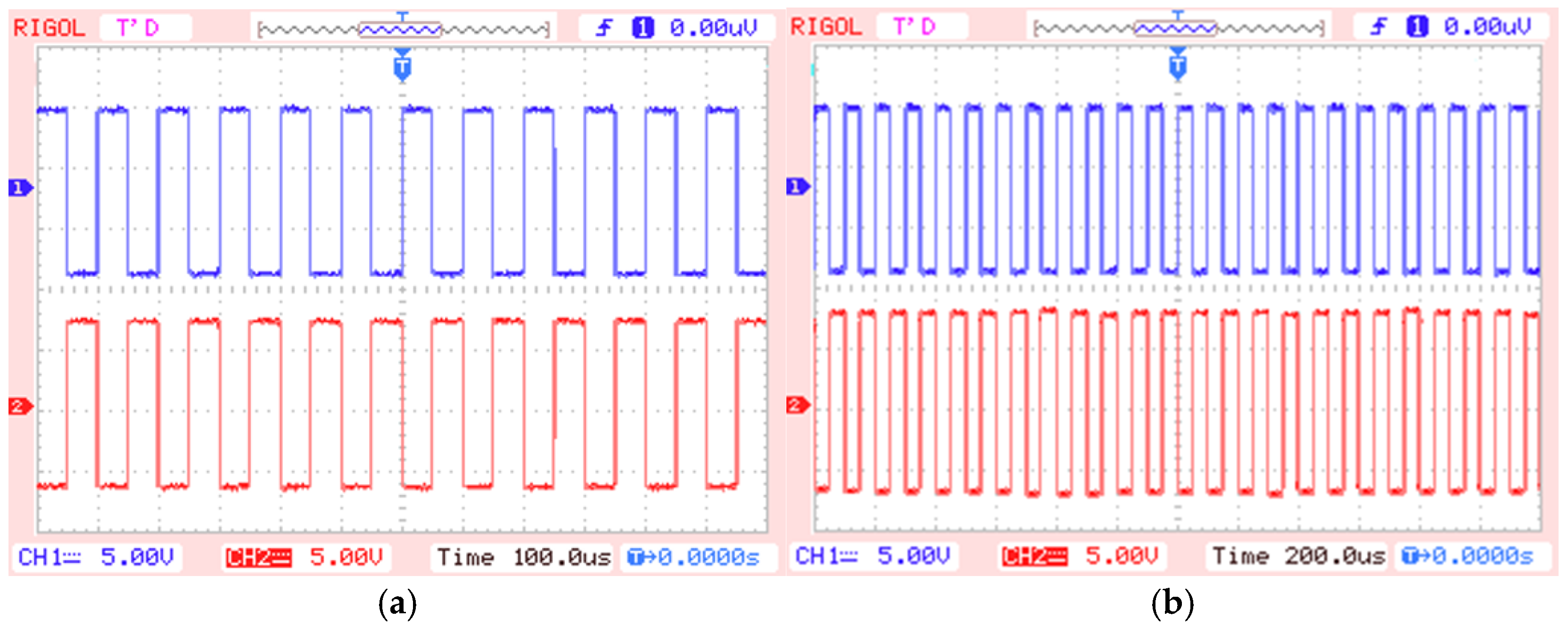
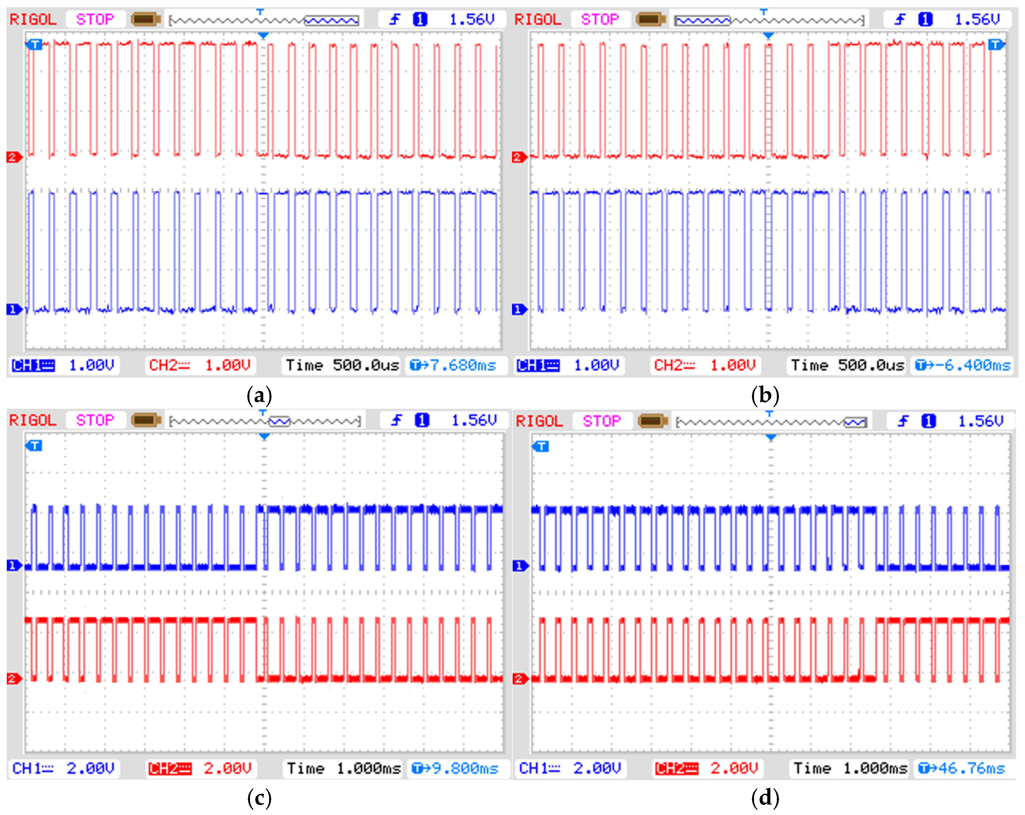
To validate the control integrity and reliability of this system, oscilloscope traces of the essential power electronic circuits are presented. The oscilloscope screen captures of the switching signals used in the DA-based qSB-SC MPPT circuit are shown in Figure 18a,b, verifying the duty cycle and frequency information of the converter. In addition, the switching signals of the seven-level PUC microinverter are presented in Figure 19a–d, where the consistency and timing of the multilevel PWM patterns that synthesize the seven-level output voltage are observed. These traces directly confirm the successful hardware implementation of the control algorithm and the resulting power quality.
Figure 18.
DA-based qSB-SC MPPT switching signals. (a) Mode 2 S2 and S3, (b) Mode3 S2 and S3.
Figure 19.
Seven-level PUC microinverter switching signals (a) Q1–Q4, (b) Q2–Q5, (c) and (d) Q3–Q6.
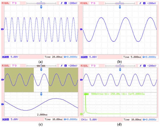
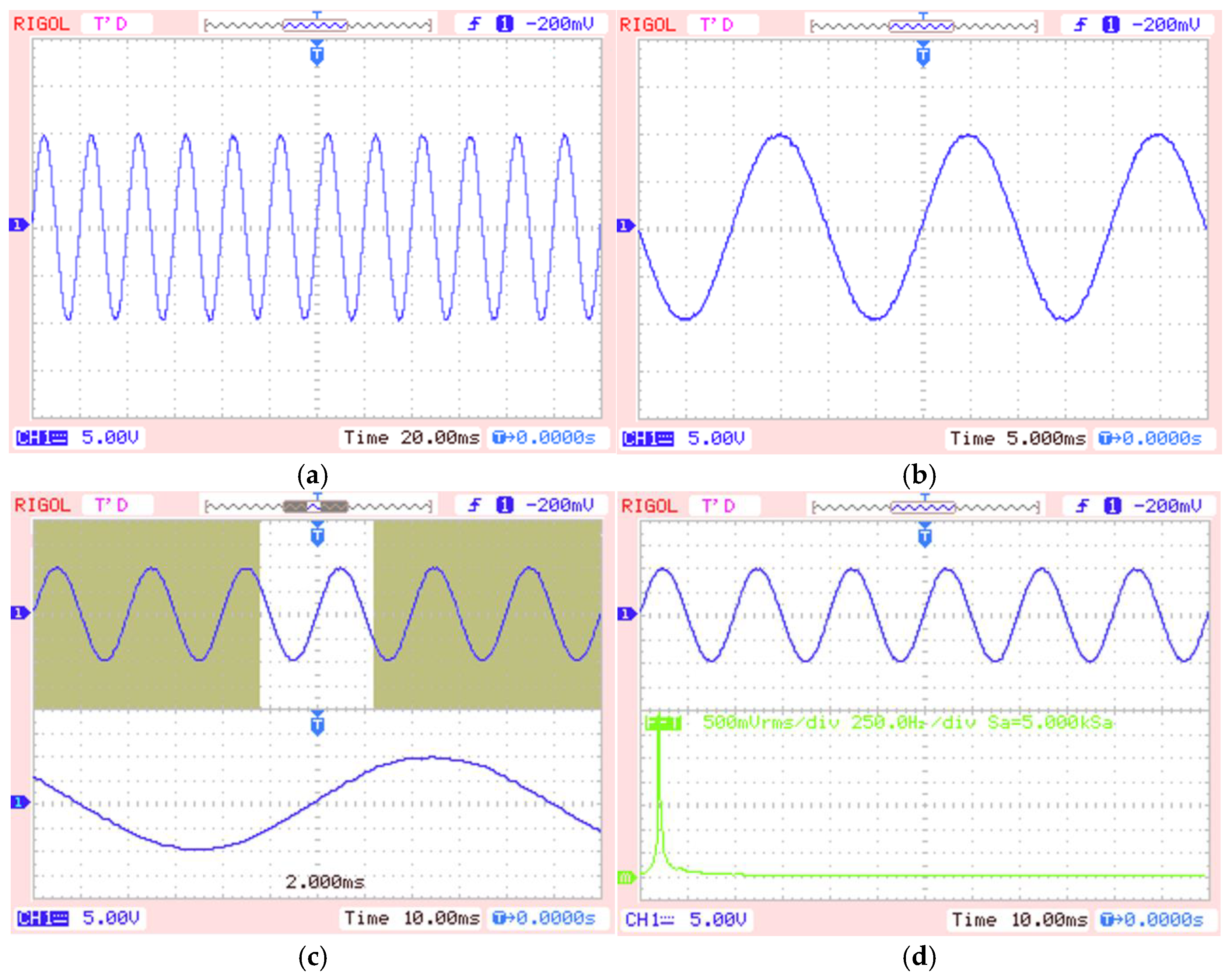
Figure 20 comprehensively presents the performance of the seven-level PUC microinverter in its grid-interactive operating regime. Figure 20a confirms the pure sinusoidal form of the grid voltage, while Figure 20b displays the inverter output voltage, demonstrating that the inverter maintains precise phase synchronization with the grid. Figure 20c shows the resulting voltage waveform across the load, and Figure 20d contains the Fast Fourier Transform (FFT) analysis of this voltage. The THD value measured across the load during the system’s laboratory implementation phase was determined to be 3.36%. This result strongly validates the effectiveness of the developed multilevel PWM control strategy and the LCL filter design. The obtained 3.36% THD value is well below the critical 5% THD limit stipulated by industry standards for grid-interactive Distributed Energy Resources. This clearly demonstrates that the microinverter successfully meets the harmonic limits prescribed by international interconnection standards such as IEEE 1547 and IEC 61727, ensuring a reliable and high-quality grid integration.
Figure 20.
The performance of the seven-level PUC microinverter (a) Pure sinusoidal form of the grid voltage, (b) Inverter output voltage, (c) Voltage waveform across the load, (d) Fast Fourier Transform (FFT) analysis.
5. Conclusions
An advanced control architecture that integrates a DA-based qSB-SC MPPT stage with a seven-level PUC microinverter and a ZigBee-based WSN to improve the efficiency and reliability of PV systems operating under PSC has been presented. Results from both simulations and real-time laboratory implementation confirm the performance advantages of the proposed system.
The modified DA consistently located the GMPP without becoming trapped at local maxima on multi-peak P–V curves. The fastest measured tracking time was 0.026 s, demonstrating strong dynamic response during transients. In a steady state, the controller exhibited only small oscillations, maximizing energy harvest and closely matching the theoretical ideal-efficiency profile.
The power-conversion stage maintained a constant 400 V DC-bus voltage using a multilevel PWM strategy. The measured load current THD was 3.36%, well below the 5% limit commonly required for grid-interactive distributed energy resources, indicating reliable grid integration and compliance with standards such as IEEE 1547 and IEC 61727.
Integrating the ZigBee-based WSN enables module-level real-time monitoring and supports predictive maintenance, reducing stress on converter components and improving system longevity.
Overall, the results indicate that microinverter-based architectures can increase energy-conversion efficiency while providing a scalable control-and-communication framework for future smart-grid infrastructures. By facilitating the reliable integration of renewable generation, the proposed system contributes to reducing carbon emissions and strengthening energy-supply security.
Application value and limitations: Hardware-in-the-loop validation on the STM32F4 platform indicates readiness for practical microinverter applications. The low CPU overhead (below 12%) supports scalability for distributed energy resource (DER) management. However, the approach depends on a robust ZigBee network to preserve the swarm-memory benefit at start-up; future work will investigate fault-tolerant communication protocols to reduce this dependency.
Author Contributions
Conceptualization, methodology, formal analysis, writing—original draft preparation and visualization A.G.; supervision, administration, software and writing—review and editing M.D.; validation, investigation, resources and data curation M.D. and A.G. All authors have read and agreed to the published version of the manuscript.
Funding
This research received no external funding.
Data Availability Statement
All data underlying the results are available as part of the article and no additional source data are required.
Conflicts of Interest
The authors declare no conflicts of interest.
References
- Mallick, P.; Sharma, R.; Satpathy, P.R.; Thanikanti, S.B.; Nwulu, N.I. A Harmony Search Switching Matrix Algorithm for Enhanced Performance of Solar PV Arrays During Non-Uniform Irradiance Scenarios. IEEE Access 2024, 12, 40387–40411. [Google Scholar] [CrossRef] [Scilit]
- Abdulmawjood, K.; Alsadi, S.; Refaat, S.S.; Morsi, W.G. Characteristic Study of Solar Photovoltaic Array under Different Partial Shading Conditions. IEEE Access 2022, 10, 6856–6866. [Google Scholar] [CrossRef] [Scilit]
- NREL. Available online: https://www.nrel.gov/pv/interactive-cell-efficiency (accessed on 15 November 2025).
- Li, C.; Yang, Y.; Fan, F.; Xia, L.; Peng, P.; Wang, Y.; Zhang, K.; Wei, H. A Novel Methodology for Partial Shading Diagnosis Using the Electrical Parameters of Photovoltaic Strings. IEEE J. Photovolta. 2022, 12, 1027–1035. [Google Scholar] [CrossRef] [Scilit]
- Kermadi, M.; Salam, Z.; Ahmed, J.; Berkouk, E.M. An Effective Hybrid Maximum Power Point Tracker of Photovoltaic Arrays for Complex Partial Shading Conditions. IEEE Trans. Ind. Electron. 2019, 66, 6990–7000. [Google Scholar] [CrossRef] [Scilit]
- Seapan, M.; Hishikawa, Y.; Yoshita, M.; Okajima, K. Detection of Shading Effect by Using the Current and Voltage at Maximum Power Point of Crystalline Silicon PV Modules. Sol. Energy 2020, 211, 1365–1372. [Google Scholar] [CrossRef] [Scilit]
- Sullivan, C.R.; Awerbuch, J.; Latham, A.M. Decrease in Photovoltaic Power Output from Ripple: Simple General Calculation and Effect of Partial Shading. In IEEE Transactions on Power Electronics; IEEE: New York, NY, USA, 2013; pp. 740–747. [Google Scholar] [CrossRef] [Scilit]
- Sun, Y.; Liu, Y.; Su, M.; Xiong, W.; Yang, J. Review of Active Power Decoupling Topologies in Single-Phase Systems. IEEE Trans. Power Electron. 2016, 31, 4778–4794. [Google Scholar] [CrossRef] [Scilit]
- Ibrahim, A.W.; Xu, J.; Farh, H.M.H.; Kandil, T.; Al-Shamma’a, A.A.; Dagal, I.; El-Shahat, A. A Comprehensive Comparison and Assessment of Global Power Extraction Techniques of Partially Shaded PV System. Electr. Eng. 2025, 107, 13617–13651. [Google Scholar] [CrossRef] [Scilit]
- Worku, M.Y.; Hassan, M.A.; Maraaba, L.S.; Shafiullah, M.; Elkadeem, M.R.; Hossain, M.I.; Abido, M.A. A Comprehensive Review of Recent Maximum Power Point Tracking Techniques for Photovoltaic Systems under Partial Shading. Sustainability 2023, 15, 11132. [Google Scholar] [CrossRef] [Scilit]
- Verma, P.; Alam, A.; Sarwar, A.; Tariq, M.; Vahedi, H.; Gupta, D.; Ahmad, S.; Adamali Shah, N.M. Meta-Heuristic Optimization Techniques Used for Maximum Power Point Tracking in Solar Pv System. Electronics 2021, 10, 2419. [Google Scholar] [CrossRef] [Scilit]
- Rukhsar; Ajmal, A.M.; Yang, Y. Global Maximum Power Point Tracking of Photovoltaic Systems Using Artificial Intelligence. Energies 2025, 18, 3036. [Google Scholar] [CrossRef] [Scilit]
- Bui, V.H.; Ha, V.D.; Truong, V.A.; Duong, T.L. A Hybrid P&O and PV Characteristics Simulation Method for GMPPT in PV Systems Under Partial Shading Conditions. Sensors 2025, 25, 1908. [Google Scholar] [CrossRef] [Scilit]
- Li, Y.; Li, L.; Jiang, Y.; Gan, Y.; Zhang, J.; Yuan, S. A Novel Hybrid Maximum Power Point Tracking Technique for PV System under Complex Partial Shading Conditions in Campus Microgrid. Appl. Sci. 2023, 13, 4998. [Google Scholar] [CrossRef] [Scilit]
- Guanghua, L.; Jamro, D.; Rahimoon, A.Q.; Memon, D.A.; Bhatti, Z.; Shah, S.H.H. Comparative Analysis of GWO MPPT with Conventional Techniques in Shaded PV Arrays. Results Eng. 2025, 27, 106881. [Google Scholar] [CrossRef] [Scilit]
- Lodhi, E.; Wang, F.Y.; Xiong, G.; Mallah, G.A.; Javed, M.Y.; Tamir, T.S.; Gao, D.W. A Dragonfly Optimization Algorithm for Extracting Maximum Power of Grid-Interfaced PV Systems. Sustainability 2021, 13, 10778. [Google Scholar] [CrossRef] [Scilit]
- de Oliveira, F.M.; Brandt, M.H.M.; Salvadori, F.; Izquierdo, J.E.E.; Cavallari, M.R.; Ando Junior, O.H. Development of an MPPT-Based Genetic Algorithm for Photovoltaic Systems versus Classical MPPT Techniques in Scenarios with Partial Shading. Inventions 2024, 9, 64. [Google Scholar] [CrossRef] [Scilit]
- Guo, L.; Meng, Z.; Sun, Y.; Wang, L. A Modified Cat Swarm Optimization Based Maximum Power Point Tracking Method for Photovoltaic System under Partially Shaded Condition. Energy 2018, 144, 501–514. [Google Scholar] [CrossRef] [Scilit]
- Wu, Z.; Yu, D.; Kang, X. Application of Improved Chicken Swarm Optimization for MPPT in Photovoltaic System. Optim. Control Appl. Methods 2018, 39, 1029–1042. [Google Scholar] [CrossRef] [Scilit]
- Chao, K.H.; Zhang, S.W. An Maximum Power Point Tracker of Photovoltaic Module Arrays Based on Improved Firefly Algorithm. Sustainability 2023, 15, 8550. [Google Scholar] [CrossRef] [Scilit]
- Akram, N.; Khan, L.; Agha, S.; Hafeez, K. Global Maximum Power Point Tracking of Partially Shaded PV System Using Advanced Optimization Techniques. Energies 2022, 15, 4055. [Google Scholar] [CrossRef] [Scilit]
- Manoharan, H.; Karuppannan, S.; Chandrasekaran, K.; Barua, S. Power Quality Improvement of Grid-Connected Solar Power Plant Systems Using a Novel Fractional Order Proportional Integral Derivative Controller Technique. IET Renew. Power Gener. 2024, 18, 3268–3284. [Google Scholar] [CrossRef] [Scilit]
- Shi, J.Y.; Zhang, D.Y.; Ling, L.T.; Xue, F.; Li, Y.J.; Qin, Z.J.; Yang, T. Dual-Algorithm Maximum Power Point Tracking Control Method for Photovoltaic Systems Based on Grey Wolf Optimization and Golden-Section Optimization. J. Power Electron. 2018, 18, 841–852. [Google Scholar] [CrossRef]
- Pilakkat, D.; Kanthalakshmi, S. An Improved P&O Algorithm Integrated with Artificial Bee Colony for Photovoltaic Systems under Partial Shading Conditions. Sol. Energy 2019, 178, 37–47. [Google Scholar] [CrossRef] [Scilit]
- Huang, Y.P.; Chen, X.; Ye, C.E. A Hybrid Maximum Power Point Tracking Approach for Photovoltaic Systems under Partial Shading Conditions Using a Modified Genetic Algorithm and the Firefly Algorithm. Int. J. Photoenergy 2018, 2018, 7598653. [Google Scholar] [CrossRef] [Scilit]
- Rocha, M.V.; Sampaio, L.P.; da Silva, S.A.O. Maximum Power Point Extraction in PV Array Under Partial Shading Conditions Using GWO-Assisted Beta Method. Renew. Energy Power Qual. J. 2018, 16, 450–455. [Google Scholar] [CrossRef] [Scilit]
- Anoop, K.; Nandakumar, M. A Novel Maximum Power Point Tracking Method Based on Particle Swarm Optimization Combined with One Cycle Control. In Proceedings of the 2018 International Conference on Power, Instrumentation, Control and Computing (PICC), Thrissur, India, 18–20 January 2018; pp. 1–6. [Google Scholar] [CrossRef] [Scilit]
- Peng, B.R.; Ho, K.C.; Liu, Y.H. A Novel and Fast MPPT Method Suitable for Both Fast Changing and Partially Shaded Conditions. IEEE Trans. Ind. Electron. 2018, 65, 3240–3251. [Google Scholar] [CrossRef] [Scilit]
- Deliu, A.D.; Cazacu, E.; Deliu, F.; Popa, C.; Popa, N.S.; Preda, M. Dynamic Average-Value Modeling and Stability of Shipboard PV–Battery Converters with Curve-Scanning Global MPPT. Electricity 2025, 6, 66. [Google Scholar] [CrossRef] [Scilit]
- Derbeli, M.; Napole, C.; Barambones, O.; Sanchez, J.; Calvo, I.; Fernández-Bustamante, P. Maximum Power Point Tracking Techniques for Photovoltaic Panel: A Review and Experimental Applications. Energies 2021, 14, 7806. [Google Scholar] [CrossRef] [Scilit]
- Palma, L. Push-Pull Based Single Stage PV Microinverter for Grid-Tied Modules. In Proceedings of the 2016 International Symposium on Power Electronics, Electrical Drives, Automation and Motion (SPEEDAM), Capri, Italy, 22–24 June 2016; IEEE: New York, NY, USA, 2016; pp. 884–888. [Google Scholar]
- Nezamuddin, O.; Crespo, J.; dos Santos, E.C. Design of a Highly Efficient Microinverter. In Proceedings of the 2016 IEEE 43rd Photovoltaic Specialists Conference (PVSC), Portland, OR, USA, 5–10 June 2016; IEEE: New York, NY, USA, 2016; pp. 3463–3468. [Google Scholar]
- Dursun, M.; Gorgun, A. A Micro Inverter Design for Micro Grids. In Proceedings of the 2020 7th International Conference on Electrical and Electronics Engineering, ICEEE 2020, Antalya, Turkey, 14–16 April 2020; IEEE: New York, NY, USA, 2020; pp. 120–125. [Google Scholar]
- IEEE 1547.2-2023; IEEE Application Guide for IEEE Std 1547™-2018, IEEE Standard for Interconnection and Interoperability of Distributed Energy Resources with Associated Electric Power Systems Interfaces. IEEE: Piscataway, NJ, USA, 2023. Available online: https://standards.ieee.org/ieee/1547.2/7166/ (accessed on 15 November 2025).
- IEC61727:2004; Photovoltaic (PV) Systems—Characteristics of the Utility Interface. International Electrotechnical Commission (IEC): Geneva, Switzerland, 2004. Available online: https://webstore.iec.ch/en/publication/5736 (accessed on 15 November 2025).
- Dursun, M.; Gorgun, A. Analysis and Performance Comparison of DC-DC Power Converters Used in Photovoltaic Systems. In Proceedings of the 2017 4th International Conference on Electrical and Electronic Engineering (ICEEE), Ankara, Turkey, 8–10 April 2017; IEEE: New York, NY, USA, 2017; pp. 113–119. [Google Scholar]
- Podder, A.K.; Roy, N.K.; Pota, H.R. MPPT Methods for Solar PV Systems: A Critical Review Based on Tracking Nature. IET Renew. Power Gener. 2019, 13, 1615–1632. [Google Scholar] [CrossRef] [Scilit]
- Duffie, J.A.; Beckman, W.A. Solar Engineering of Thermal Processes, 4th ed.; John Wiley & Sons, Inc.: Hoboken, NJ, USA, 2013. [Google Scholar] [CrossRef] [Scilit]
- Brinkworth, B.J.; Sandberg, M. Design Procedure for Cooling Ducts to Minimise Efficiency Loss Due to Temperature Rise in PV Arrays. Sol. Energy 2006, 80, 89–103. [Google Scholar] [CrossRef] [Scilit]
- Hohm, D.P.; Ropp, M.E. Comparative Study of Maximum Power Point Tracking Algorithms. Prog. Photovolta. Res. Appl. 2003, 11, 47–62. [Google Scholar] [CrossRef] [Scilit]
- Villalva, M.G.; Gazoli, J.R.; Filho, E.R. Comprehensive Approach to Modeling and Simulation of Photovoltaic Arrays. IEEE Trans. Power Electron. 2009, 24, 1198–1208. [Google Scholar] [CrossRef] [Scilit]
- Guiavarch, A.; Peuportier, B. Photovoltaic Collectors Efficiency According to Their Integration in Buildings. Sol. Energy 2006, 80, 65–77. [Google Scholar] [CrossRef] [Scilit]
- De Soto, W.; Klein, S.A.; Beckman, W.A. Improvement and Validation of a Model for Photovoltaic Array Performance. Sol. Energy 2006, 80, 78–88. [Google Scholar] [CrossRef] [Scilit]
- Lasseter, R.H.; Chen, Z.; Pattabiraman, D. Grid-Forming Inverters: A Critical Asset for the Power Grid. IEEE J. Emerg. Sel. Top. Power Electron. 2020, 8, 925–935. [Google Scholar] [CrossRef] [Scilit]
- Mirjalili, S. Dragonfly Algorithm: A New Meta-Heuristic Optimization Technique for Solving Single-Objective, Discrete, and Multi-Objective Problems. Neural Comput. Appl. 2016, 27, 1053–1073. [Google Scholar] [CrossRef] [Scilit]
- Rahman, C.M.; Rashid, T.A. Dragonfly Algorithm and Its Applications in Applied Science Survey. Comput. Intell. Neurosci. 2019, 2019, 9293617. [Google Scholar] [CrossRef] [Scilit]
- SeyedShenava, S.J.; Zare, P.; Davoudkhani, I.F. Maximizing Solar Energy Harvesting Efficiency: Optimal Hybrid Deep Neural Learning—Based MPPT for Photovoltaic Systems under Complex Partial Shading Conditions. Sustain. Comput. Inform. Syst. 2025, 47, 101159. [Google Scholar] [CrossRef] [Scilit]
- Belhachat, F.; Larbes, C. A Review of Global Maximum Power Point Tracking Techniques of Photovoltaic System under Partial Shading Conditions. Renew. Sustain. Energy Rev. 2018, 92, 513–553. [Google Scholar] [CrossRef] [Scilit]
- Wasim, M.S.; Amjad, M.; Habib, S.; Abbasi, M.A.; Bhatti, A.R.; Muyeen, S.M. A Critical Review and Performance Comparisons of Swarm-Based Optimization Algorithms in Maximum Power Point Tracking of Photovoltaic Systems under Partial Shading Conditions. Energy Rep. 2022, 8, 4871–4898. [Google Scholar] [CrossRef] [Scilit]
- Paul, P.; Jose, B.R.; Shahana, T.K.; Abraham, C.; Mathew, J. Design and Analysis of a Dual Input Quasi SB-SC Cell High Gain Converter. Int. J. Electron. 2024, 111, 877–894. [Google Scholar] [CrossRef] [Scilit]
- Paul, P.; Jose, B.R.; Shahana, T.K.; Abraham, C.; Mathew, J.; Sandeep, J. Push-Pull Based Grid Tied Micro Inverter for Photovoltaic Applications. In Proceedings of the 2023 IEEE International Conference on Power Electronics, Smart Grid, and Renewable Energy (PESGRE), Trivandrum, India, 17–20 December 2023. [Google Scholar] [CrossRef] [Scilit]
- Famoso, F.; Lanzafame, R.; Maenza, S.; Scandura, P.F. Performance Comparison between Micro-Inverter and String-Inverter Photovoltaic Systems. Energy Procedia 2015, 81, 526–539. [Google Scholar] [CrossRef] [Scilit]
- Yu, B. Anti-Islanding Performance Analysis of Multiple PV Micro-Inverter Operations. IETE J. Res. 2018, 64, 785–795. [Google Scholar] [CrossRef] [Scilit]
- Bi, K.; Wang, C.; Ai, J.; Wu, F.; Li, J.; Fan, Q. Quasi-Single-Stage Micro-Inverter Based on Discrete Capacitor Resonant DAB and Its Control Strategy. In IEEE Transactions on Power Electronics; IEEE: New York, NY, USA, 2025. [Google Scholar] [CrossRef] [Scilit]
- Dursun, M.; Görgun, A. Micro Inverter Design for Micro Grids and Communication Application with Wireless Sensor Network in Micro Environments. In Proceedings of the 2025 International Conference on Control, Automation and Diagnosis (ICCAD), Barcelona, Spain, 1–3 July 2025. [Google Scholar] [CrossRef] [Scilit]




Disclaimer/Publisher’s Note: The statements, opinions and data contained in all publications are solely those of the individual author(s) and contributor(s) and not of MDPI and/or the editor(s). MDPI and/or the editor(s) disclaim responsibility for any injury to people or property resulting from any ideas, methods, instructions or products referred to in the content. |
© 2026 by the authors. Licensee MDPI, Basel, Switzerland. This article is an open access article distributed under the terms and conditions of the Creative Commons Attribution (CC BY) license.