Article

CVD-Grown CNTs on Basalt Fiber Surfaces for Multifunctional Composite Interphases

1
Leibniz-Institut für Polymerforschung Dresden e.V., Dresden D-01069, Germany
2
The Xinjiang Technical Institute of Physics and Chemistry, Chinese Academy of Sciences, Urumqi 830011, China
*
Author to whom correspondence should be addressed.
Fibers 2016, 4(4), 28; https://doi.org/10.3390/fib4040028
Submission received: 5 September 2016 / Revised: 8 November 2016 / Accepted: 10 November 2016 / Published: 23 November 2016
(This article belongs to the Special Issue Glass Fibers)

Abstract

:
Chemical vapor deposition (CVD) is used as a method for the synthesis of carbon nanotubes (CNT) on substrates, most commonly pre-treated by a metal-catalyst. In this work, the capability of basalt fiber surfaces was investigated in order to stimulate catalyst-free growth of carbon nanotubes. We have carried out CVD experiments on unsized, sized, and NaOH-treated basalt fibers modified by growth temperature and a process gas mixture. Subsequently, we investigated the fiber surfaces by SEM, AFM, XPS and carried out single fiber tensile tests. Growth temperatures of 700 °C as well as 800 °C may induce CNT growth, but depending on the basalt fiber surface, the growth process was differently affected. The XPS results suggest surficial iron is not crucial for the CNT growth. We demonstrate that the formation of a corrosion shell is able to support CNT networks. However, our investigations do not expose distinctively the mechanisms by which unsized basalt fibers sometimes induce vertically aligned CNT carpets, isotropically arranged CNTs or no CNT growth. Considering data from the literature and our AFM results, it is assumed that the nano-roughness of surfaces could be a critical parameter for CNT growth. These findings will motivate the design of future experiments to discover the role of surface roughness as well as surface defects on the formation of hierarchical interphases.

1. Introduction

Effective surface treatment of reinforcement fibers is a key task in order to tailor composite interphases and to improve composite strength and toughness. Currently, nanomaterials are often used to achieve multifunctional interphases, in other words, to implement electrical, chemical, or thermal functions in addition to the mechanical functions. Recycling of fiber reinforced polymers is also in the focus of several investigations. Chemical and thermal treatments of composites are the common way to separate the reinforcing fibers from the polymer matrices. However, most sizings on glass and basalt fibers do not resist high temperatures. Hence, a heat treatment might also lead to sizing removal, a decrease of mechanical performance, and deterioration in the fiber-matrix adhesion. Thomason et al. [1] highlighted thermal recycling as the most advanced recycling technology, but underline the drawback due to the cost competitiveness of recycled fibers. The drop in the performance is 80%–90% compared to that in the original state. Furthermore, the poor performance to cost ratio as well as difficulties in the reprocessing of recycled fibers are itemized and considered as obstacles for the valuable reuse as reinforcement material. In the case of thermal recycled glass fibers, Thomason [1] pointed out that the regeneration of properties would have a major impact in all matters technological, societal, economical, and environmental. Thus, recently, the willingness to follow new approaches in order to find innovative solutions for upgrading fiber properties increases. Besides the strength regeneration and fiber reprocessing, the recycling technique itself and the surface reactivation are mentioned by Yang et al. [2] as the major technical barriers that have to be overcome. In [2], the effectiveness of thermal and chemical treated E-glass fibers and corresponding composite properties are investigated. After a heat-treatment at 500 °C, the tensile strength of the boron-free E-glass fibers is decreased by about 80%, and the apparent interfacial shear strength (IFSS) in glass fiber-modified polypropylene is lowered by about 50%. Due to a post-silanisation based on 1% γ-aminopropylsilane (APS) the IFSS of the as-received fibers is almost reconstituted. However, the silanisation has been reported to be less effective on the fiber tensile strength. Interestingly, the chemical etching based on hydrofluoric acid (HF) aqueous solution and a post-silanisation led to a smaller loss in tensile strength and moderate IFSS.
In our previous work, we showed that the type of organosilane used in sizings applied during the fiberizing is able to affect the characteristic fiber strength [3]. Therefore, re-sizing or “post-silanisation” with suitable organosilanes is considered a promising approach for the surface modification of recycled basalt as well as glass fibers. For a long time, the thermal de-sizing of glass fiber fabrics coated with starch-oil based sizings and the subsequent re-sizing with silanes has been a common practice to improve the performance of fiber reinforced plastics. Recently, interphase approaches have been more and more focused on both the improvement of the mechanical performance of composites as well as the implementation of additional functions in order to create multifunctional composites. Bismarck et al., for example, reported on responsive fiber coatings with the objective to achieve composites with variable and/or controllable stiffness [4,5]. In our previous work based on glass fibers, many sensor utilities have switched to highly sensitive multifunctional carbon nanoparticle systems that can realize response properties due to their novel electronic properties. This advance has resulted in smart composite interphases, variations of the material properties, and stimulated response to changes in the external environment (temperature, strain/stress, relative humidity) for structural application [6,7,8]. Despite its potential, warning of structural failure remains one of the most challenging tasks to make the new generation of materials safer in materials science. The performance of multiscale composites, including both micro and nano-scale reinforcing materials, have been effective for advanced properties [9,10]. Only a few studies have been conducted which consider basalt fiber-reinforced multiscale composites. An increase of tensile strength and Young’s modulus was reported by Lee et al. [11]. More recently, the influence of surface functionality of CNT on the mechanical properties of basalt fiber-reinforced multiscale composites was studied in [12,13]. However, it should be noted that both used epoxy resin mixed with carbon nanotubes (CNTs) instead of CNT-modified fiber surfaces.
In this work we focus on another more non-conventional route, the surface treatment by chemical vapor deposition (CVD) on basalt fibers without catalysts, in order to initiate hierarchical CNT architectures. If successful, the multifunctional interphase approach, as investigated with glass fibers, could also reveal recycling strategies and contribute to upgrading the properties of recycled basalt fibers or, rather, the properties of 2nd-life composites.
CVD is one of the methods used for the synthesis of high quality, high purity, and high yield CNTs with a controlled structure. In general, catalyst nanoparticles (e.g., Fe, Ni, Co), a carbon feedstock, and heat are required. The formation of carbon nanotubes or nanofibers is a consequence of the catalytic decomposition of the carbon feedstock, the diffusion of carbon, and its subsequent precipitation as graphitic carbon. Hereby, the catalytic activity of the metal particles, the formation of metastable carbides, and the manner of carbon diffusion, in particular through the metal particles (bulk diffusion) or around the metal particle (surface diffusion), are crucial. Growth models as well as the growth modes, tip-growth, and base-growth are described in more detail in [14,15]. However, it should be noted that the quality of the obtained CNTs may strongly depend on various parameters, for example, catalyst type, catalyst deposition, process gas mixture, gas flow rates, flow duration, and of course the growth temperature [16,17].
Fe, Ni, or Co is often used as a catalyst for CNTs growth. However, using catalysts has some drawbacks [18]. In terms of CNT quality and/or properties, both a temperature induced agglomeration of the catalyst particles as well as a distortion due to remaining particles within the CNTs are disadvantageous. Furthermore, metal catalyst-substrate reactions at temperatures of about 700 °C can be disadvantageous. Especially if fibers are used as a substrate, the strength properties will be affected [19].
Huang et al. [20] demonstrated that SiO2 nanoparticles generated by scratching SiO2 substrates can catalyze CNT growth. The authors postulate that almost any “small” particles are able to initiate CNT growth. Similarly, Tripathi et al. [18] assumed that any substrate with a rough surface which can bear around 700 °C is suitable to catalyze CNTs growth. The surface morphology and texture properties, the thickness of the underlayer, as well as the interactions between the substrate and the catalyst can affect the CNT quality and/or the growth rate. Silicon oxide, magnesium oxide, and alumina oxide were mentioned as the most popular underlayer materials used as CNT substrates [21]. Even glass fibers were already used as substrates [22,23]. However, in both cited studies, catalysts are applied. Commonly, the low thermal resistance of glass fibers is considered as an obstacle and are reason why glass fibers are not well suited for CNT grafting through CVD [24].
To our knowledge, no work has been published so far about using basalt fibers as a substrate for CNT growth. Basalt fibers are glass fibers rich in iron-oxide with enhanced Young’s modulus and temperature resistance compared to that of E-glass fibers. The main constituents are SiO2, Al2O3, MgO, CaO, and iron oxides. The XPS results reported in [25] showed that the major surface components of unsized basalt fibers are silicon, aluminum, and oxygen. In small amounts iron was found to be present on the fiber surface.
In the field of polyvalent element-bearing silicate glasses, in particular the investigation of cation diffusion due to heat-treatments in different atmospheres, comprehensive work was done by Smedskjaer and co-workers [26,27,28,29]. The authors observed the formation of nano layers and reported that the morphology and elemental concentration profiles are strongly influenced by the atmosphere used [26]. Previous AFM studies indicated a nanostructured surface topography if basalt fibers are wetted only with water during the drawing process or de-sized by heat treatments in air [30,31].
The nanostructure and the occurrence of catalytic elements substantiate our approach that CVD treatments on basalt fibers are able to induce catalyst-free CNT growth. That means in contrast to glass and carbon fibers, a pre-treatment with a catalyst solution could be skipped. In our first CVD experiments at the Xinjiang Technical Institute of Physics and Chemistry at the Chinese Academy of Science in Urumqi, CNT arrays, isotropic CNT networks, and fibers covered by a coating layer without CNTs were observed. Encouraged by these results and with the objective to get a better understanding of the mechanisms responsible for the initiation of CNT growth, especially for the formation of vertically aligned fiber architecture, the CVD experiments were continued.
In this work,
(i)
basalt fibers with different chemical composition,
(ii)
alkali attacked basalt fibers, and
(iii)
sized basalt fibers
were used for the CVD experiments, and its surfaces were investigated by SEM, AFM, and XPS. Furthermore, we carried out single fiber tensile tests.

2. Materials and Methods

CNT growth experiments were performed on unsized, sized, and NaOH-treated basalt fibers. Fibers denoted as BAS11, BAS16(A), BAS16(A1), and BAS16(A5) were only wetted with water during the fiber manufacturing. A1 and A5 designate an additional pre-treatment in NaOH. Therefore, unsized basalt fibers were immersed in 5% NaOH solution for 5 h at a temperature of 80 °C. After the NaOH treatment, the fibers were rinsed with diluted HCl solution and pure water, and then dried at 70 °C.
Unsized and sized basalt fibers BAS16 were supplied by Mafic Black Basalt (Ireland) Ltd., Kells, Ireland. Applied sizing is compatible with an epoxy resin matrix. Unsized basalt fibers BAS11 were supplied by Asamer Basaltic Fibers GmbH, Ohlsdorf, Austria. Table 1 displays all investigated samples.
CVD experiments were carried out at the Xinjiang Technical Institute of Physics and Chemistry Chinese Academy of Science in Urumqi using a CVD furnace system OTF-1200X-D4-80-SL (Hefei KE JING Materials Technology Co., Ltd., Hefei, China. The CVD system consists of an inner and an outer quartz tube placed inside a high temperature furnace and heated over a length of about 600 mm. The diameters of the inner and outer tubes were 80 and 94 mm, respectively. The basalt fiber bundles were fixed on the surface of the inner tube.
According to Table 2, the following CVD experiments were performed:
  • CVD01: includes treatment from stage I to VI at Ti = 800 °C
  • CVD02: includes treatment from stage I to VI, but without stage IV
  • CVD03: includes treatment from stage I to VI, at Ti = 700 °C
XPS studies were carried out by means of an Axis Ultra X-ray photoelectron spectrometer (Kratos Analytical, Manchester, UK). The spectrometer was equipped with a monochromatic Al Kα (hν = 1486.6 eV) X-ray source of 300 W at 15 kV. The kinetic energy of photoelectrons was determined with a hemispheric analyzer set to pass energy of 160 eV for wide-scan spectra and 20 eV for high-resolution spectra. During all measurements, electrostatic charging of the sample was avoided by means of a low-energy electron source working in combination with a magnetic immersion lens. Later, all recorded peaks were shifted by the same value that was necessary to set the C 1s component peak of saturated hydrocarbons to 285.00 eV. In the case of the fiber sample carrying a closed graphite-like layer (CVD01), the component peak representing sp2-hybridized carbon atoms was set to 284.00 eV. Quantitative elemental compositions were determined from peak areas using experimentally determined sensitivity factors and the spectrometer transmission function. All spectra were recorded from fiber bundles prepared over a hole in the sample holder.
Single fiber tensile tests were conducted under air-conditioning (temperature 23 °C, relative humidity 50%) by using a Favigraph semi-automatic testing device (Textechno, Mönchengladbach, Germany) equipped with a 1 N load cell. The cross head velocity was 10 mm/min and the gauge length was 20 mm. The fineness of each selected fiber was determined by using the vibroscope method in accordance with ASTM D 1577. Fifty single fibers were tested to calculate the mean values (denoted as σm) and standard deviations. Values of 2.8 g/cm3 and 2.7 g/cm3 were used as the density for the evaluation of the tensile tests of BAS11 and BAS16, respectively. In addition, tensile test results were evaluated by Weibull probability analysis. The Weibull parameters, σ0 and m, are determined by plotting ln(−ln(1 − P)) against ln(σ) and utilizing the Least Squares (LS) regression method. The scale parameter σ0 represents the stress at which 63.2% of the filaments break (P(σ0) = 0.6321). The shape parameter m, designated as the Weibull modulus, is a measure of the distribution of the failure stress and R, the coefficient of determination, describes the quality of the fit. Data evaluation applied is described more in detail in reference [3,25].
For qualitative filament surface investigation, a Scanning Electron Microscope (SEM) Ultra Plus (Zeiss, Jena, Germany) was used. Specimens were sputter coated with platinum. In addition, Atomic Force Microscopy (AFM) measurements were performed on a Dimension ICON (Bruker, St. Barbara, CA, USA) using cantilevers (Multi75Al-G, Budget Sensors, Sofia, Bulgaria). The measurements were carried out in tapping mode.

3. Results

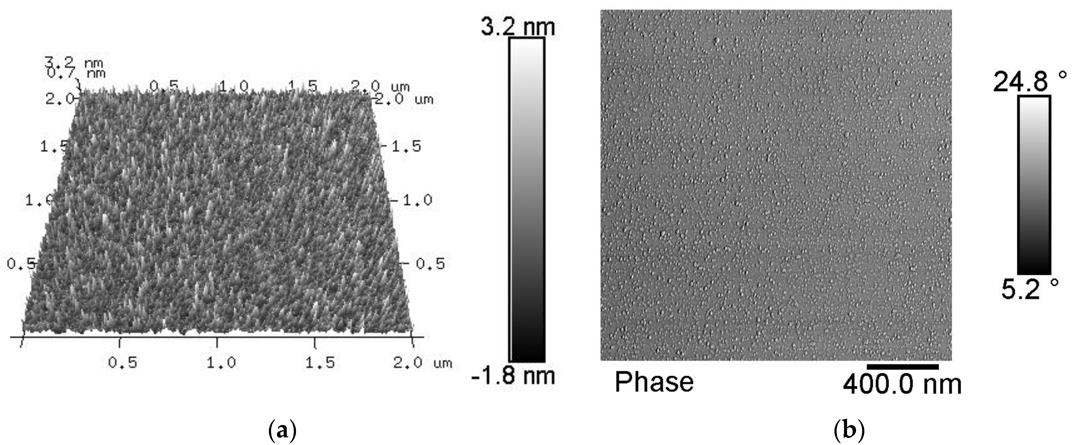
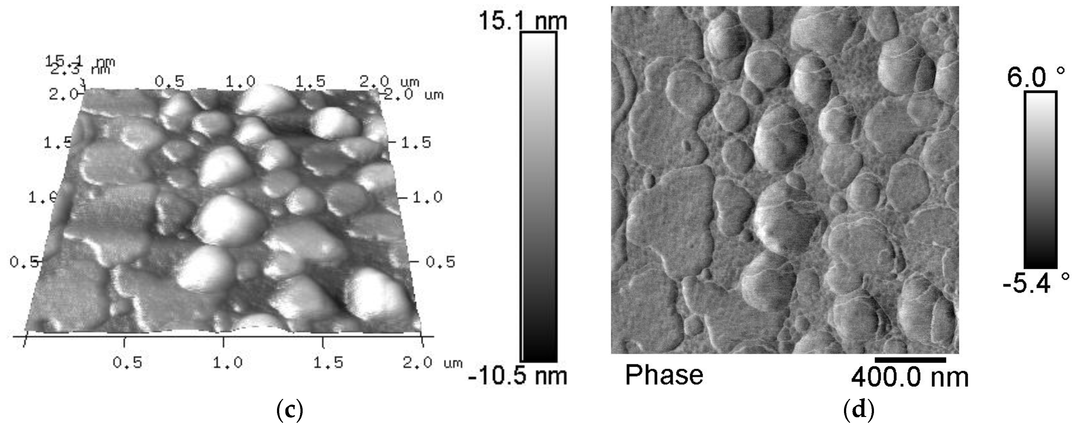
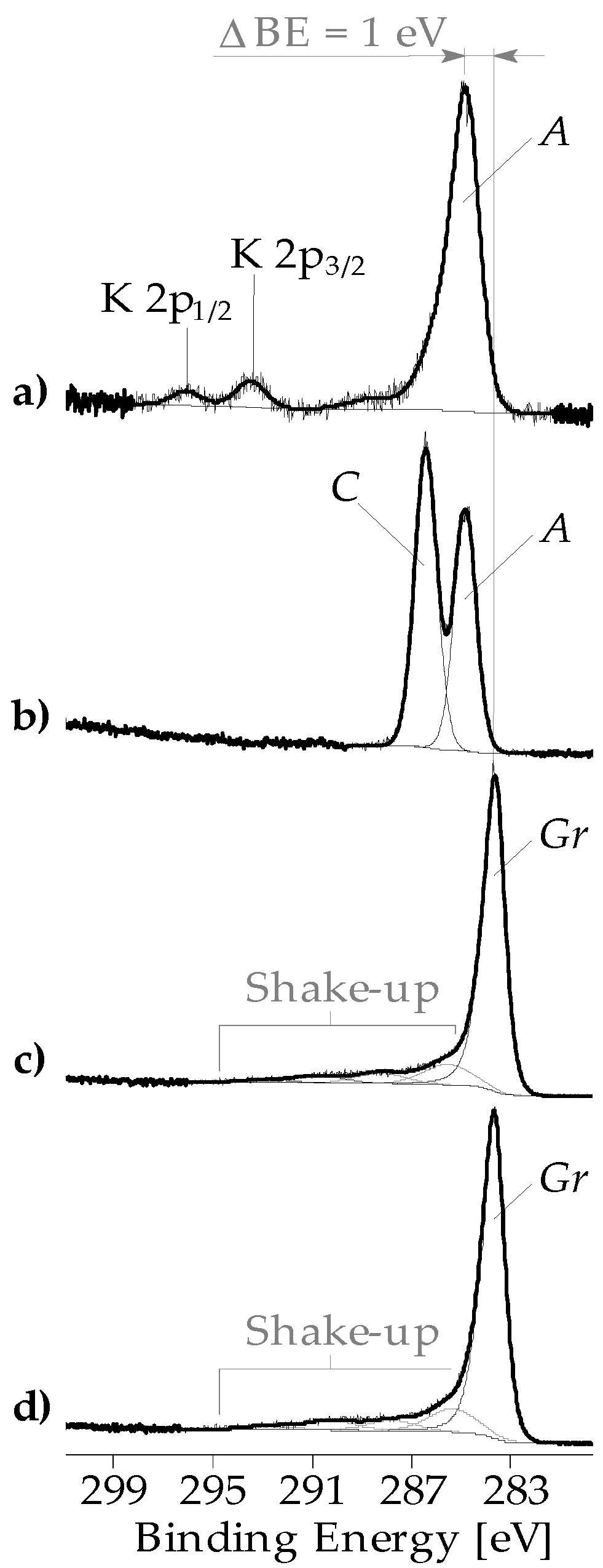
3.1. Chemical Composition of the Fiber Surfaces Before and After CVD Treatment

As expected for the basalt minerals, XPS wide-scan spectra showed silicon and aluminum, which are present in their oxides. They were accompanied by magnesium, calcium, titanium, and iron. Non-specifically adsorbed organic contaminations were identified by the C 1s peaks. The presence of such contamination layers is characteristic for oxide surfaces, which were stored or handled under ambient conditions. As can be seen in Table 3, the relative elemental surface composition of the fibers is slightly different. The depletion of aluminum and silicon, which was observed after the NaOH treatment of fiber BAS16(A), indicated the partial dissolution of the surface near the aluminosilicate phases. The corrosion shell formed in that way is visualized in Figure 1. A more detailed description of the mechanisms of the basalt fiber corrosion is provided in [32]. Based on these studies, it is assumed that carbonates are enriched in the corrosion shell.
XPS investigations confirmed the formation of carbon-rich layers during the CVD01 treatment as designated in Section 2. These precipitated layers are dense and thick so that most of the photoelectrons escaped from the atoms of the basalt substrates, were inelastically scattered, and did not contribute to the spectra recorded. Hence, elements typical for basalt were not analyzed (e.g., iron, magnesium, and calcium) or their intensities seemed to be strongly decreased (e.g., aluminum) in the XPS wide-scan spectra. The high-resolution C 1s spectra recorded from the CVD processed fiber samples indicated the presence of graphite-like carboneous species on the fiber surface (Figure 2c,d). Compared to the C 1s spectrum of a non-CVD-treated basalt fiber sample BAS16(A) (Figure 2a), which showed the predominant presence of saturated hydrocarbons, the main component peak Gr was shifted to a lower binding energy value (BE ≈ 284 eV). The binding energy value found is typical for sp2 hybridized carbon atoms forming highly ordered graphite-like lattices, which are constituents of CNT or fullerenes [33]. The wide shake-up peaks observed resulted from electron transfers between occupied π and unoccupied π* orbitals. Their appearance can be considered as evidence for delocalized p-electrons in highly conjugated π orbitals. The hydrocarbons (component peak A) of the layer contaminating the initial basalt fiber did not show the shake-up phenomena (Figure 2a). For comparison, Figure 2b shows a C 1s spectrum, which was recorded from a commercially sized basalt fiber (BAS16(A-Si)). Beside the component peak A at 285.00 eV, a second intensive component peak C was separated at 286.71 eV. This component peak represents the C–O of mainly ether and some alcohol groups, which reveal the application of an epoxy-sizing. Brønsted-acidic Si–OH groups present on the basalt surface were able to open the oxirane rings of the epoxy groups and initiate the formation of a polymeric network on the basalt fiber surface. With the exception of traces of silicon, the corresponding wide-scan spectrum of the BAS16(A-Si) sample did not show photoelectron peaks of elements appearing from the basalt substrate, such as aluminum, titanium, calcium and iron. Obviously, the polymeric network nearly homogeneously covers the fiber surface.

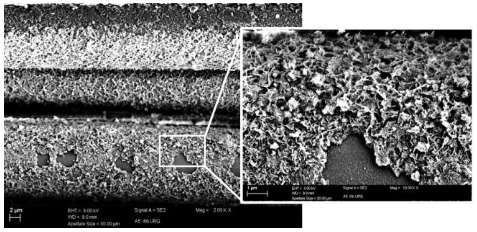
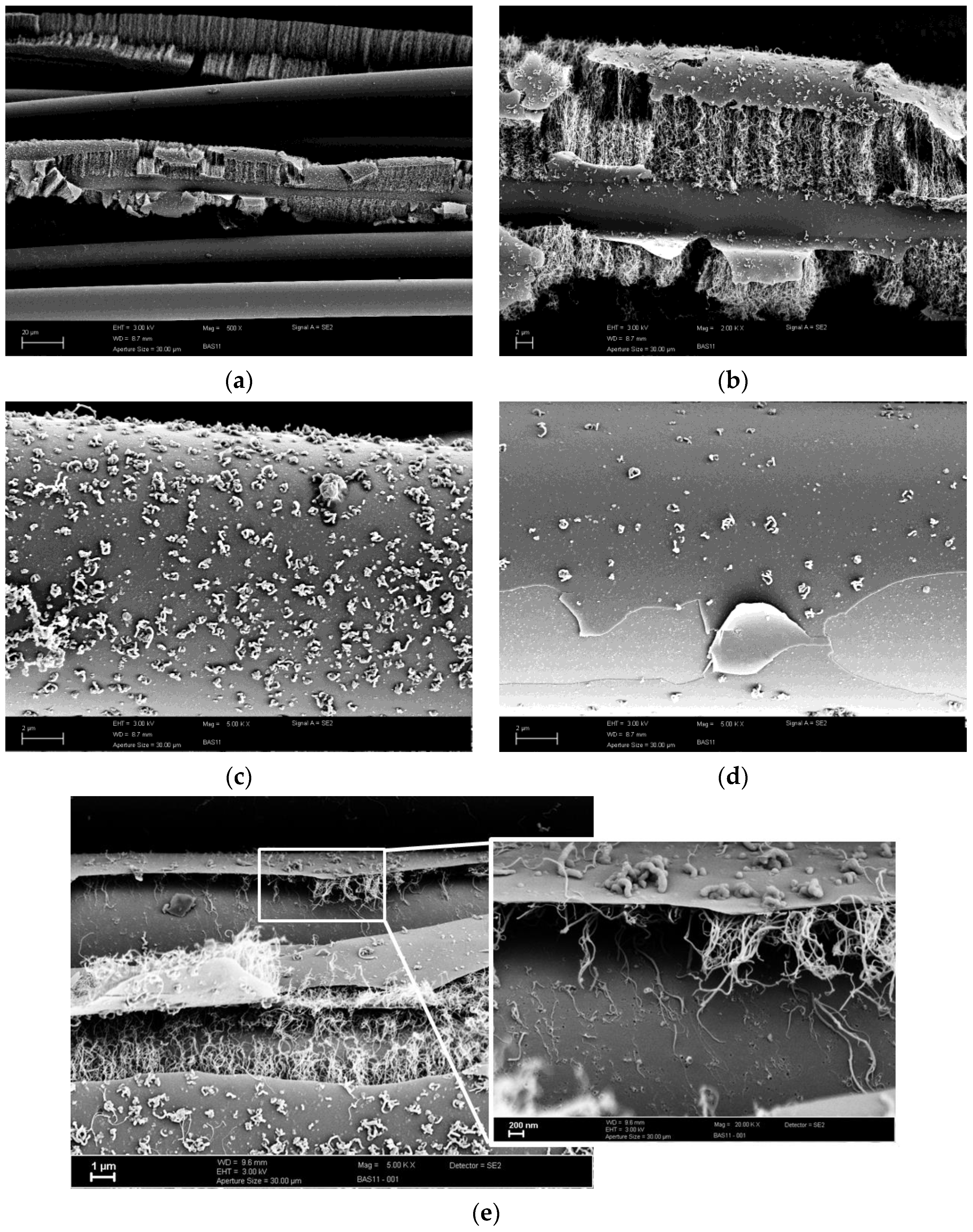
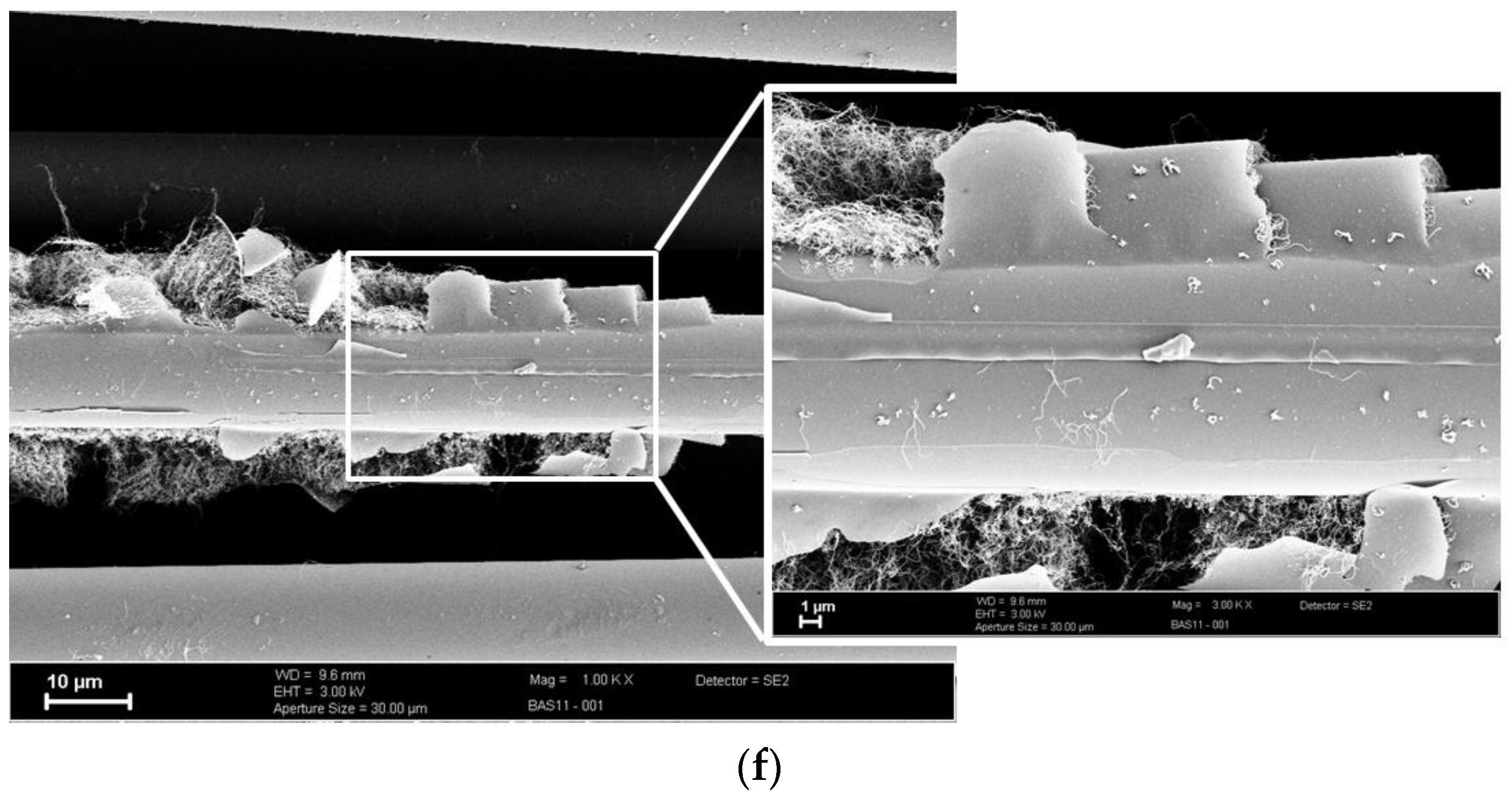
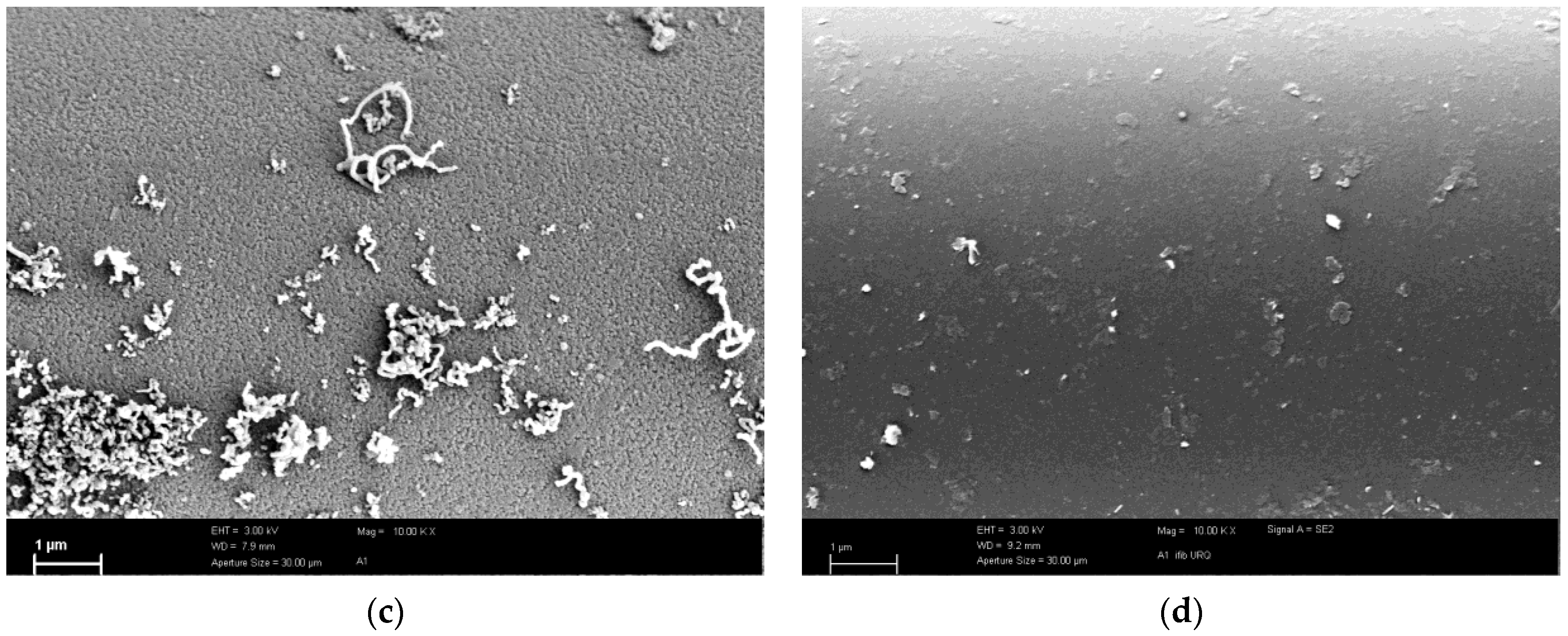
3.2. CNT Growth onto Basalt Fibers after CVD Treatment at 800 °C and at 700 °C

SEM investigations reveal that the initial BAS11and NaOH-treated BAS16(A5) fibers are able to initiate CNT growth by CVD treatments. Figure 3 shows several SEM images of the CVD treated BAS11 fibers. As can be seen, we found vertically aligned CNT carpets, isotropically distributed CNTs, as well as fibers with no or infrequent CNTs. The fibers seem to be covered with a thin coating (Figure 3d). From the shape of the C 1s high-resolution XPS spectrum (Figure 2c), it can be concluded that the coating layer consists of graphite-like bonded carbon atoms (sp2 state). Interestingly, it looks like these carboneous coating layers are crucial for the formation and growing of aligned CNT carpets. Considered with a higher magnification, Figure 3b–f, it is obvious that the top of the layer is settled randomly with small, more curved CNTs, whereas more elongated CNTs are located underneath. Probably, the CNTs bridge the detached layer and the fiber surface. The thickness of the aligned CNT array is in the range from a few nm up to approximately 20 nm. In particular, Figure 3f indicates that local ongoing CNT growth breaks the formed surface coating. Currently, it is not clear if the CNTs grow from top to bottom or vice versa.
In the experiment designated as CVD03, the temperature during stage V, the CNT-growing phase, was reduced to 700 °C in order to retain sufficient tensile strength and/or avoid major drops in fiber tensile strength. After CVD03 treatment, the average tensile strength is reduced by about 32%–40% (Table 4). However, the surface of the BAS11 fibers initiated CNT growth as well as the BAS16(A5) fiber (Figure 4). We didn’t observe any CNT carpets. On the CVD03 treated BAS11 fiber we found infrequent CNTs in balled or elongated shapes (Figure 4a), whereas the corrosion shell of the NaOH treated fiber BAS16(A5) is more intensely overgrown by CNTs. Partly, we found elongated CNTs with a length of a few µm bridging the interspace between two fibers (Figure 4b). The strength properties are significantly reduced by the alkali and subsequent CVD treatments. Thus, it was impossible to perform single fiber tensile tests.

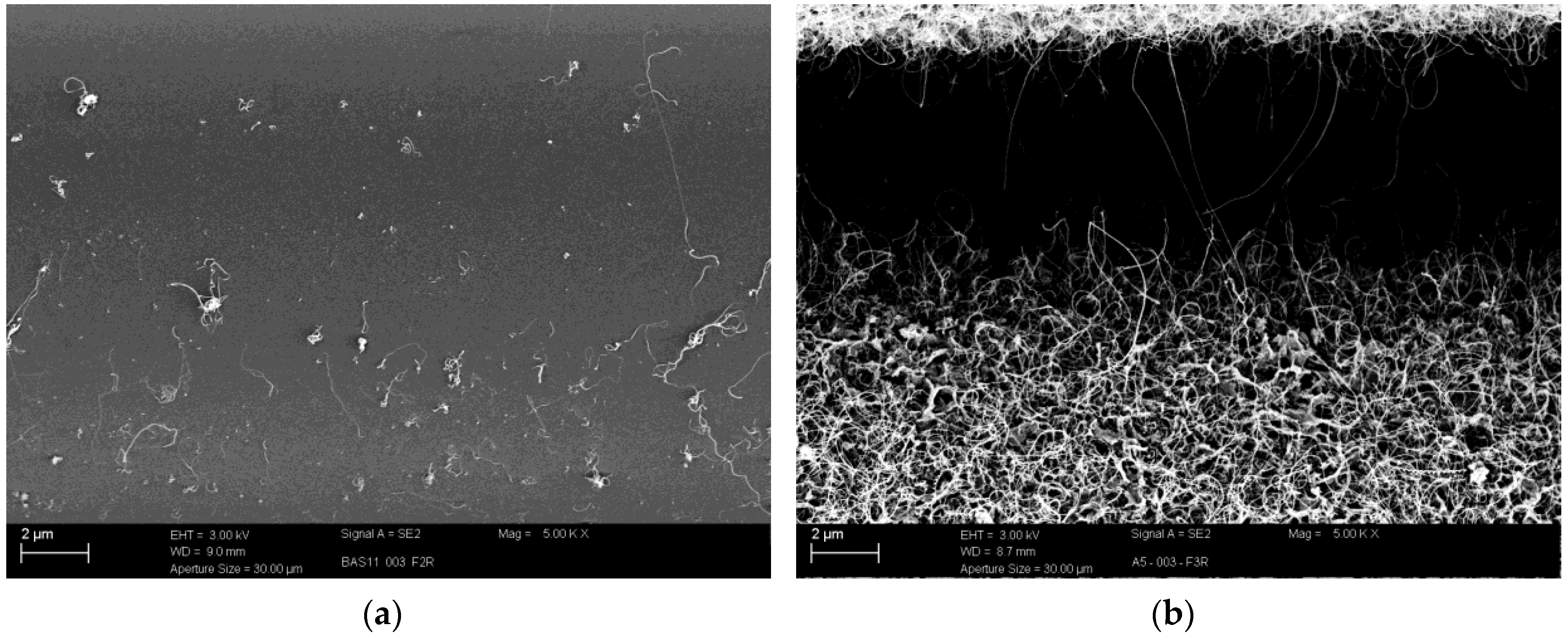
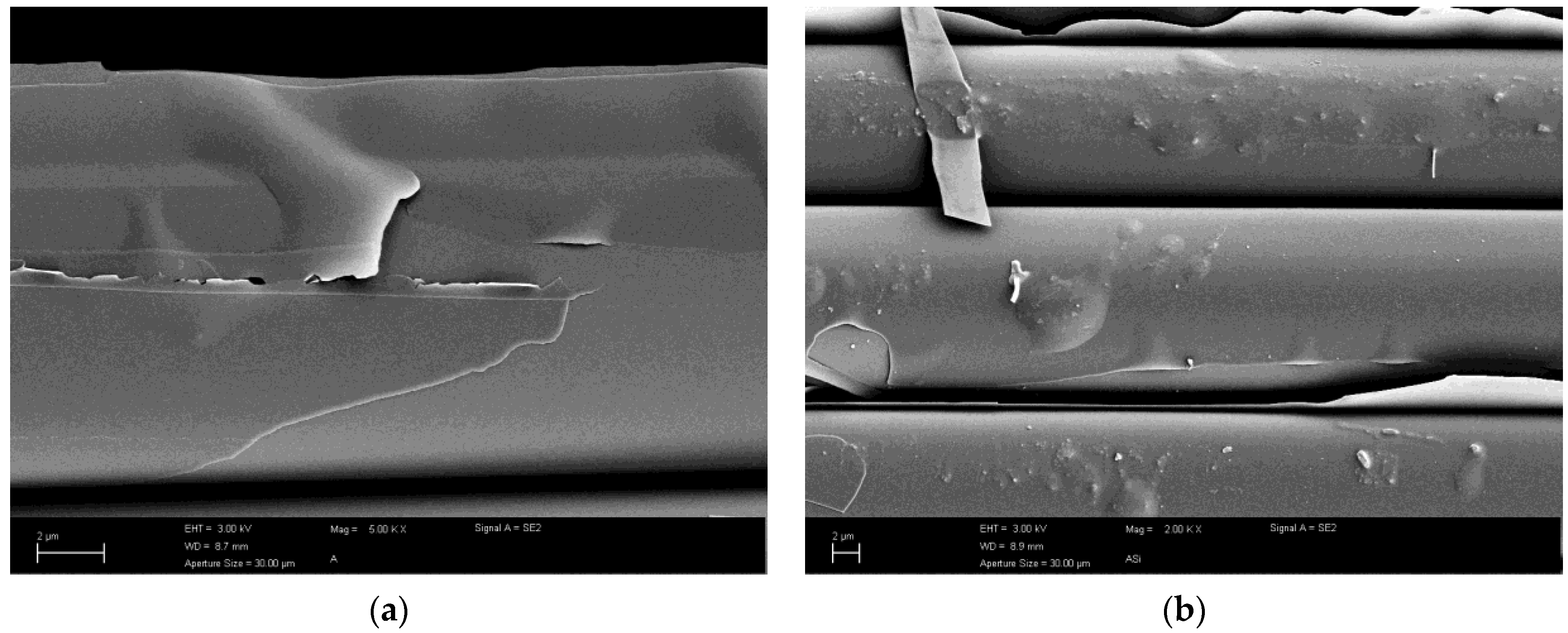
3.3. CVD Treated Fiber Surfaces without C2H2 Flow

In order to study the surfaces of the basalt fiber samples before the sp2 carbon-containing layer was formed, the CVD experiment was carried out with a mixture of H2 and Ar process gas (CVD02). As expected, the decrease of the relative carbon content showed that the H2 treatment purified the fiber surfaces by a partial removal of the surface contamination layer. Therefore, the contents of the elements of the basalt’s aluminosilicate phase (aluminum and silicon) and the embedded ions of sodium and potassium seemed to be increased (Table 3). However, iron was not analyzed in H2-treated surfaces. These findings seemed to be interesting because it is known that iron is a potential catalyst supporting the CNT growth. Due to the absence of iron it can be concluded that traces of other metal ions, for example, titanium or aluminum ions, contribute to the CNT formation. In summary, the initiation of growth and the formation mechanism of the CNT layers are not fully understood.
Two distinctive surface topographies were detected by AFM: on the one hand, a very fine needle-like structure with low height, on the other hand, a coarser surface with more plate-like or globular structures was observed (Figure 5). Both samples BAS11 and BAS16(A) (not shown here) show these characteristic surfaces after the CVD02 treatment. The fine and coarse textures are highlighted in the phase images (Figure 5c,d). Thereby, some of the “needle-caps” cause a stronger phase shift.
The AFM investigations do not give a distinct indication about growth stimuli. We assume the needle-like surface could be more effective. Here, a systematic monitoring of pre-selected fine and coarse structured single fibers is needed to substantiate the assertion.

3.4. Alkali Attacked Surfaces and Initial Sized Surface

The SEM investigations reveal that both BAS16(A-Si) and BAS16(A) are not catalysts for CNT growth. There were no indications for grown CNTs after the CVD01 treatment. Both fibers were covered by a layer that appeared less adhesive (Figure 6a,b). However, we already demonstrated that fiber BAS16 becomes effective by a NaOH attack. As shown in Figure 4b, the corrosion shell formed after a 5 h NaOH treatment at a temperature of 80 °C induces CNT growth. Beside the 5 h alkali attack, we reduced the immersion time to 1 h. We found just a few CNTs had grown on the fiber surface after the CVD01 treatment (Figure 6c). Consequently, we conclude that a surface which is only a little roughened and/or changed in the surficial composition is not sufficient for homogenous CNT coverage. Here, further ageing experiments varied in time and temperature are necessary in order to evaluate a beneficial pre-treatment. Moreover, these experiments should be examined in view of its success to remove the initial sizing.

5. Conclusions

In summary, we carried out CVD experiments and investigated the basalt fibers BAS11 and BAS16, supplied by two different manufactures, in regard to their capability to be self-catalyzing for CNT growth. Thereby, we observed that BAS11 stimulates the CNT growth, but BAS16(A) does not. Neither XPS nor AFM investigations have given key indications about the original cause. We demonstrated by means of BAS16 that a corrosion shell formed by an NaOH pre-treatment has a growth stimulating effect. However, the tensile strength is reduced considerably.
Direct growth of CNTs onto fibers by using the CVD process has been studied many times, but many aspects are understood incompletely because CNT growth is a very complex process, both the properties of the substrate used and the CVD process parameters may affect growth success. Sometimes it is claimed that the catalytic effect is more dependent on the particle size of a catalyst and/or the roughness of a surface than on the chemical composition of the material [18,20]. An interesting assumption is proposed by Huang et al. [20] that structural defects might support the decomposition of hydrocarbon molecules and, in case of nanoparticles are used as catalysts, the high curvatures of nanoparticles promote the formation of graphitic structures inducing further CNT growth. BAS11 tends to result in lower single fiber strength values after the CVD02 treatment: this might be a clue for a more disordered surface. This assumption has to be confirmed by further experiments, for example, by screening defined damaged fibers. This paper should be considered as a first communication of the growing of CNT on commercially available basalt fibers without using a catalyst solution. The mechanism of CNT formation and growth is not fully understood at this time, and conditions supporting the CNT formation must be studied in further works. If we get more insights about the surface chemistry of basalt fibers and the—probably catalysis—of CNT formation and growth, we will publish the results in future.
The capability to stimulate CNT growth is a very exciting feature which could open totally new application fields for basalt fibers if the mechanism behind it is more understood. Focusing recycling strategies, sizing burn-off, and subsequent formation of “nano-rough surfaces” should be studied in more detail. If it would be successful, the loss in mechanical strength could be revalued by the implementation of new functionalities.

Acknowledgments

The authors are indebted to Matthias Krüger and Steffi Preßler (Leibniz-Institut für Polymerforschung Dresden e.V.) for experimental assistance and helpful discussions. This work was partly funded by the German Academic Exchange Service (Programmes for Project-Related Personal Exchange (PPP) China, Grant No. 57137844) and the China-Germany Scientific Cooperation Program (Programmes for Project-Related Personal Exchange (PPP), Grant No. 2014-6065).

Author Contributions

Theresa Förster and Bin Hao conceived and designed the experiments; Bin Hao and Enrico Wölfel performed the experiments; Frank Simon analyzed the XPS data; Peng-Cheng Ma contributed the scientific discussions. Theresa Förster, Edith Mäder, and Frank Simon wrote the paper.

Conflicts of Interest

The authors declare no conflict of interests.

References

  1. Thomason, J.L.; Yang, L.; Meier, R. The properties of glass fibres after conditioning at composite recycling temperatures. Compos. A Appl. Sci. Manuf. 2014, 61, 201–208. [Google Scholar] [CrossRef]
  2. Yang, L.; Sáez, E.R.; Nagel, U.; Thomason, J.L. Can thermally degraded glass fibre be regenerated for closed-loop recycling of thermosetting composites? Compos. A Appl. Sci. Manuf. 2015, 72, 167–174. [Google Scholar] [CrossRef]
  3. Förster, T.; Mäder, E. Defect healing efficiency of fibre sizings. To be submitted.
  4. Maples, H.A.; Wakefield, S.; Robinson, P.; Bismarck, A. High performance carbon fibre reinforced epoxy composites with controllable stiffness. Compos. Sci. Technol. 2014, 105, 134–143. [Google Scholar] [CrossRef]
  5. Bismarck, A.; Blaker, J.; Anthony, D.; Qian, H.; Maples, H.; Robinson, P.; Shaffer, M.; Greenhalgh, E. Development of novel composites through fibre and interface/interphase modification. IOP Conf. Ser. Mater. Sci. Eng. 2016, 139, 12001. [Google Scholar] [CrossRef]
  6. Zhang, J.; Liu, J.; Zhuang, R.; Mäder, E.; Heinrich, G.; Gao, S. Single MWNT-Glass Fiber as Strain Sensor and Switch. Adv. Mater. 2011, 23, 3392–3397. [Google Scholar] [CrossRef] [PubMed]
  7. Gao, S.; Zhuang, R.-C.; Zhang, J.; Liu, J.-W.; Mäder, E. Glass Fibers with Carbon Nanotube Networks as Multifunctional Sensors. Adv. Funct. Mater. 2010, 20, 1885–1893. [Google Scholar] [CrossRef]
  8. Zhang, J.; Zhuang, R.; Liu, J.; Mäder, E.; Heinrich, G.; Gao, S. Functional interphases with multi-walled carbon nanotubes in glass fibre/epoxy composites. Carbon 2010, 48, 2273–2281. [Google Scholar] [CrossRef]
  9. Bekyarova, E.; Thostenson, E.T.; Yu, A.; Kim, H.; Gao, J.; Tang, J.; Hahn, H.T.; Chou, T.-W.; Itkis, M.E.; Haddon, R.C. Multiscale carbon nanotube-carbon fiber reinforcement for advanced epoxy composites. Langmuir 2007, 23, 3970–3974. [Google Scholar] [CrossRef] [PubMed]
  10. Kim, M.T.; Rhee, K.Y.; Lee, J.H.; Hui, D.; Lau, A.K.T. Property enhancement of a carbon fiber/epoxy composite by using carbon nanotubes. Compos. B Eng. 2011, 42, 1257–1261. [Google Scholar] [CrossRef]
  11. Lee, J.H.; Rhee, K.Y.; Park, S.J. The tensile and thermal properties of modified CNT-reinforced basalt/epoxy composites. Mater. Sci. Eng. A 2010, 527, 6838–6843. [Google Scholar] [CrossRef]
  12. Kim, M.T.; Rhee, K.Y.; Park, S.J.; Hui, D. Effects of silane-modified carbon nanotubes on flexural and fracture behaviors of carbon nanotube-modified epoxy/basalt composites. Compos. B Eng. 2012, 43, 2298–2302. [Google Scholar] [CrossRef]
  13. Lee, S.-O.; Choi, S.-H.; Kwon, S.H.; Rhee, K.-Y.; Park, S.-J. Modification of surface functionality of multi-walled carbon nanotubes on fracture toughness of basalt fiber-reinforced composites. Compos. B Eng. 2015, 79, 47–52. [Google Scholar] [CrossRef]
  14. Teo, K.B.; Singh, C.; Chhowalla, M.; Milne, W.I. Catalytic synthesis of carbon nanotubes and nanofibers. Encycl. Nanosci. Nanotechnol. 2003, 10, 1–22. [Google Scholar]
  15. Yan, Y.; Miao, J.; Yang, Z.; Xiao, F.-X.; Yang, H.B.; Liu, B.; Yang, Y. Carbon nanotube catalysts: Recent advances in synthesis, characterization and applications. Chem. Soc. Rev. 2015, 44, 3295–3346. [Google Scholar] [CrossRef] [PubMed]
  16. Tripathi, N.; Mishra, P.; Joshi, B.; Islam, S.S. Precise control over physical characteristics of Carbon Nanotubes by differential variation of Argon flow rate during Chemical Vapor Deposition processing: A systematic study on growth kinetics. Mater. Sci. Semicond. Process. 2015, 35, 207–215. [Google Scholar] [CrossRef]
  17. De Greef, N.; Zhang, L.; Magrez, A.; Forró, L.; Locquet, J.-P.; Verpoest, I.; Seo, J.W. Direct growth of carbon nanotubes on carbon fibers: Effect of the CVD parameters on the degradation of mechanical properties of carbon fibers. Diam. Relat. Mater. 2015, 51, 39–48. [Google Scholar] [CrossRef]
  18. Tripathi, N.; Mishra, P.; Joshi, B.; Harsh; Islam, S.S. Catalyst free, excellent quality and narrow diameter of CNT growth on Al2O3 by a thermal CVD technique. Physica E 2014, 62, 43–47. [Google Scholar] [CrossRef]
  19. Li, R.; Lachman, N.; Florin, P.; Wagner, H.D.; Wardle, B.L. Hierarchical carbon nanotube carbon fiber unidirectional composites with preserved tensile and interfacial properties. Compos. Sci. Technol. 2015, 117, 139–145. [Google Scholar] [CrossRef]
  20. Huang, S.; Cai, Q.; Chen, J.; Qian, Y.; Zhang, L. Metal-catalyst-free growth of single-walled carbon nanotubes on substrates. J. Am. Chem. Soc. 2009, 131, 2094–2095. [Google Scholar] [CrossRef] [PubMed]
  21. Shah, K.A.; Tali, B.A. Synthesis of carbon nanotubes by catalytic chemical vapour deposition: A review on carbon sources, catalysts and substrates. Mater. Sci. Semicond. Process. 2016, 41, 67–82. [Google Scholar] [CrossRef]
  22. Rahaman, A.; Kar, K.K. Carbon nanomaterials grown on E-glass fibers and their application in composite. Compos. Sci. Technol. 2014, 101, 1–10. [Google Scholar] [CrossRef]
  23. Wood, C.D.; Palmeri, M.J.; Putz, K.W.; Ho, G.; Barto, R.; Brinson, L.C. Nanoscale structure and local mechanical properties of fiber-reinforced composites containing MWCNT-grafted hybrid glass fibers. Compos. Sci. Technol. 2012, 72, 1705–1710. [Google Scholar] [CrossRef]
  24. Karger-Kocsis, J.; Mahmood, H.; Pegoretti, A. Recent advances in fiber/matrix interphase engineering for polymer composites. Prog. Mater. Sci. 2015, 73, 1–43. [Google Scholar] [CrossRef] [Green Version]
  25. Förster, T.; Mäder, E.; Jesson, D.A.; Watts, J.F. Surface analyses of basalt fibres: Tailoring the interphase of “green” fibre reinforced composites. In Proceedings of the 19th International Conference on Composite Materials (ICCM19), Montreal, QC, Canada, 28 July–2 August 2013.
  26. Smedskjaer, M.M.; Yue, Y.; Deubener, J.; Gunnlaugsson, H.P.; Mørup, S. Modifying glass surfaces via internal diffusion. J. Non-Cryst. Solids 2010, 356, 290–298. [Google Scholar] [CrossRef]
  27. Smedskjaer, M.M.; Yue, Y.; Deubener, J.; Mørup, S. Impact of cationic diffusion on properties of iron-bearing glass fibres. Phys. Chem. Glas. J. Glasses Sci. Technol. B 2010, 51, 271–280. [Google Scholar]
  28. Smedskjaer, M.M.; Yue, Y.Z. Inward cationic diffusion in glass. J. Non-Cryst. Solids 2009, 355, 908–912. [Google Scholar] [CrossRef]
  29. Yue, Y.; Korsgaard, M.; Kirkegaard, L.F.; Heide, G. Formation of a Nanocrystalline Layer on the Surface of Stone Wool Fibers. J. Am. Ceram. Soc. 2009, 92, 62–67. [Google Scholar] [CrossRef]
  30. Förster, T.; Plonka, R.; Scheffler, C.; Mäder, E.; Brameshuber, W. Challenges for fibre and interphase design of basalt fibre reinforced concrete. In International RILEM Conference on Material Science; RILEM Publications SARL: Bagneux, France, 2010; pp. 57–66. [Google Scholar]
  31. Förster, T.; Sommer, G.S.; Mäder, E.; Scheffler, C. Surface, interphase and tensile properties of unsized, sized and heat treated basalt fibres. IOP Conf. Ser. Mater. Sci. Eng. 2016, 139, 12019. [Google Scholar] [CrossRef]
  32. Rybin, V.A.; Utkin, А.V.; Baklanova, N.I. Corrosion of uncoated and oxide-coated basalt fibre in different alkaline media. Corros. Sci. 2016, 102, 503–509. [Google Scholar] [CrossRef]
  33. Novais, R.M.; Simon, F.; Paiva, M.C.; Covas, J.A. The influence of carbon nanotube functionalization route on the efficiency of dispersion in polypropylene by twin-screw extrusion. Compos. Appl. Sci. Manuf. 2012, 43, 2189–2198. [Google Scholar] [CrossRef]
Figure 1. SEM images of the surface of the NaOH treated basalt fiber BAS16(A5).
Fibers 04 00028 g001
Figure 2. High-resolution C 1s XPS spectra recorded from samples BAS16(A) initial (a); BAS16(A-Si) (b); BAS11 CVD01 treated (c); and BAS16(A) CVD01 treated (d). Sample BAS16(A) initial contained a small amount of potassium, which was identified by the K 2p3/2 and K 2p1/2 peaks.
Fibers 04 00028 g002
Figure 3. Surface of basalt fiber BAS11 after CVD treatment at a temperature of 800 °C (CVD01); Magnifications and scale bars: (a) 500×/20 µm; (b) 2000×/2 µm; (c,d) 5000×/2 µm; (e) 3000×/1 µm and 20,000×/200 nm; (f) 1000×/10 µm and 3000×/1 µm.
Fibers 04 00028 g003aFibers 04 00028 g003b
Figure 4. Surface of basalt fibers after CVD treatment at a temperature of 700 °C (CVD03): BAS11 (a) and BAS16(A5)–NaOH treated (b). Magnifications and scale bars: 5000×/2 µm.
Fibers 04 00028 g004
Figure 5. Topography (a,c) and phase images (b,d) of CVD02 treated BAS11 (roughness parameters (a) Rmax (2 × 2 µm) = 9.7 nm; Ra (2 × 2 µm) = 0.48 nm; (c) Rmax (2 × 2 µm) = 21.2 nm; Ra (2 × 2 µm) = 2.13 nm).
Fibers 04 00028 g005aFibers 04 00028 g005b
Figure 6. SEM images of the surface of BAS16(A): (a) CVD01 treated but without prior NaOH treatment; (b) CVD01 treated but initially sized fiber; (c) 1 h NaOH treated and subsequent CVD01 treated; and (d) 1 h NaOH treated without CVD01 treatment. Magnifications and scale bars: (a) 5000×/2 µm; (b) 2000×/2 µm; and (c,d) 10,000×/1 µm.
Fibers 04 00028 g006aFibers 04 00028 g006b
Table 1. Investigated basalt fibers.
FiberBAS11BAS16(A)BAS16(A1)BAS16(A5)BAS16(A-Si)
Sizingnonononoyes
Alkali treatmentnono1 h5 hno
Table 2. Overview of chemical vapor deposition (CVD) treatments and conditions used (AT = ambient temperature, Ti = 700 °C or 800 °C).
StageTemperature (°C)Time (min)GasesFlow Rate (sccm)
IAT to 300 °C30Ar200
II300 to Ti50Ar+H2200/14
IIITi30Ar+H2200/14
IVTi30Ar+H2+C2H2200/14/37
VTi to 700 °C-Ar200
VI700 °C to AT-Ar<200
Table 3. Relative elementary surface composition of the initial fiber samples determined from the wide-scan XPS spectra.
Elemental RatioBAS11 InitialBAS11 CVD02BAS16(A) InitialBAS16(A) CVD02BAS16(A5) NaOH Treated
(C):(O)0.850.670.640.330.37
(Na):(O)0.020.050.020.040.03
(Mg):(O)0.01-0.03-0.01
(Al):(O)0.100.130.120.140.05
(Si):(O)0.350.400.320.390.29
(K):(O)-0.030.010.03-
(Ca):(O)0.020.01traces0.020.07
(Ti):(O)traces0.01tracestracestraces
(Mn):(O)traces----
(Fe):(O)0.01-0.03-0.02
(C):(Si)2.421.682.000.851.28
Table 4. Average single fiber tensile strength before the CVD treatment (σm), the residual tensile strength after the CVD treatment (σm, residual), and based on Weibull analysis: the characteristic strength σ0, the Weibull modulus m, and the coefficient of determination R (Linear regression).
FiberCVDSingle Fiber Tensile Test
TiCarbon SourceCNTσmσ0mRσm, residual
(°C) (MPa)(MPa)(-)(-)(%)
BAS11–initialnonono1698 ± 71819322.30.96
BAS11–CVD02800nono863 ± 1579276.50.9851
BAS11–CVD03700C2H2yes1023 ± 27611234.30.9960
BAS16(A)–initialnonono1762 ± 59419733.20.98
BAS16(A)–CVD02800nono1034 ± 21611156.00.8959
BAS16(A)–CVD03700C2H2no1190 ± 37513154.00.8768

