Article

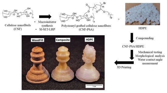
Production and 3D Printing of a Nanocellulose-Based Composite Filament Composed of Polymer-Modified Cellulose Nanofibrils and High-Density Polyethylene (HDPE) for the Fabrication of 3D Complex Shapes

by
Feras Dalloul
,
Jakob Benedikt Mietner
and
Julien R. G. Navarro
*
Institute of Wood Science, Universität Hamburg, 21031 Hamburg, Germany
*
Author to whom correspondence should be addressed.
Fibers 2022, 10(10), 91; https://doi.org/10.3390/fib10100091
Submission received: 26 September 2022 / Revised: 14 October 2022 / Accepted: 18 October 2022 / Published: 21 October 2022
(This article belongs to the Topic Cellulose and Cellulose Derivatives)

Abstract

:
This work aims to produce a 3D-printable bio-based filament composed of high-density polyethylene (HDPE) and chemically modified cellulose nanofibrils. Printing using HDPE as a raw material is challenging due to its massive shrinkage and warping problems. This paper presents a new method to overcome those difficulties by enhancing the mechanical properties and achieving better print quality. This was achieved using modified cellulose nanofibrils (CNFs) as fillers. Firstly, CNF was converted to a CNF-based macroinitiator through an esterification reaction, followed by a surface-initiated single-electron transfer living radical polymerization (SI-SET-LRP) of the hydrophobic monomer stearyl acrylate. Poly stearyl acrylate-grafted cellulose nanofibrils, CNF-PSAs, were synthesized, purified and characterized with ATR-FTIR, 13C CP-MAS NMR, FE-SEM and water contact angle measurements. A composite was successfully produced using a twin-screw extruder with a CNF-PSA content of 10 wt.%. Mechanical tests were carried out with tensile testing. An increase in the mechanical properties, up to 23% for the Young’s modulus, was observed. A morphologic analysis also revealed the good matrix/CNF compatibility, as no CNF aggregates could be observed. A reduction in the warping behavior for the composite filament compared to HDPE was assessed using a circular arc method. The 3D printing of complex objects using the CNF-PSA/HDPE filament resulted in better print quality when compared to the object printed with neat HDPE. Therefore, it could be concluded that CNF-PSA was a suitable filler for the reinforcement of HDPE, thus, rendering it suitable for 3D printing.

Graphical Abstract

1. Introduction

Academic and public interest in additive manufacturing (AM), also known as 3D printing, has been growing rapidly during the last decade [1,2,3]. Fused-filament fabrication or fused deposition modeling (FDM) is a 3D-printing technology, which uses a continuous filament as the starting 3D ink material. The FDM process and the construction/building-up of complex 3D-printed objects are based on the layer-by-layer deposition process of a thermoplastic material (filament) extruded through a heated nozzle [4,5]. FDM is an efficient approach for the production of components and objects with complex geometries that are hardly achievable with traditional subtractive machining methods. As a result, 3D objects can be produced relatively rapidly and at a lower cost while using less material, thus, minimizing industrial waste [6,7,8,9].
Nowadays, numerous 3D-printable filaments, mainly composed of amorphous polymers, are commercially available. The most commonly used filaments are acrylonitrile butadiene styrene (ABS) [10], polylactic acid (PLA) [11], high-impact polystyrene (HIPS) [12] and polycarbonate (PC) [13]. This popularity can be explained by the fact that they are nontoxic, exhibit good printability and are available in a wide range of colors with good durability of the printed object.
In contrast, 3D filaments composed of semicrystallized polymers are harder to process due to shrinkage and warpage of the final 3D-printed object after cooling [14], which leads to unsuccessful prints or poorer quality products. A good example of these polymers’ kind is high-density polyethylene (HDPE). HDPE is a semicrystalline polymer and one of the most widely manufactured polymers worldwide. Its potential conversion (or waste reconversion) into a 3D-printable material is crucial for the environment as it would improve significantly its recycling availability, and lower the carbon footprint [15,16]. However, HDPE is a challenging material to print as it crystallizes rapidly upon cooling, leading to a decrease in the object dimension, e.g., shrinkage [17]. Moreover, the low surface energy often results in poor layer–layer adhesion, e.g., layer separation, which when combined with the first layer–print bed (e.g., build surface) adhesion difficulty, automatically leads to warping out of the printing plane [18]. Gudadhe et al. [19] successfully 3D printed numerous objects composed of recycled HDPE through the incorporation of additives in the HDPE formulation. The use of dimethyl dibenzylidene sorbitol (DMDBS) and linear low-density polyethylene (LDPE) as additives allowed to improve the layer adhesion but also avoid warpage-related issues.
Mora et al. [20] reported that the incorporation of carbon nanotubes (CNTs) in the HDPE formulation provided considerable improvements in the printing process while also increasing the final mechanical properties. It can be noted that the mechanical properties of the composite can be improved by adding a filler, a reinforcing agent, to reduce those undesired and unwanted effects (shrinkage and warpage). These modifications lead to better object printability and shape fidelity as already reported elsewhere [21,22]. In contrast to those synthetic fillers, numerous efforts have been made to use natural fibers as reinforcing agents for polymers to address the environmental challenges and offer a greener alternative. Cellulose nanofibrils (CNFs) are among the candidates extensively used to produce lightweight composites with excellent mechanical properties [23,24,25,26,27]. CNF is attractive for its nontoxicity, biodegradability, biological availability and rigidity [28,29].
The main challenge to overcome with a bio-based (nano)composite is the correct adhesion between the filler/reinforcing agent and the host matrix [30]. CNF has an abundant number of hydroxyl groups on its surface, conferring its hydrophilic character, while most thermoplastic polymers are nonpolar and have a hydrophobic matrix. This ultimately results in poor interfacial compatibility between the two components, with a large aggregation of the fibers in the host matrix. To overcome this issue, it is mandatory to decrease the fibril hydrophilicity through chemical surface modification of the nanocellulose [31,32,33,34,35,36].
This work aimed to investigate the potential ability of a polymer-modified CNF to drastically increase the 3D printability of a HDPE bio-based composite through fused deposition modeling (FDM). After careful extraction and a solvent exchange to dimethyl sulfoxide (DMSO), the CNF was converted into a CNF-based macroinitiator, followed by a surface-initiated single-electron transfer living radical polymerization (SI-SET-LRP) of the stearyl acrylate monomer. The purpose of this polymerization reaction was to modify the overall surface polarity and, therefore, improve the compatibility with the hydrophobic HDPE. All these reactions were characterized with ATR-FTIR, CP/MAS 13C-NMR spectroscopy, ultra-high-resolution field emission scanning electron microscopy (FE-SEM) and contact angle measurements. Finally, the poly(stearyl acrylate)-grafted CNF was compounded with HDPE and extruded to produce a 3D-printable filament. This extruded filament was also used to produce standard specimens for mechanical testing through injection molding; therefore, the mechanical properties were evaluated. The effectiveness and compatibility of the composite could also be monitored with scanning electron microscopy (SEM) and analysis of the broken specimen. Finally, its suitability as a 3D-printing filament, its deformation/warping reduction and the shape fidelity of the printed object were studied and compared to pure HDPE and Woodfill (PLA/PHA fine pinewood fibers).

2. Materials and Methods

2.1. Materials

Imidazole (≥99%), dimethyl sulfoxide (DMSO, ≥99%), tris[2-(dimethylamino)ethyl]amine (Me6TREN, 97%), isopropanol, toluene and Cu wire (diameter 1 mm) were purchased from Alfa Aesar. 2-bromo-2-methylpropionate (98%), ethyl 2-bromo-2-methylpropionate (98%) and stearyl acrylate (SA, 97%) were purchased from Sigma-Aldrich. High-density polyethylene was obtained from SABIC (HDPE CC3054). For cellulose nanofibril (CNF) production, a dried elemental chlorine-free (ECF) bleached softwood kraft pulp was obtained from MERCER Stendal GmbH, Germany. The kraft pulp was composed from pine (30–60%) and spruce (40–70%), PFI-milled at 23 °C and 50% of relative humidity. Ultrapure Milli-Q water was used for the solvent exchange procedure. Woodfill (PLA/PHA + fine pinewood fibers) filament was obtained from ColorFabb, Belfeld, The Netherlands.

2.2. Materials Synthesis

2.2.1. Preparation of Cellulose Nanofibrils from Kraft Pulp

An amount of 10 g of dry pulp was shredded and ground using a Herzog grinding machine to achieve a high degree of grinding. The milling vessel was set in the vibrating mill and ground with a certain amount of 215 mL of distilled water for 6 min at 6000 rpm. To determine the grinding rate, the suspension was diluted to 0.24 wt.% and measured using a Schopper–Riegler measuring vessel. The degree of grinding was 92° SR. Then, the suspension was passed through a microfluidizer (MicrofluidicsTM M-100EH-30). This process was completed in two steps, firstly the suspension was passed twice through two thin chambers with orifice widths of 400 µm and 200 µm under 15,000 Psi, and then six times through two thinner chambers of 200 µm and 100 µm under 25,000 Psi. The CNF suspension was then concentrated through centrifugation (SorvallTM LYNXTM 6000 Superspeed centrifuge, Thermo Scientific, Shanghai, China) at 5500 rpm for 45 min.

2.2.2. Solvent Exchange Process

The gel-like CNF (20.4 g, 2.36 wt.%) was firstly mixed with 80 mL of distilled water and stirred for 30 min. DMSO (150 mL) was then added dropwise while maintaining vigorous stirring of the suspension. The obtained CNF/H2O/DMSO suspension was concentrated using centrifugation (12,000 rpm, 20 min). The supernatant was discarded and replaced with fresh DMSO. This process was repeated four times and resulted in a 1.8 wt.% DMSO-based gel.

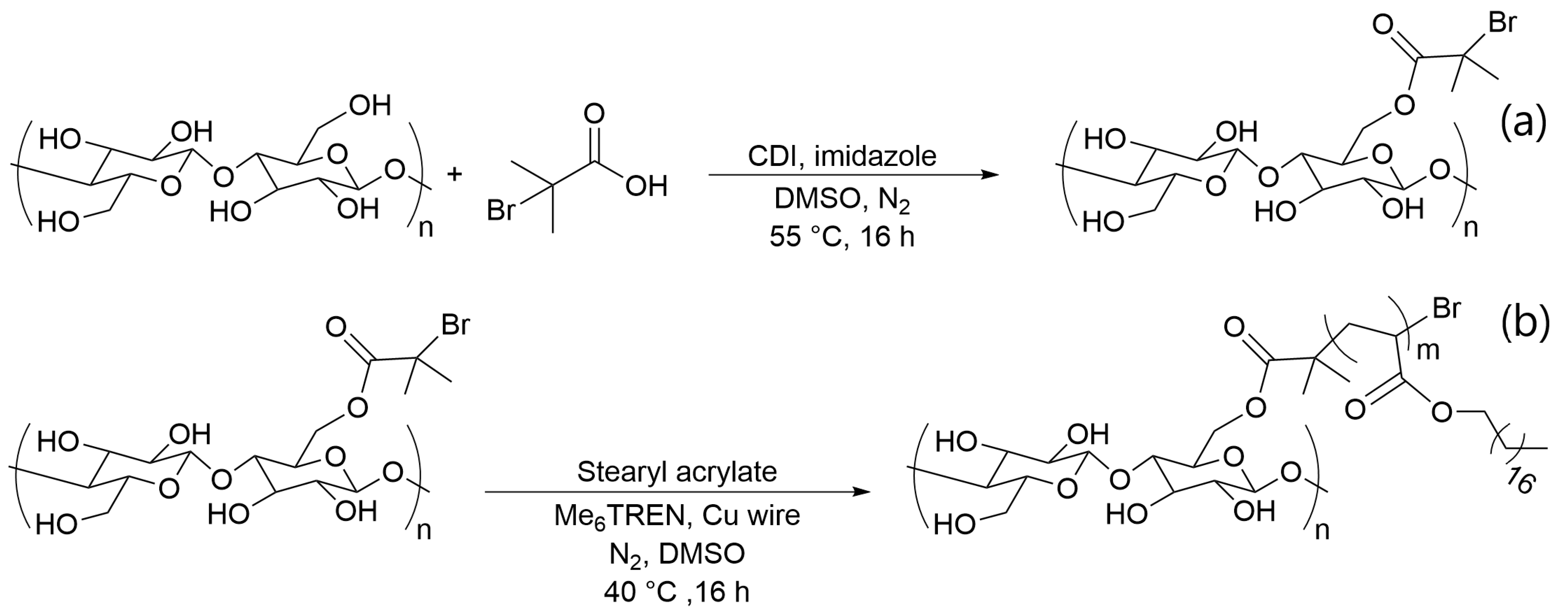
2.2.3. Preparation of CNF Macroinitiators by Esterification

The macroinitiator was prepared following the same procedure previously reported [37]. From this procedure, a total of 16.7 g of gel (2.1 wt.%) was obtained.

2.2.4. Grafting of Stearyl Acrylate onto CNF (CNF-PSA) Using SET-LRP

A copper wire (length = 50 cm) was first activated by soaking it in concentrated hydrochloric acid for approximately 10 min. After that, the wire was rinsed with water then acetone and finally dried. In a three-neck flask, 15.3 g (2.1 wt.%) of the CNF macroinitiator was dispersed in 240 mL of DMSO. In the meantime, the monomer SA (40 g) dissolved in toluene (120 mL) was passed through an aluminum oxide plug (Al2O3 basic) to remove the inhibitor/stabilizer, and then immediately injected in the CNF suspension. The activated copper wire was then added to the mixture and the reaction flask was then degassed by nitrogen purging at 40 °C. Me6TREN (2 wt.% in DMSO) ligand was finally added and the reaction was allowed to proceed for 16 h at 40 °C under a nitrogen atmosphere. The suspension was then cooled down to room temperature. The CNF-PSA precipitate was collected, suspended in toluene and precipitated with isopropanol. The CNF-PSA was collected through centrifugation (4000 rpm, 10 min). This step was repeated 5 times. Finally, the CNF-PSA was suspended in toluene and the gel was concentrated through centrifugation (4000 rpm, 60 min). The resulting gel was finally dried under vacuum.

2.2.5. CNF Nanocomposite Preparation

A composite of HDPE with 10 wt.% poly(stearyl acrylate)-grafted cellulose nanofibrils (CNF-PSAs) was prepared. CNF-PSA was dried beforehand and chopped into small pellets. HDPE was also dried. Then, both components were mixed in the HAAKE™ MiniLab 3 microcompounder with counter-rotating screws at 150 °C and 100 rpm for 5 min for the first batch.

2.2.6. Filament Extrusion and 3D Printing

Filaments for 3D printing were produced using a HAAKE™ MiniLab 3 microcompounder. The components were loaded and compounded with counter-rotating screws, with a screw speed of 35 rpm at 150 °C. A caliper was used for controlling the filament size (1.75 mm) to ensure that the filament could be used on an Original Prusa i3 MK3S+ printer. The 3D-object STL file was obtained from Thingiverse [38] (creator: SteedMaker, license: CC BY-NC 4.0). The printing parameters were adjusted within the PrusaSlicer software (version 2.4.1). The nozzle temperature was set to 215 °C and the bed temperature to 60 °C. The nozzle diameter used was 0.4 mm and the printing speed was set to 20 mm/s, with a layer height of 0.2 mm. For the infill, a gyroïd pattern was chosen, with an infill percentage of 15%. In addition, for better adhesion, the object was printed on a HDPE sheet. The cooling fan was used starting from the 4th layer, at 50% of its capacity.

2.3. Material Characterization

ATR-FTIR (attenuated total reflection Fourier-transform infrared spectroscopy) was performed using a Bruker Vector 33 FTIR Fourier-transform infrared spectrometer I18500 PS15. Spectra were recorded with 64 scans in the spectral region of 4000–500 cm−1. The spectral resolution was 4 cm−1.
All samples’ CP/MAS 13C-NMR spectra were acquired on a Bruker 500 Avance III HD spectrometer at Larmor frequencies of 125 MHz and 500 MHz for 13C and 1H, respectively. These samples were placed into 4 mm zirconia rotors for magic angle spinning (MAS) at a rotation speed of 8 kHz. Creeping CP/MAS 13C-NMR spectra were recorded with a 13C mutation frequency of 50 kHz and a contact time of 1.5 ms. These spectra were acquired using Fourier transforms of the FIDs, and chemical shifts were referenced to pure tetramethylsilane (TMS).
For tensile testing, the nanocomposite was chopped into pellets and injection molded using a HAAKE™ Minijet II into test specimens for tensile testing with the cylinder temperature at 150 °C, mold temperature at 80 °C and pressure at 400 bar for 4 s. Specimens for tensile testing dimensions were 75 × 10 × 20 mm (according to the DIN EN ISO 527). In accordance with DIN EN ISO 527, the tensile test was performed using a Zwick-Roell universal testing machine with a load cell of 500 N and a ZWICK videoXtens video extensometer. The crosshead speed was 20 mm/min for the plain matrix and 1 mm/min for the composite. An initial load of 1 N was utilized to determine the properties. At minimum 5 and up to 12 specimens were tested, and the average values were obtained.
To measure the warping effect of HDPE and the composite, two 3D models were printed, both of which were flat rectangles. The first was fully filled and the second was hollow. The 3D patterns are presented in Scheme 1. Both models were printed using the same parameters described previously. The 3D prints were composed with various configurations, such as with/without LDPE tape and with/without enclosure. HDPE, composite and Woodfill were printed, placed side-by-side and pictured (Scheme 2). The warping of materials was measured using a circular arc method as illustrated in Scheme 1. Warped and bent materials were assumed to be part of a circular arc.
Both distances, a: which was the length between the two extremities of the bent structure and b: the height from the middle of a to the arc, were measured using ImageJ. The radius of the assumed circle, r, was calculated using the formula below based on these two values. This was used for the quantification of the warping.
r = ( a 2 ) 2 + c 2 2   cos (   tan 1 ( a 2 c ) )
Measurements of the contact angle were carried out using a drop shape analyzer (DSA 100, Krüss, Hamburg, Germany). Using the sessile drop method, automatic dispensers dropped 10 μL of Milli-Q water on the surfaces and the angle of static contact was measured using a Basler A6021-2. Both thin and flat films of the CNF and modified CNF were prepared using vacuum filtration followed by air drying. Single measurements were performed within 2 s of droplet deposition and averaged from ten measurements.
The morphologies of the modified CNF and composite were observed via ultra-high-resolution field emission scanning electron microscopy (FE-SEM) with a Hitachi S-800. Modified CNF was dispersed in polyvinyl alcohol, dried and then mounted on sample supports using carbon tape and coated with a 5 nm layer of Pd/Pt under an inert atmosphere. For the composite, samples from mechanical testing were cut at the fracture site and then gold plated with the Biorad SC510 SEM coating system prior to analysis.

3. Results and Discussion

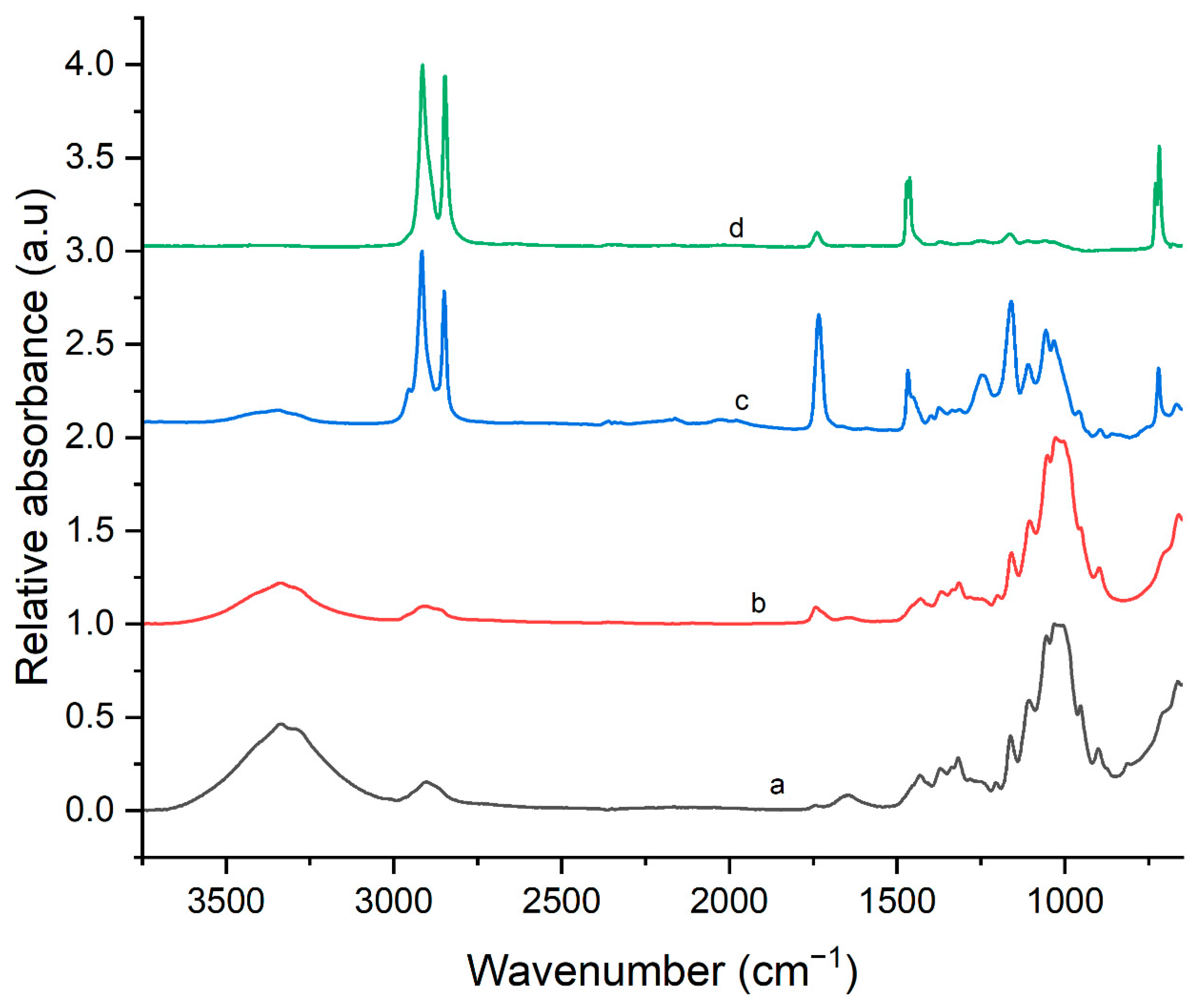
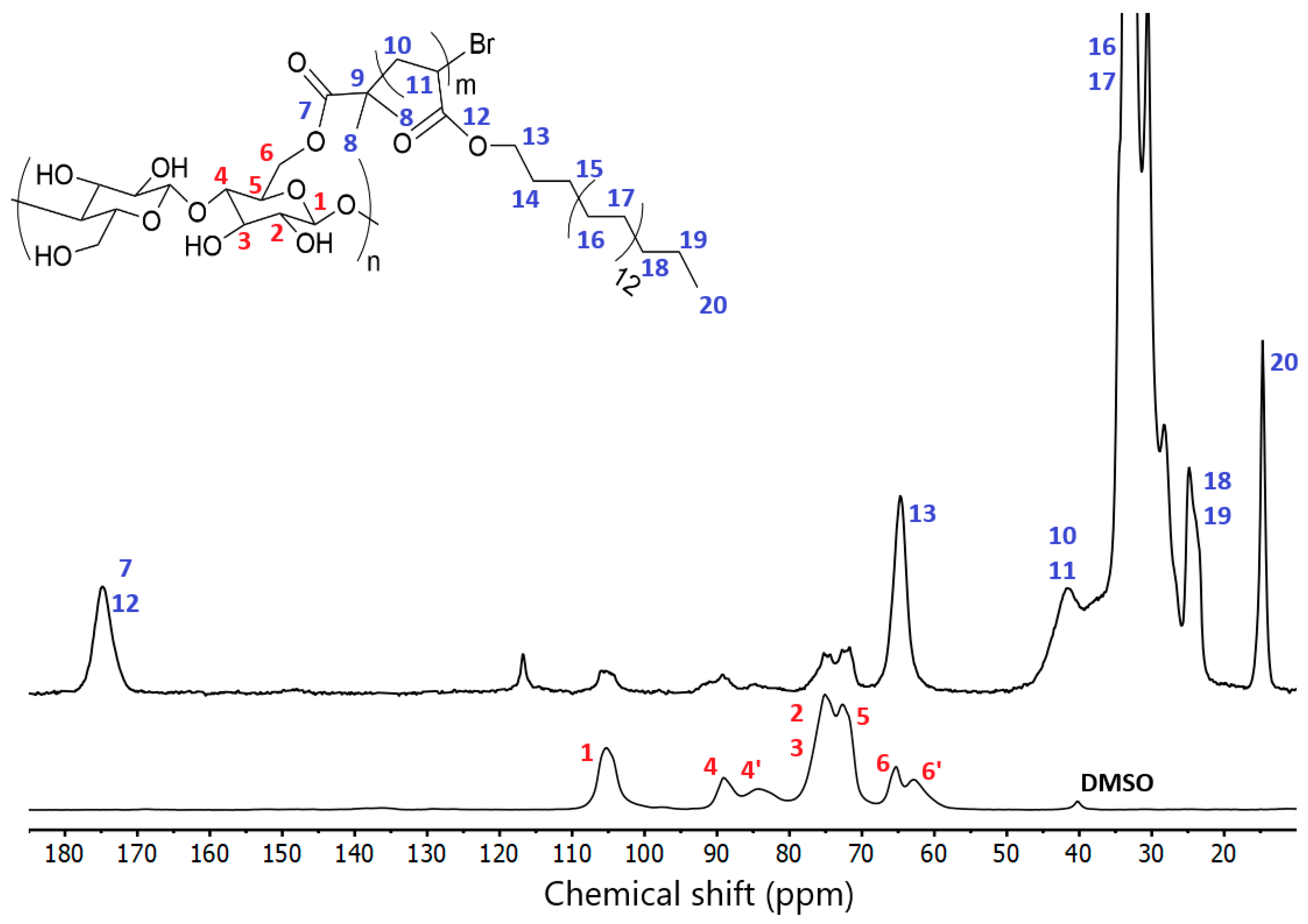
3.1. Chemical Surface Modification of Cellulose Nanofibrils

Several chemical surface modifications of the cellulose nanofibrils (CNFs) were required to ensure better compatibility between the nanocellulose filler and the high-density polyethylene matrix. This surface modification of the nanocellulose through surface-initiated single-electron transfer living radical polymerization (SI-SET-LRP) was previously used and detailed by Navarro et al. [37], and the strategy was applied here as outlined. By grafting stearyl acrylate chains in the fibrils, this process aimed to decrease their hydrophilic character, thus, limiting their aggregation due to fibril–fibril interactions [39,40]. Grafted cellulose could be completely suspended in toluene, which was not possible for pristine nanocellulose [41], providing evidence that chemical properties were effectively altered. Through using this strategy, a better compatibility between the CNF and the HDPE host matrix could be achieved, making CNF a potential candidate as a reinforcing agent for the HDPE composite, enhancing the 3D printability of the HDPE composite.
Following the nanocellulose production with the microfluidizer, it was necessary to perform a solvent exchange from water to DMSO. The surface chemical modification occurred on the hydroxyl groups contained within the cellulose structure through esterification with 2-bromoisobutyric acid (Scheme 2a). This reaction yielded a CNF-based macroinitiator (CNF-MI) suitable for the SET-LRP reaction.
Scheme 2. (a) Synthetic process of the CNF-based macroinitiator (CNF-MI) and (b) polymerization onto CNF-based macroinitiator with the SA monomer through SET-LRP, yielding CNF-PSA.
Fibers 10 00091 sch002
An easy and robust way of grafting polymer chains onto the surface of the CNF-based macroinitiator was the use of surface-initiated polymerization SI-SET-LRP [42,43,44,45]. The CNF-based macroinitiator could initiate the polymerization reaction of the monomer stearyl acrylate in the presence of copper and a tetradentate tertiary amine ligand (Me6TREN), as shown in Scheme 2b. This resulted in the incorporation of a saturated hydrocarbon chain, which dramatically increased the hydrophobicity of the CNF.
After polymerization, the PSA-grafted CNF was obtained as a translucid gel, and suspended in a nonpolar solvent such as toluene.
The chemical modifications of CNF were evaluated using ATR-FTIR (Figure 1). Pristine nanocellulose characteristic (Figure 1a) bands could be easily identified with bands located at 3320 cm−1 (O-H), 2950 and 2895 cm−1 (C-H), 1430 cm−1 (C-H) and 1161 cm−1 (C-O-C). The CNF-MI was successfully synthesized, and in comparison to the pristine CNF, its spectra (Figure 1b) revealed the presence of an additional absorption band localized at 1733 cm−1, attributed to the ester groups (C=O).
Following the SET-LRP reaction, the spectrum of CNF-PSA (Figure 1c) exhibited a significant increase in the number of bands. The key characteristic absorption bands were localized at 2916 and 2848 cm−1 (C-H), 1736 cm−1 (C=O), 1470 cm−1 (C-H), 1159 cm−1 (C-O-C) and 721 cm−1 (-CH2-).
Unmodified CNF and CNF-PSA were also studied using CP/MAS 13C-NMR, and their spectra are presented in Figure 2 with their respective peak assignments. Typical unmodified CNF peaks (shown in red) were found at 105 ppm for C1, with duplicated contributions for C4 and C6 signals, due to crystalline (89 ppm and 65 ppm) and amorphous (84 ppm and 62 ppm) regions, with the remaining carbon signal (C2, C3 and C5) clustered in the 72–75 ppm region [46]. After the addition of stearyl acrylate, an increase in peak density was observed. There was a peak at 175 ppm corresponding to the carbonyl bonds (C12), and intense peaks in the 40–20 ppm were observed for long alkyl chains grafted onto the CNF (C14 to C20). These results demonstrated the introduction of new esters and abundant methylene groups throughout the overall structure; therefore, successful chemical modification of the CNF could be deduced.

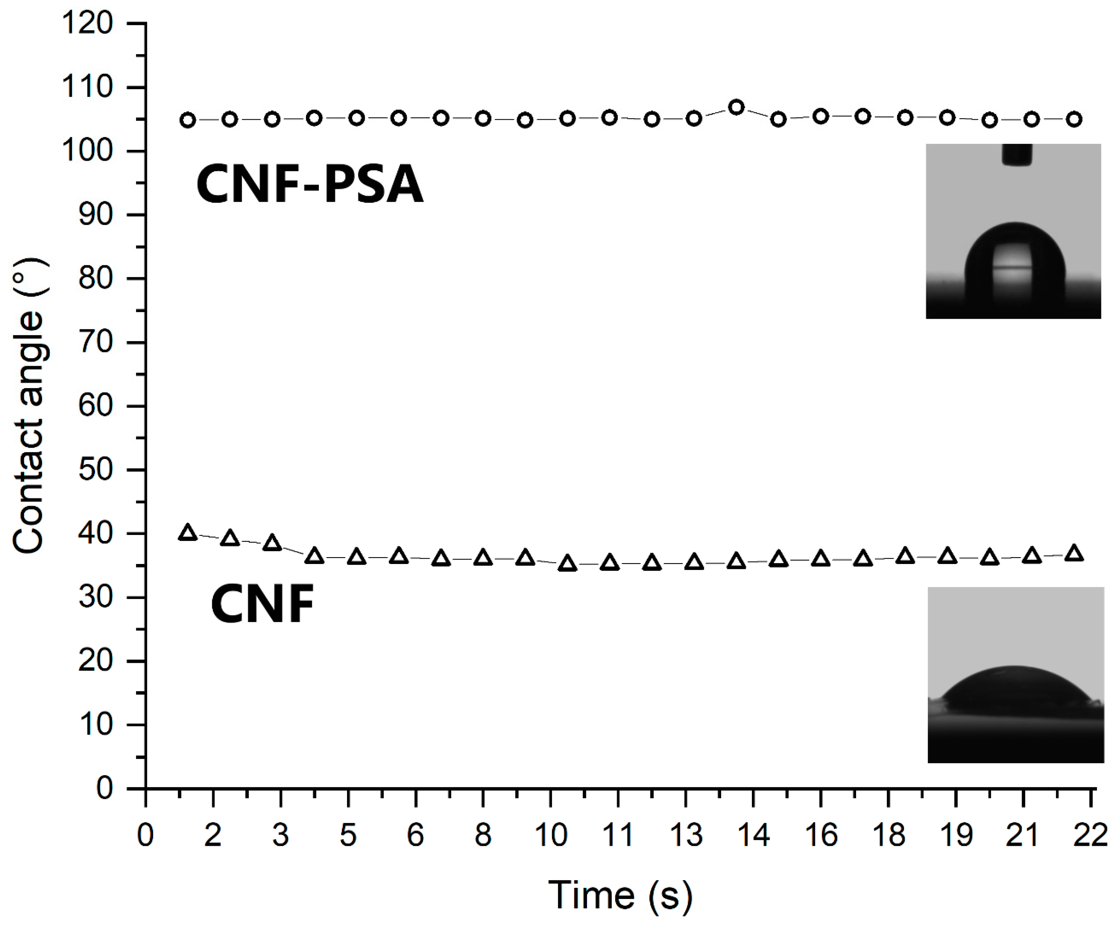
3.2. Surface Wetting Analysis

The modification of the cellulose nanofibrils led to the incorporation of multiple stearyl acrylate chains. The physical characteristics were expected to be altered, with a marked increase in hydrophobicity. To confirm this, the water contact angle of each specimen was measured. Therefore, CNF and CNF-PSA films were prepared for testing. A significant increase in the water contact angle on the films is shown in Figure 3 (from 36° to 105°). This phenomenon proved the high degree of hydrophobicity of CNF-PSA and, hence, the successful chemical modification.

3.3. Composite Production and Characterization

The nanocomposite formulation was composed of HDPE and the modified CNF-PSA, which were both completely dried before compounding. The compounding was carried out using a twin-screw extruder at 150 °C with a filler CNF-PSA content of 10 wt.%. ATR-FTIR was carried out on the extruded CNF-PSA/HDPE nanocomposite at 150 °C, and its spectrum is shown in Figure 1d. The distinctive high-density polyethylene bands [47,48] were easily recognizable, such as at 2912 and 2846 cm−1 (C-H) and the rocking peak near 719 cm−1 (-CH2). However, additional adsorption bands were located at 1741 cm−1 (C=O) and 1165 cm−1 (C-O-C), which proved that ester groups were contained in the extruded filament and, thus, ensured proper integration of the CNF-PSA into the HDPE.

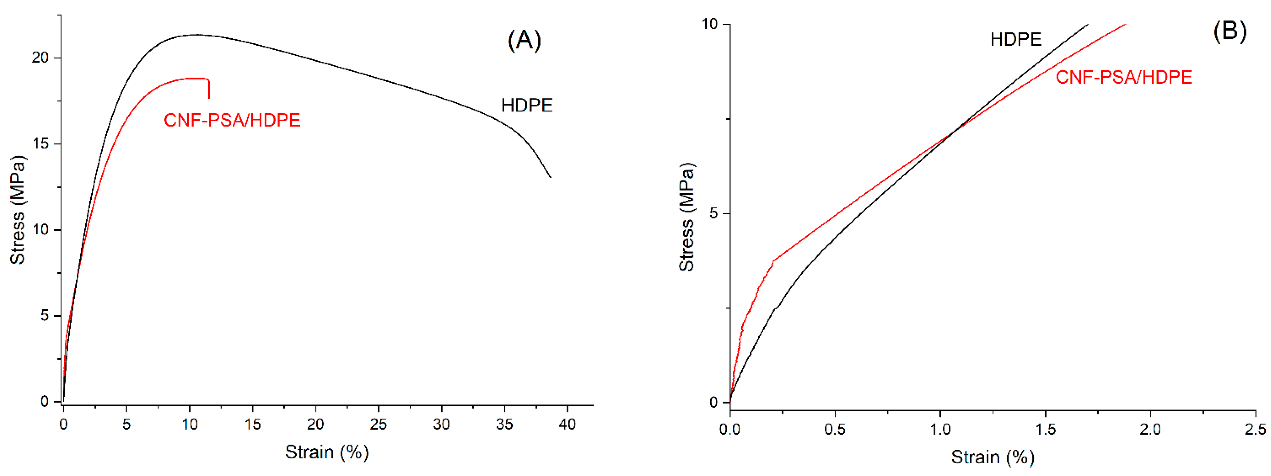
3.4. Mechanical Properties

Depending on the filler’s size, shape, dispersion and interaction/adhesion with the matrix and the inherent properties of the matrix, the composite could have distinct and different mechanical properties [49,50,51,52,53]. Figure 4 shows typical stress–strain curves of neat HDPE and HDPE/CNF-PSA composite. The recorded data after HDPE necking were removed for better observation. The table shows the mechanical properties of the composite and neat HDPE, i.e., the Young’s modulus, tensile strength and strain at the break of each material. A minimum of five samples were run for each case and the values shown, in Table 1, are the averages of these results.
A general improvement in the overall mechanical properties was observed upon the addition of CNF-PSA. The greatest Young’s modulus recorded was 1094 MPa with an improvement of approximately 23% for the composite. However, a slight decrease in tensile strength and a considerable drop in elongation at break were observed. This phenomenon was caused by the increasing stiffness due to the filler possessing this characteristic. This has been reported in other research papers as well [54,55,56]. The fracture of material was driven mainly through crack initiation and propagation, which in turn, with increasing filler content, led to an increase in graininess and agglomeration, resulting in areas requiring lower energy for fracture initiation or propagation [57]. This was supported by the lack of necking elongation of the composite samples under tensile stress as opposed to neat HDPE.

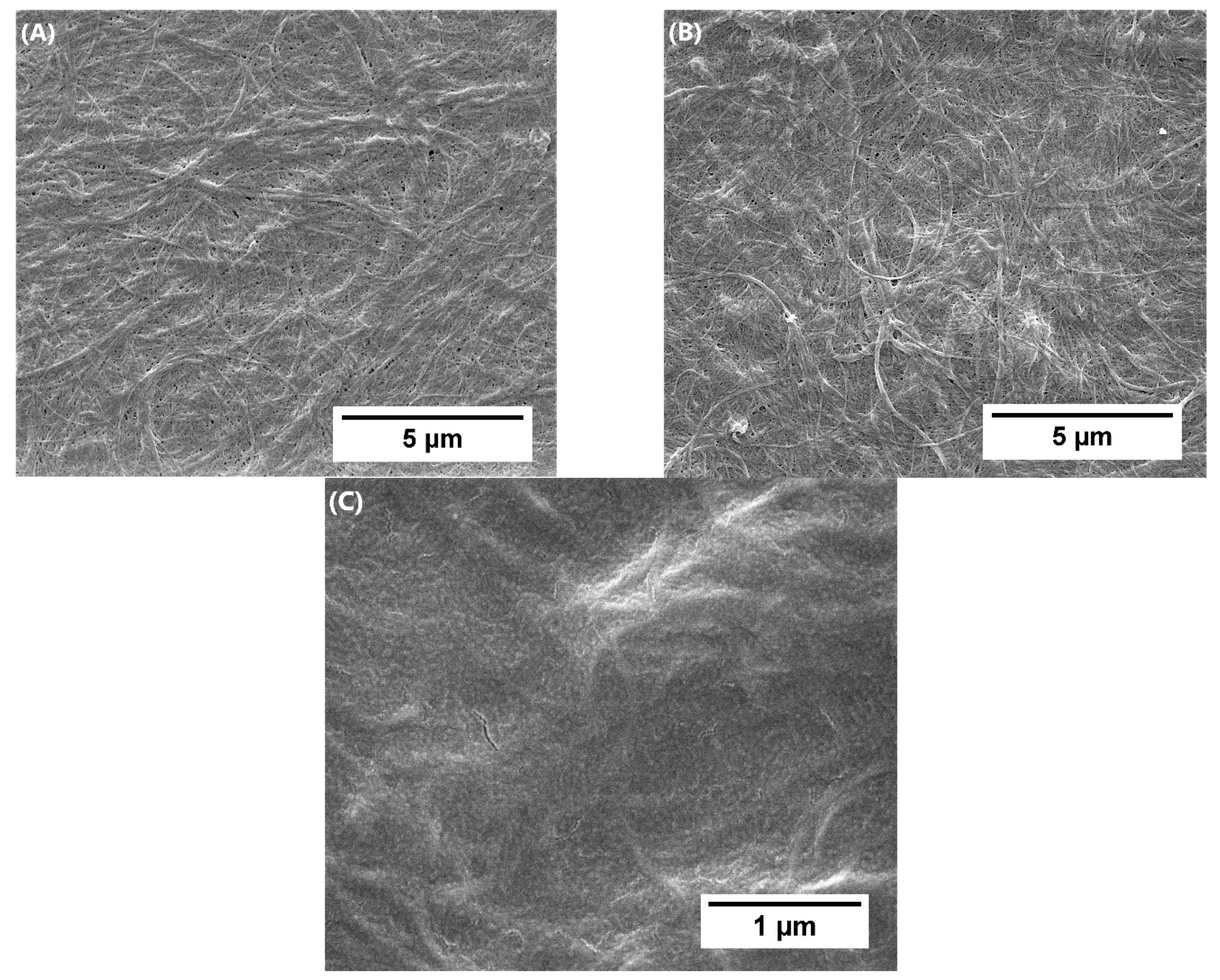
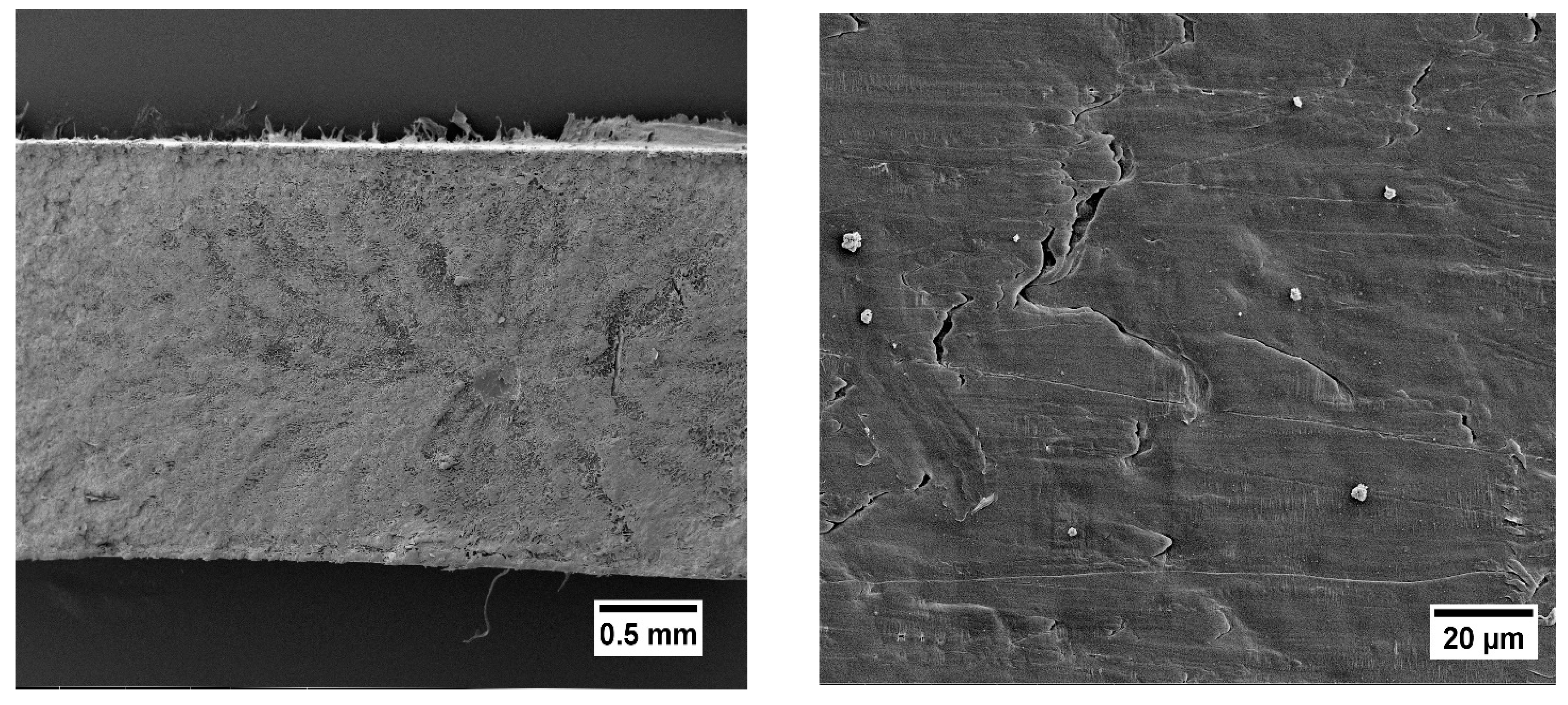
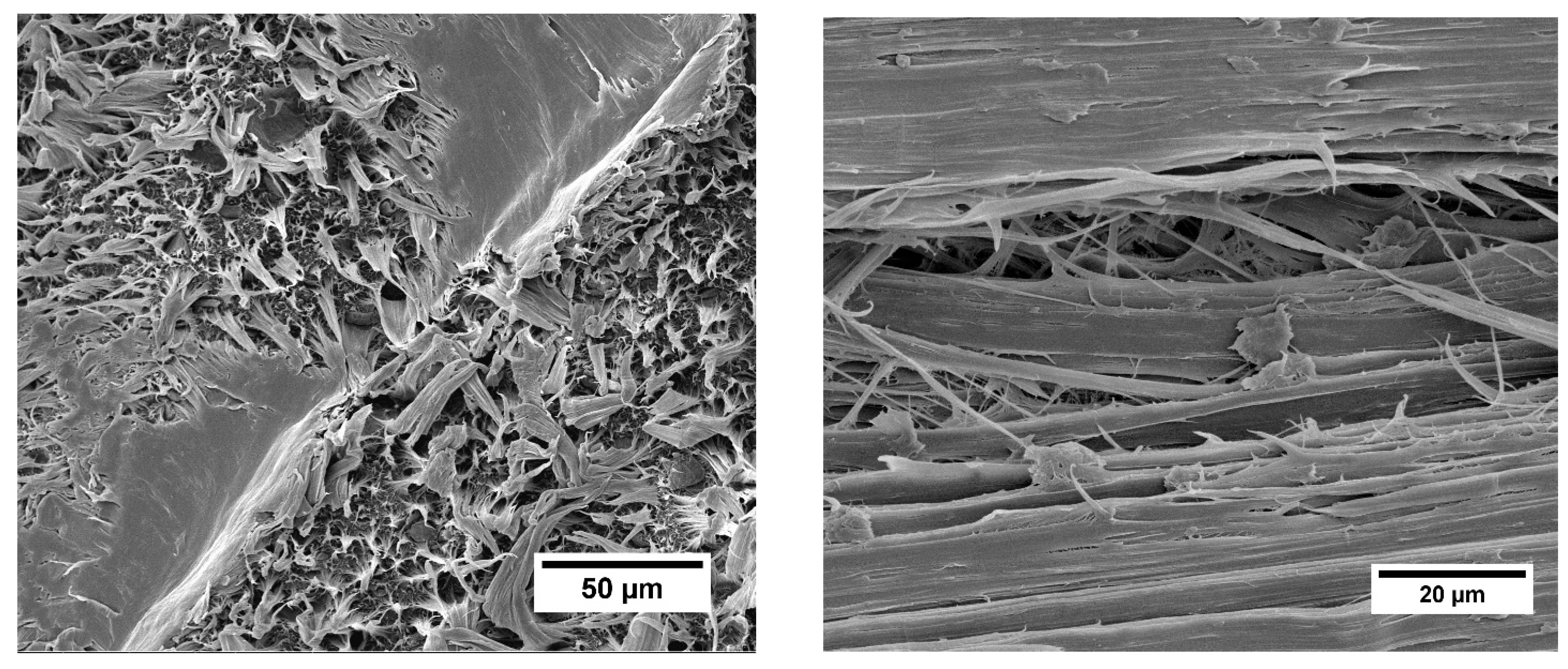
3.5. Morphological Analysis

In order to verify the nanofibrous morphology after the chemical modification, cellulose, CNF-based macroinitiator and CNF-PSA adducts were characterized by field emission scanning electron microscopy (FE-SEM). Images of the cellulose and CNF macroinitiator (Figure 5A,B) revealed a dense network of aggregated fibrils, with very few differences following the initial chemical modification. In contrast, the CNF-PSA images (Figure 5C) contained no discernable fibers, indicating that they were fully embedded in the grafted polymer matrix. This result confirmed that a modification of the properties of the cellulose nanofibrils took place. Successful grafting of poly stearyl acrylate, therefore, led to better compatibility with the hydrophobic polymer.
Figure 6 displays a cross-section of the composite mechanical testing specimen before fracture and extrusion at 150 °C. It could be seen that the surface smoothness was slightly reduced by the occurrence of a few tiny aggregates. Nevertheless, as a whole, we concluded that the surface was clear, without voids or large fiber aggregates. The broken surface was homogeneous, indicating the good adhesion between the CNF-PSA and the HDPE matrix. This demonstrated the CNF strengthening effect on the matrix polymer. Figure 7 shows the fractured cross-section surface of a tested specimen. The absence of cavities and irregularities confirmed that there was good interfacial bonding of the filler and matrix polymer. For comparison, attempts were made to produce composites of unmodified CNF with the HDPE matrix. Unfortunately, this was not possible, mainly due to the large macroscopic aggregation of CNF. The reason for poor dispensability was the hydrophilic properties that were not compatible with the hydrophobic polymer. These data indicated the necessity of having the chemical modification to render the initially hydrophilic CNF into the much more compatible CNF-PSA.

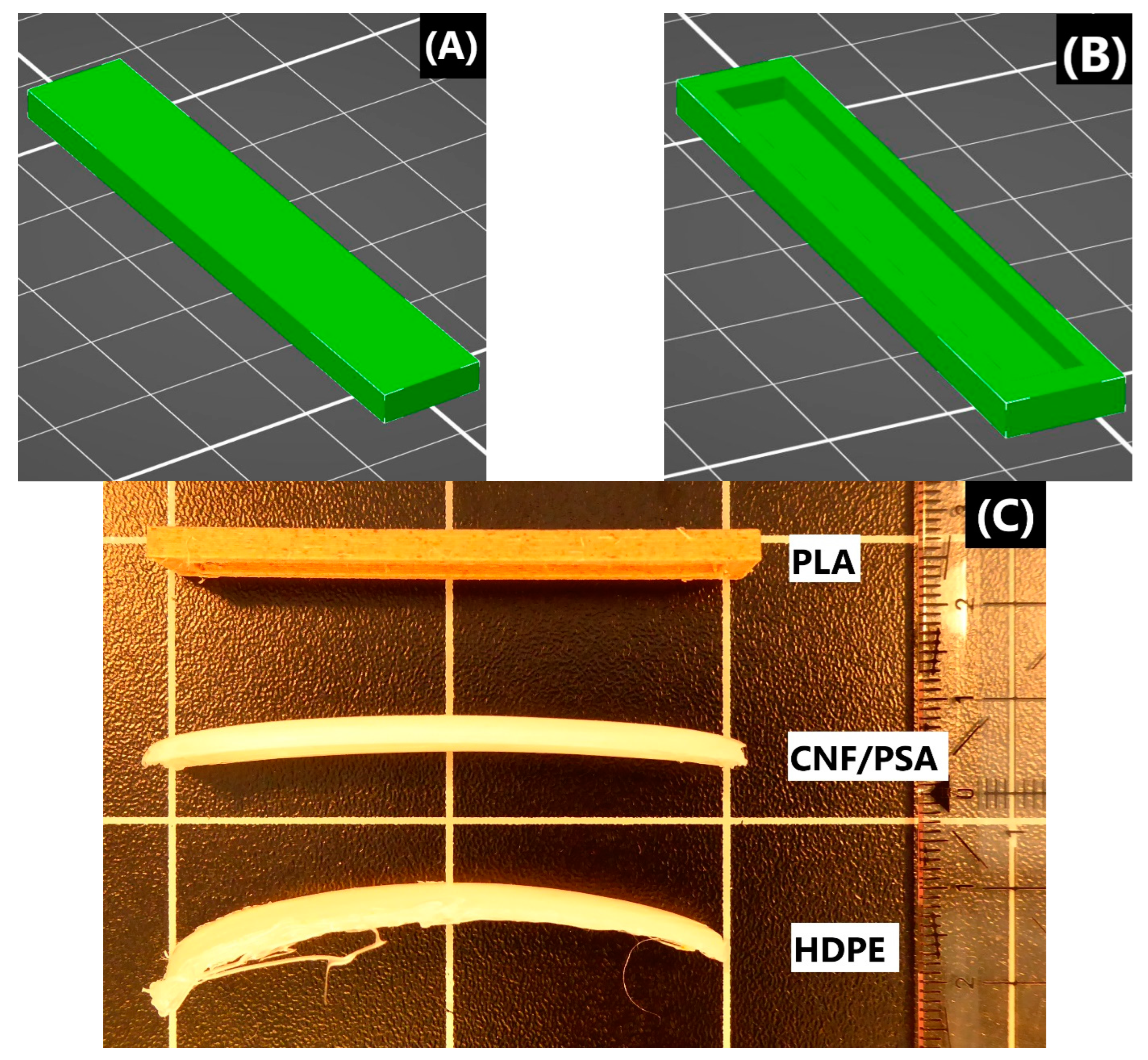
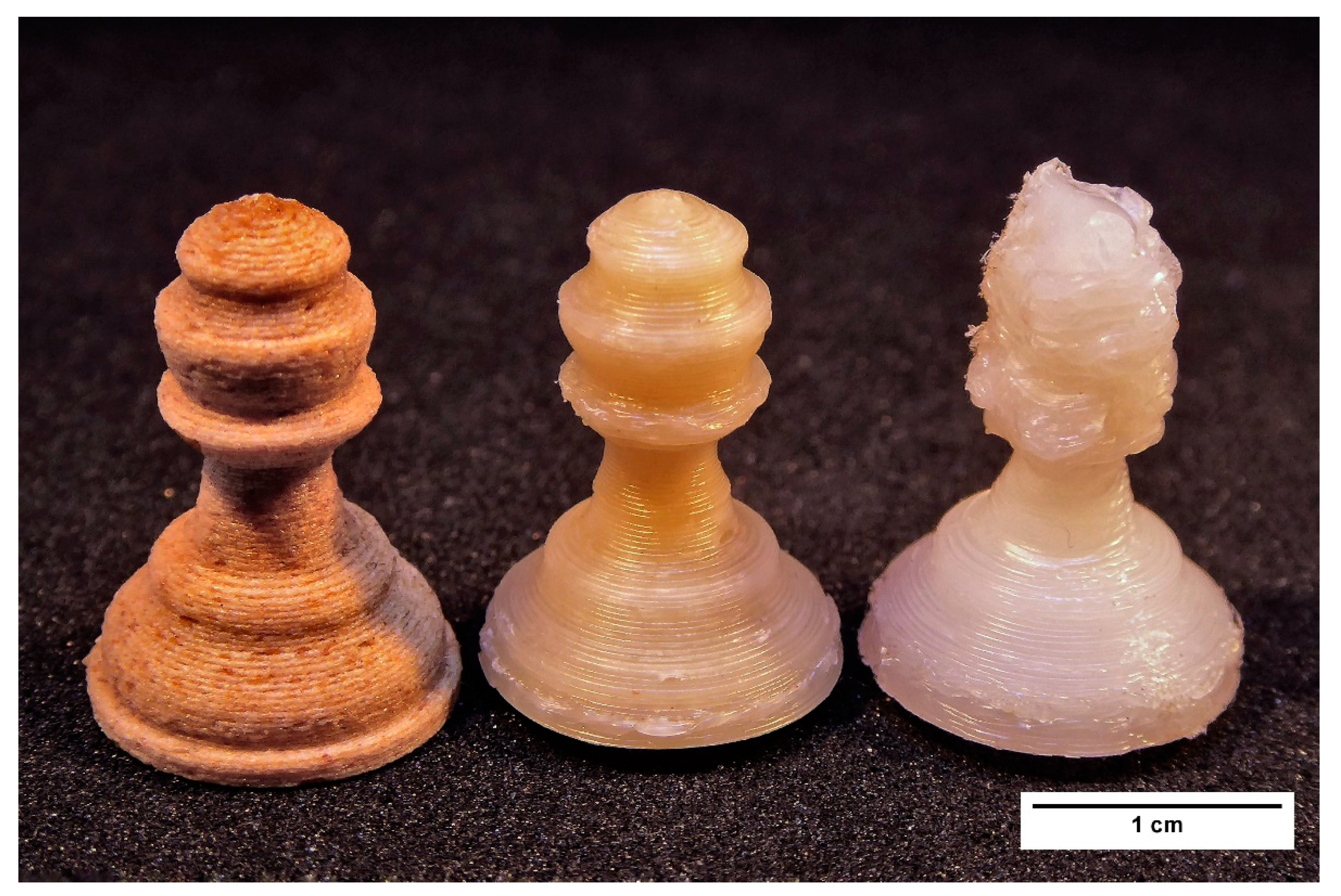
3.6. Printability of Neat HDPE and HDPE Composites

High-density polyethylene has hardly ever been suggested as a filament for fused deposition modeling. Where it is being sold as a 3D-printing filament, it is stated by the manufacturer that no reliable method of printing is available [58]. This is because HDPE is prone to shrinkage, bending and deformation as its temperature cools down [59], which significantly hinders its printing. However, it has been found that composites with improved mechanical properties show better printability [60,61,62]. It was then expected that the composite HDPE/CNF-PSA would have better printability compared to the neat HDPE. Schirmeister and his teammates [63] managed to 3D print complex designs with commercial HDPE while preventing shrinkage, warping and voiding. The surface quality of the printed HDPE was improved by adjusting the printing parameters. The printing parameters employed were: a nozzle temperature of 215 °C and bed temperature of 60 °C.
Designs which were difficult for a semicrystalline polymer to print were chosen to demonstrate the improvement in 3D-printing quality. Two cuboid designs were created, each 60 mm long, 10 mm wide and 3 mm high, one being solid and the second hollow, as shown in Figure 8. The hollow model was expected to undergo less deformation than the solid model. This was due to the fact that the full design contained a greater number of layers that could contribute to the overall deformation. Such models were subject to post-printing deformation problems, such as not adhering to the 3D printer’s surface and warping. These items tended not to remain flat but rather to bend. Thus, to quantify their deformation, the distorted specimens were assumed to belong to an arc of a circle, and the radius was calculated. With less deformation of the cuboid, the size of the circle was larger; hence, the radius was larger. Several parameters affecting print quality were investigated in this experiment, including printing on an LDPE-based tape, which is known to improve the adhesion of HDPE and closure for temperature stabilization [63]. Results are shown in Table 2 and Table 3.
In both models, the HDPE and composite failed to give satisfactory results without the addition of LDPE tape or closure (samples 1–2 and 7–8), reflecting the poor suitability of HDPE for printing. In contrast, improved performance was observed when the LDPE tape was applied to the printer bed. For samples 3 and 4, the composite was able to produce prints, whereas the HDPE was unable to do so. Lastly, for samples 5–6 and 9–12, an increase in radius ranging from 58% (samples 5–6) to 222% (samples 11–12) was observed for the designs produced using the composite filament versus the one produced using HDPE. The increase in radius indicated that there was less deformation. Cuboids printed with CNF-PSA-reinforced composite filament showed significantly less warpage than those printed with HDPE, proving the strengthening and enhancing effect of the filler and, thus, its relevance in allowing HDPE to be 3D printed with a higher definition.
Then, a chess pawn was printed using filaments composed from HDPE, CNF-PSA/HDPE and Woodfill for reference. The production of this pattern was challenging because of some difficulties, such as overhangs, that could hinder the printing process. Figure 9 is a representative picture of the pawns produced using the same printing parameters.
As expected, there were no issues with printing the pawn using Woodfill filament, which was used as a standard. However, the printing using HDPE filament proved to be less successful, because the upper part of the pawn failed to print the set structure and rather collapsed. The pawn produced using CNF-PSA/HDPE filament exhibited significant resolution and overall print quality improvements. Smoother lines, reduced warpage and better layer definition with good dimensional accuracy were achieved.

4. Conclusions

In summary, it can be stated that CNF grafted with poly stearyl acrylate proved to be an efficient filler for producing a new HDPE-based filament suitable for 3D printing. First of all, we converted CNF to a CNF-based macroinitiator through an esterification reaction. Then, the cellulosic fiber surface was hydrophobized through surface-induced radical graft polymerization, SET-LRP, and stearyl acrylate groups were incorporated. A nanocomposite of HDPE with 10% CNF-PSA filler was produced with twin-screw extrusion at 150 °C. Tensile testing of the HDPE and composite demonstrated an increase of 23% in the Young’s modulus (888 MPa to 1094 MPa). The compatibility was confirmed with a morphological analysis (SEM). An improvement in the printing quality was demonstrated with the printing of two models and measurements of their deformation. The warping was quantified with the measurement of the radius corresponding to each specimen, and an increase of 58 to 222% in the radius was noted. The composite was found to exhibit much less warpage compared to neat HDPE. Finally, pawns of chess using Woodfill, composite and pure HDPE filaments were printed. These prints demonstrated that HDPE/CNF-PSA filament had good printability and higher resolution than HDPE neat. The conclusion could be drawn that the CNF-PSA filler exhibited thermoplastic behavior and a high compatibility with HDPE.

Author Contributions

All authors: F.D., J.B.M. and J.R.G.N. contributed to the study, conception and design of the experiments. The synthesis and material preparations were performed by F.D. The data collection and analyses were performed by F.D., J.B.M. and J.R.G.N. All authors: F.D., J.B.M. and J.R.G.N. contributed to writing the submitted version of the manuscript. All authors have read and agreed to the published version of the manuscript.

Funding

J. Navarro and all authors would like to express our thanks to the Fachagentur Nachwachsende Rohstoffe e.V. (FNR/BMEL, HolzMat3D project, number 2220HV024X) for their financial support.

Institutional Review Board Statement

Not applicable.

Informed Consent Statement

Not applicable.

Data Availability Statement

Not applicable.

Acknowledgments

We would like to thank T. Potsch for the FE-SEM imaging. We are also grateful to J. Beruda for the tensile test measurements.

Conflicts of Interest

The authors declare no competing financial interests.

References

  1. Gao, W.; Zhang, Y.; Ramanujan, D.; Ramani, K.; Chen, Y.; Williams, C.B.; Wang, C.C.L.; Shin, Y.C.; Zhang, S.; Zavattieri, P.D. The Status, Challenges, and Future of Additive Manufacturing in Engineering. Comput. Des. 2015, 69, 65–89. [Google Scholar] [CrossRef]
  2. Motyl, B.; Filippi, S. Trends in Engineering Education for Additive Manufacturing in the Industry 4.0 Era: A Systematic Literature Review. Int. J. Interact. Des. Manuf. 2021, 15, 103–106. [Google Scholar] [CrossRef]
  3. Patel, D.K.; Dutta, S.D.; Shin, W.-C.; Ganguly, K.; Lim, K.-T. Fabrication and Characterization of 3D Printable Nanocellulose-Based Hydrogels for Tissue Engineering. RSC Adv. 2021, 11, 7466–7478. [Google Scholar] [CrossRef]
  4. Mohamed, O.A.; Masood, S.H.; Bhowmik, J.L. Optimization of Fused Deposition Modeling Process Parameters: A Review of Current Research and Future Prospects. Adv. Manuf. 2015, 3, 42–53. [Google Scholar] [CrossRef]
  5. Picard, M.; Mohanty, A.K.; Misra, M. Recent Advances in Additive Manufacturing of Engineering Thermoplastics: Challenges and Opportunities. RSC Adv. 2020, 10, 36058–36089. [Google Scholar] [CrossRef] [PubMed]
  6. Bandyopadhyay, A.; Bose, S.; Das, S. 3D Printing of Biomaterials. MRS Bull. 2015, 40, 108–115. [Google Scholar] [CrossRef] [Green Version]
  7. Wu, G.-H.; Hsu, S. Review: Polymeric-Based 3D Printing for Tissue Engineering. J. Med. Biol. Eng. 2015, 35, 285–292. [Google Scholar] [CrossRef] [Green Version]
  8. Chen, C.; Mehl, B.T.; Munshi, A.S.; Townsend, A.D.; Spence, D.M.; Martin, R.S. 3D-Printed Microfluidic Devices: Fabrication, Advantages and Limitations—A Mini Review. Anal. Methods 2016, 8, 6005–6012. [Google Scholar] [CrossRef] [Green Version]
  9. Attaran, M. The Rise of 3-D Printing: The Advantages of Additive Manufacturing over Traditional Manufacturing. Bus. Horiz. 2017, 60, 677–688. [Google Scholar] [CrossRef]
  10. Bartolomé, E.; Bozzo, B.; Sevilla, P.; Martínez-Pasarell, O.; Puig, T.; Granados, X. ABS 3D Printed Solutions for Cryogenic Applications. Cryogenics 2017, 82, 30–37. [Google Scholar] [CrossRef]
  11. Rojas-Martínez, L.E.; Flores-Hernandez, C.G.; López-Marín, L.M.; Martinez-Hernandez, A.L.; Thorat, S.B.; Reyes Vasquez, C.D.; Del Rio-Castillo, A.E.; Velasco-Santos, C. 3D Printing of PLA Composites Scaffolds Reinforced with Keratin and Chitosan: Effect of Geometry and Structure. Eur. Polym. J. 2020, 141, 110088. [Google Scholar] [CrossRef]
  12. Sieradzka, M.; Fabia, J.; Biniaś, D.; Graczyk, T.; Fryczkowski, R. High-Impact Polystyrene Reinforced with Reduced Graphene Oxide as a Filament for Fused Filament Fabrication 3D Printing. Materials 2021, 14, 7008. [Google Scholar] [CrossRef]
  13. Liu, F.; Vyas, C.; Poologasundarampillai, G.; Pape, I.; Hinduja, S.; Mirihanage, W.; Bartolo, P. Structural Evolution of PCL during Melt Extrusion 3D Printing. Macromol. Mater. Eng. 2018, 303, 1700494. [Google Scholar] [CrossRef] [Green Version]
  14. Li, J.; Yuan, S.; Zhu, J.; Li, S.; Zhang, W. Numerical Model and Experimental Validation for Laser Sinterable Semi-Crystalline Polymer: Shrinkage and Warping. Polymers 2020, 12, 1373. [Google Scholar] [CrossRef]
  15. Cruz Sanchez, F.A.; Boudaoud, H.; Camargo, M.; Pearce, J.M. Plastic Recycling in Additive Manufacturing: A Systematic Literature Review and Opportunities for the Circular Economy. J. Clean. Prod. 2020, 264, 121602. [Google Scholar] [CrossRef]
  16. Vidakis, N.; Petousis, M.; Maniadi, A. Sustainable Additive Manufacturing: Mechanical Response of High-Density Polyethylene over Multiple Recycling Processes. Recycling 2021, 6, 4. [Google Scholar] [CrossRef]
  17. Fu, J.; Ma, Y. Mold Modification Methods to Fix Warpage Problems for Plastic Molding Products. Comput. Aided. Des. Appl. 2016, 13, 138–151. [Google Scholar] [CrossRef] [Green Version]
  18. Fischer, J. Handbook of Molded Part Shrinkage and Warpage; William Andrew: Norwish, NY, USA, 2013. [Google Scholar]
  19. Gudadhe, A.; Bachhar, N.; Kumar, A.; Andrade, P.; Kumaraswamy, G. Three-Dimensional Printing with Waste High-Density Polyethylene. ACS Appl. Polym. Mater. 2019, 1, 3157–3164. [Google Scholar] [CrossRef]
  20. Mora, A.; Verma, P.; Kumar, S. Electrical Conductivity of CNT/Polymer Composites: 3D Printing, Measurements and Modeling. Compos. Part B Eng. 2020, 183, 107600. [Google Scholar] [CrossRef]
  21. Spoerk, M.; Sapkota, J.; Weingrill, G.; Fischinger, T.; Arbeiter, F.; Holzer, C. Shrinkage and Warpage Optimization of Expanded-Perlite-Filled Polypropylene Composites in Extrusion-Based Additive Manufacturing. Macromol. Mater. Eng. 2017, 302, 1700143. [Google Scholar] [CrossRef]
  22. Zander, N.E.; Park, J.H.; Boelter, Z.R.; Gillan, M.A. Recycled Cellulose Polypropylene Composite Feedstocks for Material Extrusion Additive Manufacturing. ACS Omega 2019, 4, 13879–13888. [Google Scholar] [CrossRef] [PubMed] [Green Version]
  23. Jonoobi, M.; Harun, J.; Mathew, A.P.; Oksman, K. Mechanical Properties of Cellulose Nanofiber (CNF) Reinforced Polylactic Acid (PLA) Prepared by Twin Screw Extrusion. Compos. Sci. Technol. 2010, 70, 1742–1747. [Google Scholar] [CrossRef]
  24. Babaee, M.; Jonoobi, M.; Hamzeh, Y.; Ashori, A. Biodegradability and Mechanical Properties of Reinforced Starch Nanocomposites Using Cellulose Nanofibers. Carbohydr. Polym. 2015, 132, 1–8. [Google Scholar] [CrossRef] [PubMed]
  25. Saba, N.; Safwan, A.; Sanyang, M.L.; Mohammad, F.; Pervaiz, M.; Jawaid, M.; Alothman, O.Y.; Sain, M. Thermal and Dynamic Mechanical Properties of Cellulose Nanofibers Reinforced Epoxy Composites. Int. J. Biol. Macromol. 2017, 102, 822–828. [Google Scholar] [CrossRef] [PubMed]
  26. Vidakis, N.; Petousis, M.; Velidakis, E.; Spiridaki, M.; Kechagias, J.D. Mechanical Performance of Fused Filament Fabricated and 3D-Printed Polycarbonate Polymer and Polycarbonate/Cellulose Nanofiber Nanocomposites. Fibers 2021, 9, 74. [Google Scholar] [CrossRef]
  27. Lesovik, V.; Fediuk, R.; Amran, M.; Alaskhanov, A.; Volodchenko, A.; Murali, G.; Uvarov, V.; Elistratkin, M. 3D-Printed Mortars with Combined Steel and Polypropylene Fibers. Fibers 2021, 9, 79. [Google Scholar] [CrossRef]
  28. Eichhorn, S.J.; Dufresne, A.; Aranguren, M.; Marcovich, N.E.; Capadona, J.R.; Rowan, S.J.; Weder, C.; Thielemans, W.; Roman, M.; Renneckar, S.; et al. Review: Current International Research into Cellulose Nanofibres and Nanocomposites. J. Mater. Sci. 2010, 45, 1–33. [Google Scholar] [CrossRef] [Green Version]
  29. Kafy, A.; Kim, H.C.; Zhai, L.; Kim, J.W.; Van Hai, L.; Kang, T.J.; Kim, J. Cellulose Long Fibers Fabricated from Cellulose Nanofibers and Its Strong and Tough Characteristics. Sci. Rep. 2017, 7, 17683. [Google Scholar] [CrossRef] [Green Version]
  30. Lewandowska, A.E.; Inai, N.H.; Ghita, O.R.; Eichhorn, S.J. Quantitative Analysis of the Distribution and Mixing of Cellulose Nanocrystals in Thermoplastic Composites Using Raman Chemical Imaging. RSC Adv. 2018, 8, 35831–35839. [Google Scholar] [CrossRef] [Green Version]
  31. Jonoobi, M.; Harun, J.; Mathew, A.P.; Hussein, M.Z.B.; Oksman, K. Preparation of Cellulose Nanofibers with Hydrophobic Surface Characteristics. Cellulose 2010, 17, 299–307. [Google Scholar] [CrossRef]
  32. Ashori, A.; Babaee, M.; Jonoobi, M.; Hamzeh, Y. Solvent-Free Acetylation of Cellulose Nanofibers for Improving Compatibility and Dispersion. Carbohydr. Polym. 2014, 102, 369–375. [Google Scholar] [CrossRef] [PubMed]
  33. Sato, A.; Kabusaki, D.; Okumura, H.; Nakatani, T.; Nakatsubo, F.; Yano, H. Surface Modification of Cellulose Nanofibers with Alkenyl Succinic Anhydride for High-Density Polyethylene Reinforcement. Compos. Part A Appl. Sci. Manuf. 2016, 83, 72–79. [Google Scholar] [CrossRef]
  34. Cichosz, S.; Masek, A.; Rylski, A. Cellulose Modification for Improved Compatibility with the Polymer Matrix: Mechanical Characterization of the Composite Material. Materials 2020, 13, 5519. [Google Scholar] [CrossRef]
  35. Li, J.; Zhai, S.; Wu, W.; Xu, Z. Hydrophobic Nanocellulose Aerogels with High Loading of Metal-Organic Framework Particles as Floating and Reusable Oil Absorbents. Front. Chem. Sci. Eng. 2021, 15, 1158–1168. [Google Scholar] [CrossRef]
  36. Zhai, S.; Chen, H.; Zhang, Y.; Li, P.; Wu, W. Nanocellulose: A Promising Nanomaterial for Fabricating Fluorescent Composites. Cellulose 2022, 29, 7011–7035. [Google Scholar] [CrossRef]
  37. Navarro, J.R.G.; Edlund, U. Surface-Initiated Controlled Radical Polymerization Approach To Enhance Nanocomposite Integration of Cellulose Nanofibrils. Biomacromolecules 2017, 18, 1947–1955. [Google Scholar] [CrossRef]
  38. Thingiverse. Available online: https://www.thingiverse.com/thing:34017/files (accessed on 4 April 2022).
  39. Wang, L.; Ando, M.; Kubota, M.; Ishihara, S.; Hikima, Y.; Ohshima, M.; Sekiguchi, T.; Sato, A.; Yano, H. Effects of Hydrophobic-Modified Cellulose Nanofibers (CNFs) on Cell Morphology and Mechanical Properties of High Void Fraction Polypropylene Nanocomposite Foams. Compos. Part A Appl. Sci. Manuf. 2017, 98, 166–173. [Google Scholar] [CrossRef]
  40. Sharma, A.; Mandal, T.; Goswami, S. Dispersibility and Stability Studies of Cellulose Nanofibers: Implications for Nanocomposite Preparation. J. Polym. Environ. 2021, 29, 1516–1525. [Google Scholar] [CrossRef]
  41. Chu, Y.; Sun, Y.; Wu, W.; Xiao, H. Dispersion Properties of Nanocellulose: A Review. Carbohydr. Polym. 2020, 250, 116892. [Google Scholar] [CrossRef]
  42. Worthley, C.H.; Constantopoulos, K.T.; Ginic-Markovic, M.; Pillar, R.J.; Matisons, J.G.; Clarke, S. Surface Modification of Commercial Cellulose Acetate Membranes Using Surface-Initiated Polymerization of 2-Hydroxyethyl Methacrylate to Improve Membrane Surface Biofouling Resistance. J. Memb. Sci. 2011, 385–386, 30–39. [Google Scholar] [CrossRef]
  43. Morandi, G.; Heath, L.; Thielemans, W. Cellulose Nanocrystals Grafted with Polystyrene Chains through Surface-Initiated Atom Transfer Radical Polymerization (SI-ATRP). Langmuir 2009, 25, 8280–8286. [Google Scholar] [CrossRef] [PubMed]
  44. Zhang, Z.; Sèbe, G.; Hou, Y.; Wang, J.; Huang, J.; Zhou, G. Grafting Polymers from Cellulose Nanocrystals via Surface-initiated Atom Transfer Radical Polymerization. J. Appl. Polym. Sci. 2021, 138, 51458. [Google Scholar] [CrossRef]
  45. Bansal, A.; Singhal, N.; Panwar, V.; Kumar, A.; Kumar, U.; Ray, S.S. Ex Situ Cu(0) Nanoparticle Mediated SET-LRP of Methyl Methacrylate/Styrene-Methyl Methacrylate in a Biphasic Toluene–Water System. RSC Adv. 2017, 7, 11191–11197. [Google Scholar] [CrossRef] [Green Version]
  46. Mariño, M.A.; Rezende, C.A.; Tasic, L. A Multistep Mild Process for Preparation of Nanocellulose from Orange Bagasse. Cellulose 2018, 25, 5739–5750. [Google Scholar] [CrossRef]
  47. Gulmine, J.; Janissek, P.; Heise, H.; Akcelrud, L. Polyethylene Characterization by FTIR. Polym. Test. 2002, 21, 557–563. [Google Scholar] [CrossRef]
  48. Erbetta, C.D.C.; Manoel, G.F.; Oliveira, A.P.L.R.; Silva, M.E.S.R.E.; Freitas, R.F.S.; Sousa, R.G. Rheological and Thermal Behavior of High-Density Polyethylene (HDPE) at Different Temperatures. Mater. Sci. Appl. 2014, 5, 923–931. [Google Scholar] [CrossRef] [Green Version]
  49. Ponnamma, D.; Cabibihan, J.-J.; Rajan, M.; Pethaiah, S.S.; Deshmukh, K.; Gogoi, J.P.; Pasha, S.K.K.; Ahamed, M.B.; Krishnegowda, J.; Chandrashekar, B.N.; et al. Synthesis, Optimization and Applications of ZnO/Polymer Nanocomposites. Mater. Sci. Eng. C 2019, 98, 1210–1240. [Google Scholar] [CrossRef] [PubMed]
  50. Kerni, L.; Singh, S.; Patnaik, A.; Kumar, N. A Review on Natural Fiber Reinforced Composites. Mater. Today Proc. 2020, 28, 1616–1621. [Google Scholar] [CrossRef]
  51. Móczó, J.; Pukánszky, B. Polymer Micro and Nanocomposites: Structure, Interactions, Properties. J. Ind. Eng. Chem. 2008, 14, 535–563. [Google Scholar] [CrossRef]
  52. Gallos, A.; Paës, G.; Allais, F.; Beaugrand, J. Lignocellulosic Fibers: A Critical Review of the Extrusion Process for Enhancement of the Properties of Natural Fiber Composites. RSC Adv. 2017, 7, 34638–34654. [Google Scholar] [CrossRef]
  53. Qiu, K.; Netravali, A. In Situ Produced Bacterial Cellulose Nanofiber-Based Hybrids for Nanocomposites. Fibers 2017, 5, 31. [Google Scholar] [CrossRef] [Green Version]
  54. Houshyar, S.; Shanks, R.A.; Hodzic, A. The Effect of Fiber Concentration on Mechanical and Thermal Properties of Fiber-Reinforced Polypropylene Composites. J. Appl. Polym. Sci. 2005, 96, 2260–2272. [Google Scholar] [CrossRef]
  55. Liang, J.-Z. Effects of Tension Rates and Filler Size on Tensile Properties of Polypropylene/Graphene Nano-Platelets Composites. Compos. Part B Eng. 2019, 167, 241–249. [Google Scholar] [CrossRef]
  56. Ding, W.; Kuboki, T.; Wong, A.; Park, C.B.; Sain, M. Rheology, Thermal Properties, and Foaming Behavior of High d-Content Polylactic Acid/Cellulose Nanofiber Composites. RSC Adv. 2015, 5, 91544–91557. [Google Scholar] [CrossRef]
  57. Stinchcomb, W.; Reifsnider, K. Fatigue Damage Mechanisms in Composite Materials: A Review. In Fatigue Mechanisms; ASTM International: West Conshohocken, PA, USA; pp. 762–787.
  58. HDPE Filament—Natural—1.75 mm. Available online: https://filaments.ca/products/hdpe-filament-natural-1-75mm?variant=42590589320 (accessed on 30 April 2022).
  59. Pešić, N.; Živanović, S.; Garcia, R.; Papastergiou, P. Mechanical Properties of Concrete Reinforced with Recycled HDPE Plastic Fibres. Constr. Build. Mater. 2016, 115, 362–370. [Google Scholar] [CrossRef] [Green Version]
  60. Peng, F.; Jiang, H.; Woods, A.; Joo, P.; Amis, E.J.; Zacharia, N.S.; Vogt, B.D. 3D Printing with Core–Shell Filaments Containing High or Low Density Polyethylene Shells. ACS Appl. Polym. Mater. 2019, 1, 275–285. [Google Scholar] [CrossRef]
  61. Koffi, A.; Toubal, L.; Jin, M.; Koffi, D.; Döpper, F.; Schmidt, H.; Neuber, C. Extrusion-based 3D Printing with High-density Polyethylene Birch-fiber Composites. J. Appl. Polym. Sci. 2022, 139, 51937. [Google Scholar] [CrossRef]
  62. Ji, A.; Zhang, S.; Bhagia, S.; Yoo, C.G.; Ragauskas, A.J. 3D Printing of Biomass-Derived Composites: Application and Characterization Approaches. RSC Adv. 2020, 10, 21698–21723. [Google Scholar] [CrossRef]
  63. Schirmeister, C.G.; Hees, T.; Licht, E.H.; Mülhaupt, R. 3D Printing of High Density Polyethylene by Fused Filament Fabrication. Addit. Manuf. 2019, 28, 152–159. [Google Scholar] [CrossRef]
Scheme 1. Circular method: printed 3D models are represented as an arc.
Fibers 10 00091 sch001
Figure 1. ATR-FTIR spectra of pristine CNF (a), CNF-MI (b), CNF-PSA (c) and CNF-PSA/HDPE composite (d).
Fibers 10 00091 g001
Figure 2. CP/MAS 13C-NMR spectra of unmodified CNF on the lower part and CNF-PSA on the upper part.
Fibers 10 00091 g002
Figure 3. Photographs of the static contact angle measurements of water on unmodified CNF and CNF-PSA films, and the evolution of the contact angle against time. The CNF-PSA film has a contact angle of 105°, while unmodified film has a 36° contact angle.
Fibers 10 00091 g003
Figure 4. Experimental stress–strain curves of CNF-PSA/HDPE with neat HDPE; HDPE is represented by the black curve and red for the composite. Stress–strain curves (B) are zoomed versions of (A).
Fibers 10 00091 g004
Figure 5. FE-SEM images of (A) CNF, (B) CNF-based macroinitiator and (C) CNF-PSA.
Fibers 10 00091 g005
Figure 6. SEM images showing the cross-section of a broken mechanical test specimen composed with CNF-PSA/HDPE.
Fibers 10 00091 g006
Figure 7. SEM images of a broken mechanical test specimen composed with CNF-PSA/HDPE at fracture point.
Fibers 10 00091 g007
Figure 8. Three-dimensional models of full (A) and notched (B) designs; (C) is a representative photo of printed notched models.
Fibers 10 00091 g008
Figure 9. Three-dimensional printed models: filament used on the left pawn is Woodfill, HDPE for the middle and CNF-PSA/HDPE composite for the right one.
Fibers 10 00091 g009
Table 1. Summary of the tensile properties of the HDPE and composite of 10 wt.% of CNF-PSA/HDPE.
CNF Content in HDPE (%)Extrusion Temperature (°C)Young’s Modulus (MPa)Yield Strength (MPa)Strain at Break (%)
0150888 ± 13521.4 ± 0.338.6 ± 1.4
101501094 ± 7718.8 ± 0.111.6 ± 1.3
Table 2. Summary of warping measurements of HDPE and composite of 10 wt.% of CNF PSA/HDPE in the full model.
SampleMaterial UsedLDPE TapeClosureRadius (cm)
1HDPENoNo-
2CNF-PSA/HDPENoNo-
3HDPEYesNo-
4CNF-PSA/HDPEYesNo11.62
5HDPEYesYes7.80
6CNF-PSA/HDPEYesYes12.30
Table 3. Summary of warping measurements of HDPE and composite of 10 wt.% of CNF PSA/HDPE in the notched model.
SampleMaterial UsedLDPE TapeClosureRadius (cm)
7HDPENoNo-
8CNF-PSA/HDPENoNo-
9HDPEYesNo9.67
10CNF-PSA/HDPEYesNo23.57
11HDPEYesYes7.15
12CNF-PSA/HDPEYesYes23.05
Publisher’s Note: MDPI stays neutral with regard to jurisdictional claims in published maps and institutional affiliations.

