Effects of BIM-Based Construction of Prefabricated Steel Framework from the Perspective of SMEs


Department of Architectural Engineering, Hanyang University, 220 Wangsimni-ro, Seongdong-gu, Seoul 04763, Korea
*
Author to whom correspondence should be addressed.
Appl. Sci. 2019, 9(9), 1732; https://doi.org/10.3390/app9091732
Submission received: 11 February 2019
/
Revised: 22 April 2019
/
Accepted: 24 April 2019
/
Published: 26 April 2019
(This article belongs to the Special Issue BIM in the Construction Industry)
Abstract
:Small- and medium-sized enterprises (SMEs) are part of the building construction industry. Although many effect analyses of applying building information modeling (BIM) to projects have been conducted, analyses from the perspective of SMEs are lacking. We propose a BIM-based construction of prefabricated steel framework from the perspective of SMEs. We derive the essential functions of the system from the viewpoint of SMEs and verify the qualitative effect through a case analysis of prefabricated steel frame construction that is based on BIM. The following system functions and qualitative effects are analyzed according to project stages that are based on interviews of working groups participating in system development and case projects. (1) Preconstruction stage: extraction of fabrication drawing and review of shop drawing, (2) fabrication stage: prefabrication review, steel member removal, and field loading review, and (3) construction phase: integrated management of cost and schedule and quality management. The expected effects of applying the system are qualitatively and quantitatively analyzed through expert group interviews and surveys. For the quantitative analysis, an evaluation index is used for the end-user computing satisfaction survey. Further analysis of the finishing and installation work is required. Future research should also analyze the effect of system application on human resource management.
1. Introduction
Building information modeling (BIM) enables integrated design [1], and it can be applied to various fields (e.g., design verification, quantity calculation, and prefabrication) throughout the construction life cycle by utilizing the three-dimensional BIM model that is built for each construction type [2]. In the preconstruction phase, performing collision detection and design review using BIM can help to reduce the losses that occur in the construction phase by identifying the problems that can be solved beforehand at the design phase (e.g., design errors) [3,4]. Doing so improves the design quality by reducing design errors, design changes, and rework [5,6]. In the fabrication phase, the procurement process of construction frame members through BIM-based prefabrication can be simplified, and the productivity of workflow between the designers and constructors can be improved [7]. In addition, in terms of production productivity, the workers that are involved in the production of frame members can utilize the information inputted to BIM objects to support the manufacturing process; such information is parametric and it is not provided in the existing two-dimensional (2D)-based production work [8]. In the construction phase, a four-dimensional (4D) simulation can be implemented by linking the BIM model with the schedule [9]. A BIM-based 4D simulation combines information that is related to the process, equipment, and space to identify various uncertainties that arise during the process, and provides information that can be reviewed in advance (Moon et al., 2014). Thus, the effect of BIM on each phase of a construction project becomes clear.
However, previous studies on the effects of BIM on construction projects were conducted for large-scale projects [10]. Previous studies analyzed the return on investment (ROI) that was attained by general contractors for BIM-based construction projects [11,12,13]. Of course, many studies have analyzed the effects of BIM application from the viewpoint of small- and medium-sized enterprises (SMEs) [14,15,16,17]. However, studies on developing a BIM-based construction management system from the viewpoint of SMEs are lacking [18]. Due to the nature of SMEs, the sales and profits are not as large as those of large-scale enterprises, and many of them abandon the application of BIM, which involves high initial costs [19,20]. Therefore, we begin this study by analyzing the difficulties of managing a construction project from the viewpoint of SMEs. We propose a BIM-based construction management system framework to support SMEs. We also conduct a case study to verify the major functions that will be installed in the system for the potential SME users and their perceived performance.
2. Literature Review
2.1. Characteristics of SMEs in Construction Management
In 2016, 99.5% of the 5.5 million businesses in the United Kingdom (UK) were classified as SMEs, accounting for 60% of all private sector employment in the UK and a huge proportion of the 240,000 construction service providers that are operating within the UK [21]. The latest set of government business population estimates shows that the number of construction companies with less than 50 employees has increased to over 1,005,290, up from 972,475 in 2016. The data also indicate that these small businesses are responsible for an approximate total turnover of over £185 Bn a year, up from £172 Bn in 2016. The total turnover of all the businesses operating in the construction sector reached £296.8 Bn in 2017, up from £271.9 Bn in 2016 [22]. The Department for Business, Enterprise, and Regulatory Reform (BERR) [23] defines the size of a firm in terms of the number of employees (see Table 1). The BERR defines
- micro-sized companies as those having fewer than 10 employees,
- small-sized companies as those having fewer than 50 employees,
- medium-sized companies as those having between 50 and 249 employees, and
- large-sized companies as those having 250 employees or above.
A previous study outlined the characteristics of SMEs, as follows [24]. Many SMEs do not record procedures in a clear format, unlike large-scale companies [25]. Thus, SMEs’ management style is flexible and informal. For example, one of the main methods for communicating information is through informal interviews between individuals. Therefore, a fundamental limitation in identifying human resources to be used in construction projects and undertaking construction management based on quantitative information exists. Moreover, SMEs may face difficulties in raising funds and maintaining adequate cash flow, which thus limits continued capital investment in employee education and technology development [26]. As such, SMEs that participate in construction projects have common limitations with regard to improving their business systems. However, owners/managers of SMEs play a key role in the decision-making process [27,28]. Thus, if the outcomes of business process reengineering (BPR) are clear, the SME may be more likely to change and in a more flexible manner, when compared to their large-scale counterparts. Therefore, this study proposes a BIM-based construction management system framework from the perspective of SMEs.
2.2. Limitations of BIM Adoption
Many previous studies have analyzed BIM application and its effects [1,2,3,4,5,6,7,8,9]. However, most of this research is limited to case studies, such as loss prevention due to design errors for a single project [3,4]. Moreover, the studies focused on improving design quality, which is difficult to quantify [5,6]. Some works analyzed the effect of BIM application on interference checking and conducted a 4D simulation for a specific task [9]. Ideally, BIM supports all of the project participants using data on the construction life cycle. However, it is difficult to improve the process and achieve the business integration effect using BIM in large organizations [7].
Moreover, it is difficult to manage the inputted manpower by only using BIM data for the building. As a result, research on the application of the internet of things to manage workers by attaching wireless sensors to helmets is also being conducted [29]. In addition, BIM does not immediately reflect implementation via a virtual model. As a result, laser scan and image scan technologies have been introduced as tools for creating and integrating real models. Additionally, the concept of digital twin, which combines virtual models and real models to pre-simulate specific issues, may be used. Indeed, recent studies have tended to integrate not only BIM, but also various other technologies (e.g., three-dimensional (3D) laser scanning, augmented reality, mobile computing, wireless connection, quick response codes) with building construction management [30].
Existing BIM-based construction management systems (e.g., a project management information system; PMIS) should be accompanied by BPR, because the system is often constructed at the enterprise level [31]. In addition, the scope of the system construction is very wide, because the project characteristics of various business areas, rather than a single project, should be considered. Each division of the company should devise the system to address all of the diverse functions that are required. Some companies report issues that are caused by the presence of several project-related databases and the fact that security concerns limit system accessibility for the users. In this paper, we propose a BIM-based construction management system from the viewpoint of SMEs. In addition, we qualitatively verify the functioning of the system through a case analysis.
2.3. BIM for Prefabricated Steel Frame Construction
A general contractor manages the various specialty contractors that are involved in a construction project. A steel frame construction is implemented through a specialty contractor. Steel frame construction involves prefabricating materials at a factory that are based on a preconstruction blueprint [32]. Generally, in the preconstruction phase, the design drawings and specifications are reviewed, the construction companies are selected, and the construction plans and details are prepared [33]. The factory processing of the steel frame members is conducted in the order of full-size drawing, prototyping, deformation inspection, marking gauge, cutting and machining, drilling, joining, riveting and welding, metal cutting, rustproofing, and loading at the site. When the steel frame members are brought to the laydown area, they are then assembled by bolting or welding, depending on the installation drawing. Lastly, a crane is used to lift the steel frame members, and the workers complete the installation process [34,35].
However, if any design changes are made to the steel frame, the following problems may arise [33]: (1) Increase in construction costs and a delay in construction period due to the need to place new orders for materials and/or additional production, (2) surplus of preordered materials, and (3) duplicate production of steel frame members. These costs and risks due to the delay can impact the profits of the specialty contractors. It is necessary to introduce BIM and other recent technologies (e.g., laser scanning) to solve these problems.
Table 1 lists the main functions and effects of BIM. A 3D BIM model with object information is created from a 3D BIM conversion design based on the drawings that were generated at the design stage, and the 3D BIM model is visualized for collaboration among experts in different fields [36]. In addition, the clash check function helps to improve the quality of the 2D design drawings by examining the inter-member clash and reducing errors therein in terms of potential errors that may occur at the preconstruction site [13]. Parametric modeling—a popular BIM technique—is used to project and automatically change the information that is associated with each member when the design is changed. Thus, the design process is more quickly and accurately completed. Table 1 lists the effects of information utilization using BIM in the design and construction phases.
Table 2 lists the research highlights of previous studies that used BIM for modeling productivity, shop drawing calculation, and process management in steel frame construction.
Previous studies focused on improving the productivity of the unit tasks of steel frame construction (e.g., automatic modeling of joints and drawings) and managing the process. However, the SMEs need to derive the effects of BIM for tasks that are related to the design, fabrication, and construction, rather than applying the technology to the unit tasks. This study presents a case study on steel frame construction to verify the main BIM-based construction management function to be installed in the system for an SME.
2.4. Evaluation of Information System
Information systems (e.g., PMIS) that were used in existing enterprises possess different characteristics depending on their purpose and support tasks. Information systems are classified according to their purpose and functionalities that are based on the requirements of the company [48,49]. Other works have analyzed the characteristics of information systems according to their contribution to efficiency improvement and relationship improvement in the internal and external aspects of the company [50,51]. Research regarding the success of information systems is based on the work of Shannon and Weaver and Mason [52,53], and the results suggest that the level of information can be measured in terms of the technical, semantic, and effectiveness levels [54]. However, the usefulness of such evaluations is limited for the following reasons. First, it is difficult to quantify the measurement factors and objectively separate the effects of the information system from other aspects [55,56,57]. As a result, attempts have been made to evaluate the information systems in terms of their use as well as the end user’s satisfaction (i.e., considering the user’s cognitive aspect). However, Lucas [55] argued that, while indicators pertaining to an actual information system (such as measured time) are somewhat objective and easy to quantify, they are not a useful measure, because the use of the information system may be compulsory. Thus, in many studies, end-user satisfaction, rather than evaluation of use, is perceived as a key factor in measuring the success of an information system [58,59,60,61,62].
Several models have been proposed to measure the end-user satisfaction with information systems [63,64]. The model of Doll and Torkzadeh [64] presented 12 evaluation indicators, which consisted of five factors (content, accuracy, format, ease of use, and timeliness) that are based on existing results (Table 3). Other researchers have consistently verified this model [65,66,67]. In this study, we use these indicators to evaluate the system to be developed. In doing so, we intend to customize the system for SMEs.
3. Research Method
3.1. BIM-Based Construction Management System Framework
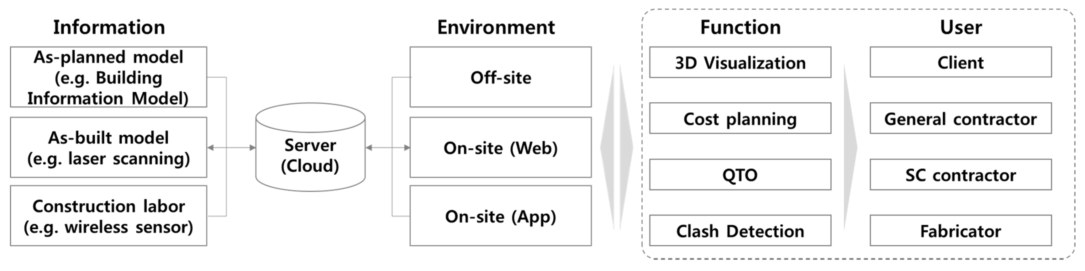
Figure 1 shows the proposed BIM-based construction management system framework from the perspective of SMEs, based on the research problem and theoretical considerations.
The system framework has the following features. First, it should be able to input and output various information (e.g., BIM model, wireless sensor data, laser scan, or image scan data). Even if the system only needs to manage the construction of a single process (e.g., steel frame construction), the as-planned model for the plan, the as-built model for the execution result, and the information about the construction labor can differ. Information on buildings can be obtained from the BIM Model and laser scan data, but that manpower needs to be collected using equipment, such as wireless sensors (e.g., safety helmets, safety vests, and safety shoes) [29]. Construction management and human resource management should be undertaken by utilizing this information. Second, from the viewpoint of SMEs, the system should only be equipped with the functions (e.g., 3D visualization, cost planning, quantity take-offs (QTOs), and clash detection) that are necessary for a BIM-based construction management system. It is necessary to supervise the construction progress while using this information and to establish accurate planning, input, and management of the workforce. Moreover, the system should be realistic, usable, and compatible in various system operating environments (e.g., Off-site and Web- and app-based on-site management environments). Third, the system must improve accessibility for all users in various formats (e.g., html, pdf, image, dwfx, etc.), which are typically used for the Web and apps. It should be possible to access the information that is necessary for construction management with smart device operation technology rather than the BIM software, which is difficult to access and operate.
3.2. Main Function Derivation for the System
We analyze a typical steel frame construction in order to derive the necessary functions for the system [35]. Table 4 summarizes the main work phases and tasks, the authorities that are responsible for each task, work location, and BIM usage in steel frame construction. For on-site and off-site steel frames constructions, BIM authoring creates the 3D model, visualizes the quality review, produces a shop drawing, conducts a 4D simulation for process management, and checks QTOs for cost management.
In the preconstruction phase, the drawings and specification reviews are used to check whether the design requirements are reflected and whether the object information that is related to the material and dimension of the steel frame is correctly entered. After reviewing the design information, a 2D steel frame shop drawing is extracted from the BIM model for factory production.
In the prefabrication phase, accurate quantity calculation data are used when ordering the steel material for frame member fabrication. In addition, the cutting work from the manufacturing process is numerically managed using the BIM model. As a result, it is possible to find not only the gross weight of the member, but also its net weight, excluding the cutting part. To minimize the loss of steel material, the BIM model can be used to efficiently cut the members. During this process, the installation of the steel frame is reviewed to reduce the work, and the site conditions, such as fabrication, transportation, lifting, and ease of installation, are considered. When the fabrication and inspection of the steel members are completed, the prefabricated steel members are procured on-site.
In the construction phase, the steel frame members that were procured from the factories are laid down when considering the order of installation. They are then temporarily assembled through steel bolting and welding. Thereafter, the construction is sequentially done using the shop drawing and 4D simulation. The installation procedure involves installing the column, large beam, small beam, and brace members.
3.3. Definition of System Database
3.3.1. Building Objects of Prefabricated Steel Frame
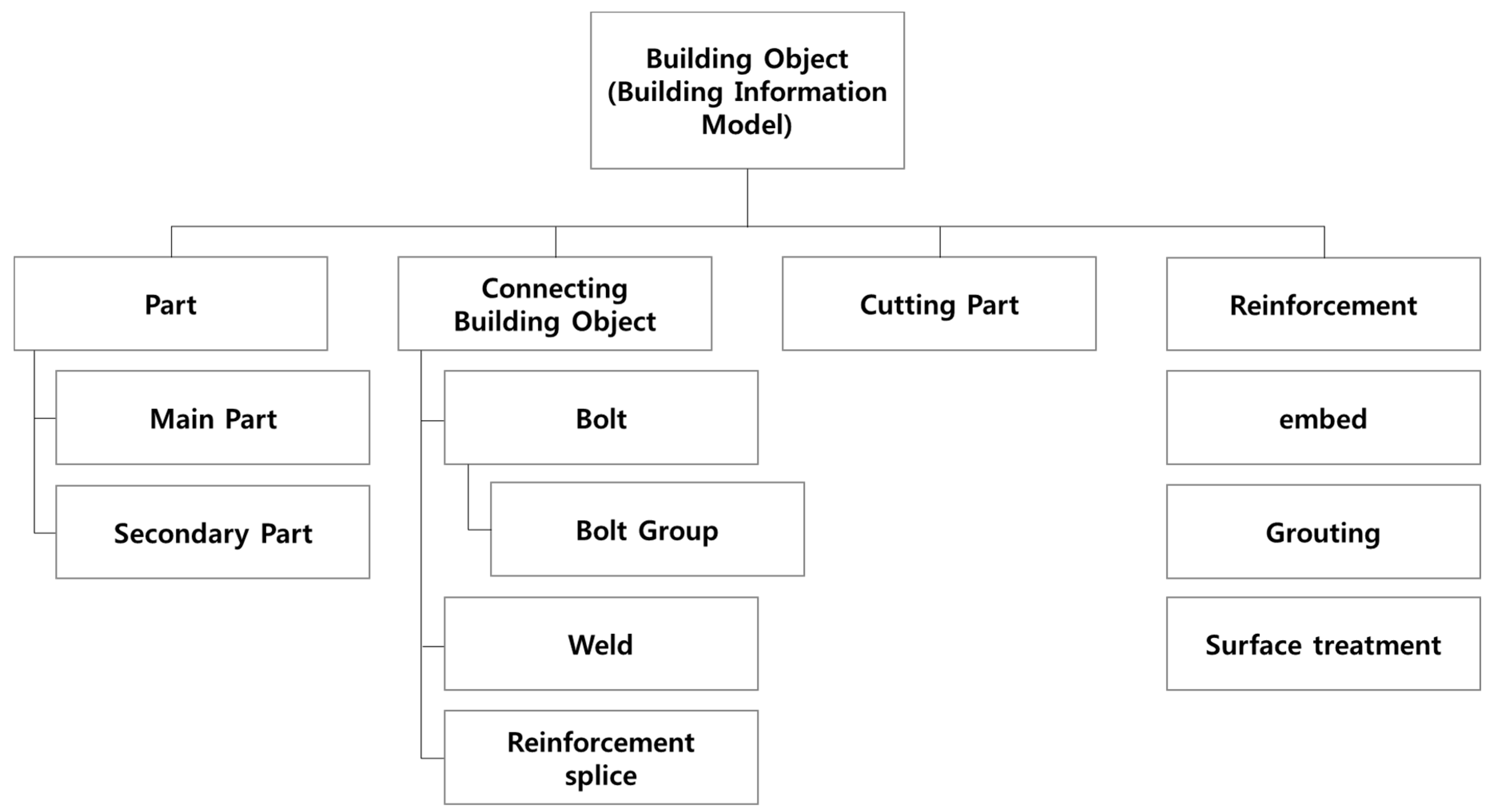
Figure 2 shows the objects that make up the BIM model of the prefabricated steel frame. The part that constitutes the prefabricated steel frame as per the BIM model is divided into the main part and the secondary part. Each part is automatically categorized with a number (double or int) or a string and stored as a BIM object. In addition, the bolts that are connected to the steel frame members and welded members are grouped, and the respective components are assembled. The number and dimensions of the holes for cutting and bolting the steel frame members are included [68].
3.3.2. Connecting Building Objects to Create a Prefabricated Steel Frame
Table 5 lists the numerical data regarding the BIM model of the steel frame joints for the case study project that is discussed in this paper. It shows the data structure of the connections of the steel frame parts, namely the main part, secondary part, and bolts, as well as welding lengths. The materials of the end plate and bolts and the hole types are stored as strings, whereas the size and dimension of the bolts, tolerance distance, and notch length are stored as the numerical values. The strings and numerical data can be utilized to numerically control the machines that are used to produce the steel frame members [70]. In addition, the integration of the components of each steel member results in the complete BIM model for the steel frame construction. It includes most of the building components that are used in the steel frame construction based on the attribute values of the steel members. The BIM model constructed using such an object-oriented modeling can be quickly and accurately modified if any changes to the design and/or information are made.
4. Effects of BIM-Based Construction Management System for SMEs
4.1. Case Study
4.1.1. Project Description
To analyze the effect of BIM on the prefabricated steel frame construction from an SME perspective, the project, as summarized in Table 6, is chosen. The total construction cost was less than ₩1 Bn and the total load acting on the prefabricated steel frame was 91.78 t. The design phase of this case study project was based on a 2D Computer-Aided Design (CAD) drawing.
The project client majored in architectural engineering and has worked as a BIM manager. Thus, the client is aware of the usefulness of the BIM model. However, the client does not have firsthand experience of the effect of BIM on actual projects. After interviewing the client, we found that the accuracy of the information regarding the quantity of prefabricated steel frame, which accounted for a large portion of the total construction cost, significantly influenced the decision-making process. Table 7 summarizes the total construction cost (of the three bidding projects), the prefabricated steel frame construction, and whether BIM was applied.
The specialty contractor (SC) used TEKLA to create a BIM model of the steel frame based on the design drawings for the general contractor (GC). Accordingly, we calculated the quantity of the major components required for the steel frame construction. Using this information, the GC calculated the material, labor, and overhead costs required to estimate the total construction cost. As for the other companies, the total construction cost was higher, and no information on the cost of steel frame construction, including material, labor, and overhead costs, was provided to the client. Therefore, the client selected the contractor who presented the lowest total construction cost with the exact quantities for steel construction.
The selected GC has 25 employees, with a capital of less than ₩1 Bn and a revenue of ₩14.6 Bn as of 2016. The SC, who is responsible for the steel frame construction, is engaged in the construction of steel frames and related structures, with a capital of ₩10 Mn and a revenue of ₩1,810.33 Mn as of 2015. The GC and SC are both SMEs.
4.1.2. Description of the BIM Model of a Prefabricated Steel Frame
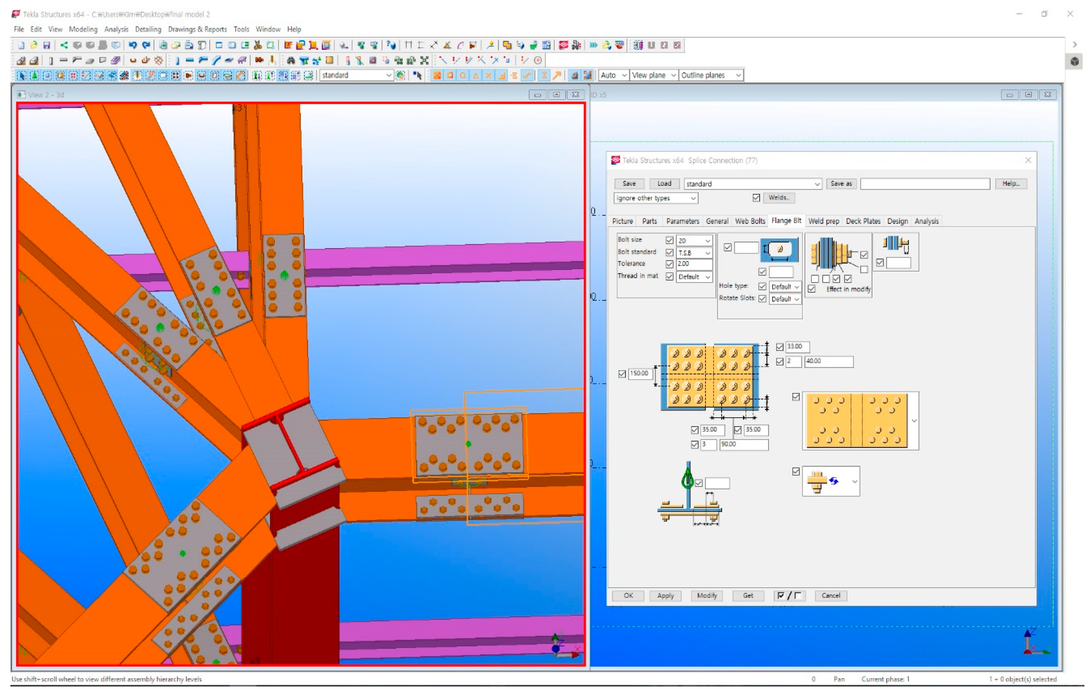
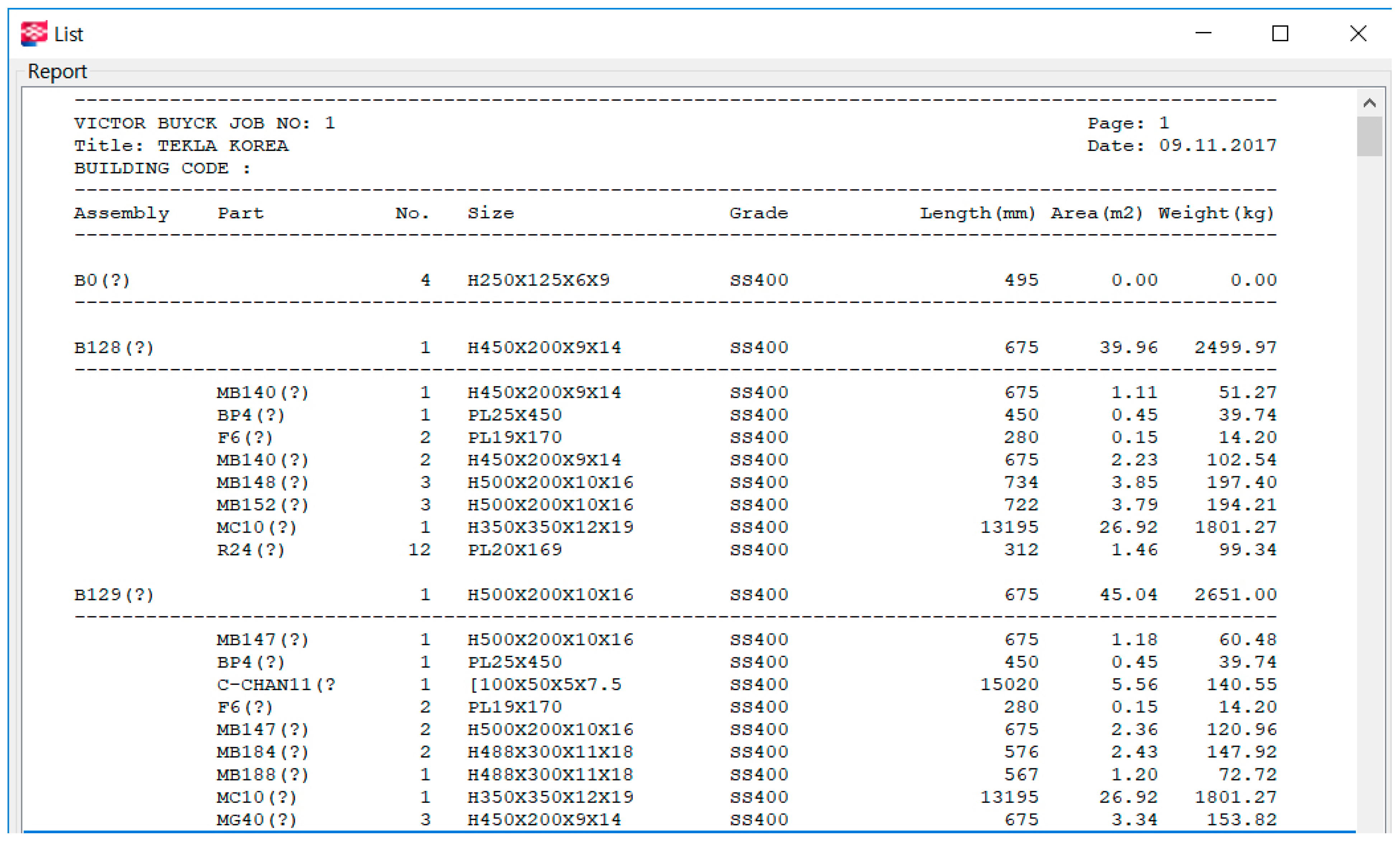
Figure 3 shows the main and secondary parts of the BIM model based on the contents of the case study that is shown in Figure 2. Figure 4 shows the BIM model, including the number of bolts, welding length, cutting parts, grouting, and surface treatment related to the steel joints. Based on these data, the standard, quantity, grade, area, weight, and unit weight of the steel members can be automatically calculated, as shown in Figure 5.
4.2. Effects of BIM-Based Construction Management System for SMEs in the Preconstruction Phase
4.2.1. Extraction of Fabrication Drawing
The BIM model of the prefabricated steel frame, which was developed before the construction, is used to create various shop drawings for factory construction. As listed in Table 7, the types of drawings are general arrangement (GA) drawings, which show information regarding the planes, elevations, and cross-sections; a single part drawing, which shows a single part without the welded parts, such as anchor bolts and plates; an assembly drawing, which contains information regarding the steel frame members; and, a cast unit drawing, which is used for the foundation and steel frame plinth. The design changes are automatically reflected in the shop drawings as the BIM model and shop drawings are created based on the objects, and they are linked by parameters. For this case study, a total of 107 detailed drawings were generated to construct the prefabricated steel frame from the BIM model (Table 8).
4.2.2. Review of Shop Drawing
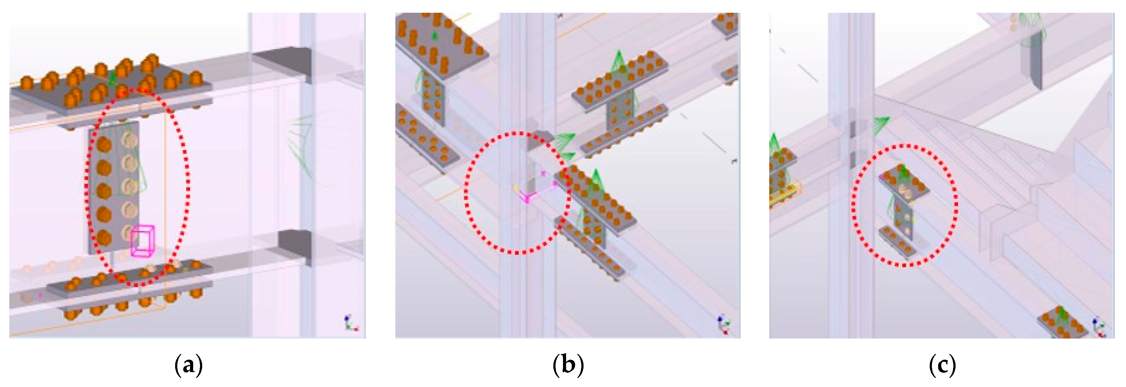
In the final phase, the BIM model was used to conduct a clash check before fabricating the members using the shop drawings. As a result, a total of 39 clashes occurred, which was similar to the ones shown in Figure 6. The clashes mainly occurred
- when steel frame members were crossed or penetrated,
- between the bolts and bolted plates, and
- between a steel part member and a steel plate member.
The members that were included in the clash check result can be classified into type, object ID, assembly ID, and object name. The members were modified prior to fabricating at the factory based on this information.
4.3. Effects of BIM-Based Construction Management System for SMEs in the Fabrication Phase
4.3.1. Prefabrication Review
In the fabrication phase, the necessary steel frame members should be accurately produced. Therefore, a fabrication review should be performed based on the information extracted from the BIM model. The following considerations are important in the manufacture of steel members:
- confirm whether it is easy to fabricate, transfer, lift, and field-install;
- confirm whether it contains additional steel frames for building the steel frames;
- check the welding position, welding method, and dimensions; and,
- check the size and shape of the steel frames.
The visual and quantity-related information regarding the unit steel frame members, including mark (Mark), specification (Description), quantity (Quantity), length (Length), material (Remark), and number of bolts, were extracted from the BIM model. Thus, the review could be performed smoothly. Table 9 lists the information required for steel frame fabrication.
4.3.2. Carrying Steel Frame Members from Off-Site to On-Site
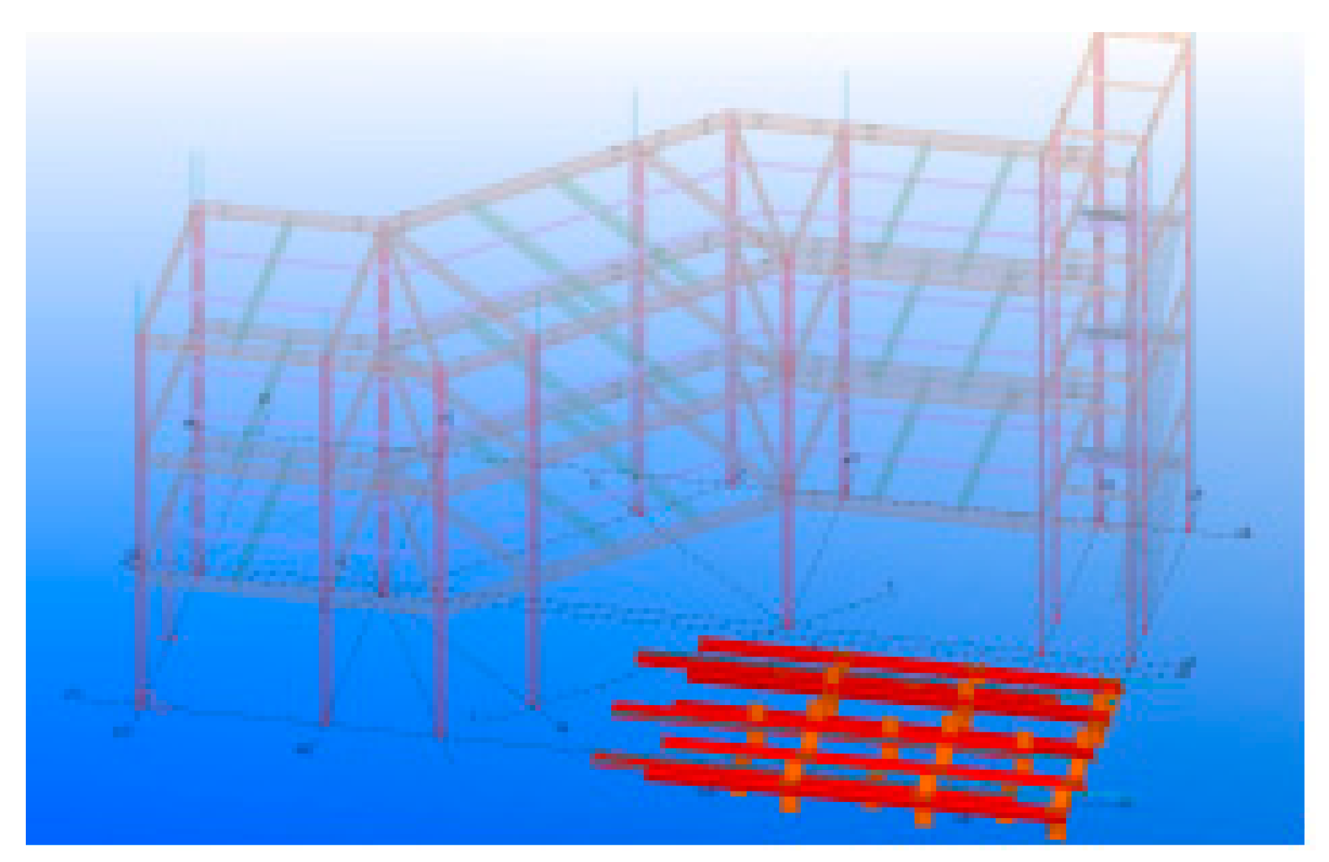
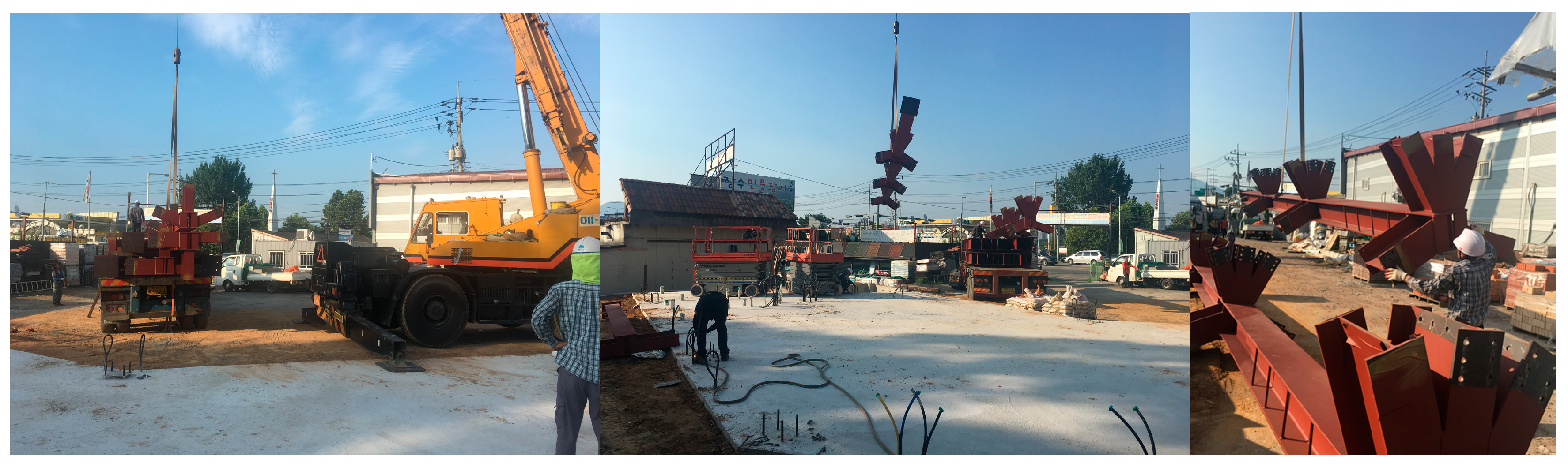
The length, width, volume restriction of vehicles, and entrance road conditions around the site should be considered based on the surrounding traffic situation when carrying the steel frame members to the site from the factory in the order of construction. Furthermore, the order in which the steel frame members are to be unloaded and their exact arrival times should be known to the site supervisors. With the BIM model, it is possible to simulate the position of the laydown area in advance, as shown in Figure 7, and to estimate the quantity, depending on the construction progress.
The BIM model helps construction companies and professional construction enterprises to efficiently lay the steel frame members by considering the type of construction. In addition, it is possible to minimize errors that may occur during the construction by accurately estimating the information regarding the steel frame members. Thus, the BIM model helps to save time and money, given that it optimizes the number of workers that are required in the field. In this project, the total weight of the steel frame members was approximately 92 t. It took two days (August 4th and 6th) to carry the steel frame members to the laydown area, as shown in Figure 8.
4.4. Effects of BIM-Based Construction Management System for SMEs in the Construction Phase
4.4.1. Integrated Management of Cost and Schedule
After the steel members are carried to the laydown area, the installation work begins by referring to the shop drawings. To manage the cost and schedule associated with the prefabricated steel frames, these aspects of the BIM model are integrated, as seen in Table 10. Given that the project was small-scale, the construction that was carried out during the period of August 4th, 2017 to August 9th, 2017 was selected for the study. On August 4th, 2017, the steel frame members were carried to the laydown area, and the anchor bolts were installed. Based on the information that was provided in the BIM model and shop drawings, the materials were carried in, and the next phase of the work was prepared. Regarding the equipment, one crane was used for the member laydown, with five people working on-site. On August 5th, the main processes comprised building the steel columns and non-shrink grouting, and the total weight of the installed steel frame was 31.46 t. On August 6th, the welded plates and the steel frame beam members were carried to the area, and the total weight of the installed frame was 15.36 t. A total of 91.78 t of steel frame members were installed by August 9th.
4.4.2. Quality Management Using BIM and Laser Scanning
The construction errors in this case study project were considerably low, because the construction was small-scale, and the pre- and post-processes had little effect on the prefabricated steel frame construction. The construction errors can be measured by comparing the BIM model, which is an as-planned and already constructed model, with a laser scanning equipment, which is an as-built model that is created by a construction company and a professional construction enterprise. Figure 9 shows the construction errors that were identified in the case study project using the BIM model and laser scanning equipment. The errors ranged from 16 to 70 mm in the web or flange direction of the steel frame member.
Although not found in this case study project, a large risk may arise if there is a significant error in the pre-installed steel frame members. If the reference steel frame member, which is assembled with many members, is twisted or severely tilted toward a specific direction, the construction of the steel frame materials, which need to be installed through subsequent works, can be considerably affected. The damages can be significant due to the increase in the construction cost and any delay in the construction from new member orders or additional fabrications, disposing of pre-order members, and duplicated fabrication of steel frame members. Therefore, an as-built model for the pre-process should be created while using the laser scanning technology, the BIM model should be reviewed, and the prefabrication should be implemented by reflecting the actual conditions of the site.
5. Discussion
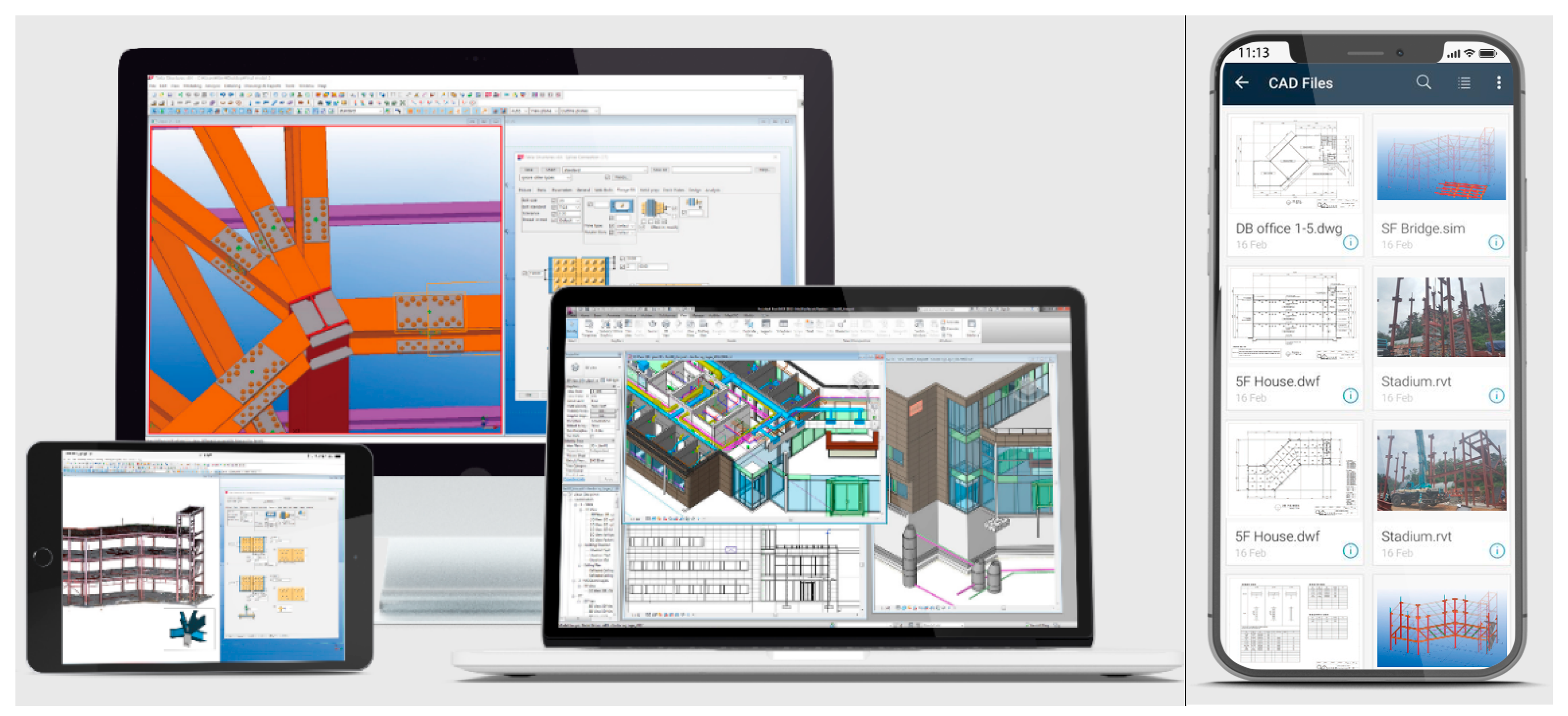
The features of the system framework described above are as follows: (1) capability to input and output various types of information, (2) the inclusion of only the necessary functions from the viewpoint of SMEs, and (3) improved accessibility, such that anyone may use the system online or with an app (Figure 10). Construction managers require access to detailed information on buildings, and clients need an environment that can utilize various types of reliable information to support decision-making.
In order to verify the effectiveness of the BIM-based construction management system framework that is proposed in this study, we interviewed three researchers (e.g., M-design, Hanyang University, Seoul National University of Science & Technology) who participated in the system development, and four participants (e.g., Client, GC, and SC) who implemented the case project. Table 11 shows the expected effects of applying the system according to the information that was provided during the interviews.
It is difficult to ensure the reliability of results that are only based on data from interviews with research groups and project groups participating in small-scale projects. Therefore, we also conducted an end-user computing satisfaction (EUCS) survey. The evaluation of the information system under development was based on five factors (Content, Accuracy, Format, Ease of Use, and Timeliness) and 12 indicators (Table 3). The survey covered the potential users of the system under development, namely 40 BIM experts, including architects, construction, construction, and the BIM consultant, all of whom have more than three years of experience in using BIM. The questionnaire was completed by 26 people. Table 12 shows the results of the survey.
The results of the analysis indicate that the satisfaction levels with regard to the content and accuracy categories were relatively high. This is because the system under development is based on the database (DB) of commercial BIM software (SW). Since the information that is needed for the task is extracted from the BIM model, the reliability of the information content and accuracy is ensured. On the other hand, the satisfaction levels for the ease of use and timeliness categories were relatively low. These results suggest that the pre-service training of the system to be developed is necessary from the perspective of SMEs. In addition, additional expert assistance is needed for tasks that involve a high degree of difficulty. We need to carefully consider user experience and user interface when considering the fact that the system should be usable on the Web and via an app. Finally, the survey results indicated that the format of the system should be improved in conjunction with ease of use and timeliness. The proposed BIM-based construction management system framework can then effectively contribute to improving the work productivity, as well as the cost effectiveness of the project unit from the viewpoint of SMEs. In order to avoid construction risks, such as rising labor costs in Korea, SMEs can utilize this system framework as a technology strategy to combat the rising trend of relatively low wages paid to overseas construction laborers (e.g., those from Vietnam).
6. Conclusions
In this paper, we analyzed the BIM-based construction effect from the perspective of SMEs. The main research results of the study are summarized, as follows. First, the BIM-based Construction Management System Framework was conceptually proposed from the viewpoint of SMEs to improve the reliability of analysis. Second, detailed work analysis of the steel frame construction was conducted to derive the main functions of the system. Through this, we derived the application areas of BIM that can be used step-by-step. Third, we analyzed the BIM-based construction effect through the case project of SMEs. We analyzed the effects of BIM on SMEs stakeholders and system development researchers. The case study analyzed the effects of BIM application on the preconstruction, fabrication, and construction phases. The fabrication documents were extracted from the BIM model, and a clash detection review process in the preconstruction phase reviews the quality of the fabrication documents. In the fabrication phase, the information in the fabrication documents was checked before the prefabrication. Furthermore, the process of carrying the steel frame members to the site was reviewed by considering the surrounding buildings and the available space, and the approximate location of the laydown area was confirmed. In the construction phase, the cost and schedule were linked based on the BIM model, such that the construction of the building could be requested by the building owner based on quantitative data depending on the construction progress. After the construction was completed, comparing the BIM model with the measurements that were performed with laser scanning equipment could control the quality. Most SMEs working on construction projects obtain qualitative results when the BIM is applied to a specific work process in the preconstruction, fabrication, and construction phases. Fourth, the end user’s satisfaction with the system function was investigated to supplement the qualitative analysis result. In order to overcome the limitations of the single case analysis that was performed in this study, a EUCS survey was conducted among potential system users. The results of the analysis confirmed the direction for system development and improvement. In the future, we plan to analyze the effect of BIM application on structures other than steel frames (e.g., mechanical, electrical, and plumbing engineering) from the perspective of SMEs.
Author Contributions
Conceptualization, M.Y. and J.K.; methodology, M.Y. and J.K.; validation, M.Y., J.K. and C.C.; formal analysis, M.Y.; investigation, M.Y.; resources, M.Y.; data curation, M.Y.; writing—original draft preparation, M.Y. and J.K.; writing—review and editing, M.Y., J.K. and C.C.; visualization, M.Y.; supervision, M.Y.; funding acquisition, M.Y.
Funding
This work (Grant No. C0505520) was supported by the Business for Cooperative R&D between Industry, Academy, and Research Institute funded by the Korea Small and Medium Business Administration in 2019.
Conflicts of Interest
The authors declare that there are no conflicts of interest regarding the publication of this paper.
Data Availability
Data generated or analyzed during the study are available from the corresponding author upon request.
References
- Cheng, J.C.P.; Won, J.; Das, M. Construction and demolition waste management using BIM technology. In Proceedings of the 23rd Annual Conference of the International Group for Lean Construction, Perth, Australia, 29–31 July 2015. [Google Scholar]
- Sacks, R.; Eastman, C.; Lee, G.; Teicholz, P. BIM Handbook: A Guide to Building Information Modeling for Owners, Designers, Engineers, Contractors, and Facility Managers, 3rd ed.; Wiley: Hoboken, NJ, USA, 2018. [Google Scholar]
- Rajendran, P.; Gomez, C.P. Implementing BIM for waste minimisation in the construction industry: A literature review. In Proceedings of the 2nd International Conference on Management, Langkawi Kedah, Malaysia, 11–12 June 2012. [Google Scholar]
- Ahankoob, A.; Khoshnava, S.M.; Rostami, R.; Preece, C. BIM perspectives on construction waste reduction. In Proceedings of the Management in Construction Research Association (MiCRA), Langkawi Kedah, Malaysia, 5–6 December 2012. [Google Scholar]
- Anumba, C.; Dubler, C.; Goodman, S.; Kasprzak, C.; Kreider, R.; Messner, J.; Saluja, C.; Zikic, N. The BIM project execution planning guide and templates—Version 2.0. CIC Research Group, Department of Architectural Engineering, the Pennsylvania State University, University Park, PA, USA. 2010. Available online: https://www.bim.psu.edu/ (accessed on 12 January 2019).
- Williams, M. Building-information Modeling Improves Efficiency, Reduces Need for Changes. Bus. J. 2011. Available online: http://www.bizjournals.com/louisville/print-edition/2011/07/08/building-information-modeling-improves.html (accessed on 17 March 2017).
- Ham, N.; Lee, S. Project benefits of digital fabrication in irregular-shaped buildings. Adv. Civil Eng. 2019, 2019, 1–14. [Google Scholar] [CrossRef]
- Hamid, M.; Tolba, O.; El Antably, A. BIM semantics for digital fabrication: A knowledge-based approach. Autom. Constr. 2018, 91, 62–82. [Google Scholar] [CrossRef]
- Zhang, J.P.; Hu, Z.Z. BIM- and 4D-based integrated solution of analysis and management for conflicts and structural safety problems during construction: 1. Principles and methodologies. Autom. Constr. 2011, 20, 155–166. [Google Scholar] [CrossRef]
- Bryde, D.; Broquetas, M.; Volm, J.M. The project benefits of building information modelling (BIM). Int. J. Project Manag. 2013, 31, 971–980. [Google Scholar] [CrossRef]
- Lee, G.; Park, K.H.; Won, J. D3 city project—Economic impact of BIM-assisted design validation. Autom. Constr. 2012, 22, 577–586. [Google Scholar] [CrossRef]
- Kim, S.; Chin, S.; Han, J.; Choi, C.H. Measurement of construction BIM value based on a case study of a large-scale building project. J. Manag. Eng. 2017, 33, 05017005. [Google Scholar] [CrossRef]
- Ham, N.; Moon, S.; Kim, J.H.; Kim, J.J. Economic analysis of design errors in BIM-based high-rise construction projects: Case study of Haeundae L Project. J. Constr. Eng. Manag. 2018, 144, 05018006. [Google Scholar] [CrossRef]
- Hong, Y.; Hammad, A.W.A.; Sepasgozar, S.; Akbarnezhad, A. BIM adoption model for small and medium construction organisations in Australia. Eng. Constr. Archit. Manag. 2018, 26, 154–183. [Google Scholar] [CrossRef]
- Hosseini, M.R.; Banihashemi, S.; Chileshe, N.; Namzadi, M.O.; Udeaja, C.E.; Rameezdeen, R.; McCuen, T. BIM adoption within Australian small and medium sized enterprises (SMEs): An innovation diffusion model. Constr. Econ. Build. 2016, 16, 71–86. [Google Scholar] [CrossRef]
- Dainty, A.R.J.; Leiringer, R.; Fernie, S.; Harty, C. BIM and the small construction firm: A critical perspective. Build. Res. Inf. 2017, 45, 696–709. [Google Scholar] [CrossRef]
- Lam, T.T.; Mahdjoubi, L.; Mason, J. A framework to assist in the analysis of risks and rewards of adopting BIM for SMEs in the UK. J. Civ. Eng. Manag. 2017, 23, 740–752. [Google Scholar] [CrossRef]
- Ghaffarianhoseini, A.; Doan, D.T.; Zhang, T.; Ur Rehman, A.; Amirhosein, G.; Nicola, N.; John, T. A BIM readiness & implementation strategy for SME construction companies in the UK. In Proceedings of the 33rd CIB W78 Conference 2016, Brisbane, Australia, 31 October–2 November 2016. [Google Scholar]
- Jernigan, F.E. BIG BIM Little BIM: The Practical Approach to Building Information Modeling-Integrated Practice Done the Right Way! 4Site Press: Salisbury, MD, USA, 2008. [Google Scholar]
- Erin, R.H. Achieving strategic ROI, measuring the value of BIM, in: Is it time for BIM? Achieving strategic ROI in your firm, Autodesk. 2016. Available online: https://damassets.autodesk.net/content/dam/autodesk/www/solutions/pdf/Is-it-Time-for-BIM-Achieving-Strategic-ROI-in-Your-Firm%20_ebook_BIM_fin al_200.pdf (accessed on 5 March 2017).
- Mark, R. SMEs: The key to the construction sector’s future. Latest News, Scape Group. 2017. Available online: https://www.scapegroup.co.uk/news/2017/smes-the-key-to-the-construction-sectors-future (accessed on 2 September 2017).
- National Statistics. Business Population Estimates 2017: Annual Business Population Estimates for the UK and Regions in 2017. Includes Revised Totals for 2013 to 2016, Taking Account of Updated Source Data; Department for Business, Energy & Industrial Strategy: London, UK, 2017.
- Department for Business, Enterprise and Regulatory Reform (BERR) (2006), SME STATISTICS 2006, BERR: Enterprise Directorate Analytical Unit. Available online: http://stats.berr.gov.uk/ed/sme/ (accessed on 22 January 2019).
- Lu, S.L.; Sexton, M.G.; Abbot, C. Key characteristics of small construction firms: A United Kingdom perspective. In Proceedings of the CIB W065/055 Commissions: Transformation through Construction, Dubai, UAE, 15–17 November 2008; Available online: https://www.irbnet.de/daten/iconda/CIB17619.pdf (accessed on 17 February 2019).
- Curran, J.; Blackburn, R.A. Researching the Small Enterprise, 1st ed.; Sage Publications: London, UK, 2001. [Google Scholar]
- Robinson, R.B., Jr.; Pearce, J.A. Research thrusts in small firm strategic planning. Acad. Manag. Rev. 1984, 9, 128–137. [Google Scholar] [CrossRef]
- Lu, S.; Sexton, M. Innovation in small construction knowledge-intensive professional service firms: A case study of an architectural practice. Constr. Manag. Econ. 2006, 24, 1269–1282. [Google Scholar] [CrossRef]
- Sexton, M.; Barrett, P. Appropriate innovation in small construction firms. J. Constr. Manag. Econ. 2003, 21, 623–633. [Google Scholar] [CrossRef]
- Yoo, M.; Choi, C.; Yoo, S.; Park, S. Communication performance of BLE-based IoT devices and routers for tracking indoor construction resources. IJIBC 2019, 11, 27–38. [Google Scholar] [CrossRef]
- Alsafouri, S.; Ayer, S.K. Review of ICT implementations for facilitating information flow between virtual models and construction project sites. Automat. Constr. 2018, 86, 176–189. [Google Scholar] [CrossRef]
- Singh, V.; Gu, N.; Wang, X. A theoretical framework of a BIM-based multi-disciplinary collaboration platform. Automat. Constr. 2011, 20, 134–144. [Google Scholar] [CrossRef]
- Suh, S.W.; Yoon, Y.S.; Kim, S.K. The Development of Schedule Risk Management Tools at the Preconstruction Phase in Building Construction-Focused on the Steel Work. J. Constr. Eng. Manag. 2005, 6, 177–185. [Google Scholar]
- Lim, C.H. Application of 3D information to reduce rework in a steel structure construction. Master’s Thesis, Hanyang University, Seoul, Korea, 2017. [Google Scholar]
- Jung, S.J. Building Construction - Construction of Steel Structure; Kimoondang: Seoul, Korea, 2013; ISBN 9788962255331. [Google Scholar]
- Kim, Y.H.; Lee, J.S.; Oh, J.K.; Kim, J.J. A study for derivation of participant’s information flow at framework construction based on BIM. Korea J. Constr. Eng. Manag. 2013, 14, 22–34. [Google Scholar] [CrossRef]
- Park, C.S.; Park, H.T. Improving contractibility analysis tasks by applying BIM technology. Korea J. Constr. Eng. Manag. 2010, 11, 137–146. [Google Scholar] [CrossRef]
- Eom, J.U.; Shin, T.S. A study on the automation of the connection modeling for steel structures based on BIM. J. Korean Soc. Steel Constr. 2010, 22, 99–108. [Google Scholar]
- Ko, A.R.; Lee, S.I.; Cho, Y.S. Development of automatic design system for steel connection based on S-BIM. Korea J. Constr. Eng. Manag. 2013, 29, 21–28. [Google Scholar]
- Eom, J.U.; Shin, T.S. A development of interface module between structural design and detail design based on BIM. J. Korean Soc. Steel Constr. 2011, 23, 113–124. [Google Scholar]
- Li, K.; Gan, Y.; Ke, G.; Chen, Z. The Analysis and Application of BIM Technology in Design of Steel Structure Joints. In Proceedings of the 4th International Conference on Sensors, Measurement and Intelligent Materials (ICSMIM 2015), Shenzhen, China, 27–28 December 2015; pp. 1166–1171. [Google Scholar]
- Oti, A.H.; Tizani, W. BIM extension for the sustainability appraisal of conceptual steel design. Adv. Eng. Inform. 2015, 29, 28–46. [Google Scholar] [CrossRef] [Green Version]
- Ryu, J.S.; Kim, K.H. A study of 4D simulation system using automatic scheduling process-The focus on steel structural construction. J. Architectural Inst. Korea 2009, 25, 173–180. [Google Scholar]
- Yun, S.H.; Park, C.W.; Lee, G.; Bongkeun, K. A study on a method for tracking lifting paths of a tower crane using GPS in the BIM environment. J. Architectural Inst. Korea 2008, 24, 163–170. [Google Scholar]
- Shin, T.S.; Yang, J. A proposal for the automation process of creating shop drawings in steel constructions. J. Architectural Inst. Korea 2009, 11, 267–274. [Google Scholar]
- Kim, K.T. A study on the application of RTLS technology for the automation of spray-applied fire resistive covering work. J. Korea Inst. Build. Constr. 2009, 9, 79–86. [Google Scholar] [CrossRef]
- Xie, H.; Shi, W.; Issa, R.R.A. Using RFID and real-time virtual reality simulation for optimization in steel construction. J. Inf. Technol. Constr. 2011, 16, 291–308. [Google Scholar]
- Liu, W.; Guo, H.; Li, H.; Li, Y. Using BIM to improve the design and construction of bridge projects: A case study of a long-span steel-box arch bridge project. Int. J. Adv. Robot. Syst. 2014, 11, 125. [Google Scholar] [CrossRef]
- Ginzberg, M.J.; Zmud, R.W. Evolving Criteria for Information Systems Assessment. In Proceedings of the IFIP WG 8.2 Working Conference, San Francisco State University, San Francisco, CA, USA, 11–12 December 1987. [Google Scholar]
- Will, P.; Olson, M.H. Managing investment in information technology: Mini case examples and implication. MIS Q. 1989, 13, 3–17. [Google Scholar] [CrossRef]
- Benjamin, R.I.; Rockart, J.F.; Wyman, S.M.J. Information technology: A strategic opportunity. Sloan Manag. Rev. 1984, 25, 3–14. [Google Scholar]
- Joan, S. IT Performance Measurement: A Discussion Paper on Measurement Practices. Available online: www.gsa.itpolicy.gov (accessed on 14 December 2018).
- Shannon, C.E.; Weaver, W. The Mathematical Theory of Communication; University of Illinois Press: Urbana, IL, USA, 1949. [Google Scholar]
- Mason, R.O. Measuring information output: A communication systems approach. Inform. Manag. 1978, 1, 219–234. [Google Scholar] [CrossRef]
- Delone, W.H.; Mclean, E.R. Information systems success: The quest for the dependent variable. Inf. Syst. Res. 1992, 3, 66–95. [Google Scholar] [CrossRef]
- Lucas, H.C., Jr.; Henry, C. Evolution of An Information System: From Keyman to Every Person. Sloan Manag. Rev. 1978, 19, 39–55. [Google Scholar]
- Hamilton, S.; Chervany, N.L. Evaluating information system effectiveness—Part I: Comparing evaluation approaches. MIS Q. 1981, 5, 55–69. [Google Scholar] [CrossRef]
- Saarineen, T. An expanded instrument for evaluating information system success. Inform. Manag. 1996, 31, 103–118. [Google Scholar] [CrossRef]
- Bailey, J.; Pearson, S. Development of a tool for measuring and analyzing computer user satisfaction. Manag. Sci. 1983, 29, 530–545. [Google Scholar] [CrossRef]
- Miller, J.; Doyle, B.A. Measuring the effectiveness of computer-based information systems in the financial services sector. MIS Q. 1987, 11, 107–124. [Google Scholar] [CrossRef]
- Kim, J.S.; Cho, Y.B.; Kim, Y.I. A study on factor analysis for successful informatization of SMEs. KMIS 1994, 1994, 129–163. [Google Scholar]
- Jung, K.E.; Lee, D.M. Reciprocal effect of the factors influencing the satisfaction of IS users. Asia Pac. J. Inf. Syst. 1995, 5, 199–226. [Google Scholar]
- Suh, K.S. A study on the factors affecting the success of end-user computing. APJIS 1995, 5, 259–288. [Google Scholar]
- Lves, B.; Olson, M.H.; Baroudi, J.J. The measurement of user information satisfaction. Commun. ACM 1983, 26, 785–793. [Google Scholar] [Green Version]
- Doll, W.J.; Torkzadeh, G. The management of end-user computing satisfaction. MIS Q. 1988, 12, 259–274. [Google Scholar] [CrossRef]
- Doll, W.J.; Xia, W. Confirmatory factor analysis of the end-user computing satisfaction instrument: A replication. JUEC. 1994, 9, 24–31. [Google Scholar] [CrossRef]
- Kim, S.; McHaney, R. Validation of the end-user computing satisfaction instrument in case tool environments. J. Comput. Inform. Syst. 2000, 41, 49–55. [Google Scholar]
- Hendrickson, A.R.; Glorfeld, K. On the repeated test-retest reliability of the end-user computing satisfaction instrument. Decis. Sci. 1994, 25, 655–667. [Google Scholar]
- AEC Magazine. Tekla Structure 19. 2013. Available online: http://www.aecmag. com/software-mainmenu-32/563-tekla-structures-19 (accessed on 2 February 2019).
- Kim, J.; Yoo, M.; Ham, N.; Kim, J.; Choi, C. Process of Using BIM for Small-Scale Construction Projects - Focusing on the Steel-frame Work. KIBIM Mag. 2018, 8, 41–50. [Google Scholar]
- Robinson, C. Structural BIM: Discussion, case studies and latest developments. Struct. Des. Tall Spec. Build. 2007, 16, 519–533. [Google Scholar] [CrossRef]
Figure 1.
Conceptual diagram of BIM-based construction.

Figure 2.
Building objects of the BIM model [69].
Figure 2.
Building objects of the BIM model [69].

Figure 3.
BIM model of a prefabricated steel frame.
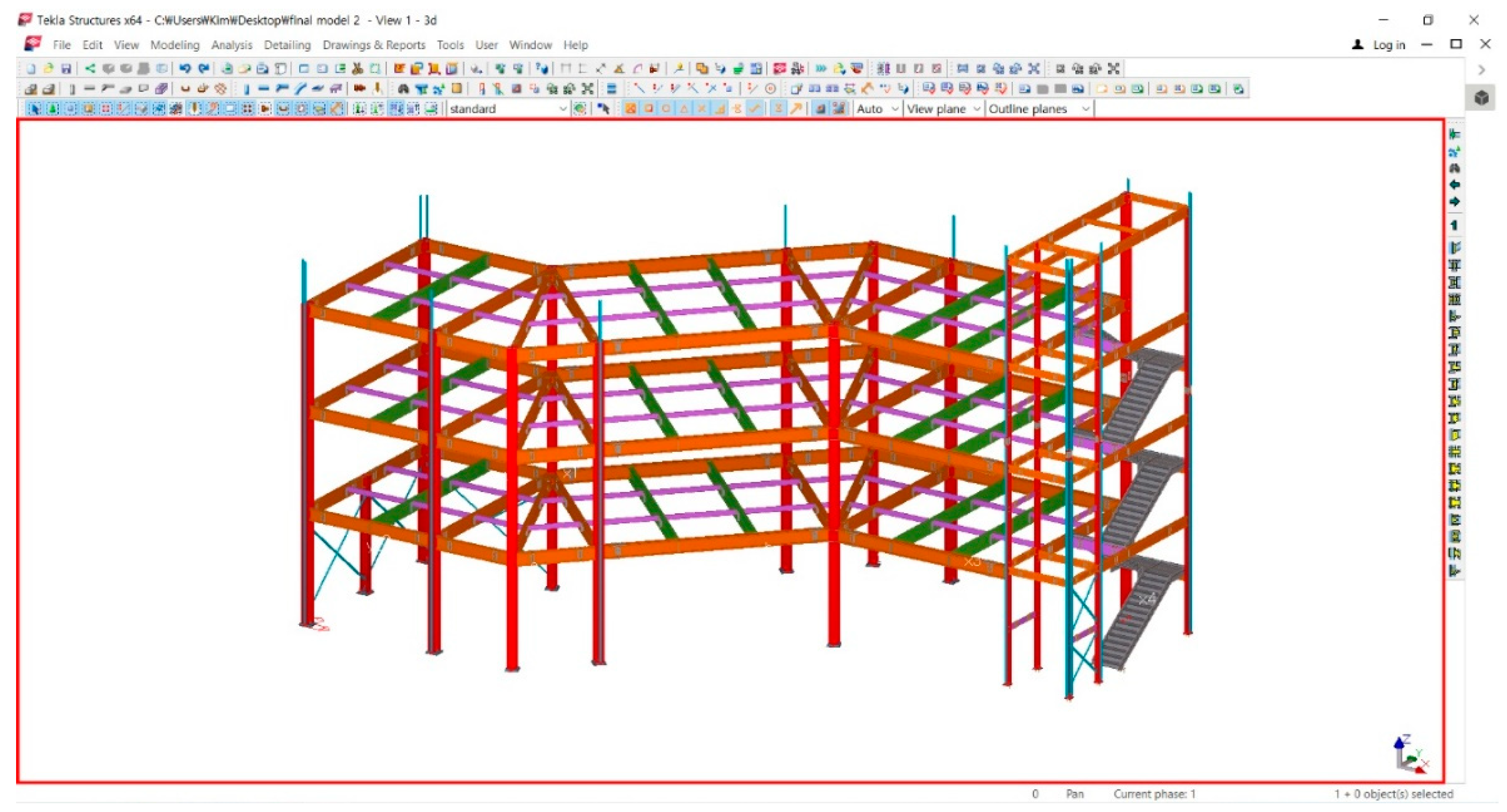
Figure 4.
Detailed information regarding the joints of the steel frame members.

Figure 5.
Information regarding the quantities of the steel frame members.

Figure 6.
Clash check step applied to the BIM model: (a) Steel part members and bolts; (b) Steel part members and steel plate members; and, (c) Steel part members and stairs.
Figure 6.
Clash check step applied to the BIM model: (a) Steel part members and bolts; (b) Steel part members and steel plate members; and, (c) Steel part members and stairs.

Figure 7.
Preliminary review of building and member laydown area.

Figure 8.
Transportation of the steel frame members to the laydown area.

Figure 9.
Column construction deviation.
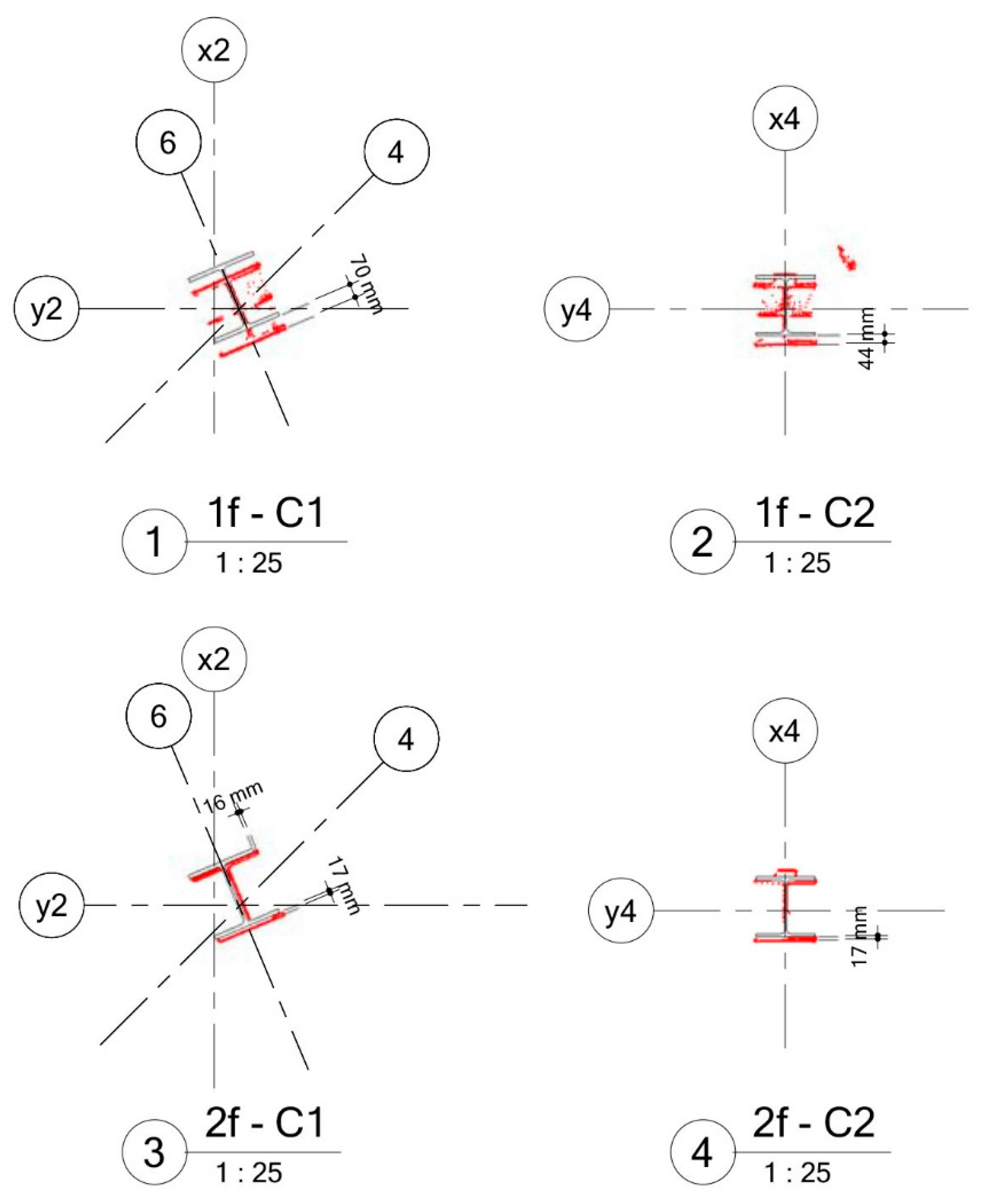
Figure 10.
Web and app-based operational samples using the proposed system.


Table 1.
Functions and effects of building information modeling (BIM).
| BIM Function | Effect of BIM | Phase |
|---|---|---|
| 3D BIM conversion design | - Create object information through 3D modeling - Improved drawing consistency | Design/Construction |
| Visualization | - Improved understanding of work scope and tasks through improved communication - Design suitability review and VE enhancement function | Design/Construction |
| Linking through object base | - Automation of design changes - Prevention of drawing errors and notation omissions | Design/Construction |
| Clash check | - Enabling advance production of members through accurate drawings - Reduced field work and construction period and increased productivity | Design/Construction |
| 2D drawing creation | - Design, construction, and automatic extraction of tender drawings - Reduced field work and construction period and increased productivity | Design/Construction |
| Quantity calculation and estimation | - Quantity calculation and utilization depending on the part type, construction type, and phase - 4D + Cost = 5D (Estimate analysis) | Design/Construction |
| 4D simulation | - Creation of schedule, material, and allocation plans for personnel - 3D + Time = 4D (Process analysis) | Design/Construction |
| Temporary work and construction management | - Transfer of equipment, material transfer and loading path, operator working path planning, and pre-work coordination with equipment operator(s) | Construction |
| Combination with various analyses | - Analysis of energy efficiency, structural analysis, and Leadership in Energy and Environmental Design (LEED) analysis | Design |
Table 2.
Research highlights of previous studies that studied BIM for steel frame construction.
| Category | Researcher/s (Year) | Research Content |
|---|---|---|
| Design | Eom and Shin [37] | Development of an automation module for modeling steel frame joints that can be used in structural detail design and modeling stages |
| Ko et al. [38] | Development of an automatic design system for steel connections based on set-based Design with structural building information modeling (S-BIM) | |
| Eom and Shin [39] | Development of an interface module that can exchange information between structural analysis software supporting structural design work and BIM software supporting detailed modeling and drawing work | |
| Li et al. [40] | Description of a modeling system for steel structure joints based of BIM at the design stage | |
| Oti and Tizani [41] | Introduction of a BIM-based structural sustainability appraisal system | |
| Construction | Ryu and Kim [42] | Development of a 4D simulation system prototype through automatic-process production |
| Yun et al. [43] | Development of a tracking method for lifting paths of a steel frame tower crane using global positioning system (GPS) in the BIM environment | |
| Shin and Yang [44] | Development of a smart creation process for shop drawings depending on drawing types | |
| Kim [45] | Application of real-time locating system (RTLS) technology for automating spray-applied fire-resistive covering work | |
| Xie et al. [46] | Using radio-frequency identification and real-time virtual reality simulation for optimization in steel construction | |
| Liu et al. [47] | Using BIM to improve the design and construction of bridge projects |
Table 3.
Evaluation index for measuring End-User Computing Satisfaction (EUCS).
| Category | Evaluation Index | Contents of Evaluation Index |
|---|---|---|
| Content | C1 | Does the system provide the precise information you need? |
| C2 | Does the information content meet your need? | |
| C3 | Does the system provide reports that seem to be just about exactly what you need? | |
| C4 | Does the system provide sufficient information? | |
| Accuracy | A1 | Is the system accurate? |
| A2 | Are you satisfied with the accuracy of the system? | |
| Format | F1 | Do you think the output is presented in a useful format? |
| F2 | Is the information clear? | |
| Ease of Use | E1 | Is the system user friendly? |
| E2 | Is the system easy to use? | |
| Timeliness | T1 | Do you get the information you need in time? |
| T2 | Does the system provide up-to-date information? |
Table 4.
Main tasks involved in steel frame construction and BIM use mapping.
| Phase | Task | Authority | Location | BIM Use |
|---|---|---|---|---|
| Preconstruction | - Drawing and specification review | GC/SC * | On-site | - |
| - Construction planning | GC/SC | On-site | Visualization, 4D simulation | |
| - Shop drawing | GC/SC | On-site | Creation of 2D shop drawings | |
| - Cross check | GC/SC | On-site | Visualization, clash check | |
| Prefabrication | - Bringing steel framing members and reviewing the quantity | GC/SC | Off-site | Quantity calculation |
| - Steel frame cutting | GC/SC | Off-site | Creation of 2D drawings (cutting plan) | |
| - Steel frame mounting | GC/SC | Off-site | - | |
| - Steel frame assembly and welding | GC/SC | Off-site | Quantity calculation | |
| - Painting steel frame members | GC/SC | Off-site | Quantity calculation | |
| - Marking | GC/SC | Off-site | 3D BIM authoring | |
| - Precision inspection | GC/SC | Off-site | Visualization (e.g., laser scanning) | |
| - Carrying steel frame on and off the site | GC/SC | Off-site | Quantity calculation | |
| Construction | - Review of quantity brought to a laydown area | GC/SC | On-site | Quantity calculation |
| - Building and installing steel frame columns | GC/SC | On-site | Visualization, temporary works, and construction management | |
| - Steel girder, beam lifting, and installation | GC/SC | On-site | Temporary works and construction management | |
| - Vertical and horizontal inspection of the steel | GC/SC | On-site | Visualization (e.g., laser scanning) | |
| - Bolting and welding of the steel | GC/SC | On-site | Quantity calculation | |
| - Fireproof coating spray on steel | GC/SC | On-site | Quantity calculation | |
| - Steel frame installation finish (fastening) | GC/SC | On-site | Quantity calculation |
*: GC and SC denote general contractor and specialty contractor, respectively
Table 5.
Connecting building objects to create a prefabricated steel frame.
| Figure | Input | Attribute | Value | Type | |
|---|---|---|---|---|---|
 | End plate (a) | Material | mat | S275JR | string |
| Thickness | tpl1 | 10 | double | ||
| Depth | hpl1 | 200 | double | ||
| Width | bpl1 | 180 | double | ||
| Bolt (c) | Diameter | diameter | 20 | double | |
| Grade | screw | 7990 | string | ||
| lbd | 60 | string | |||
| lwd | 67.1 | string | |||
| lba | 66 | double | |||
| nb | 3 | int | |||
| nw | 2 | int | |||
| rb1 | 40 | double | |||
| rb2 | 40 | double | |||
| rw1 | 40 | double | |||
| rw2 | 40 | double | |||
| lbtyp | 1 | int | |||
| Weld (b) | w3_size | 6 | double | ||
| Notch (d) | t_cut_length | 82 | double | ||
| t_cope_length | 26 | double | |||
| b_cut_length | 82 | double | |||
| b_cope_length | 26 | double | |||
| cope_fitting_type | 3 | int | |||
Table 6.
Overview of the case study project.
| Item | Description |
|---|---|
| Project name | Neighborhood residence facilities construction |
| Location | Gyeonggi-do Namyangju-si Sampae-dong 153-7 |
| Main structure | Steel structure |
| Construction duration | 04/12/2017–10/31/2017 |
| Total Cost (₩) | 761,406,020 |
| Quantity of prefabricated steel frame | 91.78 t |
| Building coverage | 294.00 m2 |
Table 7.
Comparative analysis for general contractor/ specialty contractor (GC/SC) who participated in the case study project bidding.
Table 7.
Comparative analysis for general contractor/ specialty contractor (GC/SC) who participated in the case study project bidding.
| Item of Comparison | GC/Specialty Contractor 1 (Selected) | GC/Specialty Contractor 2 | GC/Specialty Contractor 3 |
|---|---|---|---|
| Total construction cost (₩) | 761,406,020 (VAT included) | 818,840,000 (VAT included) | 1,017,514,000 (VAT included) |
| Prefabricated steel frame construction (₩) | 161,406,202 | 155,700,000 | 253,658,750 |
| Quantity of prefabricated steel frame (t) | 91.78 | - (No information on quantity) | 105.13 (Lack of information on the quantity calculation) |
| Material, labor, and overhead costs | Constructed based on steel billets | Missing information | Missing information |
| Whether BIM was applied | Yes | No | No |
| BIM Software | TEKLA | - | - |
Table 8.
Drawing list.
| Drawing | Name | Quantity (Unit, EA) |
|---|---|---|
| General arrangement drawings | Block plan drawing, ground plan drawing, elevation drawing, cross-sectional drawing, and window and door drawing | 24 |
| Shop drawing | General arrangement drawing | 13 |
| Single part drawing | 20 | |
| Assembly drawing | 71 | |
| Others (anchor detail and 3D) | 3 |
Table 9.
Prefabrication review of beams.
| Girder Detail (2-Girders G24) | ||||
|---|---|---|---|---|
 | ||||
| Bill of Material | ||||
| Mark | Description | Quantity | Length | Remark |
| MG19 | H250 × 125 × 6 × 9 | 2 | 1580 | SS400 |
| 250A2 | PL16 × 121 | 8 | 530 | SS400 |
| 250C2 | PL6 × 170 | 8 | 200 | SS400 |
| GP8 | PL9 × 149.5 | 2 | 232 | SS400 |
| SF15 | PL9 × 59.5 | 2 | 232 | SS400 |
| Field Bolts | Grid Location | |||
| 24–M16 T.S.B × 45, F10T | G23 | x4-x5/y3, EL+17.566 | ||
| 128–M16 T.S.B × 50, F10T | G23 | x4-x5/y3-y4, EL+17.566 | ||
Table 10.
Four-/five-dimensional (4D/5D) model in terms of construction schedule.
| Main progress | Building steel frame columns and non-shrink grouting | Main progress | Installation of plates on the first and second floors, and installation of steel beams on the first floor. | ||||
 |  | ||||||
| Date | 8/5/2017 | Quantity | 31.4 t | Date | 8/6/2017 | Daily construction quantity | 15.36 t |
| Manpower | 5 people | Rate of daily progress | 34.19% | Manpower | 5 people | Rate of daily progress | 50.89% |
| Equipment | Crane 1 EA | Payment of daily progress | ₩35,340,239 | Equipment | Crane 1 EA | Payment of daily progress | ₩22,999,953 |
| Main progress | Carrying steel frame members to the laydown area, installation of steel beams on the first, second, and third floors, and installation of plates on the third floor | Main progress | Installation of steel beams on the second and third floors | ||||
 |  | ||||||
| Date | 8/7/2017 | Daily construction quantity | 19.48 t | Date | 8/8/2017 | Daily construction quantity | 20.12 t |
| Manpower | 5 people | Rate of daily progress | 72.06% | Manpower | 5 people | Rate of daily progress | 93.93% |
| Equipment | Crane 1 EA | Payment of daily progress | ₩24,196,437 | Equipment | Crane 1 EA | Payment of daily progress | ₩24,713,486 |
Table 11.
Expected effects of application of the BIM-based construction management system.
| Perspective | BIM Effects |
|---|---|
| Client |
|
| GC (SME) |
|
| SC (SME) |
|
Table 12.
Results of the end-user computing satisfaction (EUCS) survey.
| Category | Content | Accuracy | Format | Ease of Use | Timeliness | |||||||
|---|---|---|---|---|---|---|---|---|---|---|---|---|
| Mean | 3.81 | 3.79 | 3.58 | 3.00 | 3.37 | |||||||
| Index | C1 | C2 | C3 | C4 | A1 | A2 | F1 | F2 | E1 | E2 | T1 | T2 |
| Mean | 3.69 | 3.77 | 3.92 | 3.85 | 3.81 | 3.77 | 3.73 | 3.42 | 2.65 | 3.35 | 3.38 | 3.35 |
© 2019 by the authors. Licensee MDPI, Basel, Switzerland. This article is an open access article distributed under the terms and conditions of the Creative Commons Attribution (CC BY) license (http://creativecommons.org/licenses/by/4.0/).
Share and Cite
MDPI and ACS Style
Yoo, M.; Kim, J.; Choi, C. Effects of BIM-Based Construction of Prefabricated Steel Framework from the Perspective of SMEs. Appl. Sci. 2019, 9, 1732. https://doi.org/10.3390/app9091732
AMA Style
Yoo M, Kim J, Choi C. Effects of BIM-Based Construction of Prefabricated Steel Framework from the Perspective of SMEs. Applied Sciences. 2019; 9(9):1732. https://doi.org/10.3390/app9091732
Chicago/Turabian StyleYoo, Mooyoung, Jaejun Kim, and Changsik Choi. 2019. "Effects of BIM-Based Construction of Prefabricated Steel Framework from the Perspective of SMEs" Applied Sciences 9, no. 9: 1732. https://doi.org/10.3390/app9091732
Note that from the first issue of 2016, this journal uses article numbers instead of page numbers. See further details here.