Communication

Investigating Polarization-Sensitive Transmission and Reflection Metasurfaces for Advanced Wavefront Manipulation

Communication and Wave Propagation Laboratory, Department of Information and Communication Engineering, Chosun University, Gwangju 61452, Republic of Korea
*
Author to whom correspondence should be addressed.
Appl. Sci. 2023, 13(18), 10389; https://doi.org/10.3390/app131810389
Submission received: 16 August 2023 / Revised: 13 September 2023 / Accepted: 15 September 2023 / Published: 17 September 2023

Abstract

:
This paper presents the design and optimization of a dual-band polarization-dependent metasurface capable of dynamically switching transmission and reflection characteristics. The metasurface is composed of three metallic patterns, with the bottom layer governing the reflection and transmission phase for both TE-polarization and TM-polarization states. The middle and top layers are strategically employed to ensure optimal transmission and reflection performance. The results confirm that the metasurface enables the transformation of the transmission band into a complete reflection band, and vice versa, through variations in the incident wave polarization. Remarkable transmission and reflection characteristics are achieved within the frequency ranges of 6.1–6.55 GHz and 8.9–9.3 GHz, respectively. The proposed metasurface offers promising applications in advanced communication systems and radar technology, enabling dynamic manipulation of electromagnetic waves.

1. Introduction

Metasurfaces have emerged as a transformative technology for manipulating electromagnetic waves with unprecedented control and flexibility. These artificial surfaces, consisting of subwavelength structures, have opened new avenues for tailoring the transmission, reflection, and scattering properties of electromagnetic waves. By designing metasurfaces with polarization-dependent characteristics, dynamic control over wave behavior based on the polarization state of the incident waves can be achieved. A metasurface is a two-dimensional (2D) form of metamaterials, consisting of a planar medium, which can manipulate wavefronts of electromagnetic (EM) wave by introducing discontinuities of the field on the interface [1,2] to obtain uncommon properties [3], such as negative refraction [4,5], perfect lensing or super lensing [6], and holography [7]. These properties led to practical applications, including surface plasmon metacouplers [8,9], ultra-thin metalens [10], anomalous reflection or refraction [11], and many other applications [12,13,14].
There are mainly two kinds of space-fed planar array antenna: transmit [15] and reflect array antenna [16]. In a transmit array, incident waves are transmitted to the other side and produce a forward beam, whereas, in a reflecting array, the energy is reflected and produces a backward beam. Considerable efforts have been made to extend their functionalities such as multiband operation [17], reconfigurability [18,19], and multibeam applications [20,21].
In recent years, the field of metasurfaces has witnessed significant advancements in the manipulation of electromagnetic waves, particularly concerning polarization-dependent behaviors. These breakthroughs include novel spin-decoupling strategies in liquid crystal-integrated metasurfaces for interactive metadisplays [22], the fabrication of polarization-dependent reflective metamaterials through focused ion beam milling [23], and the development of optical spin-symmetry breaking techniques that enable high-efficiency directional helicity-multiplexed meta holograms [24].
Antennas exhibiting bidirectional radiation patterns [25,26,27,28,29] are required across numerous contemporary wireless communication implementations, including microcellular base stations, tunnel relay communications, indoor wireless connectivity, and radio-frequency identification (RFID) setups. In numerous instances, low- or medium-gain bidirectional antennas prove adequate. The conventional approach involves employing a multi-layer microstrip array configured in a back-to-back arrangement [25,26,27,28,29]. Nonetheless, significant hurdles are present, encompassing the intricate design of a feeding network for expansive arrays, pronounced insertion losses within the said network, and elevated fabrication expenses. Ensuring rapid and accurate target identification and tracking within specific military radar systems necessitates the development of an antenna system that seamlessly amalgamates the attributes of both reflect arrays (RAs) and transmit arrays (TAs). Consequently, possessing a comprehensive grasp of the methods for effectively unifying the capabilities of these two arrays within a singular antenna system stands is a pivotal consideration.
In this study, we propose a dual-band polarization-dependent metasurface capable of switching transmission, and reflection characteristics. This metasurface is designed to operate at TE-polarization and TM-polarization states, enabling tailored responses based on the polarization of the incident waves.
The remainder of the manuscript is structured as follows: Section 2 elucidates the underlying operational principles. In Section 3, an in-depth exploration and analysis of the designed unit cell are presented. Section 4 delves into the discourse surrounding the transmit-reflect array (TRA) metasurface. Finally, Section 5 concludes the paper.

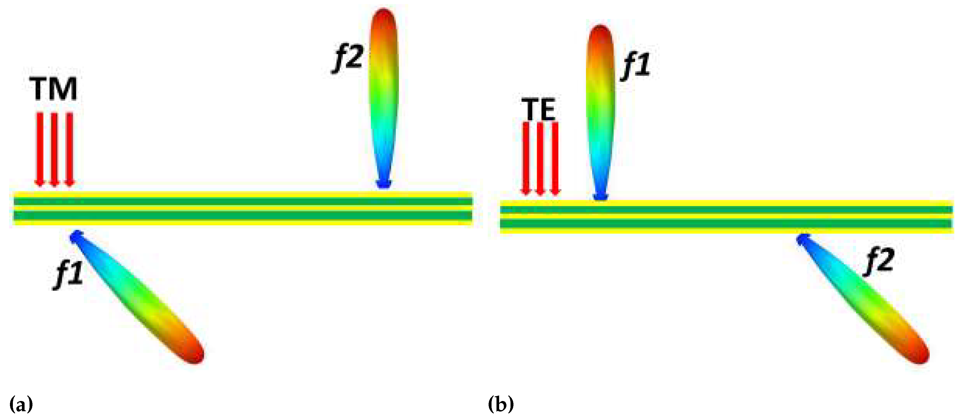
2. Working Principle
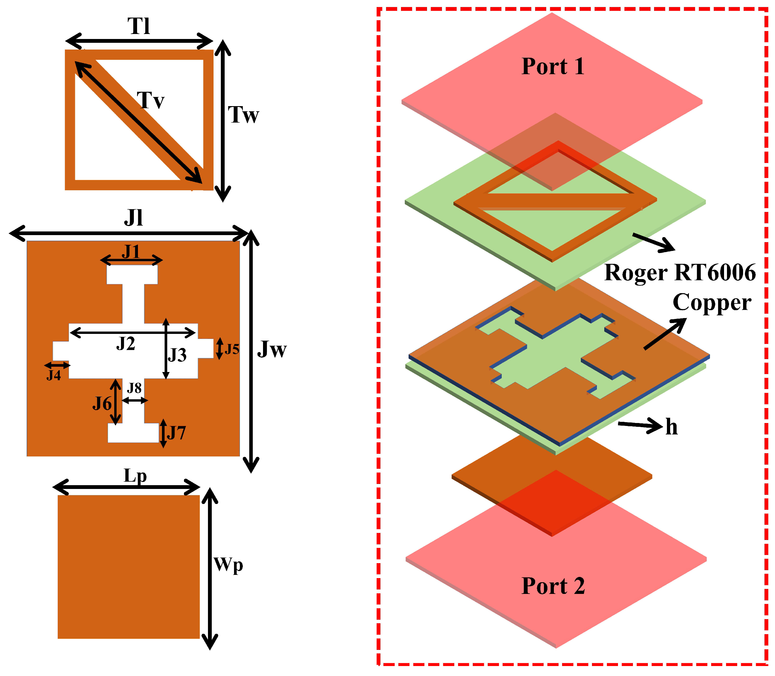
For elements with mirror symmetry, the electromagnetic properties can be expressed using two diagonal Jones matrices.
R ( x , y ) = r x x , f 1 ( x , y ) 0 0 r y y , f 2 ( x , y )
T ( x , y ) = t x x , f 2 ( x , y ) 0 0 t y y , f 1 ( x , y )
Here, the transmission and reflection coefficients and two principal axes x and y are represented by t x x , t y y , r x x , and r y y , respectively. In an ideal lossless system, | r x x | + | t x x | = 1 and | r y y | + | t y y | = 1 because of the energy conservation for efficient transmission | t x x | = | t y y | = 1; meanwhile, the reflection is considered zero. Similarly, for complete reflection | r x x | = | r y y | = 1, and the transmission will be zero. Transmitted and reflected waves must be manipulated together to have switchable phenomena in the dual bands. For this, Jones matrices must satisfy the following conditions [30].
| t x x , f 1 | = | r y y , f 1 | & | t y y , f 2 | = | r x x , f 2 |
The equation demonstrates that the metasurface exhibits an intriguing duality in its response to incident electromagnetic waves. Specifically, at the f1 frequency band, the metasurface manifests itself as a transparent medium for waves polarized in the x-direction, while adeptly functioning as a reflector for waves polarized in the y-direction. Subsequently, within the f2 frequency band, the metasurface assumes a contrasting behavior, reflecting x-polarized waves comprehensively, and transparently accommodating y-polarized waves. Both operational bands must have the capacity for agile tuning, according to the structure. Remarkably, by aligning the tuning of these frequency bands to achieve a state of harmonious overlap, characterized by efficient transmission and reflection attributes, the metasurface can seamlessly transition between the distinctive operational behaviors of these bands. A visual depiction of this innovative concept is presented in Figure 1, providing a schematic illustration of the proposed methodology. TRA metasurface for transmission and reflection depends on the polarization of the incidence waves.

3. Unit Cell Design

Figure 2 presents the structure of a multi-layer unit cell. Roger RT 6006 is used as a substrate. The strategic deployment of the middle and top layers is aimed at achieving the utmost efficiency in both transmission and reflection. The outcomes substantiate that the metasurface allows for the conversion of the transmission frequency range into a fully encompassing reflection frequency range, and vice versa. Table 1 lists the dimensions associated with a single unit cell.
Figure 3 displays the S-parameter characteristics of a unit cell for both the TM and TE modes. The analysis reveals that in the TM mode, the unit cell functions as a transmission mode element at lower frequencies, specifically around 6.3 GHz, whereas it operates as a reflective mode element at higher frequencies, such as 9.3 GHz. Conversely, in the TE mode, the unit cell behaves as a reflective element at a lower frequency, approximately 6.3 GHz, and shifts to a transmission band role at a higher frequency, around 9.3 GHz.
Figure 4 depicts the phase responses for reflection and transmission in both the TM and TE modes. These phase responses are observed for both lower- and higher-frequency bands.
The reflection phase of the proposed TRA metasurface can be controlled by varying the width (Wp) of the patch.
The influence of the “Wp” variation in the reflection phase response is demonstrated in Figure 5. Examination of Figure 5a reveals that within the realm of the transverse electric (TE) mode, altering “Wp” across 2 to 5 mm elicits a fluctuation in the reflection phase from 100 to −100 . Conversely, for the transverse magnetic (TM) mode, the reflection phase experiences a transformation spanning from 160 to −140 , as illustrated in the same figure. This intricate relationship between “Wp” adjustments and the resultant shift in the reflection phase underscores the dynamic control and adaptability achievable in the proposed system, affording tailored electromagnetic responses in tune with specific operational requirements. Likewise, the impact of “Wp” on transmission phase characteristics is elucidated in Figure 6. The discernible trend showcases that, through the manipulation of “Wp” within the interval of 3 to 4.5 mm, a consistent transmission phase of approximately 100 manifests itself in both TE and TM modes. This result underscores the controllable and robust nature of the proposed system, wherein adjustments to “Wp” engender uniform transmission phase behaviors across different polarization states, ensuring coherent and desirable electromagnetic propagation outcomes.

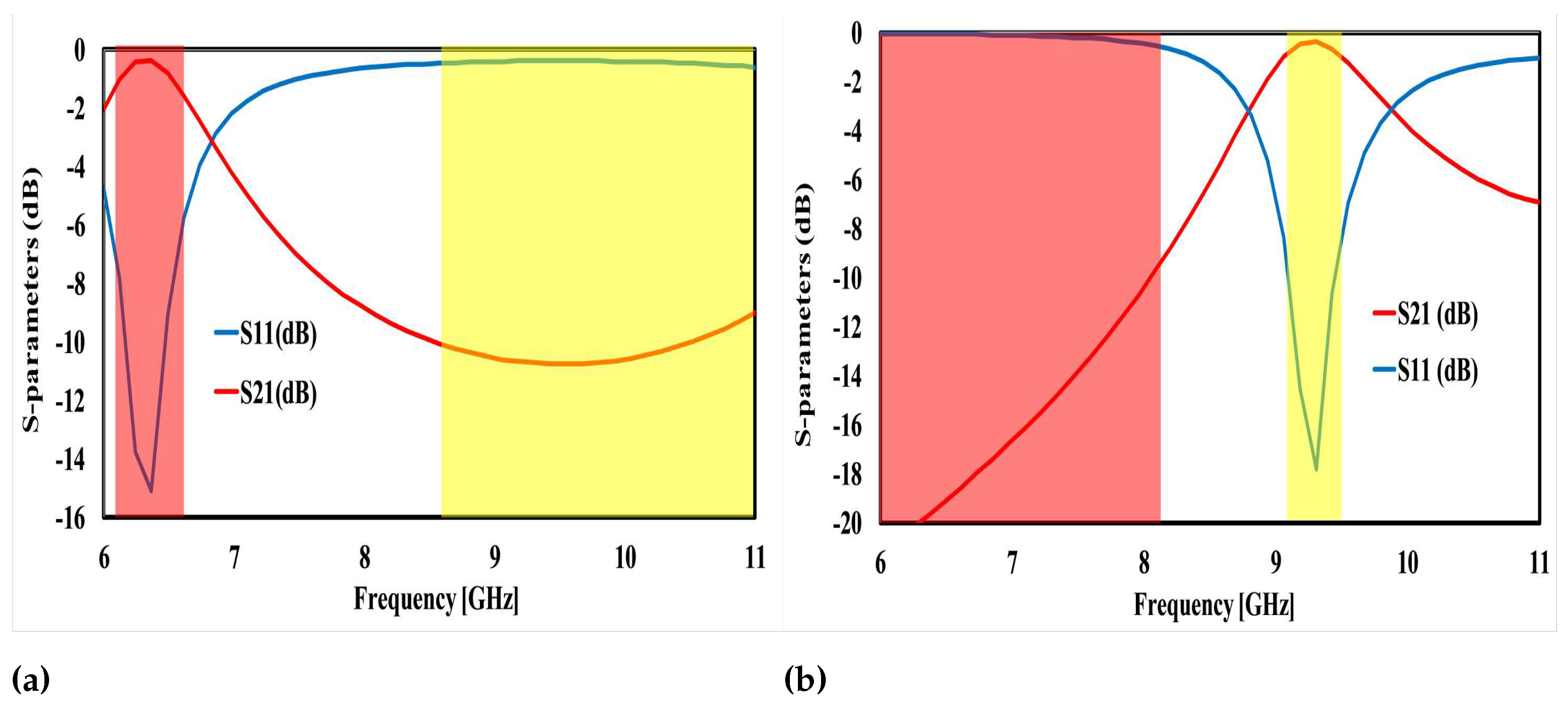
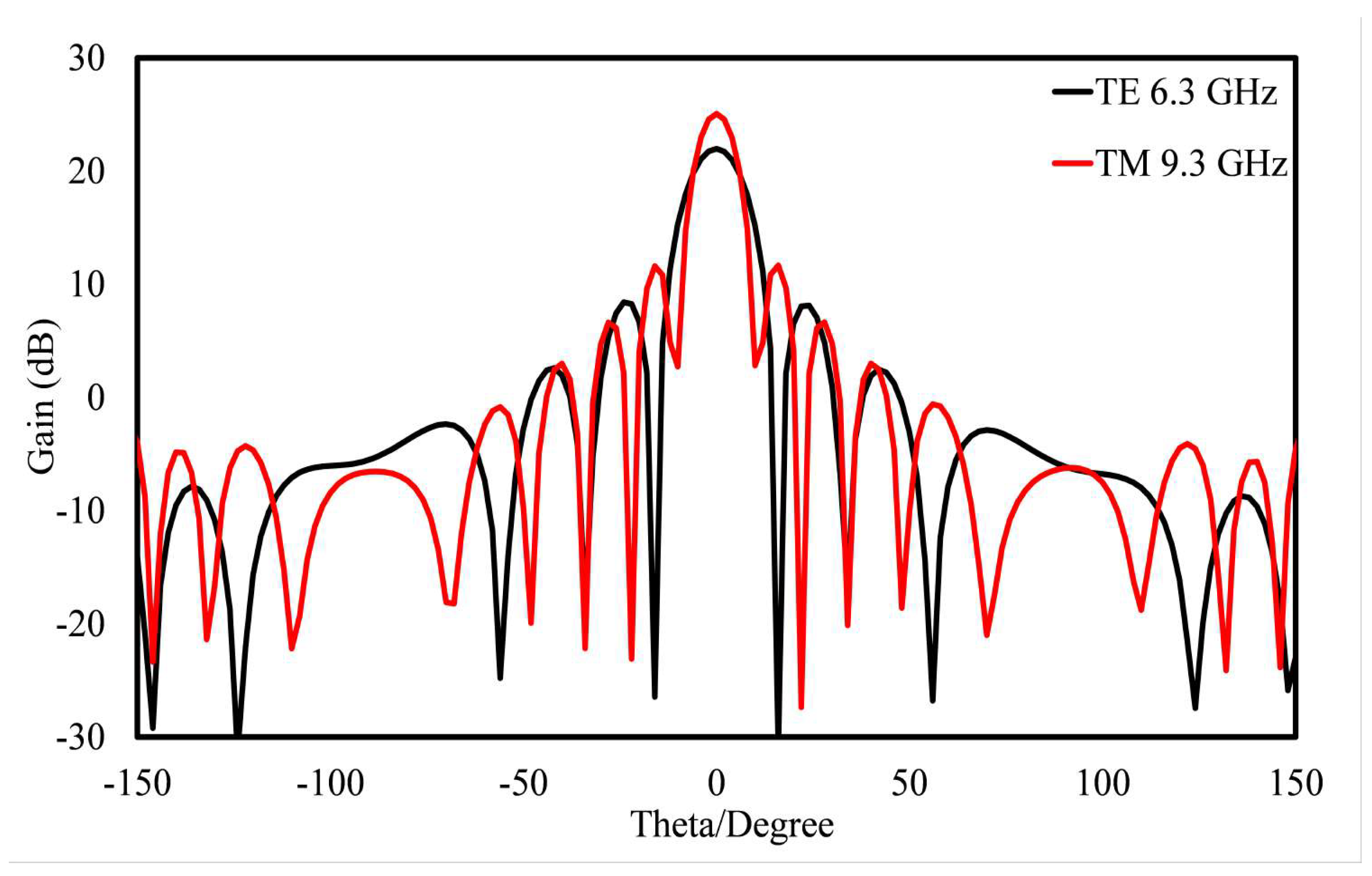
4. Design and Analysis of TRA Metasurface

In this section, a unit cell and its 23 × 23 elements array having a total area of 172.5 × 172.5 mm2 are designed and analyzed.

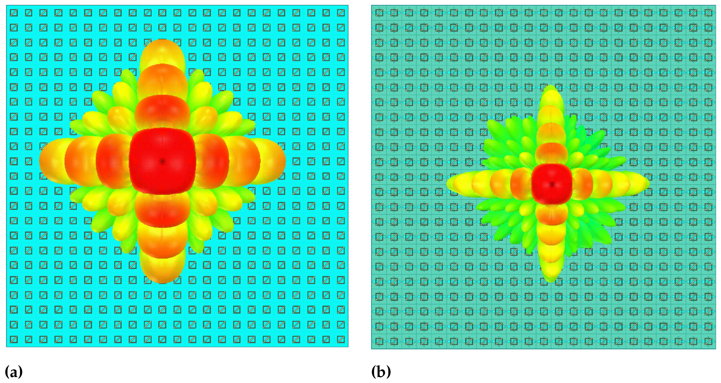
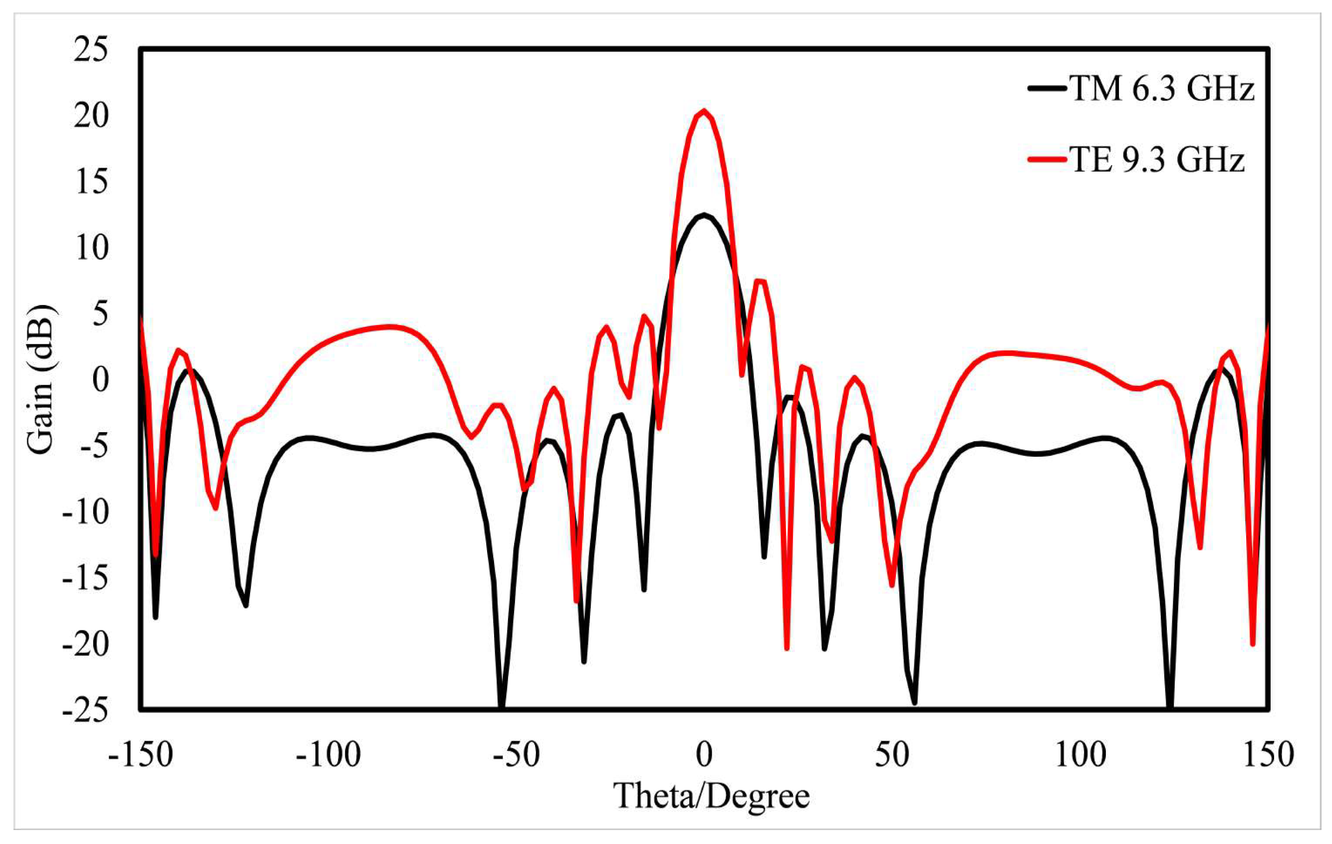
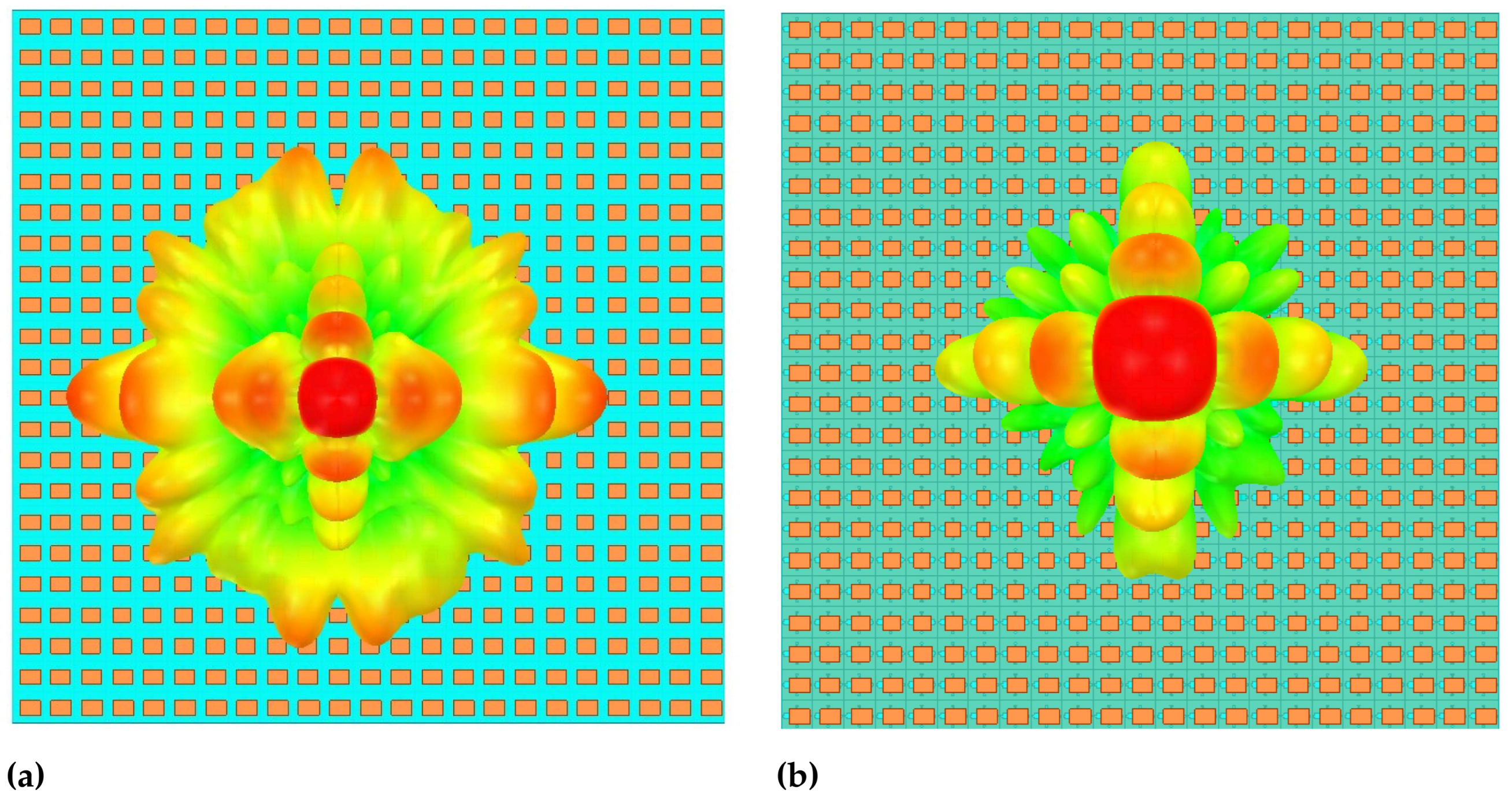
4.1. Reflect Array Functionality

Utilizing the distinctive attributes of the envisioned unit cell, a specialized array consisting of 23 × 23 elements has been meticulously developed. This array operates as a reflective unit for distinct frequencies, contingent upon the incident wave’s polarization. Specifically, in the case of TM mode, the array functions as a reflective entity at a frequency of 9.3 GHz. Conversely, when subjected to TE polarized waves, the same array operates as a reflective unit at 6.3 GHz. This versatile design showcases the capacity of the proposed unit cell to adapt to varying polarization conditions and frequencies, thus enhancing its applicability in multifaceted electromagnetic applications. Figure 7 presents the 2D reflection plot, providing a visual representation of the array’s performance. The reflective behavior of the array for distinct modes is evident from the figure. In TE mode, the array operates as a reflective structure at 6.3 GHz, whereas for the TM mode, it functions as a reflect array at 9.3 GHz. Notably, for both TE and TM modes, the reflective array exhibits a gain exceeding 20 dB, signifying its pronounced amplification capability. Moreover, the array showcases minimized side lobe levels, further emphasizing its capacity to ensure enhanced directivity and improved electromagnetic propagation characteristics.
Figure 8 showcases the 3D pattern of the proposed array, offering insights into its radiation characteristics. As depicted in Figure 8a, the array effectively operates as a reflector for the TE mode at 6.3 GHz. Similarly, the array serves as a reflect array for the TM mode at 9.3 GHz, indicating its versatile performance across different polarization states. This depiction highlights the array’s capacity to manipulate and control electromagnetic waves, resulting in tailored and efficient radiation patterns that align with specific frequency and polarization requirements.

4.2. Transmit Array Functionality

The functionality of the transmit array metasurface is presented in this section depending on the incident wave’s polarization. Specifically, in the TM mode, the array functions as a transmitter at 6.3 GHz, whereas for TE polarized waves, it acts as a transmitter at 9.3 GHz.
Figure 9 depicts a 2D transmission plot, providing insight into the array’s transmission characteristics. Evidently, the array operates as a transmitter for the TM mode at 6.3 GHz, and correspondingly, for the TE mode, it functions as a transmit array at 9.3 GHz. In the TE mode, the array achieves a gain exceeding 20 dB, whereas for the TM mode, the gain reaches 12 dB. This variation in gain can be attributed to losses and significant coupling between distinct components of the multilayer unit cell.
Figure 10 illustrates the 3D pattern for the transmit array scenario, offering a visual representation of its radiation characteristics. As depicted in Figure 10a, the proposed array functions as a transmit array for the TE mode at 9.3 GHz. Conversely, for the TM mode, it operates as a transmit array at 6.3 GHz.

5. Conclusions

In this manuscript, a strategy for a novel Transmit and Reflect Array (TRA) metasurface employing a multi-layered approach is proposed. Comprising three metallic layers interspersed with a Roger RT 6006 substrate, this metasurface serves as a versatile tool for transmitting and reflecting electromagnetic waves. Demonstrating its adaptability to distinct frequencies, specifically 6.3 GHz and 9.3 GHz, the metasurface dynamically responds to the polarization of incident waves. In the x-polarized (TM) mode, it acts as a transmit array at the lower frequency and transforms into a reflect array at the higher frequency. Alternatively, in the y-polarized (TE) mode, its function inversely transitions from a reflect array at 6.3 GHz to a transmit array at 9.3 GHz. Noteworthy attributes include its commendable gain performance and impressively low side lobe levels, collectively underlining its efficacy across wide electromagnetic applications.

Author Contributions

Conceptualization, A.A. and D.-Y.C.; methodology, A.A. and J.A.; software, A.A.; validation, A.A., J.A. and D.-Y.C.; formal analysis, A.A.; investigation, A.A. and D.-Y.C.; resources, D.-Y.C.; data curation, A.A., J.A. and D.-Y.C.; writing—original draft preparation, A.A.; writing—review and editing, J.A. and D.-Y.C.; visualization, D.-Y.C.; supervision, D.-Y.C.; funding acquisition, D.-Y.C. All authors reviewed the manuscript. All authors have read and agreed to the published version of the manuscript.

Funding

This research was supported by the Basic Science Research Program through the National Research Foundation of Korea (NRF) funded by the Ministry of Education (2022R1I1A3064544).

Data Availability Statement

Not applicable.

Conflicts of Interest

The authors declare no conflict of interest.

References

  1. Zhang, Z.; Yang, Q.; Gong, M.; Long, Z. Toroidal dipolar bound state in the continuum and antiferromagnetic in asymmetric metasurface. J. Phys. Appl. Phys. 2019, 53, 075106. [Google Scholar] [CrossRef]
  2. Zhu, B.O.; Feng, Y. Passive metasurface for reflectionless and arbitary control of electromagnetic wave transmission. IEEE Trans. Antennas Propag. 2015, 63, 5500–5511. [Google Scholar] [CrossRef]
  3. Huang, X.; Xiao, S.; Zhou, L.; Chan, C.; Shong, P. Photonic Metamaterials Based on Fractal Geometry. In Metamaterials: Theory, Design, and Applications; Springer: Berlin/Heidelberg, Germany, 2009. [Google Scholar]
  4. Veselago, V.G. Electrodynamics of materials with negative index of refraction. In Electromagnetic Materials; World Scientific: Singapore, 2003; pp. 115–122. [Google Scholar]
  5. Shelby, R.A.; Smith, D.R.; Schultz, S. Experimental verification of a negative index of refraction. Science 2001, 292, 77–79. [Google Scholar] [CrossRef]
  6. Pendry, J.B. Negative refraction makes a perfect lens. Phys. Rev. Lett. 2000, 85, 3966. [Google Scholar] [CrossRef]
  7. Dasgupta, A.; Gao, J.; Yang, X. Atomically thin nonlinear transition metal dichalcogenide holograms. Nano Lett. 2019, 19, 6511–6516. [Google Scholar] [CrossRef] [PubMed]
  8. Pors, A.; Nielsen, M.G.; Bernardin, T.; Weeber, J.C.; Bozhevolnyi, S.I. Efficient unidirectional polarization-controlled excitation of surface plasmon polaritons. Light. Sci. Appl. 2014, 3, e197. [Google Scholar] [CrossRef]
  9. Duan, J.; Guo, H.; Dong, S.; Cai, T.; Luo, W.; Liang, Z.; He, Q.; Zhou, L.; Sun, S. High-efficiency chirality-modulated spoof surface plasmon meta-coupler. Sci. Rep. 2017, 7, 1354. [Google Scholar] [CrossRef] [PubMed]
  10. Khorasaninejad, M.; Chen, W.T.; Devlin, R.C.; Oh, J.; Zhu, A.Y.; Capasso, F. Metalenses at visible wavelengths: Diffraction-limited focusing and subwavelength resolution imaging. Science 2016, 352, 1190–1194. [Google Scholar] [CrossRef] [PubMed]
  11. Sun, S.; Yang, K.Y.; Wang, C.M.; Juan, T.K.; Chen, W.T.; Liao, C.Y.; He, Q.; Xiao, S.; Kung, W.T.; Guo, G.Y.; et al. High-efficiency broadband anomalous reflection by gradient meta-surfaces. Nano Lett. 2012, 12, 6223–6229. [Google Scholar] [CrossRef]
  12. Yu, S.; Li, L.; Shi, G.; Zhu, C.; Shi, Y. Generating multiple orbital angular momentum vortex beams using a metasurface in radio frequency domain. Appl. Phys. Lett. 2016, 108, 241901. [Google Scholar] [CrossRef]
  13. Chen, W.; Balanis, C.A.; Birtcher, C.R. Checkerboard EBG surfaces for wideband radar cross section reduction. IEEE Trans. Antennas Propag. 2015, 63, 2636–2645. [Google Scholar] [CrossRef]
  14. Liu, S.; Cui, T.J.; Xu, Q.; Bao, D.; Du, L.; Wan, X.; Tang, W.X.; Ouyang, C.; Zhou, X.Y.; Yuan, H.; et al. Anisotropic coding metamaterials and their powerful manipulation of differently polarized terahertz waves. Light. Sci. Appl. 2016, 5, e16076. [Google Scholar] [CrossRef] [PubMed]
  15. Abdelrahman, A.H.; Elsherbeni, A.Z.; Yang, F. High-gain and broadband transmitarray antenna using triple-layer spiral dipole elements. IEEE Antennas Wirel. Propag. Lett. 2014, 13, 1288–1291. [Google Scholar] [CrossRef]
  16. Islam, N.A.; Choi, S. Compact folded dipole metasurface for high anomalous reflection angles with low harmonic levels. Sci. Rep. 2020, 10, 18125. [Google Scholar] [CrossRef] [PubMed]
  17. Charola, S.; Patel, S.K.; Parmar, J.; Jadeja, R. Multiband Jerusalem cross-shaped angle insensitive metasurface absorber for X-band application. J. Electromagn. Waves Appl. 2022, 36, 180–192. [Google Scholar] [CrossRef]
  18. Liao, J.; Guo, S.; Yuan, L.; Ji, C.; Huang, C.; Luo, X. Independent Manipulation of Reflection Amplitude and Phase by a Single-Layer Reconfigurable Metasurface. Adv. Opt. Mater. 2022, 10, 2101551. [Google Scholar] [CrossRef]
  19. He, K.; Ning, T.; Li, J.; Pei, L.; Zheng, J.; Wang, J.; Bai, B. Wavefront reconfigurable metasurface through graphene micro-ribbons with resonant strategy. Results Phys. 2023, 49, 106484. [Google Scholar] [CrossRef]
  20. Wang, L.; Shi, H.; Chen, X.; Qu, B.; Yi, J.; Zhang, A.; Xu, Z.; Liu, H. Multibeam Metasurface Antenna Enabled by Orbital Angular Momentum Demultiplexing Feeding for IoT Communication. IEEE Internet Things J. 2023, 10, 16169–16182. [Google Scholar] [CrossRef]
  21. Chesnitskiy, A.; Kosmynin, A.; Kosmynina, K.; Lemberg, K. Design of a multibeam metasurface antenna for LEO satellite communications payload. Eng. Res. Express 2022, 4, 045025. [Google Scholar] [CrossRef]
  22. Naveed, M.A.; Kim, J.; Javed, I.; Ansari, M.A.; Seong, J.; Massoud, Y.; Badloe, T.; Kim, I.; Riaz, K.; Zubair, M.; et al. Novel spin-decoupling strategy in liquid crystal-integrated metasurfaces for interactive metadisplays. Adv. Opt. Mater. 2022, 10, 2200196. [Google Scholar] [CrossRef]
  23. Kim, J.; Lee, Y.; Kang, B.; Woo, J.; Choi, E.; Kim, E.; Gwon, M.; Kim, D.; Wu, J. Fabrication of polarization-dependent reflective metamaterial by focused ion beam milling. Nanotechnology 2012, 24, 015306. [Google Scholar] [CrossRef] [PubMed]
  24. Naveed, M.A.; Ansari, M.A.; Kim, I.; Badloe, T.; Kim, J.; Oh, D.K.; Riaz, K.; Tauqeer, T.; Younis, U.; Saleem, M.; et al. Optical spin-symmetry breaking for high-efficiency directional helicity-multiplexed metaholograms. Microsyst. Nanoeng. 2021, 7, 5. [Google Scholar] [CrossRef] [PubMed]
  25. Khidre, A.; Lee, K.F.; Elsherbeni, A.Z.; Yang, F. Wide band dual-beam U-slot microstrip antenna. IEEE Trans. Antennas Propag. 2013, 61, 1415–1418. [Google Scholar] [CrossRef]
  26. Zhao, Y.; Zhang, Z.; Wei, K.; Feng, Z. A dual circularly polarized waveguide antenna with bidirectional radiations of the same sense. IEEE Trans. Antennas Propag. 2014, 62, 480–484. [Google Scholar] [CrossRef]
  27. Wu, J.; Lian, R.; Wang, Z.; Yin, Y. Strip-coupling circularly polarized antenna and its same-sense bidirectional array. J. Electromagn. Waves Appl. 2015, 29, 1859–1866. [Google Scholar] [CrossRef]
  28. Lu, L.; Jiao, Y.C.; Weng, Z.B.; Ni, T.; Zhang, C. Bidirectional circularly-polarised loop linear array fed by slotted SIW. Electron. Lett. 2016, 52, 1193–1194. [Google Scholar] [CrossRef]
  29. Hou, Y.; Li, Y.; Chang, L.; Zhang, Z.; Feng, Z. Bidirectional same-sense circularly polarized antenna using slot-coupled back-to-back patches. Microw. Opt. Technol. Lett. 2017, 59, 645–648. [Google Scholar] [CrossRef]
  30. Khan, H.A.; Huang, C.; Xiao, Q.; Abbas, S.M. Polarization-dependent coding metasurface with switchable transmission and RCS reduction bands. Micromachines 2022, 14, 78. [Google Scholar] [CrossRef]
Figure 1. Conceptual illustration for the proposed TRA metasurface (a) TM waves and (b) TE waves.
Applsci 13 10389 g001
Figure 2. Structure of a unit cell with three metal layers and its perspective view.
Applsci 13 10389 g002
Figure 3. S-parameters: (a) TM mode and (b) TE mode.
Applsci 13 10389 g003
Figure 4. Reflection and transmission phase of the unit cell: (a) TM mode and (b) TE mode.
Applsci 13 10389 g004
Figure 5. Reflection phase of the unit cell by varying the size (Wp) of the patch: (a) TE mode and (b) TM mode.
Applsci 13 10389 g005
Figure 6. Transmission phase of the unit cell by varying the size (Wp) of the patch: (a) TM mode and (b) TE mode.
Applsci 13 10389 g006
Figure 7. A 2D reflection.
Applsci 13 10389 g007
Figure 8. Reflection: (a) TE mode 6.3 GHz and (b) TM mode 9.3 GHz.
Applsci 13 10389 g008
Figure 9. A 2D transmission.
Applsci 13 10389 g009
Figure 10. Transmission: (a) TE mode 9.3 GHz and (b) TM mode 6.3 GHz.
Applsci 13 10389 g010
Table 1. Attributes of the proposed unit cell.
ParameterSize (mm)ParameterSize (mm)ParameterSize (mm)
Jw7.5Wp4.2J40.4
Jl7.5Lp3.8J50.5
Tw & Tl3.2J10.6J61.6
Tv3.8J26J70.3
h0.8J31.4J80.3
Disclaimer/Publisher’s Note: The statements, opinions and data contained in all publications are solely those of the individual author(s) and contributor(s) and not of MDPI and/or the editor(s). MDPI and/or the editor(s) disclaim responsibility for any injury to people or property resulting from any ideas, methods, instructions or products referred to in the content.

