Article

Development of Active Microvibration Isolation System for Precision Space Payload

1
Key Laboratory of Space Active Opto-Electronics Technology, Shanghai Institute of Technical Physics, Chinese Academy of Sciences, Shanghai 200083, China
2
University of Chinese Academy of Sciences, Beijing 100049, China
*
Authors to whom correspondence should be addressed.
Appl. Sci. 2022, 12(9), 4548; https://doi.org/10.3390/app12094548
Submission received: 24 March 2022 / Revised: 27 April 2022 / Accepted: 27 April 2022 / Published: 30 April 2022
(This article belongs to the Special Issue Sensors, Actuators and Methods in Active Noise and Vibration Control)

Abstract

:
In this study, an active microvibration isolation system is developed for precision space payload. Vibrational environment affects the performance and reliability of measuring instruments. To improve the measurement accuracy of the precision space payload, an active vibration isolation system based on eight vibration isolation modules, which are applied for microvibration isolation on the satellite, is designed. A vibration suppression control strategy for multiple degrees of freedom is studied. A hybrid control method involving a feedback and a feedforward controller based on a nonlinear tracking differentiator and an nth-order weak integrator, respectively, was adopted to optimize the suppression effect of microvibration. As a result, the microvibration of the order of mg can be reduced to the order of μg through the active control of modules. Research experiment results show that the root cumulative power spectral density of the systemic sensitive frequency band in the range of 0.5–200 Hz, i.e., microvibration frequency band in the optical reference cavity, has been reduced to in the order of μg in three directions, which satisfied the requirements of aerospace engineering.

1. Introduction

In the field of metrology with high precision and sensitivity, precise and repeatable results indicate high specification vibration environmental requirements [1]. The optical clock, being the most accurate time-frequency measurement system, can obtain high-precision frequency and time signals, which is of great significance in scientific experiments such as basic physical constant measurement [2,3], synchronous quantum communication [4,5], and gravitational wave detection [6,7]. In 2014, the frequency uncertainty of the Sr atomic optical clock built by the JILA laboratory in the United States reached 10−18 [8]. To achieve a higher theoretical limit, various research teams have focused on the construction of space optical clocks because the interference from gravity disturbance in space is lower than that on Earth. The two projects proposed by ESA, namely the atomic clock ensemble in space program (ACES) [9], and the Space Optical Clocks Project (SOC) [10] are space-oriented optical clock tests, whose uncertainty targets are above 10−16. However, the microvibration on the satellite caused by the interference of the flywheel, solar sail, and attitude adjustment mechanism [11,12,13] has become a considerable issue that prevents the optical clock from improving the instability. For example, in Feng Yun-4 meteorological satellite, when the cryocooler is working, the vibration of the satellite top plate is approximately 1 mg within 200 Hz [14]. Such micro-vibrations will change the length of the optical reference cavity, which will lead to the deterioration of the frequency uncertainty of the optical clock and affect the final measurement accuracy. To suppress the interference caused by microvibration, (1) the optical reference cavity should be designed to minimize the sensitivity to vibration [15,16], and (2) the transmission efficiency of microvibration should be suppressed as much as possible in the transmission path of microvibration [17,18]. For the optical clock at an uncertainty level of 1 × 10⁻¹⁸ frequency, the frequency instability of the optical reference cavity of 3 × 10⁻¹⁶ is required. Moreover, the vibrational environment of the cavity cannot be higher than 1.5 × 10⁻⁵ g because the vibration sensitivity of the optical cavity will be under 2 × 10⁻¹¹/g [19] as per the existing conventional reference cavity design.
The traditional passive vibration isolation system is widely used because of its high reliability and excellent high-frequency vibration isolation performance. However, in the lower frequency range, the passive vibration isolation system needs to reduce the resonant frequency as much as possible to obtain better vibration isolation performance [20,21]. Nevertheless, the stability of this design makes it difficult to support such a precise system as an optical clock. Therefore, to fulfill the demand for high-precision vibration isolation in space, the active vibration isolation technology is the main method used.
The active vibration isolation system developed at Eindhoven University of Technology adopts the design of multiple SISO control loops as a basis and uses a method with acceleration and position feedback to achieve a maximum suppression efficiency of 97% within 100 Hz, and optimizing the leveling performance [22]. The active vibration isolation system junction developed by Huazhong University of Science and Technology uses a centralized control method to suppress vibrations of 200 Hz by 94.8% through a sensor and actuator matrix and a controller design based on absolute velocity feedback [23]. The active vibration isolation systems of these ground tests have proven to exhibit excellent performance, but their volume and weight are relatively large, which are limited by space platform resources. For space high-precision payloads, the application of active vibration isolation technology is also gradually developing. The MVIS-II developed by the Kirtland Air Force Laboratory of the United States has a 20 dB attenuation effect in the frequency band greater than 5 Hz, and a flight test was carried out in 2006 [24]. China’s Technology and Engineering Center for Space Utilization also developed a MAIS vibration isolation system with a combination of acceleration feedback and relative position feedback, and conducted flight experiments on the Tianzhou-1 cargo spacecraft in 2017, where vibrations in the range of 0.1–10 Hz were suppressed to 10−8 g [25,26]. Considering that the microvibration on a satellite is usually a complicated and broadband input, an active vibration isolation system is suitable for the frequency band range (0.5–200 Hz) and the suppression effect (root cumulative PSD is below 1.5 × 10⁻⁵ g) of the optical reference cavity in space still needs to be further studied.
In this paper, an active vibration isolation system applied to precision space payload is developed. A hybrid controller composed of feedforward and feedback is designed to achieve vibration suppression in three directions in a broadband micro-vibration noise environment through eight vibration isolation modules based on the method of decentralized control. The phase change caused by the controller and various filters is considered, and a lead-lag compensator is designed and added to ensure the stability of the system. The proposed active vibration isolation system and control algorithm are finally confirmed by experimental studies.
In this study, an active vibration isolation system for microvibration is introduced. The discussion is organized into four sections. (1) The composition of the system, including the overall configuration and control principle of a single vibration isolation module, is described. (2) The design of the hybrid control law and simulation results are described in detail. (3) An experiment and result analysis of the system were carried out. (4) The conclusion is summarized in final section.

2. System Composition

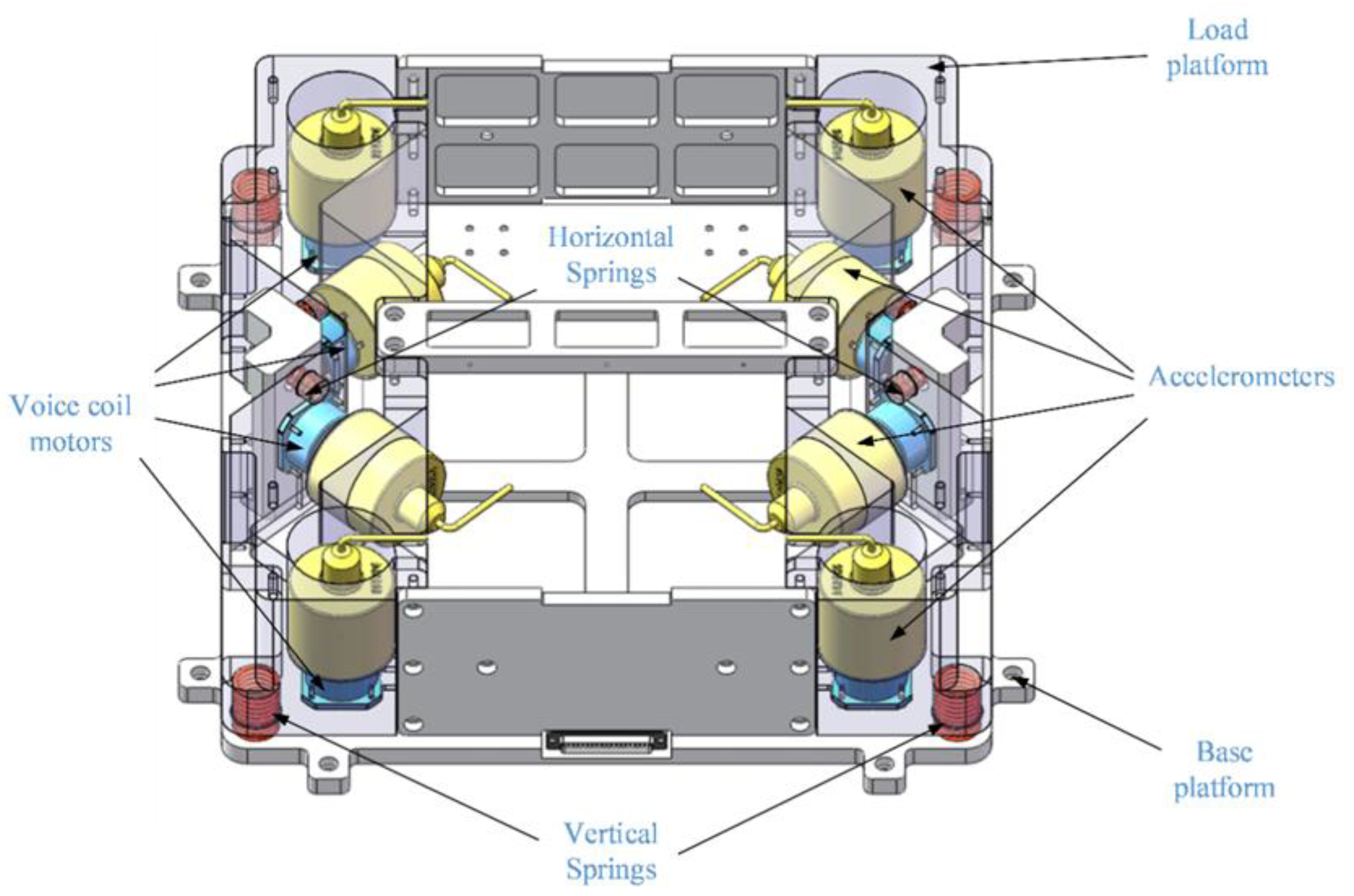
2.1. Configuration and Composition of Active Vibration Isolation Platform

A vibration isolation system for a space optical cavity with a voice coil motor was designed as an actuator. Figure 1 shows the structural layout of an active vibration isolation platform (AVIS). The entire system consists of a foundation platform, a load platform, and eight vibration isolation modules. Each module is composed of a coaxially mounted sensor and a voice coil motor to ensure that the measured signal and control force are coaxial and in the same direction. For vertical and horizontal stiffness, the load platform was connected to the base platform using springs. The eight vibration isolation modules are arranged orthogonally in the vertical and horizontal directions, and the layout direction is shown in Figure 1. The acceleration signal of the load platform is picked up by the sensor, and it is sent to the driver through the controller. The control force generated by driving the voice coil motor acts on the load platform. By using a decentralized control approach, each vibration isolation module features its sensor and actuator as the single-input single-output (SISO) [27]. In this way, the control force output by multiple SISO loops is used to achieve vibration suppression of the system in three directions.

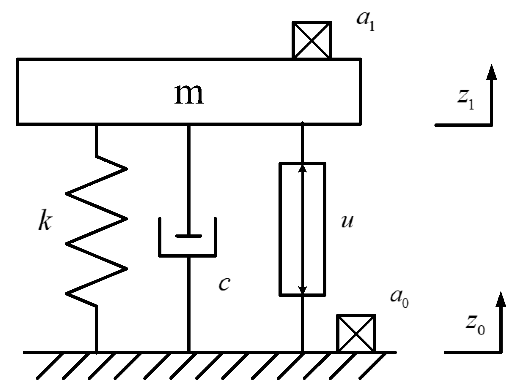
2.2. Principle of Vibration Isolation Module

A diagram of a single active vibration isolation module of the isolation platform is shown in Figure 2. The equivalent stiffness and damping of the system are represented as k and c , respectively, and the total mass of the loaded platform is m , which constitutes the passive structure. The active control force u provided by the voice coil motor can reduce the influence of the noise a 1 transmitted from the base plane noise a 0 , z 0 and z 1 correspond to the displacements of the base platform and the load platform, respectively. The dynamic equation can be expressed as
m z ¨ 1 + c z ˙ 1 + k z 1 = u + c z ˙ 0 + k z 0 ,
The diagram of the SISO control loop for a single vibration isolation module in the system is shown in Figure 3, which includes feedforward controller and feedback controller. The control block C 0 provides the feedforward control force u f f using the acceleration a 0 measured base platform, and the control block C 1 provides the feedback control force u f b using the acceleration a 1 of the load platform. The resultant force u acts on the AVIS to suppress the disturbance on the load platform by the voice coil motor.
The objective of the control is to design appropriate controllers C 0 and C 1 so as to suppress the noise disturbance on the load platform as much as possible in the required frequency band. According to the above control force design, the dynamic equation can be expressed as follows:
m z ¨ 1 + c z ˙ 1 + k z 1 = c z ˙ 0 + k z 0 + C 0 z ¨ 0 + C 1 z ¨ 1 ,
After Laplace transform, the function is given as:
( m s 2 + c s + k C 1 s 2 ) z 1 = ( c s + k + C 0 s 2 ) z 0 ,
Owing to the relationship between displacement and acceleration z 0 = a 0 s 2 , z 1 = a 1 s 2 , the transfer function can be expressed as
G ( s ) = a 1 a 0 = c s + k + C 0 s 2 m s 2 + c s + k C 1 s 2 ,
It can be seen from Equation (4) that vibration suppression can be achieved by designing controllers C 1 and C 0 .

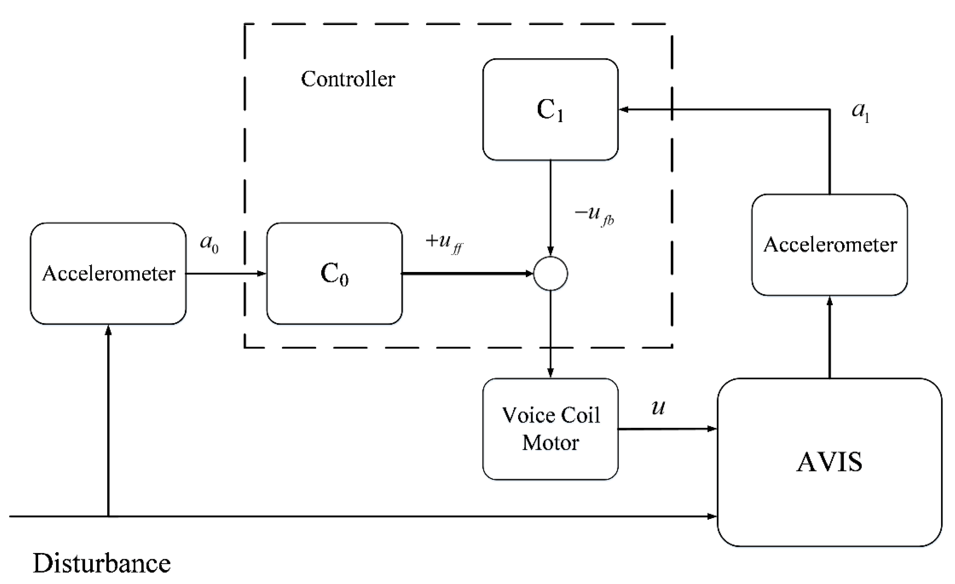
3. Hybrid Control Design

3.1. Feedback Control

For a single vibration isolation module, the feedback controller C 1 can be designed to be used as a PID controller.
C 1 = K P + K I s + K D s ,
where K P is the proportional term of acceleration; it can change the virtual mass of the system, improve the resonant frequency of the closed-loop control system, and optimize the suppression ability of the high-frequency band to interference, and K I is the integral term of acceleration, which can provide skyhook damping for the system to enhance the suppression ability of the active vibration isolation system at the resonant frequency. K D represents the differential term of the acceleration and its trend.
Because the feedback loop controls the voice coil motor by measuring the acceleration signal, the output signal needs to change continuously with the input signal to ensure that the vibration of the load platform approaches zero. To improve the tracking and control ability for time-varying acceleration input signals and avoid overshoot caused by excessive gain, a transition process based on a tracking differentiator is added to the feedback controller. Considering the faint acceleration amplitude of microvibration, to avoid the chattering introduced by the differentiator in the solution, a discrete nonlinear tracking differentiator is selected to obtain the tracking signal and its differential value. The expression is as follows:
{ r 1 ( k + 1 ) = r 1 ( k ) + h r 2 ( k ) r 2 ( k + 1 ) = r 2 ( k ) + h f s t ( r 1 ( k ) v ( k ) , r 2 ( k ) , δ , h ) ,
where h is the sampling period, v ( k ) is the input signal of the h t h sequence, δ is a parameter that determines the speed of tracking, r 1 ( k ) and r 2 ( k ) is the tracking signal and differential tracking signal of v ( k ) , respectively. f s t is the optimal control synthesis function of the discrete-time system, which is expressed as:
f s t ( x 1 , x 2 , δ , h ) = { δ s i g n ( a ) | a | > d δ a d | a | d ,
a = { x 2 + a 0 d 2 s i g n ( y ) | y | > d 0 x 2 + y h | y | d 0 ,
where d = δ h , d 0 = h d , y = x 1 + h x 2 , a 0 = d 2 + 8 δ | y | .
After the tracking differentiator, the control signal in the feedback loop with the recursive notation is given as
u C 1 ( i ) = u C 1 ( i 1 ) + K P [ r 1 ( i ) r 1 ( i 1 ) + T 0 T i r 1 ( i ) + T d ( r 2 ( i ) r 2 ( i 1 ) ) ] ,
where T 0 is the sampling period, T i and T d are the integration and derivative time constant.
Increasing the feedback gain can change the resonant characteristics of the system to improve the vibration suppression effect, however, the exorbitant gain will also cause problems such as signal drift and actuator saturation. Therefore, it is necessary to add a high-pass filter to the loop for filtering. The transfer function of the first-order high-pass filter is as follows:
H h i g h - p a s s ( s ) = s s + ω c ,
where ω c is the cut-off frequency.
Moreover, the input signal is passed through a low-pass filter to increase the control gain of a specific frequency band through frequency division control, thus focusing on suppressing the noise of the frequency band.
The introduction of high- and low-pass filters affects the phase of the system, which results in a decline in the stability of the system. This can be directly observed by calculating the Bode diagram of the open-loop system function. The Bode diagram in Figure 4 reveals that the exorbitant gain leads to an insufficient phase margin and easy oscillation in the open loop. To ensure the stability of the system and increase the phase margin, a lead-lag phase filter is added to the feedback control. The transfer function of the lead-lag phase compensation filter is as follows:
H l e a d - l e g ( s ) = K s Z c + 1 s P c + 1 = K i ω ω 1 + 1 i ω ω 2 + 1 ,
where K is the gain, Z c and P c are the zero and pole of this filter, respectively, ω 1 and ω 2 are the corresponding angular frequencies.
With the Tustin transformation as follows
s = 2 T 1 z 1 1 + z 1 ,
where s = i ω , T is the sampling time.
The filter transfer function can be transformed into discrete z-plane
H l e a d - l a g ( z ) = K ω 2 ω 1 T ω 1 + 2 + ( T ω 1 2 ) z 1 T ω 2 + 2 + ( T ω 2 2 ) z 1 ,
The lead phase filter, 0 < ω 1 < ω 2 , is used in this study. After the lead phase filter is added, the open-loop Bode diagram of the system is shown as the real line in the figure, the crossover frequency has been changed from 127 to 437 rad / s , and the phase margin was increased to 30°.
In addition to the lack of phase margin, the modal frequencies of the system and the resonant frequencies from the base platform can cause large vibrations when driving the motor. Moreover, the output of the controller is not completely ideal, and some noise signals not coming from disturbance sources are found in the output voltage. These noises can also bring vibration to the system at the corresponding frequencies and affect the stability of the active control. Therefore, it is necessary to design notch filters for these noises to further improve the vibration isolation performance. To reduce the calculation in the program, IIR (infinite impulse response) notch filter is selected, and the transfer function is as follows:
H n o t c h ( s ) = K s 2 + 2 γ 1 ω 0 s + ω 0 2 s 2 + 2 γ 2 ω 0 s + ω 0 2 ,
where K is the gain, ω 0 is the cut-off frequency, γ 1 and γ 2 are the parameters of depth and bandwidth and 0 < γ 1 < γ 2 .
The transfer function of notch filter is given using the Tustin transformation function as follows:
H n o t c h ( z ) = K ( 4 + 4 γ 1 ω 0 T + ω 0 2 T 2 ) + ( 2 ω 0 2 T 2 8 ) z 1 + ( 4 4 γ 1 ω 0 T + ω 0 2 T 2 ) z 2 ( 4 + 4 γ 2 ω 0 T + ω 0 2 T 2 ) + ( 2 ω 0 2 T 2 8 ) z 1 + ( 4 4 γ 2 ω 0 T + ω 0 2 T 2 ) z 2
The parameters for all the filters are listed in Table 1.

3.2. Feedforward Control

In the actual experiment, the noise frequency of the basic platform could not be classified as an ideal white noise, however, it comprises some type of a mixed noise of a specific frequency, which makes it difficult for the feedback loop to suppress these specific noises caused by the base platform when only measuring the acceleration signal of the load platform as the control input. Therefore, feedforward control is selected to optimize the vibration isolation effect by simultaneously measuring the input noise of the vibration source and integrating it into the control signal. The diagram of the hybrid control loop after adding the feedforward controller is as follows:
According to Equation (4), the influence of the feedforward gain coefficient C 0 on vibration transmission is mainly reflected in the numerator of the transfer function. To isolate the vibration with high efficiency, the transfer function of the vibration is expected to be 0, so that C 0 can be designed as:
C 0 ( s ) = d s + k s 2 ,
Multiple integration links are observed to be contained in this controller, and ideal integration is infeasible in practice because of the drift of the low-frequency acceleration signal after integration. For this problem, M. A. Beijen proposed utilizing the n-th order weak integrator, which integrates a certain frequency to substitute for the ideal ones [28]. The revised feedforward controller can be expressed as:
C 0 = H 2 ( ω , n ) ( s ) ( d s + k ) ,
where H ( ω , n ) ( s ) is an n-th order weak integrator, and ω is the cut-off frequency. In this study, n = 2 and ω = 0.2 rad / s , and the integrator can be written as
H ( ω , n ) ( s ) = 1 ( ω s + ω ) n s = 1 ( 0.2 × 2 × π s + 0.2 × 2 × π ) 2 s ,
Using the Tustin and describe transformation, the output signal of weak integrator is given as:
H n w i ( z ) = 2 T + 2 ω T 2 + ( 4 ω T 2 ) z 1 + ( 2 T + 2 ω T 2 ) z 2 ( ω T + 2 ) 2 + ( 2 ω 2 T 2 8 ) z 1 + ( ω T 2 ) 2 z 2
According to Equation (4) and Figure 5, the simulation curves of several different controllers are shown in Figure 6. Evidently, the feedback controller has a significant suppression effect, especially on the resonant peak. However, the effect within the low-frequency band before the resonance frequency proved to be insufficient. At this point, the hybrid controller was optimized with the addition of feedforward part.

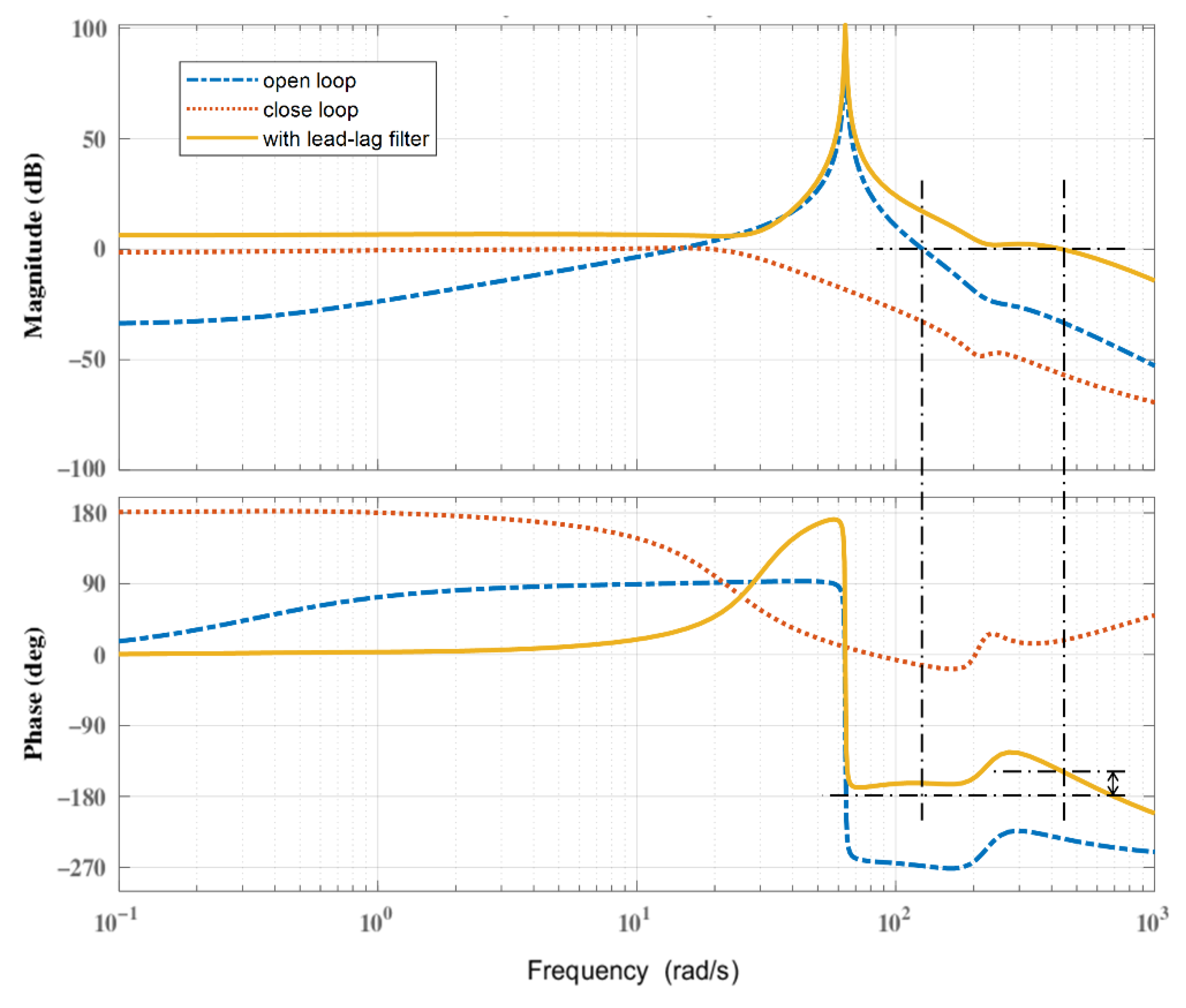
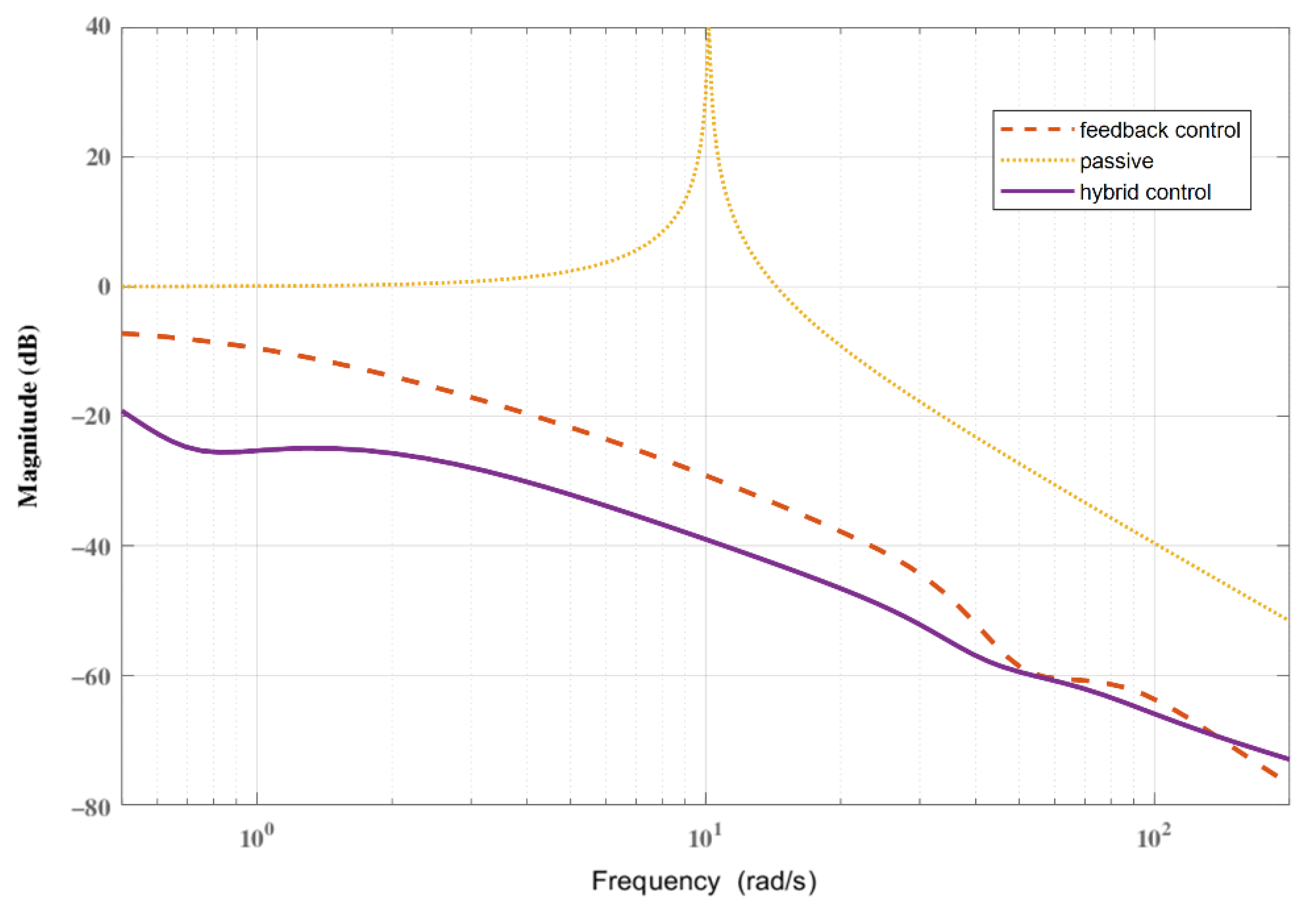
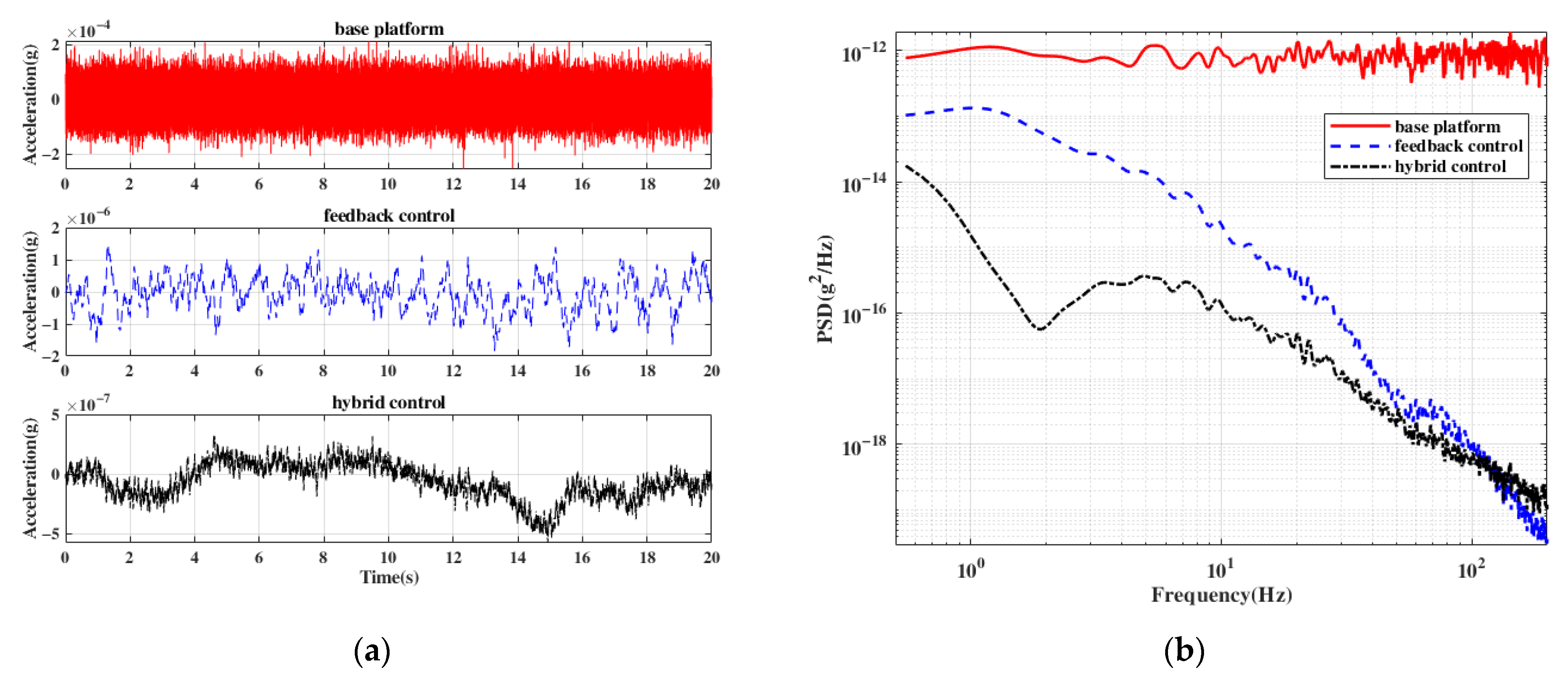
3.3. Simulation Experiment

Simulation experiments of a single vibration isolation module were conducted to compare the dynamic characteristics of the feedback and hybrid control. The dynamic model of the system refers to Equation (4) and the simulated physical parameters are close to the real system parameters. The vibration signal in the time domain and the power spectral density obtained from the experimental results are shown in Figure 7.
Figure 7a,b show the acceleration signal in the time domain and their power spectral density (PSD). A random vibration with a value of 0.2 mg is added to the base platform as an input disturbance. It can be seen that the feedback control has a considerable suppression effect in the entire frequency band, and the acceleration amplitude of the load platform is suppressed to 2 μg. With hybrid control, the acceleration amplitude is further suppressed to 0.6 μg. Below the frequency of 10 Hz, the residual disturbance of the load platform also obtains a more anticipated suppression performance. Therefore, the feedback control method can remove the residual acceleration, and the hybrid control method can further improve the active vibration isolation performance.

4. Experimental Validation

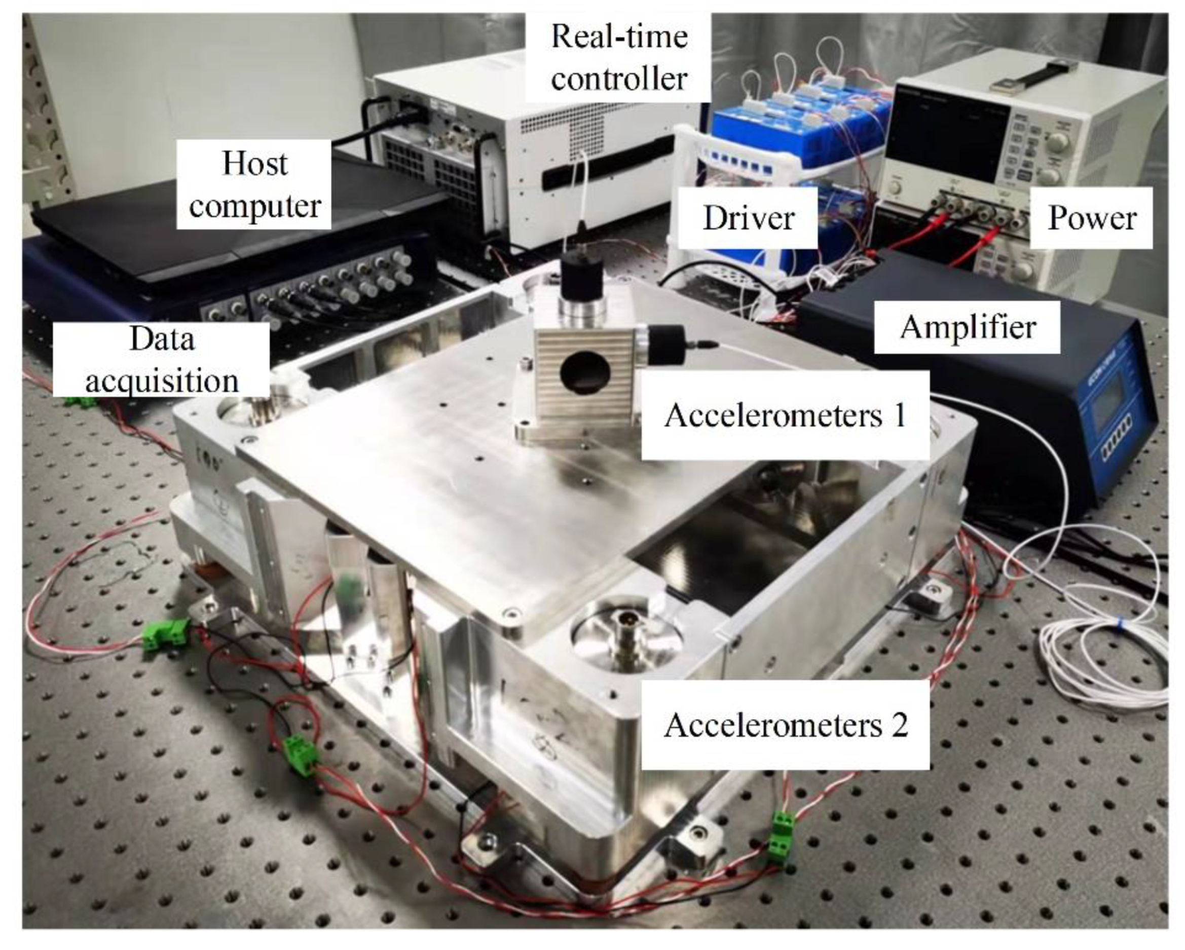
4.1. Set Up of Experimental System

To verify the effectiveness of the above mentioned vibration isolation control scheme, a prototype of the vibration isolation system was established, as shown in Figure 8. The structure of the system is shown in Figure 1. The acceleration signal of the load platform was measured using the acceleration sensors in the vibration isolation module. The signal is processed according to the designed active vibration isolation control algorithm using the real-time controller, then it is collected and output through AD/DA. Finally, to suppress the disturbance of the platform, the voice coil motor was driven by a linear power amplifier. Moreover, to observe variances, the monitoring signal of the load platform in three directions was measured by accelerometer 2. The host computer can obtain the signal in the real-time controller and modify the control parameters. The overall control of the system was realized using LabVIEW 2020 programming. The physical and controller parameters of the system are listed in Table 2 and Table 3.

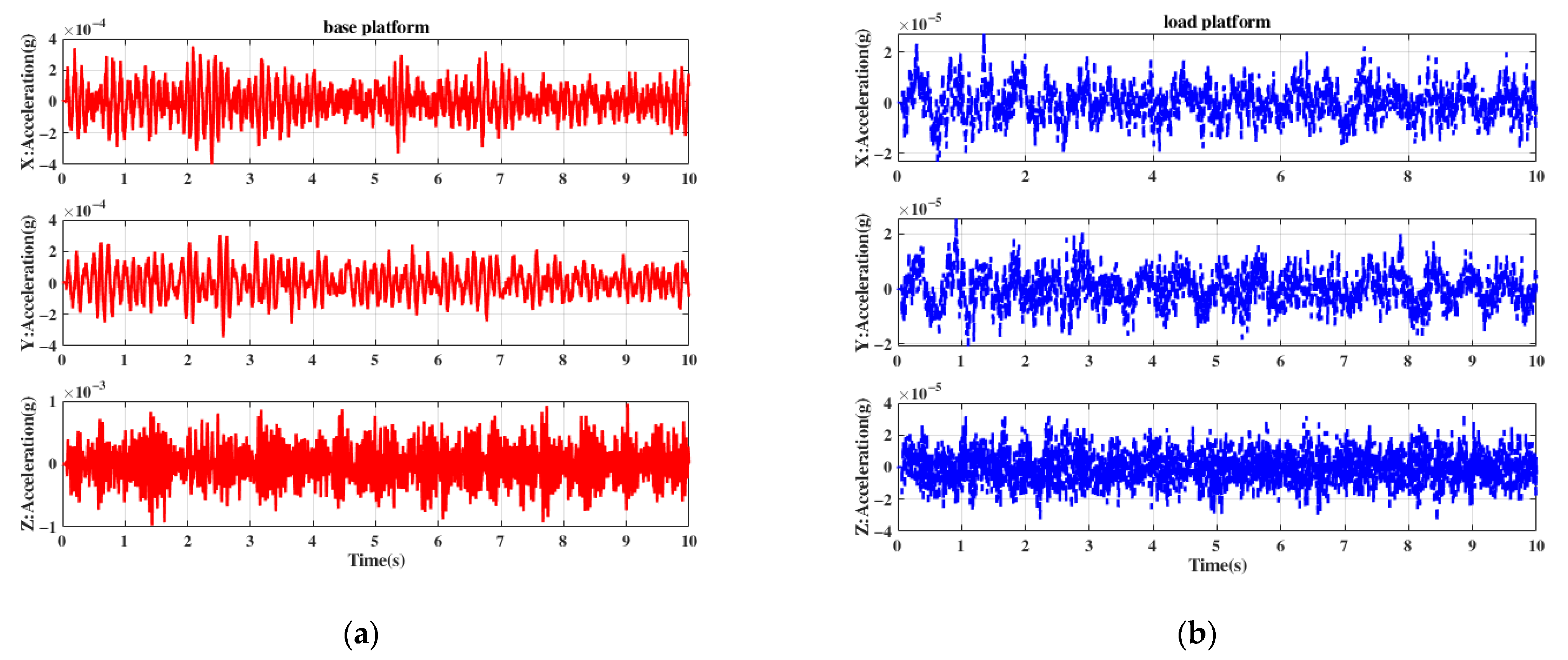
4.2. Analysis of Experimental Results

The experimental system was installed on an optical platform, and its environmental vibration was regarded as the input disturbance. The disturbance is transmitted to the load platform through springs, etc. Through the feedback control of eight vibration isolation modules, the vibration in three directions of the load platform is suppressed. Owing to the limitation of the channel numbers, only four vibration isolation modules can be used in the experiment of hybrid control to suppress the vibration in Z direction.
The time-domain signals of the base platform and load platform in the x-, y-, and z-axes are shown in Figure 9a,b. The disturbance in each axis of the base platform is less than 1 mg, which is closer to the vibration response of the roof of the FY-4 satellite. With the feedback control, for the x and y axes, the acceleration amplitude of the time domain was suppressed from 0.2~0.5 mg to 20 μg at most, and for the z axis, the acceleration amplitude was suppressed from 1 mg to 40 μg. Figure 9c,d present the PSD and root cumulative PSD plots within 200 Hz, which shows that the addition of feedback leads to improvements in performance in the frequency domain. For the x and y axes, the root cumulative PSD was reduced from 9.78 × 10⁻⁵ g and 9.22 × 10⁻⁵ g to 6.52 × 10⁻⁶ g and 6.17 × 10⁻⁶ g, respectively, with an attenuation rate of 93.3%. For the low-frequency band within 10 Hz, the attenuation rate of the vibration reached 94.2%. For z-axis, the root cumulative PSD was reduced from 2.89 × 10⁻⁴ g to 8.96 × 10⁻⁶ g, and the attenuation rates within 200 Hz and 10 Hz were 96.9% and 93.4%, respectively. The root integration of the PSD within 200 Hz of each axis reached the μg level.
To verify the effect of hybrid control, a comparative experiment of feedback control and hybrid control was carried out along the z axis. An extra acceleration sensor was installed on the base platform of the vibration isolation system to collect the acceleration signal as the input source of the feedforward loop. As shown in Figure 10, the low-frequency suppression effect of hybrid control within 10 Hz is more evident than that of feedback control, and further attenuation can be realized near 24 Hz, which is the resonant frequency of the optical platform. With hybrid control, the acceleration amplitude of the time domain was suppressed to 20 μg, the root cumulative PSD within 200 Hz was reduced to 7.2 × 10⁻⁶ g, which improved by 18.8% compared with the feedback control. The attenuation rates within 200 Hz and 10 Hz were 97.4% and 95.9%, respectively.

4.3. Discussion

Compared to some vibration isolation systems used for ground experiments [22] with mass 1300 kg and resonant frequency 1.8 Hz, the active vibration isolation system designed in this paper is smaller in size and mass (25 kg) and higher in resonant frequency (10 Hz) which is advantageous for the limited resources available on the satellite. Although this design with high resonant frequency is not conducive to passive vibration isolation, the performance of the system can still get similar results with active control. In addition, compared to some other systems with similar structure [29], the decentralized control strategy adopted in this paper, which could do without the structural information of the system and matrix operations, reduces the complexity of the control loop. The experimental results in this paper also prove that the used hybrid control strategy has a better suppression effect for low frequency signals, extending the effective starting frequency of vibration isolation from 5 Hz to 0.5 Hz. According to the requirement of the precision payload, the acceleration after isolation should be small in enough, so the judgement of the isolator designed in this paper is not only on the suppression ratio, but also on the absolute magnitude of acceleration, which is different from these isolation systems above.
However, it can be noticed that there are some prominent frequencies of acceleration on the load platform, such as 8 Hz in the X and Y directions and 24 Hz in the Z direction. These noises represent a significant component of vibration source which originated from the resonant frequencies of the optical stage. Under this circumstance, the performance of vibration isolation could be optimized by designing controllers with different gains for different frequency intervals. Besides, for further improving the performance of vibration isolation systems with the microvibration source, the noise from the system itself is not negligible, such as sensor noise, actuator noise and noise brought by cables [30]. The suppression of these disturbances were not considered in this paper which may limit the current performance of vibration isolation. Resolution of these issues will lead to better achievement in future research.

5. Conclusions

In this paper, an active vibration isolation platform for a precision space payload is proposed, designed, and tested. Eight modules based on voice coil motors were adopted to achieve isolation of multiple degrees of freedom. A hybrid controller, which is a combination of feedback with feedforward controllers, was designed and verified through simulations and experiments.
The experimental results prove that by implementing decentralized feedback control, the vibration in all three directions can be significantly reduced by more than 93.3%.
The root cumulative PSD for acceleration within the range of 200 Hz is not higher than 8.9 × 10⁻⁶ g in all directions, meeting the 1.5 × 10⁻⁵ g requirement and reaching the standard of providing a wide-band microvibration isolated environment for high-precision payload measurement tasks.
In addition, compared with the feedback controller alone, the vibration isolation performance of the designed hybrid controller is superior, with an improvement of 18.8%, especially in the low frequency band, which is experimentally confirmed in the Z-direction.

Author Contributions

Conceptualization, Y.Q.; methodology, Y.Q.; software, Y.Q.; validation, Y.Q. and Y.X.; investigation, Y.Q. and Y.X.; resources, J.J. and L.Z.; data curation, Y.Q.; writing—original draft preparation, Y.Q.; writing—review and editing, Y.Q. and Y.X.; supervision, J.J. and L.Z.; project administration, J.J. All authors have read and agreed to the published version of the manuscript.

Funding

This research received no external funding.

Institutional Review Board Statement

Not applicable.

Informed Consent Statement

Not applicable.

Data Availability Statement

Not applicable.

Acknowledgments

This work was completed at the Shanghai Institute of Technical Physics, and we would like to thank all the accommodating and helpful staff of this institute.

Conflicts of Interest

The author(s) declared no potential conflict of interest with respect to the research, authorship, and/or publication of this article.

References

  1. Kerber, F.; Hurlebaus, S.; Beadle, B.M.; Stobener, U. Control concepts for an active vibration isolation system. Mech. Syst. Signal Process. 2007, 21, 3042–3059. [Google Scholar] [CrossRef]
  2. Müller, H.; Chiow, S.W.; Long, Q.; Vo, C.; Chu, S. A new photon recoil experiment: Towards a determination of the fine structure constant. Appl. Phys. B 2006, 84, 633–642. [Google Scholar] [CrossRef] [Green Version]
  3. Cladé, P.; de Mirandes, E.; Cadoret, M.; Guellati-Khélifa, S.; Schwob, C.; Nez, F.; Julien, L.; Biraben, F. Precise measurement ofh∕mRbusing Bloch oscillations in a vertical optical lattice: Determination of the fine-structure constant. Phys. Rev. A 2006, 74, 052109. [Google Scholar] [CrossRef]
  4. Madjarov, I.S.; Cooper, A.; Shaw, A.L.; Covey, J.P.; Schkolnik, V.; Yoon, T.H.; Williams, J.R.; Endres, M. An Atomic-Array Optical Clock with Single-Atom Readout. Phys. Rev. X 2019, 9, 041052. [Google Scholar] [CrossRef] [Green Version]
  5. Kómár, P.; Kessler, E.M.; Bishof, M.; Jiang, L.; Sørensen, A.S.; Ye, J.; Lukin, M.D. A quantum network of clocks. Nat. Phys. 2014, 10, 582–587. [Google Scholar] [CrossRef] [Green Version]
  6. Su, J.; Wang, Q.; Wang, Q.; Jetzer, P. Low-frequency gravitational wave detection via double optical clocks in space. Class. Quantum Gravity 2018, 35, 085010. [Google Scholar] [CrossRef]
  7. He, F.; Zhang, B. A protocol of potential advantage in the low frequency range to gravitational wave detection with space based optical atomic clocks. Eur. Phys. J. D 2020, 74, 94. [Google Scholar] [CrossRef]
  8. Bloom, B.J.; Nicholson, T.L.; Williams, J.R.; Campbell, S.L.; Bishof, M.; Zhang, X.; Zhang, W.; Bromley, S.L.; Ye, J. An optical lattice clock with accuracy and stability at the 10(−18) level. Nature 2014, 506, 71–75. [Google Scholar] [CrossRef] [Green Version]
  9. Cacciapuoti, L.; Salomon, C. Atomic clock ensemble in space. J. Phys. Conf. Ser. 2011, 327, 012049. [Google Scholar] [CrossRef]
  10. Schiller, S.; Gorlitz, A.; Nevsky, A.; Alighanbari, S.; Vasilyev, S.; Abou-Jaoudeh, C.; Mura, G.; Franzen, T.; Sterr, U.; Falke, S.; et al. The space optical clocks project: Development of high-performance transportable and breadboard optical clocks and advanced subsystems. In Proceedings of the 2012 European Frequency and Time Forum, Gothenburg, Sweden, 23–27 April 2013; pp. 412–418. [Google Scholar]
  11. Zhang, L.; Wang, W.; Shi, Y. Development of a Magnetorheological Damper of the Micro-vibration Using Fuzzy PID Algorithm. Arab. J. Sci. Eng. 2018, 44, 2763–2773. [Google Scholar] [CrossRef]
  12. Zhou, W.; Li, D. Experimental research on a vibration isolation platform for momentum wheel assembly. J. Sound Vib. 2013, 332, 1157–1171. [Google Scholar] [CrossRef]
  13. Yu, Y.; Gong, X.; Zhang, L.; Jia, H.; Xuan, M. Full-Closed-Loop Time-Domain Integrated Modeling Method of Optical Satellite Flywheel Micro-Vibration. Appl. Sci. 2021, 11, 1328. [Google Scholar] [CrossRef]
  14. Meng, G.; Dong, Y.; Zhou, X.; Shen, J.; Liu, X. Research on micro-vibration control and testing of FY-4 meteorological satellite. Sci. Sin. Phy. Mech. Astron. 2018, 49, 024508. [Google Scholar] [CrossRef]
  15. Ludlow, A.D.; Huang, X.; Notcutt, M.; Zanon-Willette, T.; Foreman, S.M.; Boyd, M.M.; Blatt, S.; Ye, J. Compact, thermal-noise-limited optical cavity for diode laser stabilization at 1 × 10(−15). Opt. Lett. 2007, 32, 641–643. [Google Scholar] [CrossRef] [PubMed] [Green Version]
  16. Notcutt, M.; Ma, L.S.; Ye, J.; Hall, J.L. Simple and compact 1-Hz laser system via an improved mounting configuration of a reference cavity. Opt. Lett. 2005, 30, 1815–1817. [Google Scholar] [CrossRef] [PubMed] [Green Version]
  17. He, K.; Li, Q.; Liu, L.; Yang, H. Active vibration isolation of ultra-stable optical reference cavity of space optical clock. Aerosp. Sci. Technol. 2021, 112, 106633. [Google Scholar] [CrossRef]
  18. Young, B.C.; Cruz, F.C.; Itano, W.M.; Bergquist, J.C. Visible lasers with subhertz linewidths. Phys. Rev. Lett. 1999, 82, 3799–3802. [Google Scholar] [CrossRef] [Green Version]
  19. Nickerson, M.; Ames, E.; Bender, P.L. Recent LISA studies at the University of Colorado. J. Phys. Conf. Ser. 2009, 154, 012027. [Google Scholar] [CrossRef]
  20. Abakumov, A.M.; Miatov, G.N. Control algorithms for active vibration isolation systems subject to random disturbances. J. Sound Vib. 2006, 289, 889–907. [Google Scholar] [CrossRef]
  21. Xing, J.T.; Xiong, Y.P.; Price, W.G. Passive–active vibration isolation systems to produce zero or infinite dynamic modulus: Theoretical and conceptual design strategies. J. Sound Vib. 2005, 286, 615–636. [Google Scholar] [CrossRef]
  22. Beijen, M.A.; Heertjes, M.F.; Butler, H.; Steinbuch, M. Mixed feedback and feedforward control design for multi-axis vibration isolation systems. Mechatronics 2019, 61, 106–116. [Google Scholar] [CrossRef]
  23. Wang, M.; Li, X.; Chen, X. Active Hybrid Control Algorithm with Sky-Hook Damping and Lead-Lag Phase Compensation for Multi-DOFs Ultra-Low Frequency Active Vibration Isolation System. Shock Vib. 2017, 2017, 1861809. [Google Scholar] [CrossRef] [Green Version]
  24. Davis, L.P.; McMickell, M.B.; Henderson, B.K.; Kreider, T.; Hansen, E.; McMickell, M.B.; Davis, T.; Gonzalez, M. Optical payload isolation using the Miniature Vibration Isolation System (MVIS-II). In Proceedings of the Industrial and Commercial Applications of Smart Structures Technologies 2007, San Diego, CA, USA, 18 March 2007. [Google Scholar]
  25. Liu, W.; Zhang, Y.; Li, Z.; Dong, W. Control performance simulation and tests for Microgravity Active vibration Isolation System onboard the Tianzhou-1 cargo spacecraft. Astrodynamics 2018, 2, 339–360. [Google Scholar] [CrossRef]
  26. Liu, W.; Gao, Y.; Dong, W.; Li, Z. Flight Test Results of the Microgravity Active Vibration Isolation System in China’s Tianzhou-1 Mission. Microgravity Sci. Technol. 2018, 30, 995–1009. [Google Scholar] [CrossRef] [Green Version]
  27. Kim, Y.; Kim, S.; Park, K. Magnetic force driven six degree-of-freedom active vibration isolation system using a phase compensated velocity sensor. Rev. Sci. Instrum. 2009, 80, 045108. [Google Scholar] [CrossRef] [PubMed]
  28. Beijen, M.A.; Heertjes, M.F.; Van Dijk, J.; Hakvoort, W.B.J. Self-tuning MIMO disturbance feedforward control for active hard-mounted vibration isolators. Control Eng. Pract. 2018, 72, 90–103. [Google Scholar] [CrossRef] [Green Version]
  29. Gong, Z.; Ding, L.; Li, S.; Yue, H.; Gao, H.; Deng, Z. Payload-agnostic decoupling and hybrid vibration isolation control for a maglev platform with redundant actuation. Mech. Syst. Signal Process. 2021, 146, 106985. [Google Scholar] [CrossRef]
  30. Yang, B.X.; Liu, L.; Wu, S.C.; Li, H.Y.; Zhou, Z.B. A low frequency horizontal active vibration isolation bench for testing the performance of high-precision space inertial sensors. Class. Quantum Gravity 2021, 38, 175006. [Google Scholar] [CrossRef]
Figure 1. Structure of active vibration isolation system.
Applsci 12 04548 g001
Figure 2. Schematic diagram of the vibration isolation module.
Applsci 12 04548 g002
Figure 3. Control block diagram of the AVIS.
Applsci 12 04548 g003
Figure 4. Bode diagram of open-loop and close-loop.
Applsci 12 04548 g004
Figure 5. Hybrid control loop diagram of active vibration isolation system. The measured basic platform noise a 0 passes through the n-order weak integrator and control gain K F F , and it forms the feedforward control force u f f . At the same time, the measured load platform noise a 1 passes through the high-low pass filter, PID, lead-phase filter and notch, and it forms the feedback control force u f b . Finally, they synthesize the hybrid control force u to drive the voice coil motor to suppress the noise.
Applsci 12 04548 g005
Figure 6. Bode diagram of transmissibility with different control methods.
Applsci 12 04548 g006
Figure 7. Simulation curves of active control vibration isolation using different control approaches. (a) Vibration signal in time domain; (b) PSD.
Applsci 12 04548 g007
Figure 8. Schematic diagram of experimental system.
Applsci 12 04548 g008
Figure 9. The performance of active vibration isolation with feedback control in three-axis. (a) Time domain acceleration of base platform; (b) Time domain acceleration of load platform; (c) Measured PSD; (d) Measured root cumulative PSD.
Applsci 12 04548 g009aApplsci 12 04548 g009b
Figure 10. The performance of active vibration isolation with feedback and hybrid control in Z-axis. (a) Time domain; (b) Measured PSD; (c) Measured root cumulative PSD.
Applsci 12 04548 g010
Table 1. Filters parameters.
FilterK ω 1 ( rad ) ω 2 ( rad )
High-pass 1.00.63
Low-pass0.7251.3
Lead-phase 18.550500
Lead-phase 26.590.9686.8
Notch 10.2223.7
Notch 20.2461.8
Table 2. Physical parameters of experimental system.
ParameterValueUnit
Mass M25Kg
Stiffness K88,000N/m
Damping C17.6Ns/m
Resonant   frequency   ω z 10.12Hz
Resonant   frequency   ω x 6.38Hz
Resonant   frequency   ω y 6.71Hz
Sensor   sensitivity   K S 1000V/g
Gain   of   VCM   K V 1.2N/A
Gain   of   Driver   K A 0.2A/V
Table 3. Controller parameters of experimental system.
Controller K P K I K D
1–410020000.05
5&75012000.02
6&85011000.03
Publisher’s Note: MDPI stays neutral with regard to jurisdictional claims in published maps and institutional affiliations.

