Article

Analysis of an Elasto-Hydrodynamic Seal by Using the Reynolds Equation

1
Department of Mechanical Engineering, Georgia Southern University, Statesboro, GA 30460, USA
2
Department of Mechanical and Aerospace Engineering, North Carolina State University, Raleigh, NC 27695, USA
3
Ultool, LLC, Duluth, GA 30097, USA
*
Author to whom correspondence should be addressed.
Appl. Sci. 2022, 12(19), 9501; https://doi.org/10.3390/app12199501
Submission received: 9 August 2022 / Revised: 16 September 2022 / Accepted: 17 September 2022 / Published: 22 September 2022
(This article belongs to the Special Issue Computational Fluid Dynamics for Future Energies)

Abstract

:
This paper reports numerical studies of an Elasto-Hydrodynamic (EHD) seal, which is being developed for supercritical CO2 (sCO2) turbomachinery applications. Current sCO2 turbomachinery suffers from high leakage rates, which is creating a major roadblock to the full realization of sCO2 power technology. The high leakage rates not only penalize the efficiencies but also create environmental concerns due to greenhouse effects caused by the increased CO2 discharge to the atmosphere. The proposed EHD seal needs to work at elevated pressures (10–35 MPa) and temperatures (350–700 °C) with low leakage and minimal wear. The unique mechanism of the EHD seal provides a self-regulated constriction effect to restrict the flow without substantial material contact, thereby minimizing leakage and wear. This work utilizes a physics-based modeling approach. The flow through the gradually narrowing seal clearance is modeled by the well-known Reynolds equation in EHD lubrication theory, while the deformation of the seal is modeled by using the governing equations of three-dimensional solid mechanics. As for the solution methodology, COMSOL’s Thin-Film Flow and Solid Mechanics modules were employed with their powerful capabilities. The numerical results were presented and discussed. It was observed that the Reynolds equation fully coupled with the surface deformation was able to successfully capture the constriction effect. The maximum and minimum leakages were calculated to be 2.25 g/s and 0.1 g/s at P = 5.5 MPa and P = 11 MPa for the design seal, respectively. It was interesting to observe that the seal leakage followed a quadratic trend with increasing pressure differential, which can become advantageous for high-pressure applications such as sCO2 power generation technology.

1. Introduction

Power generation has been, and still is, at the very core of economic, environmental, societal, and ethical discussions in engineering. Triggered mainly by environmental concerns, there have been unprecedented investments and R&D efforts in the power generation field recently. These efforts focused not only on innovative renewable energy generation but also on efficiency improvements in the current power plant technologies. In this context, supercritical carbon dioxide (sCO2) power generation technology has received increasing attention in the last decade. sCO2 power technology is superior to the traditional water-based, air-breathing, direct-fired, open Brayton cycles or indirect-fired, closed Rankine cycles in terms of efficiency and equipment footprint. They have promising potential in nuclear power production, fossil fuel power plants, concentrated solar power, geothermal power, and ship propulsion. To unlock the potential of sCO2 power cycles, the technology readiness must be demonstrated on the scale of 10–600 MWe and at the sCO2 temperatures and pressures of 350–700 °C and 20–35 MPa for nuclear industries [1,2,3,4]. The lack of suitable shaft seals to withstand sCO2 operating conditions is one of the main challenges at the component level. So far, conventional seals all suffer from the incapability of handling sCO2 pressures and temperatures in one way or another. For example, labyrinth, brush, and compliant seals suffer from high leakage rates, bristle wear, and scalability issues, respectively [5,6,7,8,9,10]. There is an ongoing worldwide effort to develop effective sealing technologies for sCO2 turbomachinery [11,12]. Deepak et al. ran experimental and CFD analyses on pressure distribution on conventional dry gas seals at different film thickness values using air as a working fluid. They then compared these data and proposed its prospectus in sCO2 power cycles [13]. Laxander et al. developed dry gas seals and ran an experimental analysis on them at different pressures for both controlled and uncontrolled temperatures. The isothermal expansion due to extremely low leakage had been confirmed by successful experimental test results. Furthermore, solid predictive capability with CO2 was also demonstrated [14]. In addition, Chapman proposed the concept of a dry gas seal which is a slight modification and feature enhancement of the current available dry gas seals. However, no scientifically sound data have yet been shown to support their concept [15]. Bidkar et al. discussed various design challenges for large-diameter seals operating at pressures higher than 6.9 MPa. They also discussed the operating conditions expected for the shaft end seal. As a solution, they proposed a face seal concept that can be applicable at a utility-scale for sCO2 power cycles [16]. However, these concepts are all still in the development phase.
To the authors’ knowledge, there is no known sealing solution that can be applied to the sCO2 turbomachinery. As a potential solution, we propose a patented Elasto-Hydrodynamic (EHD) high-pressure, high-temperature, and scalable shaft end seal for sCO2 cycles. Under the EHD mechanism, the higher the pressure, the tighter the sealing becomes, while still sustaining a continuous sCO2 film. The EHD seal has a very simple, sleeve-like structure, wrapping on the rotor with tight clearances, with typically less than 50 µm initial clearances. Because of its unique design, the pressure differential across the seal forces the seal to bend downward, forming a throat closer to the root of the seal. We hypothesize that the throat achieves the physically possible minimum clearance, acting as an effective flow restrictor. The proposed EHD seal is superior to the existing sealing technologies, including labyrinth, brush, finger, and compliant foil seals in the sense that (i) a non-contact EHD seal provides a long operating life; (ii) low friction is realized by the non-contacting nature of the seal at the operating conditions; (iii) the relatively simple structure results in low initial cost and long operating life, saving maintenance costs; (iv) the innovative seal design eliminates any sharp angles and, thus, stress concentration risks that would otherwise reduce the product life; (v) the EHD seal is a clearance type seal, and the benefit of low leakage comes from the dynamic throttling, which will potentially increase fuel efficiency, and (vi) the secondary seal will provide a smoother startup when the system is ramping up.
This paper aims to prove the proposed concept by using a sound scientific methodology. To achieve this, we will use the Reynolds equation, which has been widely applied in the EHD lubrication theory, to model the flow physics in the seal clearance, while we will use the governing equations of solid mechanics to model the deformation of the seal due to the imparted pressures from the flow field.
There have been countless studies based on the Reynolds equation [17,18,19,20,21,22]. Generally speaking, in the majority of these studies, the Reynolds equation and the related Fluid–Solid Interaction (FSI) problems were solved by using in-house codes that were written by researchers themselves [23,24,25,26,27,28,29,30,31]. Commercial Finite Element Analysis (FEA) and Computational Fluid Dynamics (CFD) codes have made significant advancements in recent years in terms of both solution algorithms and efficiencies. As such, researchers began making increasing use of commercial software packages in their scientific quests. Among others, Peterson et al. used their in-house Reynolds equation solver together with ABAQUS Finite Element software to model a strongly coupled Fluid-Solid-Interaction (FSI) EHD lubrication problem. Their results showed excellent agreement with previously published data [32]. Feldmann et al. employed an OpenFOAM open-source CFD package to propose a reduced-order FSI model to be used in EHD lubrication problems [33]. Lohner et al. provided an engineering software solution for EHD lubrication theory by using COMSOL and MATLAB [34]. Their goal was to show that complex EHD problems could be solved with the help of readily available commercial software, enabling researchers to shift their focus from the numerical modeling to the physical modeling. Similarly, Bidkar et al., a large group of researchers from General Electric and Southwest Research Institute, employed ANSYS CFX software to simulate their proposed seal design for sCO2 turboexpanders [16]. Snyder et al. used OpenFOAM for proposing a CFD-based frequency method for determining the dynamic coefficients of the hydrodynamic linear slider and journal bearings. The authors did not consider cavitation as the high ambient pressure bearings do not experience the cavitation scenario [35]. Chen at el. developed a numerical model for soft Elasto-Hydrodynamic lubrication and compared the numerical results of the hard EHL with that of the soft EHL. Their work is a coupling of the Reynolds equation, the elasticity equation, and the load balance equation, which they solved in COMSOL Multiphysics [36]. Sellier et al. showed how the thin film flow past occlusions can be modeled in COMSOL Multiphysics by the lubrication approach, which is similar to the previous literature on the finite element simulations of the coating flows [37]. An Elasto-Hydrodynamic lubrication model for the slip influence in the mechanical components has recently been proposed using Computational Fluid Dynamics (CFD) and FSI based on the Finite Element Analysis that was performed by Tauviqirrahman et al., 2022 [38].
In this study, following the trends in the scientific community, we employed COMSOL’s Thin-Film Flow and Solid Mechanics modules to carry out one-way and two-way (fully) coupled simulations to prove the EHD seal concept. The originality of this study stems from that it uses the widely known Reynolds equation in the EHD lubrication theory to model the behavior of the novel seal design, and it employs modern engineering tools, i.e., COMSOL Multiphysics simulation software’s Thin-Film Flow module, to carry out the fully coupled Fluid–Solid-Interaction simulations. The rest of the paper is organized as follows. The proposed seal design and solution methodology are discussed in Section 2. The results are presented and discussed in Section 3. The conclusions and future work are provided in Section 4.

2. Materials and Methods

The proposed primary EHD seal leverages the proven Elasto-Hydrodynamic lubrication sealing mechanism [39,40,41], which can potentially eliminate wear, reduces leakage, and cut costs. As shown in Figure 1a, the primary EHD seal is attached to a back ring and sits on a rotor with an initial clearance of h, when P0 = Pe. After the rotor ramps up to the speed, the inlet pressure is higher than the outlet pressure, i.e., P0 >> Pe, and there is a decaying pressure distribution in the clearance (Figure 1b). The pressure at the top of the seal is equal to the inlet pressure, P0. Because the root of the seal is fixed, i.e., it is welded onto the back ring, the seal will bend downward, creating a throat closer to the root of the seal. One might think that there will be contact between the seal and the rotor in the throat region, blocking the flow. However, when the contact occurs, the pressure differential across the contact region will force the contact to open back up again. Recall that the inlet pressure, P0, is always greater than Pe (P0 > Pe) during operation. Our hypothesis is that the pressures at the top, bottom, left, and right of the seal will negotiate for a physically minimum possible clearance between the rotor and the seal. The secondary seal, which is indicated by the green color in Figure 1, is attached to the back ring to provide smoother sealing when the rotor ramps up.

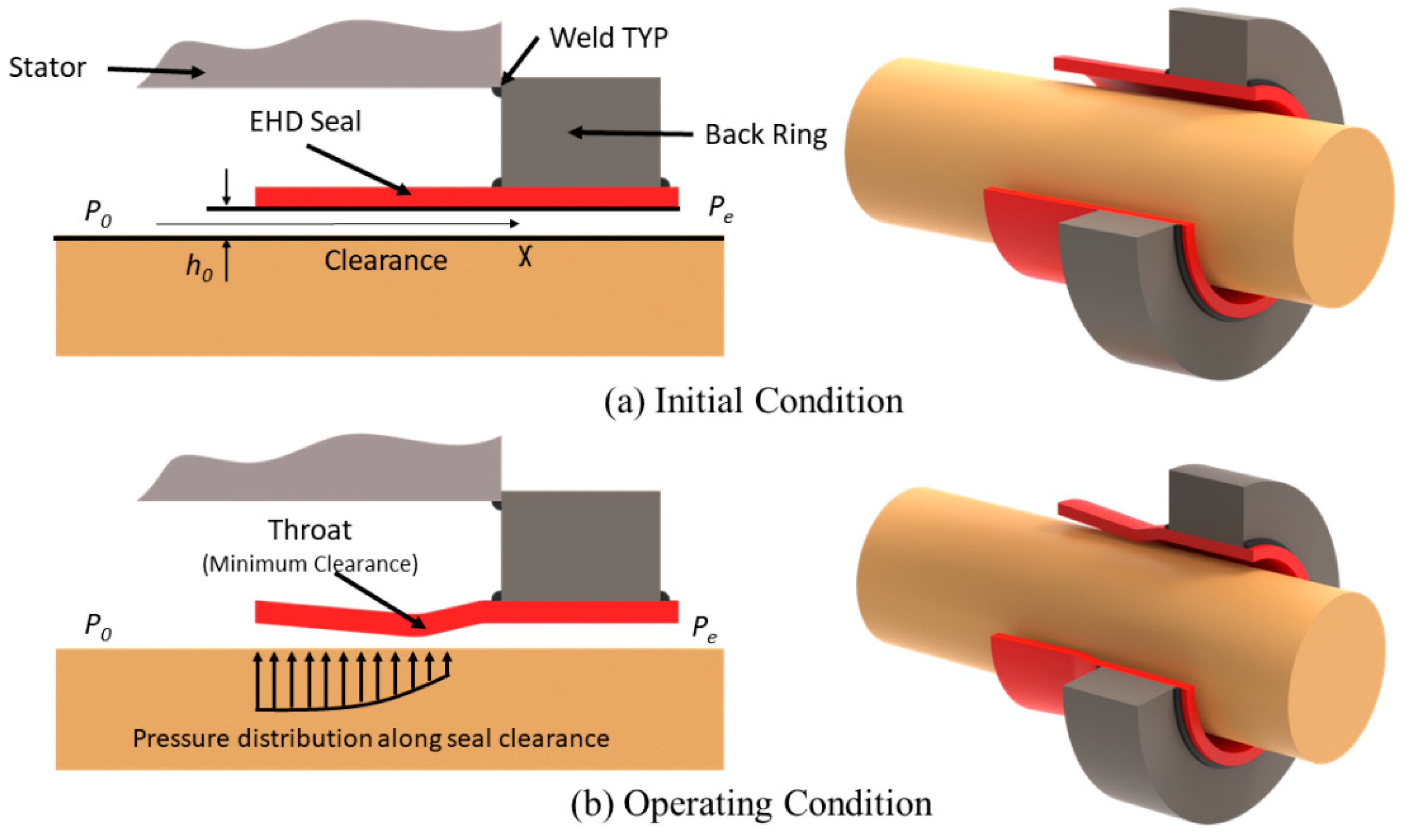
2.1. Proposed EHD Seal Design

In light of the above discussions, there will always be a sustainable minimum clearance between the seal and the rotor, which will provide an effective throttling effect to minimize leakage. The proposed EHD seal has the following potential benefits:
  • Low Leakage. The self-regulated minimum clearance throttles the sCO2 leaking flow, improving the cycle efficiency.
  • Minimal Wear. The EHD seal operates in non-contact conditions.
  • Low Cost. The simple sleeve structure results in low seal cost and minimal wear, saving maintenance costs.
  • No Stress Concentration. The EHD seal design eliminates sharp angles and stress concentration risks. The deformations on the seal will be minimal, which ensures that the seal will always stay in the linear elastic region on a typical stress-strain curve.
  • Smoother startup. The secondary seal will be integrated to the primary seal to provide sealing at the startup, which will enable active sealing for the whole operating range (0–11 MPa, from the cold start to operating conditions).

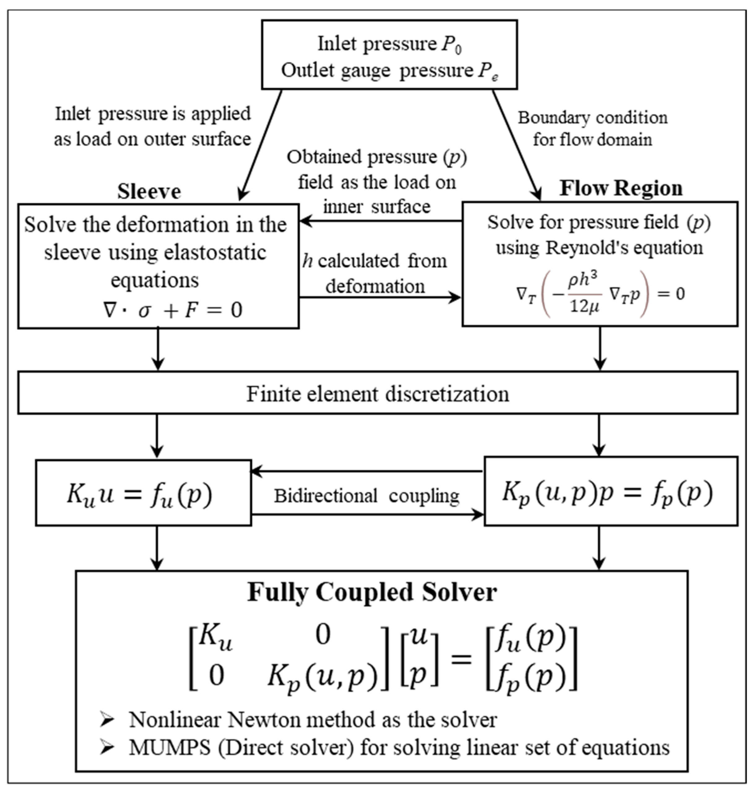
2.2. Design Methodology

In this study, only the primary seal, which is illustrated in Figure 2, has been analyzed. The flow field inside the clearance region and the deformation in the sleeve was modeled by using the Reynolds equation and the elastostatics equations, respectively.
The simulations were performed via both one-way and two-way coupled physics between the fluid and solid domains. For the one-way coupling, first, the flow field was solved. The pressure data was then transferred to the solid domain to calculate the deflection of the seal. For the fully coupled simulations, first, the fluid domain was solved. The pressure information was then imparted to the solid domain to determine the deformation on the seal, and vice versa. One might think that the analyses presented here might be easily achieved with analytical modeling. Although the flow field can be solved analytically and conveniently—when the flow is assumed to be in the axial direction only—the 2D nature of the bending makes it extremely difficult to solve the solid domain analytically. For proof-of-concept purposes, the fluid was chosen to be CO2 rather than sCO2 because the sCO2 requires two-phase flow modeling, making it very challenging, and this was left as future work. The governing equations for the fluid flow and structural deformations are detailed in this section. Before elaborating on the modeling, the assumptions for both the fluid and solid domains are summarized as follows for convenience:
-
The flow is steady. There is no sudden impact assumed between the sleeve and the rotor as it is assumed that the pressure is increased gradually.
-
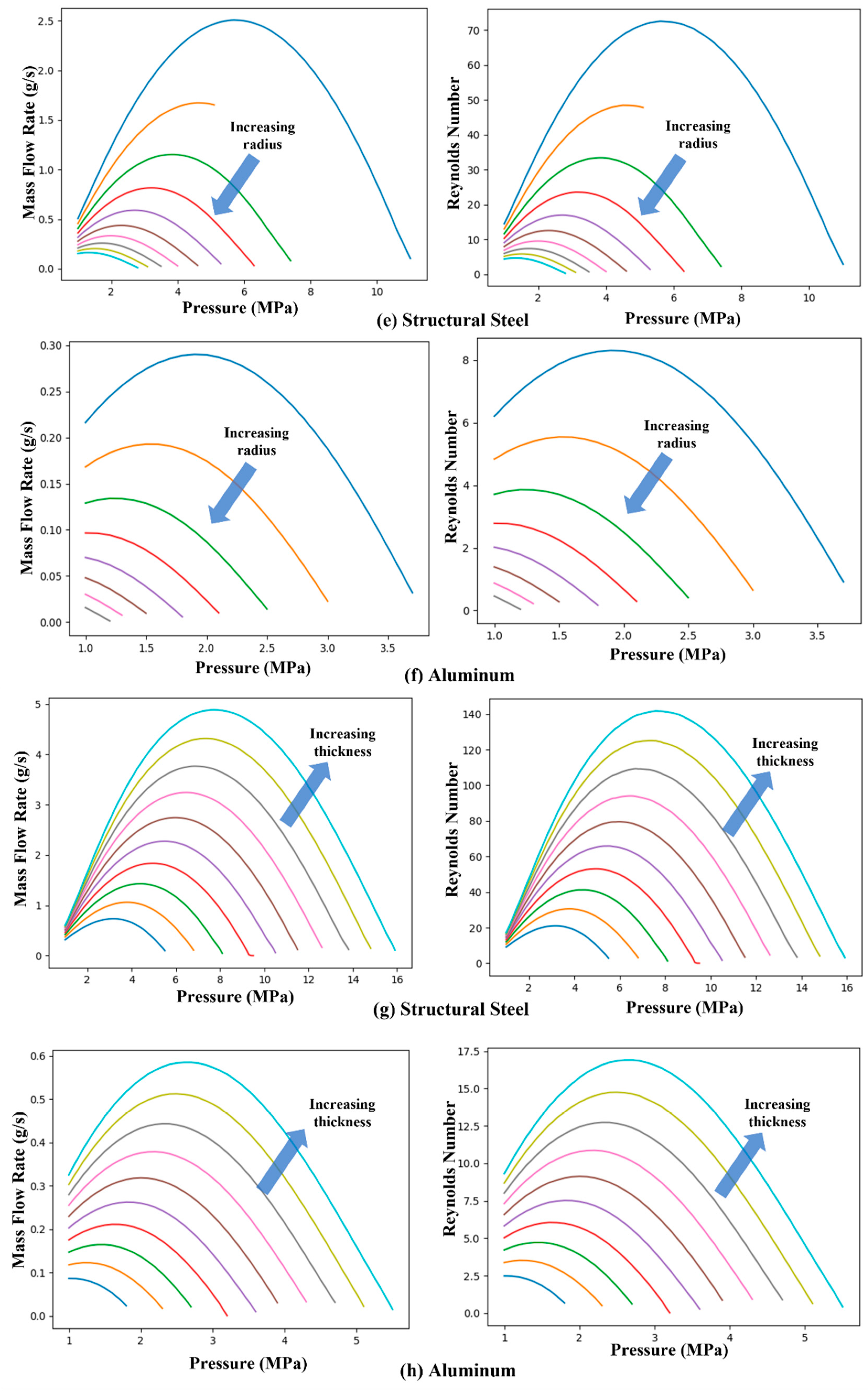
The flow is laminar. The laminar flow assumption was validated after the simulations (see Figure 11)
-
The flow is in 1D and along the shaft axis only. Because of the high-pressure differentials along the seal clearance, the very high majority of the flow occurs in the x-direction. The viscous effects due to the rotation of the sleeve are strongly dominated by the pressure differentials in the x-direction.
-
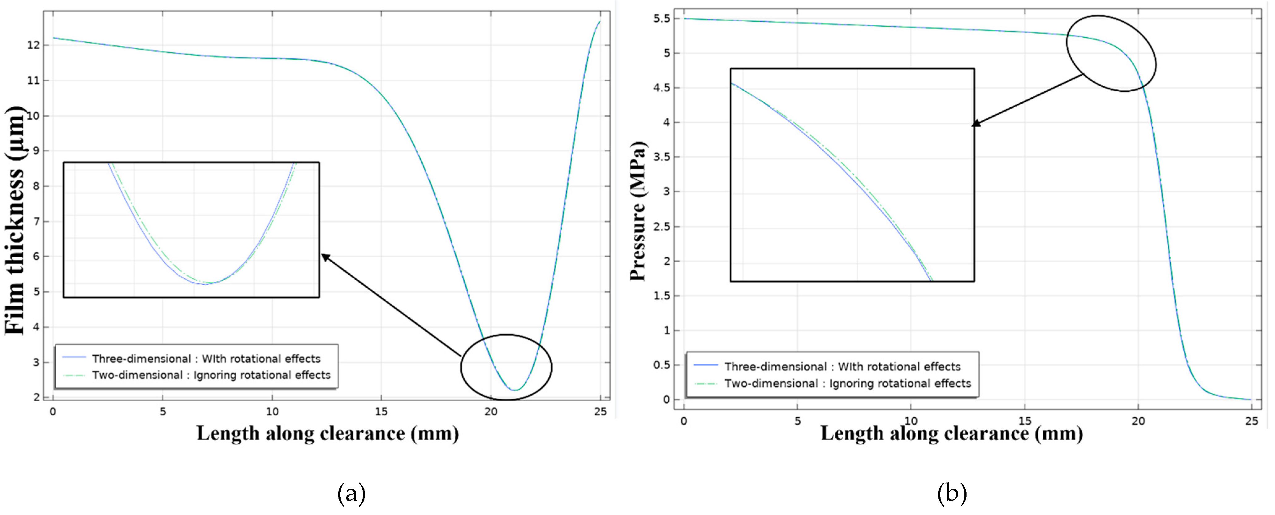
The rotational effects of the rotor are neglected since the majority of the flow is in the axial direction of the rotor and viscous effects are negligible as the working fluid is gas. Thus, both the flow and solid domains are modeled as axisymmetric, and the inertial terms are omitted from the governing equations of motion of the seal. This assumption was validated in Figure 10.
-
The back ring, the stator, and the rotor are not modeled, and the deformations of these rigid structures are assumed to be zero. This can be achieved by proper design of the seal.
-
The rotor and the sleeve were assumed to be concentric in this study. This can be achieved by proper design of the seal.
The clearance between the seal and the rotor is relatively thin compared to the sleeve thickness of the seal. The narrow clearance can be modeled as a domain, and the Navier-Stokes equations can be solved for the prescribed domain. However, it requires very fine mesh in the clearance compared to the sleeve, which will incur issues in maintaining the mesh quality due to sudden transitions of in the mesh size at the fluid-solid interface. This will also greatly increase the computational time. Instead, the narrow clearance between the seal and the rotor can be modeled as a surface, and the Reynolds equation, a simplified version of the Navier-Stokes equations for thin flow regions, can be solved conveniently. The general form of the Reynolds equation in the COMSOL handbook is given by [42]:
x ( ρ h 3   12 μ   P x ) + y ( ρ h 3   12 μ P y + ρ h 2 ( v a + v b ) ) = 0
where ρ is the density of the fluid, h is the film thickness (or the height of the clearance), μ is the dynamic viscosity, P is the pressure, va is the rotational velocity of the rotor, and vb is the rotational velocity of the sleeve. In this study, the sleeve was stationary and the effect of the rotational speed of the rotor was neglected. Hence, the governing Reynolds equation was simplified to:
d d x ( ρ h 3   12 μ   d P d x ) = 0
The fluid flowing through the clearance applies pressure on the sleeve and causes structural deformation in the sleeve. The deformation in the structure is governed by the elastodynamics equation as shown below:
  ·   σ + F = ρ s e a l u ¨
where u is the deformation occurring in the structure, σ is the Cauchy stress tensor, F is the body force, and ρ seal is the mass of the seal. is the Hamiltonian operator. In this work, the analyses were performed for steady cases, thus the acceleration term was set to zero. The body force was also neglected. Thus, Equation (3) renders into:
  ·   σ = 0
The Cauchy stress tensor is a function of the deformation, which is governed by the Hooke’s law. The simulation geometries for both the sleeve and the flow region, along with the boundary conditions and the meshing, are shown in Figure 3. The back ring, the stator, and the rotor are not modeled, and the deformations of these rigid structures are assumed to be zero. The boundary conditions at the inlet and outlet boundaries for the fluid flow along the clearance are given by:
P i n l e t = P 0
P o u t l e t = P e
where P0 is the working pressure acting on the seal and Pe is the pressure at the outlet, which is equal to the atmospheric pressure. Nonetheless, the simulation methodologies presented in this study follow a sound scientific approach and lay the foundation for future model enhancements.
The sleeve is fixed on the right end. The inner surface of the sleeve is subjected to pressure due to the fluid flow along the clearance, and the outer surface is subjected to uniformly distributed working pressure, which is equal to the inlet pressure (P0). The structural deformation of the sleeve reduces the clearance, which in turn affects the flow field, and thus, the resulting pressure distribution along the clearance. The clearance is modeled by the Thin-Film Flow module. In the Thin-Film Flow module, the thickness of the clearance is not geometrically modeled. The flow inside the clearance is modeled along the surface, and the film thickness effects on the flow are included in the flow equations. Figure 3b shows the surface along which the thin film flow is modeled, and this surface is the inner surface of the sleeve shown in Figure 3a. The horizontal lines in Figure 3 are geometrical edges, and they are used to generate the mesh.
The bidirectional coupling between the structural deformation in the sleeve and the flow fields is governed by:
  σ r = P 0   at   r = r r o t o r + t s e a l + h
  σ r = P   at   r = r r o t o r + h
h = h 0 + Δ h
where Δ h is the change in the clearance, which is equal to the structural deformation on the inner surface of the sleeve. The flowchart for the fully coupled simulations is shown in Figure 4. The pressure at the inlet of the thin film flow region is applied as a uniform pressure load on the outer surface of the sleeve with the pressure variation along the clearance applied as the pressure load along the inner surface of the sleeve. The pressure field inside the clearance is obtained by solving the Reynolds equation, which is a function of the film thickness (h). The film thickness is, in turn, affected by the sleeve deformation, which makes the problem bidirectionally coupled.
COMSOL Multiphysics is used to solve the bidirectionally coupled physics equations. COMSOL uses Finite Element methods to discretize the elastostatic and the Reynolds equations to form the respective system of equations. The force term in the elastostatic system of equations is a function of the pressure flow field. In the case of the flow field system of equations, the stiffness matrix is a function of (deformation, pressure) and the load vector is a function of pressure. To solve the bidirectionally coupled system of equations, the fully coupled solver of COMSOL is used with the nonlinear Newton’s method. The MUMPS direct solver is used for solving the linear system of equations in the linearized step of the nonlinear Newton’s method [42]. In the fully coupled solver, the Reynolds equation is solved to obtain the pressure field inside the clearance, and the pressure field is applied as the boundary load on the inner surface of the sleeve. The elastostatics equations are then solved to determine the structural deformation on the sleeve. The change in the seal clearance height is fed back to the Reynolds equation to calculate the updated pressure. This procedure was performed back and forth until convergence was achieved for the final pressure distribution in the clearance as well as the final deformation of the seal.
When carrying out CFD/FEA simulations, as a general rule of thumb, the simulation results need to be validated either with analytical solutions or experimental data. At the time of writing this manuscript, no experimental data was available for the EHD seal design. Thus, we performed an analytical case study to compare its results with the simulation data so that we can prove the fidelity of our simulations. Analytical solutions are usually available for relatively simplified models, while the solutions of the coupled, highly nonlinear partial differential equations require the use of computer simulations. Therefore, we reduced the fully coupled Fluid–Solid-Interaction (FSI) problem to a one-way coupled FSI one. Further, although the one-dimensional Reynolds equation can conveniently be applied to the flow domain, the deformation of the seal is a 2D problem, and solving a 2D elastostatics problem analytically is quite challenging. Therefore, we only compared the theoretical and computational results of the flow domain to validate our simulation methodology. Next, we discuss the analytical modeling of the flow domain.
The sleeve was made from structural steel, and carbon dioxide was used as the working fluid. The density and the dynamic viscosity of carbon dioxide are both functions of pressure and temperature. For comparison purposes, the density of the carbon dioxide was modeled by using the ideal gas equation of state, which is given by
ρ = P R T
where R is the gas constant and T is the working temperature which was considered constant in this study. The viscosity is normally a function of temperature and pressure, but for simplicity, the viscosity was considered to be constant for the analytical comparison. Integration of Equation (2), using the ideal gas equation for density and applying the boundary conditions, yields
P a n a l y t i c a l = P 0 2 + ( P e 2 P 0 2 ) x L s e a l
where the pressures are in terms of absolute pressure. The flowrate is given by
Q = ρ h 3   12 μ   d P d x
The comparisons between the analytical solutions and simulation data are presented in Figure 5 of the Results and Discussion section to validate the numerical technique used in this study.
In the fully coupled case, the pressure due to the flow affects the deformation in the sleeve, and the deformation on the sleeve affects the film thickness, which in turn affects the flow pressure. To find a solution for the fully coupled equations, numerical methods such as finite element methods are required. In this study, COMSOL Multiphysics was used to solve the fully coupled equations. The ideal gas assumption is valid for the low-density gasses, i.e., when away from the critical point region and the saturated vapor line on the P–v curves, as known from Thermodynamics. In this study, the working pressures increase up to 11 MPa, resulting in high-density carbon dioxide, where its behavior deviates from the ideal gas, and the ideal gas equation does not precisely describe this gas behavior. The errors associated with the use of the ideal gas equation can be mitigated by introducing the compressibility factor. To include the effect of the compressibility factor, the density data, as a function of pressure and temperature, was imported from the NIST’s lookup tables [43] and was used in place of the ideal gas equation.
As mentioned earlier, COMSOL Multiphysics is used in this study for solving the physics equations. COMSOL Multiphysics is a computational tool that discretizes single or coupled Multiphysics equations into a system of equations using finite element methods and provides different direct/iterative solvers to solve the resulting system of equations [42]. The tool provides the option of choosing different shape functions for discretization. More details about the physics of Thin-film Flow, Solid Mechanics, and Fluid-Structure-Interaction modules can be found in [44,45].

3. Results and Discussions

This section presents the results obtained from the numerical simulation for different flow conditions using COMSOL Multiphysics. Table 1 lists the geometric and material properties that were used in the simulations. First, the numerical solution obtained using COMSOL is compared with the analytical solution. Next, the results of the proof-of-concept studies are presented followed by the parametric studies.

3.1. Analytical Solution of a Simplified Case

For the analytical solution, only flow equations are considered with the ideal gas equation, and the effect of the compressibility factor on the flow is neglected. CO2 is used as the working fluid. Figure 5 shows the comparisons between the analytical and simulation results of the pressure along the seal clearance for one-way coupling, with the pressures decreasing quadratically along the seal length. The simulation results matched the analytical solution, which confirmed our simulation methodology.

3.2. Proof-of-Concept Studies

For proof-of-concept purposes, the seal material was selected to be structural steel. However, as discussed in Section 3.3, the aluminum seal material was also investigated. The working fluid was chosen to be CO2. As known, the density and viscosity of CO2 change with pressure and temperature. Considering the pressure range is taken to be 0.1 to 11 MPa for proof-of-concept purposes, the viscosity and density data, as a function of pressure and temperature, was extracted from the NIST’s lookup tables and was imported into COMSOL to include the effect of the compressibility factor [43]. The outlet boundary condition for the fluid flow is zero-gauge pressure, and the inlet boundary condition is the working pressure. The pressure distribution and deformations of the sleeve design were solved for varying working (inlet) pressures. As for the meshing, a swept mesh scheme was used. First, a mapped mesh was used to mesh the outer surface of the cylinder with a 1 mm element size, with the surface mesh swept along the thickness, generating four layers of elements. A total of 20,160 hexahedra mesh elements were generated with 26,100 vertices, maintaining the minimum mesh quality of 0.99 and the element volume ratio of 0.99. Quadratic elements were used for finite element discretization.
The fully coupled analyses are extremely difficult with analytical approaches. Therefore, we conveniently achieved the fully coupled solutions with the help of the Thin-Film Flow and Solid Mechanics modules of COMSOL. Figure 6 shows the pressure variation of the fluid along the clearance between the rotor and the seal for the inlet working pressure of 5 MPa obtained from the fully coupled simulation. The left and right sides are the inlet and outlet, respectively. As shown in Figure 6, the pressure is decreasing along the flow direction with the reduction rate being much prominent closer to the exit. This throttling effect of the seal is analogous to a typical throttling valve, where a similar pressure variation is observed across the valve. Depending on the strength of the throttling effect, the level of the recovered pressure varies.
The deformation of the seal and the film thickness for varying inlet pressures and the von Mises stress plot at P0 = 5 MPa are shown in Figure 7. The film thickness is the difference between the initial clearance and the radial deformation of the inner surface of the sleeve. The film thickness is 0.0127 mm at the left end, and it decreases to a minimum value before increasing to the initial clearance at the fixed end on the right. The location of the minimum film thickness shifts towards the fixed end of the sleeve and increases nonlinearly with the working pressure. The sleeve deformation results proved our hypothesis, which was discussed in Section 2.1. The throttling effect is clearly visualized in Figure 7a. It is also interesting to note that the throttling effect becomes stronger with increasing inlet pressures. The deformation of the seal is also reflected on the von Mises stress plot, clearly depicting the throttling effect in 3D view (Figure 7b). The inner surface of the sleeve was subjected to varying fluid pressures, and the outer surface was under constant working pressure. As expected, the stress is maximized at the fixed end.
The mass flow rate data, obtained from the fully coupled multiphysics simulation, for the design conditions listed in Table 1 are given in Figure 8. The inlet pressure ranged from 0.1 MPa to 11 MPa. The mass flow rate (also referred as the leakage rate) is increasing with increasing inlet pressures and peaks at around 5.5 MPa, before decaying to lower values at higher inlet pressures. This quadratic behavior of the mass flow rate can become advantageous for sCO2 power generation applications, where the inlet pressures can reach and exceed 11 MPa. Similar leakage behavior was observed in [46,47,48,49], where the researchers investigated the Morrison and Parry seals. Although the Morrison and Parry seals differ in seal configuration and application, the sealing mechanism and the underlying physics are considered to be the similar for both. Therefore, the findings of the current study are supported by the data reported in [46,47,48,49].
It should be noted that the thermal effects in the solid domain are neglected for simplicity. Nevertheless, the goal of this paper was to prove the working mechanism of the proposed seal concept by using fundamental physics and modern engineering tools to lay a foundation for future model developments (see Section 4 for further discussion).
As a general rule, a mesh independency study must be conducted to prove that the simulation results are not changing with decreasing mesh sizes or increasing number of mesh elements. Figure 9 shows the results of the mesh independency study using quadratic elements for FEM discretization and using 1, 0.9, 0.8, and 0.7 mm mesh sizes along the seal length. The pressure variation and the film thickness results did not change beyond the mesh element size of 1 mm.
The rotor and the sleeve were assumed to be concentric in this study. Thus, the effects of rotational motion were assumed to be negligible since the majority of the flow would be in the axial direction of the rotor. Nonetheless, we carried out a comparison study to reveal the effects of the rotations on seal behavior. The comparisons between the simulation results of 3D with rotational effects, 3D without rotational effects, and 2D without rotational effects are presented in Figure 10. Apparently, the results are overlapped. Thus, it was concluded that it is safe to carry out the simulations in 2D by ignoring the rotational effects, which helped save significant computational time and resources. In fact, this is one of the apparent advantages of COMSOL’s Thin-Film Flow module, specifically, that simulations can be conducted with minimal time and effort without loss of accuracy. In this study, a single simulation took less than 5 seconds to converge.
Figure 10. Comparisons of the simulations results for P0 = 5.5 MPa: (a) 3D with rotational effects versus 2D without rotational effects and (b) 3D without rotational effects versus 2D without rotational effects.
Applsci 12 09501 g010

3.3. Parametric Studies

To see the effects of significant design parameters on seal performance, we performed parametric sweep analyses. The parameters that we considered included seal material, seal clearance, seal length, seal radius, and seal thickness. These parameters along with their ranges are listed in Table 2. Each range included 10 data points.
It should be noted that when a parameter of interest was varied, all else remained at their design values listed in Table 1, except for the inlet pressure, P0. The effects of the seal material, seal clearance, seal length, seal radius, and seal thickness on the mass flow rate are given in Figure 11 in a mass flow rate vs. parameter range format. It can be seen that the mass flow rate is increasing with increasing values of clearance (Figure 11a,b), which makes sense since the larger clearances reduce the flow resistance, increasing the mass flow rate for the same inlet pressure. In other words, less energy is spent to overcome the frictional effects in the clearance. When comparing the steel and aluminum material cases, it can be seen that the mass flow rate values are higher for the steel material, which agrees with our intuitions because the elastic modulus of steel is higher than that of aluminum, making the steel seal stiffer to bend.
As for the effect of seal length, the mass flow rate is decreasing with increasing seal length (Figure 11c,d), which is expected. This is because the longer the seal becomes, the larger the frictional losses are, reducing the mass flow rate. Again, the mass flow rate values were higher for the steel seal due to the same reason discussed above.
Regarding the effect of rotor radius on the mass flow rate, as the rotor radius increases, the mass flow rate decreases (Figure 11e,f). This also agrees with our expectations since the thin-walled cylinder effect becomes stronger with increasing rotor diameters, reducing the effective stiffness of the seal. This, in turn, increases the bending of the seal, resulting in lower mass flow rates. Compared to the aluminum case, steel material resulted in larger mass flow rates because it has a higher elastic modulus and thus stiffness compared to aluminum.
Lastly, the mass flow rate increases with increasing seal thicknesses (Figure 11g,h). This is reasonable because the larger seal thicknesses reduce the thin-walled cylinder effect, reducing the deformations on the seal, and thus increasing the mass flow rate. Again, compared to aluminum, the steel material resulted in larger mass flow rates because of its greater elastic modulus compared to aluminum. It should be noted that due to convergence issues that occurred during the simulations, some of the mass flow rate plots do not have data points at high inlet pressure values. Nonetheless, this did not obscure the trends observed and discussed above. Such trends can clearly be seen in Figure 11a–h.
Figure 11. Variation of mass flow rates along with the associated Reynolds numbers for (a,b) increasing clearance for structural steel and aluminum; (c,d) increasing length for structural steel and aluminum; (e,f) increasing radius for structural steel and aluminum; (g,h) increasing thickness for structural steel and aluminum. The ranges of the parameters are listed in Table 2, and the simulations were conducted at 10 equal intervals in respective ranges.
Applsci 12 09501 g011aApplsci 12 09501 g011b
To validate the assumptions listed in Section 2.2, the Reynolds numbers for all simulations are listed on the right side in Figure 11a–h. For the flow through the annular ring, the Reynolds number is given by
Re = ρ V h μ
where ρ is the density of the fluid, V is the velocity of the fluid, h is the height of the clearance, and   μ is the dynamic viscosity of the fluid. As can be seen, the Reynolds number was below 2000 in all cases, where the Reynolds equation can safely be used. However, it should be note that despite the accuracy, simplicity, and very fast convergence time the present model is valid only under the restrictive assumptions listed in Section 2.1. As such, when employed, proper care must be exercised.

4. Conclusions

This study presented a foundational physics-based simulation approach to describe the behavior of a seal design. The proposed approach included fully coupled Fluid–Solid Interaction (FSI) simulations that were performed by using COMSOL’s Thin-Film Flow and Solid Mechanics modules. The simulation methodology was verified by analytical solutions for the flow domain, only because there were no available analytical solutions for such complicated FSI phenomena. The simulation results were also supported by the existing literature. The flow properties were imported from the NIST’s website for the most accurate results. Nonetheless, this study did not involve phase transition effects that are likely to happen in sCO2 conditions. This was beyond the scope of this study. Moreover, a parametric analysis was carried out to determine the effects of important design parameters on the leakage rate. The main conclusions of this study can be summarized as follows. A fully coupled physics-based model using modern engineering tools was developed. The constriction behavior of the seal was successfully demonstrated, which can reduce the mass flow rate. The mass flow rate of the EHD seal increases with increasing inlet pressures, reaching a peak at a certain value and then starting to decay to lower values. The maximum and minimum leakages were calculated to be 2.25 g/s and 0.1 g/s at P = 5.5 MPa and P = 11 MPa for the design seal, respectively. The numerical results of the parametric sweep analyses quantitatively showed the effects of the clearance, seal length, seal radius, and seal thickness based on two different materials. The mass flow rate increased with increasing values of seal clearance and thickness and decreased with increasing values of seal length and rotor radius, which agreed with the expectations. The model presented in this paper lays a solid foundation for further simulations to capture the seal behavior more accurately.
In relation to future work, we will attempt to investigate the following. In the present study, the high Ma number effects in the clearance were neglected. As part of any future work, we will attempt to enhance the model by incorporating such effects, particularly for larger differential pressure conditions. We will design and fabricate a 2” static test rig to demonstrate the EHD seal experimentally.

Author Contributions

Methodology, S.C., K.R.L., S.L. and H.X.; Project administration, S.C. and H.X.; Resources, S.C. and H.X.; Software, S.C.; Supervision, S.C.; Validation, K.R.L., S.L., H.X. and J.T.; Visualization, K.R.L. and M.F.H.; Writing—original draft, S.C., M.F.H. and K.R.L.; Writing—review & editing, K.R.L., S.C., S.L., M.F.H., H.X. and J.T. All authors have read and agreed to the published version of the manuscript.

Funding

This work has been financially supported by the U.S. Department of Energy (DOE) STTR (Small Business Technology Transfer Research) Phase I and II grants under Grant No. DE-SC0020851.

Institutional Review Board Statement

Not applicable.

Informed Consent Statement

Not applicable.

Data Availability Statement

Not applicable.

Acknowledgments

This work has been financially supported by the U.S. Department of Energy (DOE) STTR (Small Business Technology Transfer Research) Phase I and II grants under Grant No. DE-SC0020851. Sevki Cesmeci and Hanping Xu serve as the Principal Investigator and Business Official for the grant, respectively. DOE’s support is gratefully acknowledged. Disclaimer: This manuscript reflects the views of the author(s) only and does not necessarily reflect the views or opinions of DOE. The intellectual property of the proposed seal concept is protected under Patent No. 63/200,712, “Clearance Seal with An Externally Pressurized Sleeve”.

Conflicts of Interest

The authors declare no conflict of interest.

Nomenclature

P0Inlet pressurePa
PeOutlet pressurePa
ρDensityKg/m3
hFilm thickness/clearancem
μDynamic viscosityPa s
pPressurePa
vaRotational velocity of the rotorm/s
vbRotational velocity of the sleevem/s
TTemperatureK
σCauchy stress tensorN/m2
FBody force per unit volumeN/m3
u Displacement/deformation in the structurem
RGas constantkJkg−1·K−1
Hamiltonian operator-
Δ h Change in clearancem
rRadiusm
rrotorRotor radiusm
t s e a l EHD seal thicknessm
LsealEHD seal lengthm
xLength along the clearancem
FEMFinite Element Method-

References

  1. Ho, C.K.; Carlson, M.; Garg, P.; Kumar, P. Technoeconomic Analysis of Alternative Solarized s-CO2 Brayton Cycle Configurations. J. Sol. Energy Eng. Trans. ASME 2016, 138, 5. [Google Scholar] [CrossRef]
  2. Neises, T.; Turchi, C. A comparison of supercritical carbon dioxide power cycle configurations with an emphasis on CSP applications. Energy Procedia 2014, 49, 1187–1196. [Google Scholar] [CrossRef]
  3. Wright, S.A.; Fuller, R.; Pickard, P.S.; Vernon, M.E.; Radel, R.F.; Vernon, M.E. Supercritical CO2 Brayton Cycle Power Generation Development Program And Initial Test Results. In Proceedings of the ASME Power Conference, Power 2009, Albuquerque, NM, USA, 21–23 July 2009; Power 2009-81081. pp. 573–583. [Google Scholar]
  4. Turchi, C.S.; Neises, T.W.; Wagner, M.J. Thermodynamic Study of Advanced Supercritical Carbon Dioxide Power Cycles for Concentrating Solar Power Systems. J. Solar Energy Eng. 2013, 135, 1–7. [Google Scholar] [CrossRef]
  5. Justak, J.F.; Doux, C. Self-Acting Clearance Control for Turbine Blade outer Air Seals. ASME Turbo Expo 2009, 3, 9. [Google Scholar] [CrossRef]
  6. Dinc, S.; Demiroglu, M.; Turnquist, N.; Mortzheim, J.; Goetze, G.; Maupin, J.; Hopkins, J.; Wolfe, C.; Florin, M. Fundamental design issues of brush seals for industrial applications. Proc. ASME Turbo Expo 2001, 3, 1–10. [Google Scholar] [CrossRef]
  7. Schlumberger, A. Film Riding Seals for Rotary Machines. U.S. Patent 9587746B2, 6 February 2014. [Google Scholar] [CrossRef]
  8. Salehi, M.; Heshmat, H. On the fluid flow and thermal analysis of a compliant surface foil bearing and seal. Tribol. Trans. 2000, 43, 318–324. [Google Scholar] [CrossRef]
  9. Ferguson, J.G. Brushes As High Performance Gas Turbine Seals. In Turbo Expo: Power for Land, Sea, and Air, Proceedings of the Gas Turbine and Aeroengine Congress, 6–9 June 1988, Amsterdam, The Netherlands; American Society of Mechanical Engineers: New York, NY, USA; ISBN 978-0-7918-7919-1. [CrossRef]
  10. Zhao, H.; Su, H.; Chen, G. Analysis of total leakage of finger seal with side leakage flow. Tribol. Int. 2020, 150, 106371. [Google Scholar] [CrossRef]
  11. Heshmat, J.L.C.H.; Walton, J. Technology Readiness of 5th and 6th Generation Compliant Foil Bearing for 10 MWE S-CO2 Turbomachinery Systems. In Proceedings of the 6th International Supercritical CO2 Power Cycles Symposium, Pittsburgh, PA, USA, 27–29 March 2018; pp. 1–29. Available online: https://www.researchgate.net/publication/324227375%0A“Technology (accessed on 9 September 2022).
  12. Moore, J.; Lawson, S. Development of Oxy-Fuel Combustion Turbines with CO2 Dilution for Supercritical Carbon Dioxide Based Power Cycles. 2018; p. 38. Available online: https://netl.doe.gov/sites/default/files/2019-01/FE0031620-Kickoff.pdf (accessed on 9 September 2022).
  13. Trivedi, D.; Bidkar, R.A.; Wolfe, C.; Zheng, X. Film-stiffness characterization for supercritical CO2 film-riding seals. Proc. ASME Turbo Expo 2018, 5B-2018, 1–10. [Google Scholar] [CrossRef]
  14. Laxander, A.; Fesl, A.; Hellmig, B. Development And Testing of Dry Gas Seals For Turbomachinery In Multiphase CO2 Applications. In Proceedings of the 3rd European Supercritical CO2 Conference, Paris, France, 19–20 September 2019; pp. 1–12. [Google Scholar] [CrossRef]
  15. Chapman, P. A High Performance Dry Gas Seal for High Temperature and Pressure Supercritical CO2 Power Cycles. 2019. Available online: https://www.osti.gov/biblio/1506975 (accessed on 9 September 2022).
  16. Bidkar, R.A.; Sevincer, E.; Wang, J.; Thatte, A.M.; Mann, A.; Peter, M.; Musgrove, G.; Allison, T.; Moore, J. Low-Leakage Shaft-End Seals for Utility-Scale Supercritical CO2 Turboexpanders. J. Eng. Gas Turbines Power 2017, 139, 1–8. [Google Scholar] [CrossRef]
  17. Dowson, D. A generalized Reynolds equation for fluid-film lubrication. Int. J. Mech. Sci. 1962, 4, 159–170. [Google Scholar] [CrossRef]
  18. Gong, R.Z.; Li, D.Y.; Wang, H.J.; Han, L.; Qin, D.Q. Analytical solution of Reynolds equation under dynamic conditions. Proc. Inst. Mech. Eng. Part J J. Eng. Tribol. 2016, 230, 416–427. [Google Scholar] [CrossRef]
  19. Wu, S.R. A penalty formulation and numerical approximation of the Reynolds-Hertz problem of elastohydrodynamic lubrication. Int. J. Eng. Sci. 1986, 24, 1001–1013. [Google Scholar] [CrossRef]
  20. Morris, S.; Sellier, M.; al Behadili, A.R. Comparison of lubrication approximation and Navier-Stokes solutions for dam-break flows in thin films. arXiv 2017, arXiv:1708.00976. [Google Scholar]
  21. Tibos, S.M.; Georgakis, C.; Harvey, K.; Teixeira, J.A. Detailed Study on Stiffness and Load Characteristics of Film-Riding Groove Types Using Design of Experiments. J. Eng. Gas Turbines Power 2017, 139, 9. [Google Scholar] [CrossRef]
  22. Conry, T.F.; Wang, S.; Cusano, C. A roynolds-eyring equation for elastohydrodynamic lubrication in line contacts. J. Tribol. 1987, 109, 648–654. [Google Scholar] [CrossRef]
  23. Habchi, W.; Eyheramendy, D.; Bair, S.; Vergne, P.; Morales-Espejel, G. Thermal elastohydrodynamic lubrication of point contacts using a Newtonian/generalized Newtonian lubricant. Tribol. Lett. 2008, 30, 41–52. [Google Scholar] [CrossRef]
  24. Habchi, W.; Eyheramendy, D.; Vergne, P.; Morales-Espejel, G. A full-system approach of the elastohydrodynamic line/point contact problem. J. Tribol. 2008, 130, 1–10. [Google Scholar] [CrossRef]
  25. Habchi, W. A numerical model for the solution of thermal elastohydrodynamic lubrication in coated circular contacts. Tribol. Int. 2014, 73, 57–68. [Google Scholar] [CrossRef]
  26. Björling, M.; Habchi, W.; Bair, S.; Larsson, R.; Marklund, P. Towards the true prediction of EHL friction. Tribol. Int. 2013, 66, 19–26. [Google Scholar] [CrossRef]
  27. Habchi, W.; Demirci, I.; Eyheramendy, D.; Morales-Espejel, G.; Vergne, P. A finite element approach of thin film lubrication in circular EHD contacts. Tribol. Int. 2007, 40, 1466–1473. [Google Scholar] [CrossRef]
  28. Paulson, N.R.; Sadeghi, F.; Habchi, W. A coupled finite element EHL and continuum damage mechanics model for rolling contact fatigue. Tribol. Int. 2017, 107, 173–183. [Google Scholar] [CrossRef]
  29. Cesmeci, S.; Hassan, R.; Hassan, M.F.; Ejiogu, I.; DeMond, M.; Xu, H.; Tang, J. An Innovative Elasto-Hydrodynamic Seal Concept for Supercritical CO2 Power Cycles. In Proceedings of the ASME 2021 Power Conference, Virtual, Online, 20–21 July 2021; p. V001T04A002. [Google Scholar] [CrossRef]
  30. Lyathakula, K.R.; Cesmeci, S.; Hassan, M.F.; Xu, H.; Tang, J. A Proof-of-Concept Study of a Novel Elasto-Hydrodynamic Seal for Supercritical CO2 Turbomachinery Applications. In Proceedings of the ASME 2022 Power Conference, Pittsburgh, PA, USA, 18–19 July 2022. [Google Scholar] [CrossRef]
  31. Lyathakula, K.R.; Cesmeci, S.; DeMond, M.; Xu, H.; Tang, J. Physics-Informed Deep Learning-Based Modeling of a Novel Elastohydrodynamic Seal for Supercritical CO2 Turbomachinery. In Proceedings of the ASME 2022 Power Conference, Pittsburgh, PA, USA, 18–19 July 2022. [Google Scholar] [CrossRef]
  32. Peterson, W.; Russell, T.; Sadeghi, F.; Berhan, M.T. A Strongly Coupled Finite Difference Method–Finite Element Method Model for Two-Dimensional Elastohydrodynamically Lubricated Contact. J. Tribol. 2020, 142, 1–8. [Google Scholar] [CrossRef]
  33. Feldermann, A.; Neumann, S.; Jacobs, G. CFD simulation of elastohydrodynamic lubrication problems with reduced order models for fluid–structure interaction. Tribol.—Mater. Surfaces Interfaces 2017, 11, 30–38. [Google Scholar] [CrossRef]
  34. Lohner, T.; Ziegltrum, A.; Stemplinger, J.P.; Stahl, K. Engineering Software Solution for Thermal Elastohydrodynamic Lubrication Using Multiphysics Software. Adv. Tribol. 2016, 2016, 6507203. [Google Scholar] [CrossRef]
  35. Bearings, H.; Theory, P. A CFD-Based Frequency Response Method Applied in the Determination of Dynamic Coefficients of hydrodynamic bearings. Part 1: Theory. Lubricants 2019, 7, 23. [Google Scholar] [CrossRef] [Green Version]
  36. Chen, Q. Analysis of Soft- Elastohydrodynamic Lubrication Line Contacts on Finite Thickness. J. Tribol. 2018, 140, 1–8. [Google Scholar] [CrossRef]
  37. Sellier, M.; Lee, Y.C.; Thompson, H.M.; Gaskell, P.H. Thin film flow on surfaces containing arbitrary occlusions. Comput. Fluids 2009, 38, 171–182. [Google Scholar] [CrossRef]
  38. Tauviqirrahman, M.; Jamari, J.; Susilowati, S.; Pujiastuti, C.; Setiyana, B.; Pasaribu, A.H.; Ammarullah, M.I. Fluid on a Heterogeneous Slip/No-Slip Journal Bearing System Based on CFD-FSI Method. Fluids 2022, 7, 225. [Google Scholar] [CrossRef]
  39. Xu, H.; Lei, T. A ringless high pressure moving seal up to 1200 mpa. Tribol. Trans. 1994, 37, 767–770. [Google Scholar] [CrossRef]
  40. Xu, H.P.; Wong, P.L.; Zhang, Z.M. An EHL Analysis of an All-Metal Viscoelastic High-Pressure Seal. J. Tribol. 1999, 121, 916–920. [Google Scholar] [CrossRef]
  41. Wong, P.L.; Xu, H.; Zhang, Z. Performance evaluation of high pressure sleeve seal. Wear 1997, 210, 104–111. [Google Scholar] [CrossRef]
  42. COMSOL. COMSOL Multiphysics User’s Guide; COMSOL: Stockholm, Sweden, September 2005. [Google Scholar]
  43. Lemmon, M.O.W.; Eric, B.; Ian, H.; Huber, M.; McLinden, L. Thermophysical Properties of Fluid Systems; National Institute of Standard & Technology: Gaithersburg, MD, USA, 2022. [Google Scholar] [CrossRef]
  44. COMSOL. Structural Mechanics Module User’s Guide, COMSOL MultiphysicsR v. 5.2 a; COMSOL AB: Stockholm, Sweden; Available online: www.comsol.com (accessed on 9 September 2022).
  45. COMSOL. CFD Modules User’s Guide, COMSOL MultiphysicsTM v. 5.4.; COMSOL AB: Stockholm, Sweden, 2018. [Google Scholar]
  46. Pick, R.J.; Harris, H.D. Morrison and Parry Seals for Water Pressures up to 345 MPa. J. Pressure Vessel Technol. 1980, 102, 84–89. [Google Scholar] [CrossRef]
  47. Parry, J.S.C. University of Bristol, Development of Reciprocating Seals for Very High Pressures (45000 lb per in2). In Proceedings of the Third International Conference on Fluid Sealing, Cambridge, England, 1 January 1967. P.C-6-69-c6-80. [Google Scholar]
  48. Dean, T.J.; Elligsen, R.A.; Mohaupt, U.H. High Pressure Sealing Characteristics of Metallic Sleeve Seals. MRS Online Proc. 1984, 22, 249–252. [Google Scholar] [CrossRef]
  49. Pick, D.J.B.R.J. Dimensional Parameters Influencing the Behavior of the Morrison Unsupported Area Seal. J. Eng. Industry 1970, 92, 755–758. [Google Scholar] [CrossRef]
Figure 1. Working mechanism of the proposed seal concept: (a) initial condition and (b) operating condition.
Applsci 12 09501 g001
Figure 2. Working mechanism of the proposed EHD seal: (a) initial condition and (b) operating condition.
Applsci 12 09501 g002
Figure 3. (a) Sleeve domain and (b) flow surface along with boundary conditions and meshing.
Applsci 12 09501 g003
Figure 4. Flowchart for fully coupled simulations.
Applsci 12 09501 g004
Figure 5. Comparison of the analytical solution of the pressure field with simulation for different inlet pressure conditions for the one-way coupling. The continuous lines are the results obtained from the numerical simulation, and the plots with the asterisk marker represent the analytical solution.
Applsci 12 09501 g005
Figure 6. (a) Line plot of the pressure variation along the clearance for various inlet pressure conditions between 1 MPa and 11 MPa in intervals of 1 MPa. The inlet pressure value for each curve is the value on the corresponding curve at x = 0. (b) Surface plot of the pressure variation in the thin film between the rotor and sleeve at P0 = 5 MPa.
Applsci 12 09501 g006
Figure 7. (a) Variation of radial displacement of the sleeve and the film thickness along the sleeve length at different inlet pressure conditions between 0.2 MPa and 11 MPa in increments of 1 MPa. (b) von Mises stress on the inner surface of the sleeve for P0 = 5 MPa.
Applsci 12 09501 g007
Figure 8. Variation of the mass flow rate for different inlet pressure conditions, between 0.1 MPa and 11 MPa, obtained from the fully coupled multiphysics simulations at the design conditions listed in Table 1.
Applsci 12 09501 g008
Figure 9. Mesh independency study using linear and quadratic shape functions for FEM discretization, and using 1, 0.9, 0.8, and 0.7 mm mesh sizes at a film thickness of 0.0127 mm and an inlet pressure condition of 5.5 MPa. The solution changes with decreasing mesh size with a linear shape function, while the results with the quadratic element show that the solution is mesh-independent.
Applsci 12 09501 g009
Table 1. Geometric and material properties.
Property/ParameterValue
Rotor radius (rrotor)25.4 mm
EHD seal thickness (tseal)0.5 mm
EHD seal length (Lseal)25.0 mm
Initial clearance (h0)0.0127 mm
Dynamic viscosity of CO2 (µ)f(P, T)
Young’s modulus of the steel seal (E)2 × 10¹¹ N/m2
Young’s modulus of the aluminum seal (E)70 × 109 N/m2
Density of CO2 (ρ)f(P, T)
Working pressure (P0)Varying
Ambient pressure (Pe)0 Gauge
Gas constant of CO20.1889 kJ/(kg·K)
Table 2. Parameters with their respective ranges.
ParameterRange
EHD seal initial clearance, h00.00635–0.0254 mm
EHD seal length, Lseal12.7–38 mm
Rotor radius, rrotor25.4–50.8 mm
EHD seal thickness, tseal0.25–0.75 mm
Publisher’s Note: MDPI stays neutral with regard to jurisdictional claims in published maps and institutional affiliations.

