Article

Study of Novel Punched-Bionic Impellers for High Efficiency and Homogeneity in PCM Mixing and Other Solid-Liquid Stirs

1
College of Mechanical Engineering, Zhejiang University of Technology, Hangzhou 310023, China
2
Innovation Research Institute of Shengzhou, Zhejiang University of Technology, Shengzhou 312400, China
*
Author to whom correspondence should be addressed.
Appl. Sci. 2021, 11(21), 9883; https://doi.org/10.3390/app11219883
Submission received: 27 September 2021 / Revised: 10 October 2021 / Accepted: 19 October 2021 / Published: 22 October 2021

Abstract

:
Improvement of stirring performance is one of the primary objectives in solid–liquid mixing processes, such as the preparation of phase change materials (PCMs) for energy saving in refrigeration and heat pump systems. In this paper, three novel impellers are proposed: pitched-blade punched turbine (PBPT), bionic cut blade turbine (BCBT) and bionic cut punched blade turbine (BCPBT). An experimental test was conducted to validate the stirring system model based on the Eulerian–Eulerian method with the kinetic theory of granular flow. Then the performance of the novel impellers was predicted, studied, and compared. The outcomes indicate that a novel impeller, specifically BCPBT, can effectively suspend particles and dramatically reduce power consumption. A better solid–liquid suspension quality was obtained with an aperture diameter of 8 mm and aperture ratio of 13%. Within the range of impeller speeds and liquid viscosity studied in this this paper, higher impeller speeds and more viscous liquids are more conducive to particle dispersion. One of the most important contributions of this work lies in the design of novel impellers, an extent of energy conservation to 17% and efficient mixing was achieved. These results have reference significance for improving the energy efficiency of temperature regulation systems.

1. Introduction

Air conditioning, refrigeration and heat pump systems have been widely used in the civil, military and industrial fields, for example, the application of heat pump systems in the cold climate of northern China [1,2]. Building energy consumption accounts for 23% of global primary energy and 30% of global electricity. To improve the energy efficiency of refrigeration/heat pump systems, phase change materials (PCMs) for thermal energy storage have attracted more and more attention [3,4], as they can help smooth energy supply and consumption.
In particular, it has been pointed out that organic solid–liquid PCMs have great practical application value, and can be used in building air conditioning, underground heating and refrigeration systems [5,6]. However, the thermal conductivity of organic solid–liquid PCMs is low and needs to be increased by adding thermal conductive particles. In the preparation processes of PCM mixture, the key is to ensure a degree of homogeneity throughout the vessel, prevent solid accumulation and maximize the contact area between solid and liquid phases [7,8,9]. Thus, most of the methods for the mixing of thermal conductive particles and PCMs needs high efficiency stirring. For example, the melt blending method, one of the most favorable manufacturing methods for solid–liquid PCMs due to its potential in large-scale production, is to directly add the thermally conductive filler to the molten polymer, mix it evenly in the stirred tank, and then solidify it to form the product (Figure 1). The mixing quality in the stirring process is directly related to the performance of solid–liquid PCMs, which affects the energy utilization efficiency. At present, various small batches production of solid–liquid PCMs have been widely adopted, however, large-scale production is still in its infancy. The most important reason is the lack of manufacturing technology and equipment suitable for mass production. Therefore, a study of stirring equipment for mixing with high efficiency, rapidity, and homogeneity is important, and can also be helpful for solid–liquid mixing in other fields.
Pitched blade turbine (PBT) has been extensively applied in solid–liquid mixing systems [9,10,11,12], however, some undesirable problems, such as flow stagnant regions, the settling of solids and the accumulation of solids near the wall, still occur when using PBT, which seriously affects the output, quality and process cost of the PCMs. In order to obtain good solid–liquid suspension quality, the most commonly used method is to increase the impeller speed, but this means high power consumption and cost. Thus, the mixing equipment requires further technical optimization to reach economic viability. To address the above issues, numerous recent works have been centered on mixing processes, which indicates that the modification of impeller design can enhance mixing behavior [13,14]. The effects of a Rushton turbine with streamlined or perforated blades on power, turbulent dispersion, gas holdup and mass transfer rate performance were studied by Vasconselos et al. [15]. Trivellato et al. [16] evaluated the turbulent mixing efficiency of a perforated paddle impeller using computational fluid dynamics (CFD). Zhao et al. [17] investigated the effects of blade shape on trailing vortices, indicating that trailing vortices could provide a source of turbulence and have a potential benefit for mixing in a stirred tank. Yang et al. [18] developed a novel zigzag punched impeller with promising outcomes. Another alternative is based on cut blade surfaces. Ankamma Rao et al. [19] reported that the power consumption of the Rushton turbine was reduced when V-shaped or rectangular cuts were made in the blade tips. Steiros et al. [20] and Babu et al. [21] studied the mechanism of fractal shaped blades in a Rushton turbine stirred tank reducing the power consumption through experiments and simulations. Recently, a new design method, the hydrodynamics-based bionic airfoil, has gathered more attention in rotating machinery blades. Fish et al. [22] believed that the nodular structure at the anterior edge of the fins and limbs of humpback whales could generate vortices by excitation of flow and reduce swimming resistance. Lin et al. [23] applied the leading-edge protuberances structure of humpback whale pectoral fins to fx63 wind turbine blades and found that the leading edge protuberant effectively stabilizes the wind turbine output power. Yan et al. [24] quantified and characterized the flow field of bionic airfoils based on sturgeon, and applied it to water jet propulsion pumps, demonstrating better hydraulic efficiency. From the above, we can conclude that impeller optimization and bionic design can contribute to broad prospects.
Numerous studies have been carried out on the performance and application of PCMs, however, the PCM products are still limited due to their high cost. In addition, the very little information is available on the relationship between preparation processes and performance is very limited. In particular, the solid–liquid mixing in the preparation process of PCMs has received little attention. In the mixing research, most studies mainly focus on the improvement of the structural parameters of traditional impellers, and less on the collaborative optimization among punched-bionic, high-efficiency, homogeneous, and energy-saving designs.
Therefore, in order to improve the mixing performance and reduce energy consumption in the preparation of solid–liquid PCMs, a pitched-blade punched turbine (PBPT), a bionic cut blade turbine (BCBT) and a bionic cut punched blade turbine (BCPBT) are proposed in this paper. The overall objective of this study is to design a novel impeller to improve the solid–liquid mixing efficiency and reduce power consumption in the preparation processes of PCMs. Around this objective, the following specific work has been carried out: (1) the accuracy of the CFD model was verified by the PIV experiment and experimental data of Guida et al. [25]. (2) The validated model was then further employed for the investigation of the hydrodynamic behavior and solid–liquid mixing performance occurring in a stirred tank equipped with the traditional impeller (PBT) and the novel impellers (PBPT, BCBT and BCPBT). The flow field and distribution of solid particles in the stirred tank were predicted. (3) The influence of the aperture parameters, impeller speed and liquid viscosity of the BCPBT on the homogeneity of the solid–liquid mixing processes are then discussed.

2. Proposal and Description of the Novel Impeller

The mixing quality depends on the flow field of the stirred tank. Alvarez Hernandez et al. [26] clearly pointed out that the formation of the recirculation cells of the stirred tank is an obstacle to solid–liquid mixing. In addition to the overall turbulence level, the uniformity of turbulence in the stirred tank is also essential. Since the energy injected by the impeller decays rapidly from its vicinity, it is difficult to achieve high uniformity. The impellers may need to have higher rotation speeds to reach the target level of homogenization, and energy consumption may become a problem worthy of attention. Therefore, an ideal optimization design would achieve high mixing quality and low power consumption.
The blade surface is changed by adding holes on the impeller. A hole can reduce the resistance during rotation (thus saving input power), and the edge of the hole plays a role in the generation of turbulence. Due to the increase of shear times, the micro mixing efficiency is increased. Bionics has made great progress in improving aerodynamic and hydraulic properties. Biological structures have a number of characteristics, for instance, that the flow field is evenly distributed. Bionic design is a new design method that applies the laws and mechanisms of biology to improve product performance. It can effectively improve the turbulent boundary layer and velocity distribution of the flow field, reducing the resistance and improve the efficiency. The possible benefits of bionic airfoils include controlling the flow around the blade, inhibiting the flow separation at the large inlet angle, controlling the tip vortex, delaying stall and improving the lift–drag ratio [27]. Previous studies [28] have shown that changing the blade surface can improve flow characteristics in the stirred tank. Bionic cuts can interfere with the regular movement of the fluid, help to break the mixing isolation zone, have a key impact on the wake vortex structure and energy dissipation, and play a positive role in reducing power consumption.
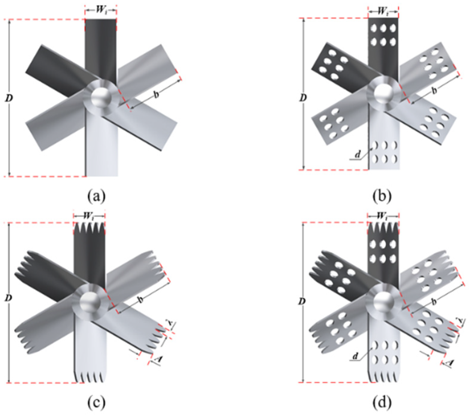
Based on the potential benefits of perforation and bionics, three novel impellers with different structures were proposed in this paper by introducing apertures and bionic cuts into the traditional impeller (PBT), the geometric dimensions of the conventional impeller (PBT) and the novel impellers (PBPT, BCBT, and BCPBT) are shown in Figure 2. PBT is commonly used in the solid–liquid mixing processes of industrial applications. PBPT adds holes to the blade surfaces of the PBT. Inspired by bionic design, BCBT has bionic cuts on the edge of the PBT. The contour of the bionic cuts is a sine function curve, and its shape is determined by the wavelength and amplitude. BCPBT combines the holes and bionic cuts. Compared with the traditional impeller optimization design, BCPBT has the advantages of promoting turbulence uniformity and enhancing mixing because of holes and bionic cuts. These impeller structures are determined by impeller diameter, D, blade width, Wi, blade length, b, aperture diameter, d, aperture ratio, β, wavelength, λ, amplitude, A and other structural parameters. The basic dimensions of the impeller are summarized in Table 1. The change of each structural parameter may have a significant impact on mixing efficiency.

3. PIV Experimental Apparatus

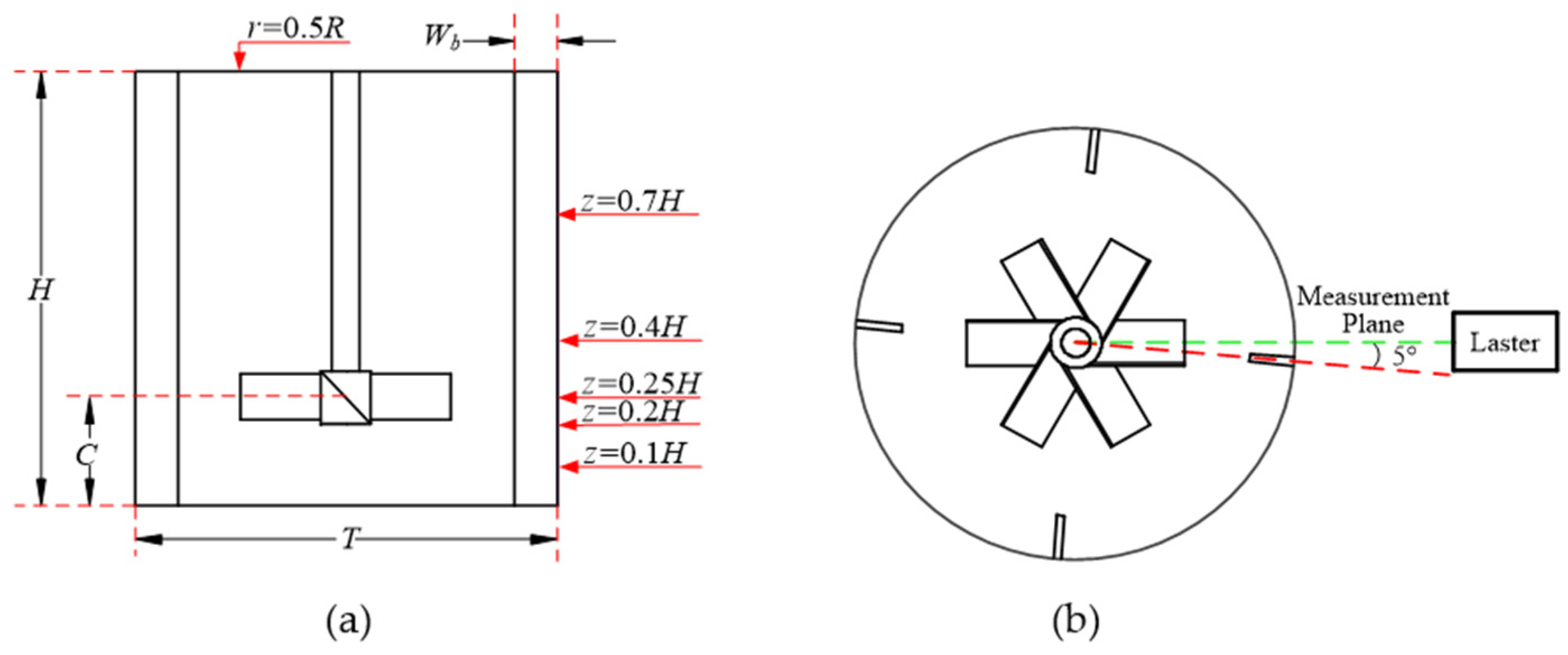
The two-dimensional (2D) PIV system (Microvec Pte Ltd, Beijing, China) adopted in the present work consisted of a dual Vlite series 532 nm dual pulse laser (Beamtech Optronics Co., Ltd., 500 mJ, 10 Hz, Beijing, China), a high-resolution CCD camera with 6600 × 4400 pixels, a synchronizer, and the commercial software MicroVec-V3.6. The experimental setup is shown in Figure 3. An electromagnetic phase-locking device was used to obtain the phase-resolved measurements. The signals triggered by the shaft once per revolution were used to synchronize the blade angular position, image acquisition, and laser firing. In all of the experiments, the vertical laser plane was placed at a 5° angle from the nearest baffle, passing through the vessel axis to give a clear and undistorted image of fluid flow [29]. Only half of the plane was measured due to symmetry.
The tracer particles used in this experiment were hollow glass particles with a diameter of 10 to 20 μm and a density of 1030 kg·m−3, which was quite close to the liquid density, so as to better track the liquid velocity. The selected interrogation area was 64 × 64 pixels, and the overlap area was 50% during the correlation. Considering the accuracy of the experimental data and the efficiency of the image processing, 500 pairs of collected images were processed to obtain the time-average flow field in each condition.
A flat-bottomed cylindrical tank equipped with four baffles that were mounted perpendicular to the tank wall was studied, as shown in Figure 4. The dimensions of the tank are listed in Table 1. The cylindrical tank was placed in a square tank to reduce the optical refractive index effect at the cylindrical surface of the tank. In order to prevent the reflection of the laser from damaging the high-speed camera CCD, the impellers and shaft were painted black. The tank was stirred by the traditional impeller (PBT) and the novel impellers (PBPT, BCBT and BCPBT), as depicted in Figure 2. The properties of the liquid and the solid particles are given in Table 2.

4. Mathematical Model

The Eulerian–Eulerian (E-E) approach was applied to analyze the hydrodynamic behaviors of multiphase systems in various stirred vessels because of its lower CPU time cost compared with the Eulerian–Lagrangian (E-L) approach [30,31]. The fatal problem is that it only considered the drag force between the solid particles and fluid with less attention paid to the interaction between solid particles. For this reason, Gidaspow [32] proposed the kinetic theory of granular flow (KTGF). Wadnerkar et al. [33] and Xie et al. [34] investigated solid–liquid mixing systems utilizing E–E and Eulerian–Eulerian methods combined with the kinetic theory of granular flow (EE-KTGF), and found that the EE-KTGF method is available to accurately predict the flow field and particle distribution with high concentrations and large particle sizes. Therefore, the EE-KTGF model was adopted to describe the solid–liquid two-phase flow in the stirred tank in the present work. This model assumed that the solid was a pseudo fluid. Viscosity, solid pressure and stress were solved by the KTGF model. The continuity equation and momentum equation of each phase were solved under the Euler framework, and the coupling between phases was obtained through the pressure and interphase exchange coefficients.

4.1. Governing Equations

Each phase was regarded as an interpenetrating continuum. Reynolds-averaged mass and momentum balance equations were solved for each phase. The governing equations for phase q are as follows [32]:
Continuity equation:
t ( α i ρ i ) + · ( α i ρ i u i ) = 0
where α i , is the concentration of each phase, and ρ and u i are the density and velocity vector, respectively.
Momentum equation:
The momentum equation for the liquid phase is:
t ( α l ρ l u l ) + · ( α l ρ l u l u l ) = α l p + α l · τ = l + α l ρ l g K ( u l u s )
where p is the thermodynamic pressure, K the momentum transfer coefficient, g the gravity acceleration, and τ = l the viscous stress tensor of liquid phase listed in Table 3.
The momentum equation for the solid phase is:
t ( α s ρ s u s ) + · ( α s ρ s u s u s ) = α s p p s + · τ = s + α s ρ s g + K ( u l u s )
where τ = s is the viscous stress tensor of solid phase and p s is the solid pressure shown in Table 3.
The effects of mass transfer, lift force and virtual mass force were ignored. Only the drag force, which significantly influences the simulation results, was considered in this paper [34]. The Huilin–Gidaspow model [35] was adopted to calculate the momentum exchange coefficient:
K = ( 1 ψ ) K E + ψ K W Y
ψ = arctan [ 150 × 1.75 ( 0.2 α s ) ] π + 0.5
K E = 150 ( 1 α l ) 2 μ l ( α l d s ) 2 + 1.75 ρ l ( 1 α l ) | u l u s | α l d s α l 0.8
K W Y = 3 4 C D ρ l ( 1 α l ) | u l u s | d s α l 2.65 α l > 0.8
C D = 24 α l R e s [ 1 + 0.15 ( α l R e s ) 0.687 ]
R e s = ρ l d s | u s u l | μ l
where K is fluid-solid exchange coefficient, ψ is the stitching function, CD is the drag function, and Res is the relative Reynolds number.
Montante [36] found that the mixture model is the most proper turbulence model. For this reason, both the turbulent kinetic energy and dissipation rate of the liquid phase were calculated using the mixture k-ε turbulence model where the two phases are assumed to share the same k and ε. The k and ε equations describing this model are as follows:
t ( ρ m k ) + · ( ρ m u m k ) = · ( μ m + μ t , m σ k k ) + G k , m + G b , m ρ m ε
t ( ρ m ε ) + · ( ρ m u m ε ) = · ( μ t , m σ ε ε ) + ε k ( C 1 ε G k , m C 2 ε ρ m ε )
where the mixture density, ρm, molecular viscosity, μm and velocity, u m , are computed from
ρ m = i = 1 N α i ρ i
μ m = i = 1 N α i μ i
u m i = 1 N α i ρ i u i i = 1 N α i ρ i
The turbulent viscosity for the mixture, μ t , m , is computed from
μ t , m = ρ m C μ k 2 ε
and the production of turbulence kinetic energy, Gk,m, is computed from
G k , m = μ t , m ( u m + u m T ) : u m
The constants involved in the above equations are C 1 ε = 1.44 , C 2 ε = 1.92 , C μ = 0.09 , σ k = 1.0 , σ ε = 1.3 , respectively.
The equation of the conservation of granular temperature can be expressed as:
3 2 [ t ( α s ρ s θ s ) + · ( α s ρ s u s θ s ) ] = ( p s I = + · τ = s ) : u s + · ( k θ s θ s ) γ θ s + φ l s
where θ s is the granular temperature for the solid phase, ( p s I = + · τ = s ) : u s is the generation of energy by the solid stress tensor, · ( k θ s θ s ) is the diffusion of energy, k θ s is the diffusion coefficient for granular energy, γ θ s is the collisional dissipation of energy and φ l s is the energy exchange between the liquid phase and the solid phase, as given in Table 3.

4.2. Numerical Details

Based on the complex geometry, the computational domain was discretized by unstructured grids. The commercial CFD solver FLUENT was utilized to solve the governing equations of the solid and liquid phases in a double precision solver. The Eulerian model was selected as the multiphase model to describe the liquid–solid flow. The transient pressure-based solver with implicit formulation was specified, and the absolute velocity formulation was adopted. The segregated SIMPLEC algorithm was adopted to couple pressure and velocity. The convection term was discretized with a second order upwind scheme, and central differences were employed for all diffusion terms.
A sliding grid (SG) algorithm was applied to simulate the impeller rotation with a set time step of 0.001 s. As far as the SG simulations are concerned, 100 full revolutions were considered sufficient to reach steady state conditions in all cases [37]. The standard wall function was applied for the modeling of the near-wall zones. All geometry walls were assumed to be no slip boundary conditions, except that the top surface adopted the free slip condition to simulate a free surface. Under the initial conditions, the solid particles were settled uniformly at the bottom of the tank, while the liquid was kept stationary in the remaining space of the tank.

4.3. Validation against PIV Experiment

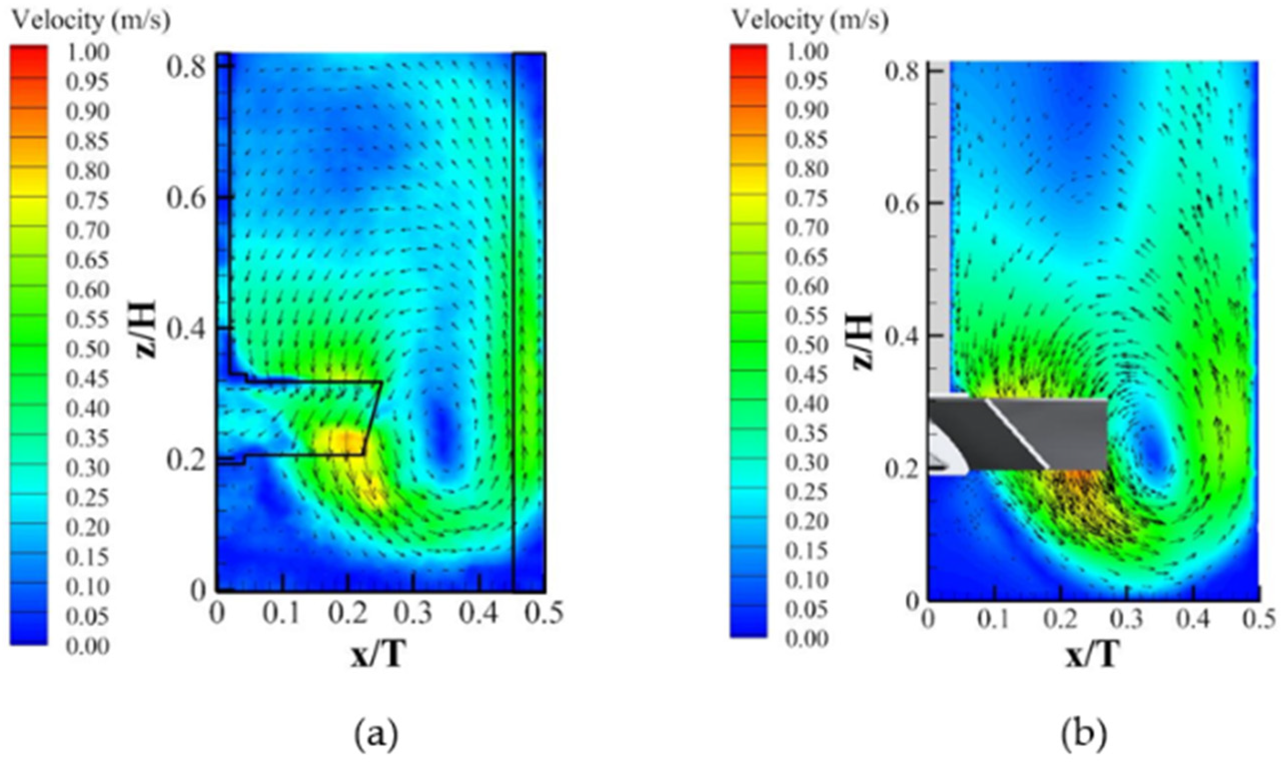
The reliability of the simulation was verified by the self-conducted PIV experiment. The system becomes opaque at higher volume fractions and impeller speeds, which affects the application of optical measurement techniques. Thus, the impeller speed was set at 240 rpm and the solid volume fraction was 2%. The simulation and experiment were carried out under the same conditions. Figure 5 compares the liquid phase flow field of the PIV experiment and CFD simulation. A large single circulation loop existed in the stirred tank. The liquid was ejected obliquely downward from the impeller to the bottom of the tank with a maximum velocity magnitude and then divided into two streams. Most of the liquid was fed into the main circulation of the whole tank, which forms the downward main loop; and a small part went down, forming the inverted conical secondary induced circulation region in the center of the bottom of the tank. A high-speed flow was generated near the tip of the blade due to the rotation of the impeller, and the downward flow formed a high-speed jet. The liquid velocity was relatively high in the impeller region and along the jet, whereas it was lower at the upper part of the stirred tank and at the center of the bottom of the tank. The simulation and experimental results are consistent, which verifies the reliability of the EE-KTGF model.

4.4. Verification for Grid Independence

After the qualitative verification of the EE-KTGF model, the simulation results for the axial, radial and tangential velocities at z = 0.2H obtained using computational grids with 700, 1300 and 1800 k cells were compared with the experimental data from Guida et al. [25] to ensure grid independency and reliable results in high solid loading systems. The impeller speed was 405 rpm and the solid volume fraction was 5.2%. Figure 6 and Figure 7 display three velocity components of both the liquid and solids with different mesh cells. The velocity components were normalized by the impeller tip speed, utip. It is evident that the results with different cells have the same variation trend, but the 700 k cells had a large deviation compared with experimental data. A further-refined mesh was required to acquire accurate results. The normalized velocity components obtained using numerical simulation with 1300 k cells and 1800 k cells were in good agreement with the experimental results. The average relative error between the CFD and the experimental results was 9.7%, indicating that the simulation method can reasonably predict complex flow in the stirred tank. The relative error for the normalized velocity component between 1300 k cells and 1800 k cells was less than 5%. Therefore, the mesh with 1300 k cells was used for the subsequent simulations to achieve a compromise between accuracy and computational cost.

5. Results and Discussions

5.1. Flow Filed

The flow field of the different impeller types (PBT, PBPT, BCBT and BCPBT) in the stirred tank is shown in Figure 8. It is illustrated that all impellers are able to generate axial flow. The aperture and gaps will not cause the change of the typical flow pattern. However, the flow field can be influenced crucially by means of modifications in the impeller blade shape. It is interesting to note that the velocity vector is quite different in the impeller region. The velocities of PBPT, BCBT and BCPBT were obviously higher than that of PBT and the axial circulations were strengthened, which is attributed to the effect of the jet. Many high-speed jets were generated behind the blade when the liquid flowed through the apertures and gaps around the impeller. The shear effect of the jet on the surrounding liquid led to remarkable growth in the velocity gradient, thereby improving the flow capacity of the impellers.

5.2. Trailing Vortices

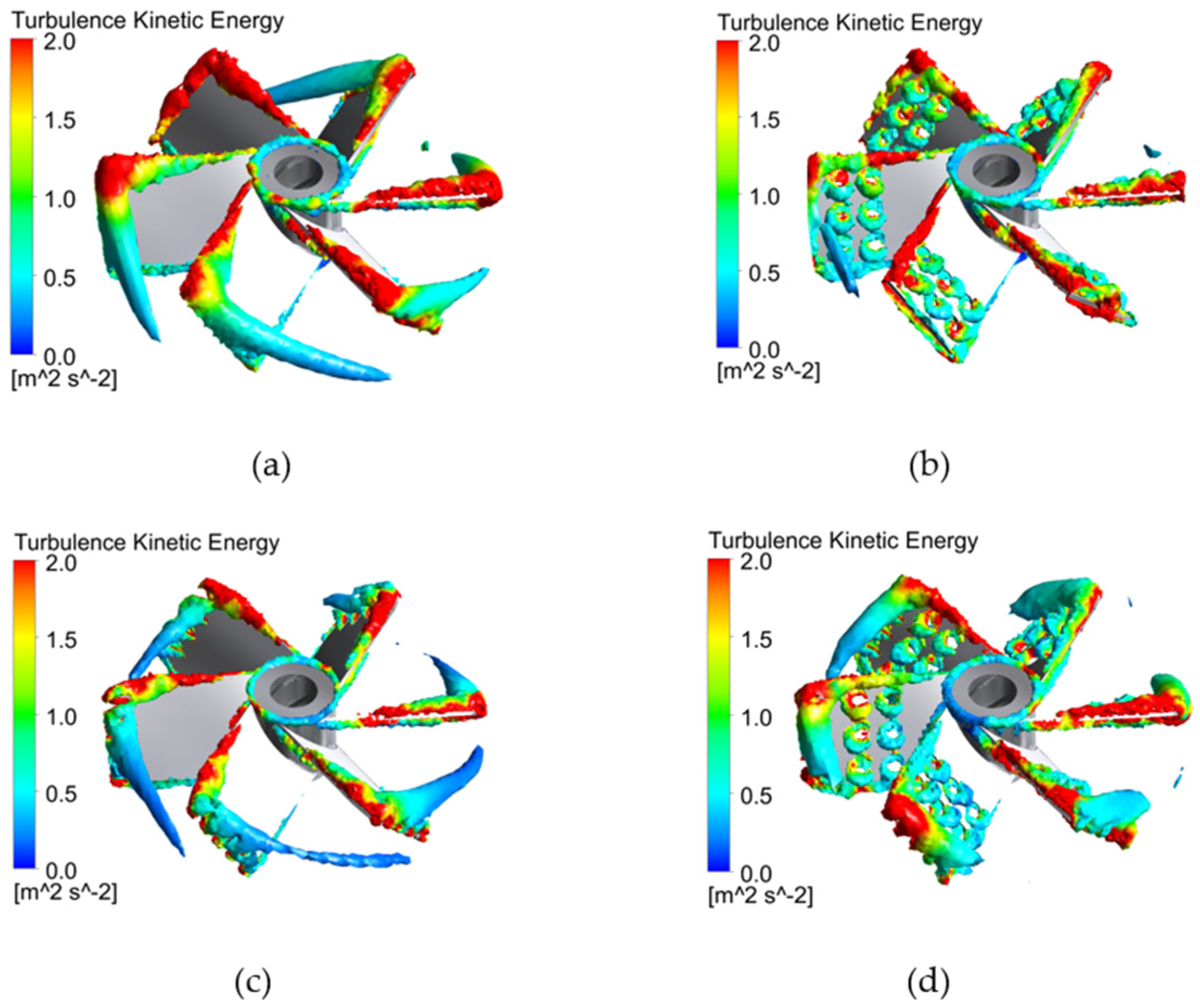
It is critical to study the characteristics of trailing vortices. Figure 9 presents the three-dimensional structure of the trailing vortices behind the different impeller blades. The trailing vortices were produced behind each blade. A large part of the impeller energy was consumed in the trailing vortices, while only a tiny part of the energy could be transferred to the far end of the flow field for the suspension process of solid particles. Comparing with Figure 9a–d, the trailing vortices near the PBT were characterized by large size, narrow shape and small influence range, which are not beneficial features for energy transfer. Nevertheless, the novel impellers were able to significantly change the trailing vortex structures. The large trailing vortices observed in the wake of the PBT blades were replaced with multiple, weaker vortices in the wake of the novel impellers. It can be proved that the novel impellers could effectively reduce the size of the trailing vortex through the apertures and gaps around the impeller blades, which are conducive to improving energy utilization and enhancing mixing efficiency. Many small-scale vortices were formed at the apertures and gaps of the novel impellers. The turbulent kinetic energy around the vortices was more prominent, which was in favor of improving stirring efficiency. In addition, the pressure at the center of these vortices was relatively low, giving the impeller some extra driving force and reducing energy consumption to a certain extent.

5.3. Pressure Filled

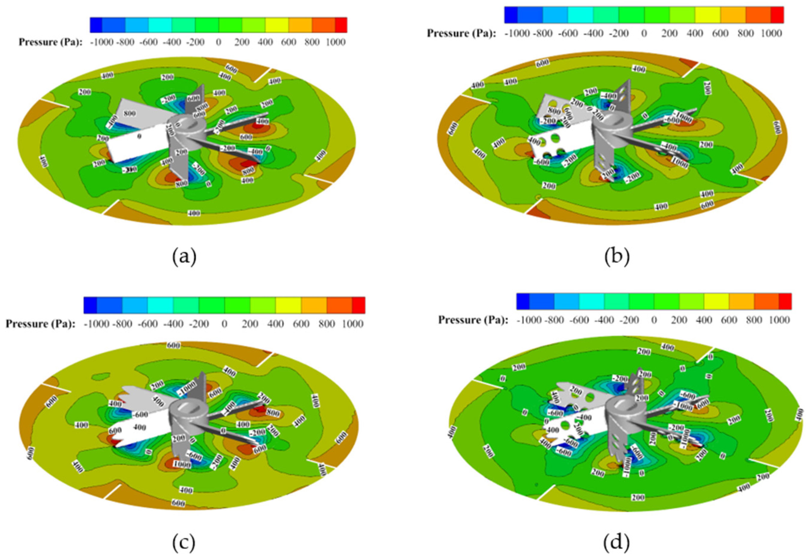
The pressure difference is the main driving force directly affecting power consumption. Figure 10 compares the contour plots of pressure on the center plane of the impeller (z = 0.25H). It can be found that the distribution of pressure on the pressure sides is the largest, but that negative pressure appears on the suction sides. The input of energy is required to overcome the pressure difference and achieve material mixing when the impeller rotates. Compared with the PBT, the novel impellers are capable of reducing the pressure difference and alleviating the obstruction of the pressure difference. The possible reason is that a series of jets can be generated around the apertures and gaps, thus producing an enormous number of smaller vortices, which also reduce the pressure difference ahead and behind the impeller blade and improve energy transfer efficiency. BCPBT had the most obvious effect of reducing the pressure difference.

5.4. Solid Particle Distribution

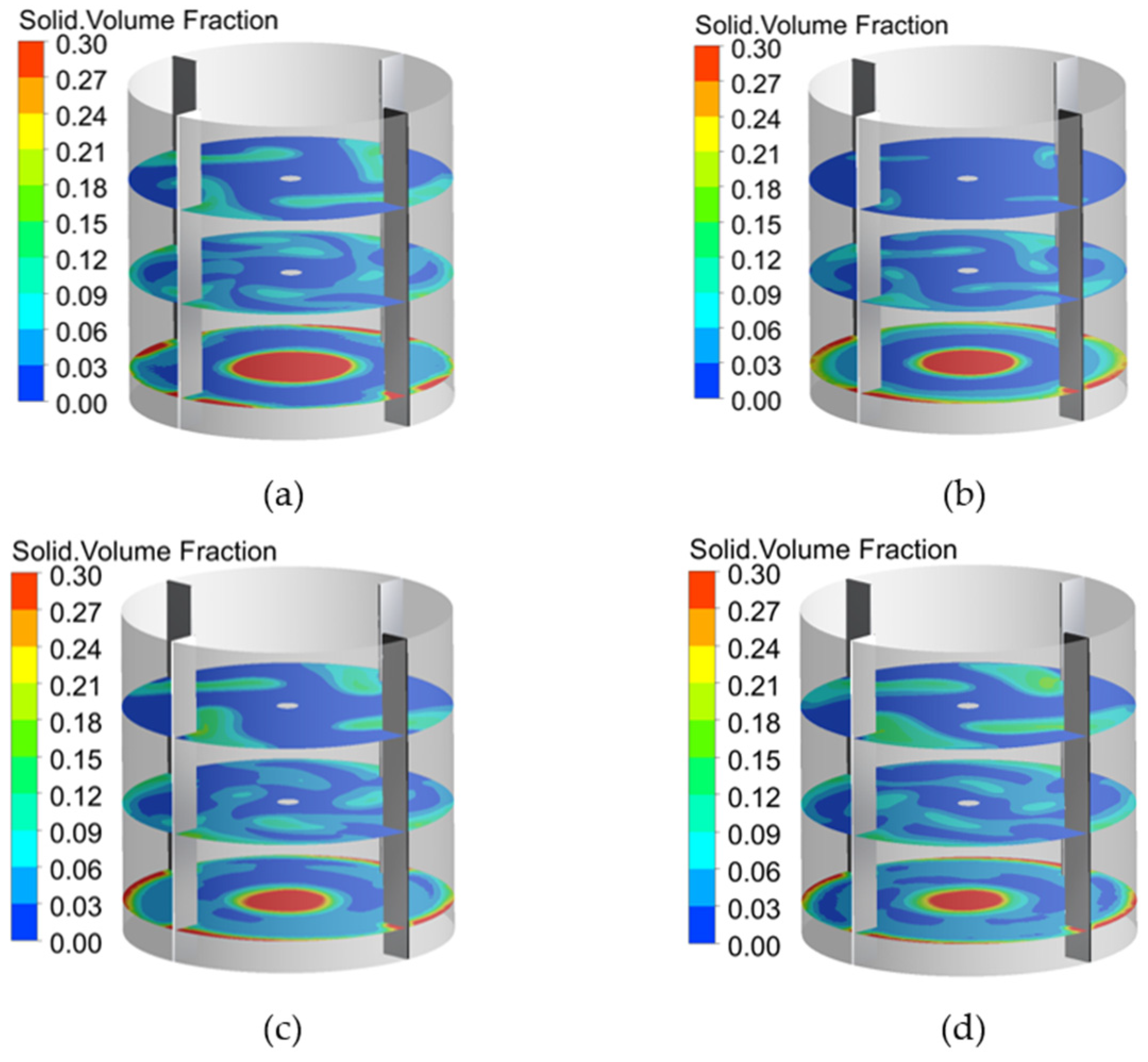
The proper quantification of solid dispersion is indispensable for a detailed understanding of the hydrodynamics of solid–liquid stirred tanks, as it strongly impacts the mass transfer between the liquid and the particles. Figure 11 reports the solid volume fraction of vertical cross-section (z = 0.1H, z = 0.4H, z = 0.7H), and Figure 12 shows the axial distribution of the solid volume fraction at R/r = 0.5. As depicted in Figure 11, there was particle accumulation under the impeller and around the baffle. The novel impellers, however, may function to reduce the deposition of solid particles at the bottom of the stirred tank and the thickness of the clear liquid layer at surface was lower than that of the PBT. The PBPT, BCBT and BCPBT improved the solid suspension quality in the stirred tank compared with the PBT. The dispersion degree of solid particles in the PBPT and BCBT impeller systems were superior to that of the PBT impeller system under the same operation condition, and the BCPBT could further promote the dispersion degree of solid particles on the basis of PBPT and BCBT. This phenomenon can also be observed in Figure 12. Obviously, a conclusion could be drawn that the capacity of BCPBT for solid suspension is superior to that of other impellers. As previously mentioned, it might be explained by the fact that the apertures and gaps around the novel impellers causes a series of high-speed jets generation around the blade, and that the shear effect of the jets on the surrounding liquid generated many stable small-scale vortices, thus advancing the local energy dissipation rate around the liquid and enhancing the mixing effect.

5.5. Power Consumption

Power input is a major cost in industrial-scale stirred tanks. In the present work, the power consumption of different impeller types was calculated by the torque monitor applied to the impeller walls. The power input was mainly used to overcome the pressure gradient. A reduction of the pressure difference drag force and projected area on the novel impellers were the dominant factors explaining the lower power consumption. Furthermore, many small-scale vortices were formed around the apertures and gaps of the novel impeller. The pressure in the center of these vortices was relatively low, which gives some extra driving force to the impeller and can also reduce the energy consumption to a certain extent. The variations of the power consumption of different impellers at the same speed re tabulated in Table 4, which shows that the novel impellers can reduce power consumption to varying degrees. The sequence of decreasing power consumption at the same impeller speed is: PBT > PBPT > BCBT > BCPBT. Of note was the sharp power consumption drop of 17% when the BCPBT was employed instead of the PBT.

5.6. Influence of Aperture Parameters

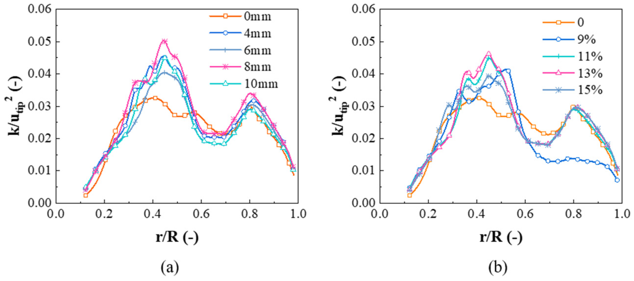
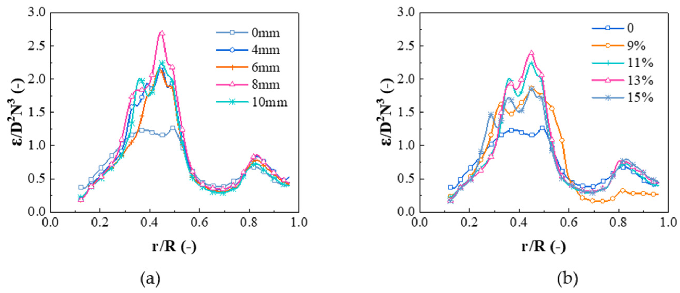
It is known that turbulence kinetic energy and turbulent energy dissipation rate play scrucial role in the mixing time and solid–liquid suspension quality. Figure 13 and Figure 14 depict the distributions of the turbulence kinetic energy and the turbulent energy dissipation rate at different aperture diameters and aperture ratios, respectively. In all cases, the turbulenve kinetic energy and turbulent energy dissipation rate were highest near the impeller blade tip, but tended to be very low outside the sweep field by the impeller blades. The turbulence kinetic energy and turbulent energy dissipation rate profiles of the BCPBT presented increased values than those of the PBT for most of the positions and show multiple spikes, especially near the impeller (from r/R = 0.3 to r/R = 0.6). The turbulent energy dissipation rate was higher for the BCPBT, which implies that smaller trailing vortices in the wake of the BCPBT blade dissipated over a shorter distance from the impeller.
The turbulence kinetic energy and turbulent energy dissipation rate have an increasing trend with an increase in the aperture diameter; however, they decreased slightly when the aperture diameter was too large. Overall, the aperture diameter should not be too large, and 8 mm is more suitable. As shown in Figure 13b and Figure 14b, the turbulence kinetic energy and turbulent energy dissipation rate increased with the increase of the aperture ratio. Under conditions of an aperture ratio of 13%, the turbulence kinetic energy and turbulent energy dissipation rate were the largest, showing a downward trend when the aperture ratio as more than 13%. The vortex diffusion as weak due to the small aperture ratio. In the case of an oversized aperture ratio, the concurrent flow can emerge easily, thereby affecting the enhancement of eddy diffusion.
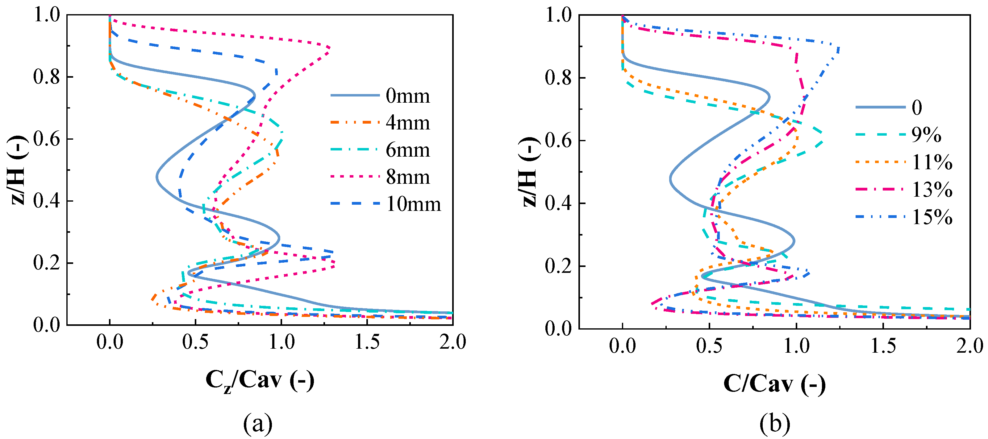
Figure 15 depicts the axial solid concentration profile for different aperture parameters at r/R = 0.5. With the increase of aperture diameter, mixing effects were improved in the axial direction. When the aperture diameter reaches 8 mm, a better mixing performance forms in the tank, where particle deposition decreases significantly at the bottom. As the aperture diameter increases to 10 mm, owing to the fact that the axial pumping effects of impellers are weakened in the vertical direction, it has an adverse impact on particle axial motion. As a result, the solid hold-up is larger, and the deposition is more severe at the bottom of tank. It can be observed from Figure 15b that the Cz/Cav values of the BCPBT were higher than those of the PBT. The distribution of the solid particles of BCPBT was more uniform than that of PBT in the axial direction when the aperture ratio was 13%.
An interface appears between the suspended solids and a clear liquid layer in the upper part of the tank. The height of this interface is the cloud height. In this research, the cloud height was analyzed by means of monitoring the average solid concentration iso-surface, which was defined as the maximum axial height of the iso-surface of the average solid concentration. The cloud height can be taken as a significant parameter for evaluating mixing degree. Figure 16 exhibits the change of cloud height in the stirred tank. Owing to the jet effect of the BCPBT, solid particles could be pumped to a higher position, which improved the lifting ability of the liquid to the solid particles. Consequently, the cloud height in the stirred tank with the BCPBT was higher than that with the PBT. Cloud height trends higher with an increase in aperture size, reaches a maximum value, and then drops gradually with further increases in the aperture size. The orifice flow velocity shows a dampening with the increase of the aperture size. If the aperture size is too small, the local eddy diffusion intensity is not enough. However, a slight velocity gradient is formed in the flow field when the aperture size is too large, thereby causing the shear stress of the impeller to weaken. The cloud height was the largest at the aperture ratio of 13%. With further increases of the aperture ratio, the cloud height slightly declined. An increase in the aperture ratio increased the number of apertures on the blade, and the jet flows were converted to concurrent flows, leading to a negative impact on the mixing process. However, the aperture ratio was too small to produce enough vortices for energy diffusion. From the above we can conclude that better solid–liquid suspension quality can be acquired when the aperture diameter is equal to 8 mm and the aperture ratio is equal to 13%.

5.7. Influence of Liquid Viscosity

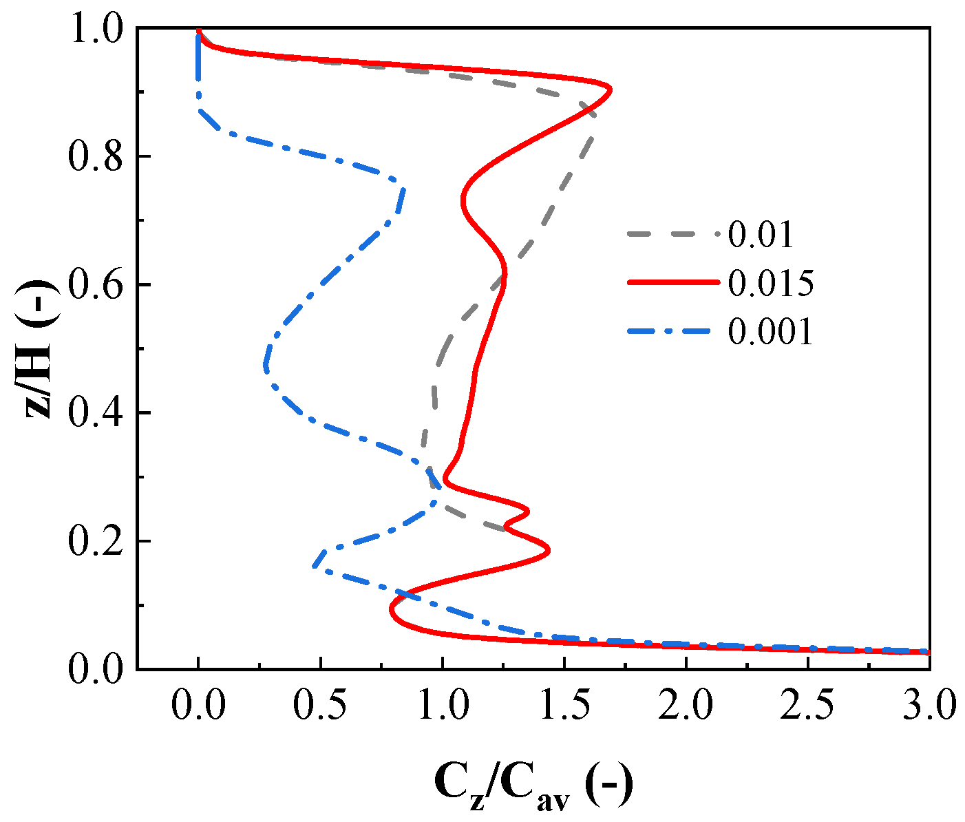
Figure 17 illustrates the axial solid concentration profile at r = 0.5R as a function of liquid viscosity for the BCPBT. It can be seen that the BCPBT can effectively enhance the solid–liquid mixing degree under different liquid viscosities, which shows that it can be applied to various industrial productions, such as the preparation of PCMs. With an increase in the liquid viscosity, the Cz/Cav value prominently increases and lower solid concentration gradients in the axial direction are observed. The more viscous the liquid, the more easily the solid particles remain suspended, and the more uniform the particle distribution. The reason is that the higher viscous drag leads to the smaller settling velocity of a single particle, thus preventing the solid particles from returning to the bottom of the tank after suspension.

5.8. Influence of Impeller Speed

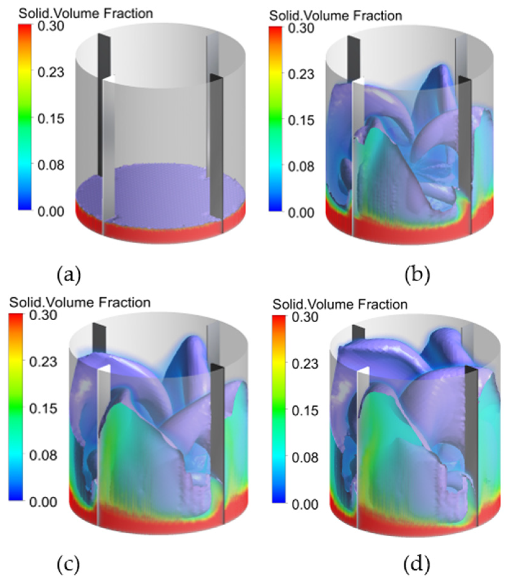
Figure 18 suggests the three-dimensional view of solid volume fraction iso-volume and the solid volume fraction of vertical cross-section for different impeller speeds. Figure 19 exhibits the 3D solid volume fraction contour plots and cloud height. At a low impeller speed (i.e., 180 rpm), solid particles are basically deposited at the bottom of the tank, and the upper parts of the stirred tank are almost liquid. An increase in impeller speed decreases the accumulation region at the bottom of the stirred tank gradually. More and more particles are suspended and dispersed in the stirred tank, and the distribution of the solid particles is uniform. Only a few solid particles accumulate below the impeller and around the baffles at impeller speeds of 540 rpm, and more solid particles are pumped to a higher position. As can be seen from Figure 19, the cloud height gradually increases with an increase in impeller speed. According to Zwietering’s criterion [38], the state of complete suspension is defined as no solid remains stationary on the vessel base for more than 1–2 s. Kraume [39] indicates that the cloud height reaching 90% or more of the liquid height can be considered to have reached the state of complete suspension. When the impeller speed reaches 420 rpm, the cloud height has reached 90% of the liquid height, which can be considered the state of complete suspension. There is no significant increment in cloud height with a further increase in the impeller speed.

6. Conclusions

In order to improve the performance and production efficiency of PCMS at an industrial scale, three novel impellers (PBPT, BCBT and BCPBT) were proposed in this paper. The performance of the original impeller (PBT) and three novel impellers were evaluated in a solid–liquid stirred tank utilizing the EE-KTGF approach. The numerical model was verified by a PIV experiment and the experimental data from Guida et al. [25]. The flow field, trailing vortex, turbulent parameters, local axial solid concentration profile and cloud height were predicted. Furthermore, the effects of aperture parameters, impeller speed and liquid viscosity of BCPBT on solid–liquid mixing homogeneity were studied. The results of the current study can be summarized as follows:
The novel impellers are able to generate high-speed jets in the process of rotation, which can not only reduce the size of the trailing vortex and the pressure difference of the impeller blade, but also enhance the velocity gradient and turbulence parameters in this manner to improve the solid–liquid suspension quality and reduce power consumption. Notably, the BCPBT can more effectively suspend solid particles, and the power consumption shows a decrease of approximately 17%, which is of great significance for the preparation processes of PCMs in refrigeration systems.
Proper impeller structure parameters play an essential role in the solid–liquid mixing performance of a stirred tank. An aperture diameter of 8 mm and the aperture ratio of 13% are especially appropriate for the solid–liquid suspension process in this work. An appropriate selection of other design and structure parameters, such as the amplitude and wavelength of the bionic cut, impeller clearance and diameter will be addressed in the near future.
The BCPBT facilitated the solid–liquid suspension for different viscosities of liquids, and increasing the impeller speed in a certain range can significantly promote the solid–liquid mixing. Moreover, the approach of opening holes and bionic cuts is also applicable to other types of impellers. The punched-bionic impeller, therefore, can be widely utilized for many chemical industry and energy applications, such as in the preparation processes of PCMs for solid–liquid mixing.

Author Contributions

Data curation, Z.G.; funding acquisition, S.Z.; investigation, D.X. and Q.Y.; project administration, S.Z.; methodology, W.Z.; validation, D.X. and Q.Y.; writing—original draft, W.Z.; writing—review and editing, Z.G. All authors have read and agreed to the published version of the manuscript.

Funding

The author(s) disclosed receipt of the following financial support for the research, authorship, and/or publication of this article: this work is supported by National Natural Science Foundation of China (Grant No. 51706203), the National Science and technology major special sub project (2019zx06004001) and the Natural Science Foundation of Zhejiang Province, exploration project (Y, LY20E090004).

Acknowledgments

Thanks to Zhejiang University of Technology for providing computing resources and technical support. The authors also appreciate all other scholars for their advice and assistance in improving this article.

Conflicts of Interest

The author(s) declared no potential conflicts of interest with respect to the research, authorship, and/or publication of this article.

Nomenclature

AAmplitude, mm
bBlade length, mm
COff-bottom clearance, mm
CavAverage concentration
CzAxial concentration
C1ε, C2ε, CμCoefficients of turbulent model
DImpeller diameter, mm
dsSolid particle diameter, mm
daperture diameter, mm
Gk,mTurbulence generation, kg·m/s3
gGravity acceleration, m/s2
HLiquid height, mm
HCCloud height
ii = 1 for liquid phase or 2 for solid phase
KInterface momentum transfer coefficient
kTurbulent kinetic energy, m2/s2
Nimpeller speed, rpm
pPressure, pa
ReReynolds number
TTank diameter, mm
tTime, s
u Velocity vector
ur, uθ, uzcylindrical velocity components
utipimpeller tip velocity, m/s
WbBaffle width, mm
WiBlade width, mm
x,y,zCartesian coordinates
Greek Letters
αVolume fraction
βaperture ratio, %
λWavelength, mm
εTurbulent kinetic energy dissipation rate, m2/s3
μshear viscosity, Pa s
ρDensity, kg/m3
σPrandtl number
τ = Viscous stress tensor, Pa
υbulk viscosity, Pa
Subscripts
lLiquid phase
sSolid phase
mMixture properties

References

  1. Xu, Y.; Huang, Y.; Jiang, N.; Song, M.; Xie, X.; Xu, X. Experimental and theoretical study on an air-source heat pump water heater for northern China in cold winter: Effects of environment temperature and switch of operating modes. Energy Build. 2019, 191, 164–173. [Google Scholar] [CrossRef]
  2. Xu, Y.; Mao, C.; Huang, Y.; Shen, X.; Xu, X.; Chen, G. Performance evaluation and multi-objective optimization of a low-temperature CO2 heat pump water heater based on artificial neural network and new economic analysis. Energy 2021, 216, 119232. [Google Scholar] [CrossRef]
  3. Ürge-Vorsatz, D.; Cabeza, L.F.; Serrano, S.; Barreneche, C.; Petrichenko, K. Heating and cooling energy trends and drivers in buildings. Renew. Sustain. Energy Rev. 2015, 41, 85–98. [Google Scholar] [CrossRef] [Green Version]
  4. Nie, B.; Palacios, A.; Zou, B.; Liu, J.; Zhang, T.; Li, Y. Review on phase change materials for cold thermal energy storage applications. Renew. Sustain. Energy Rev. 2020, 134, 110340. [Google Scholar] [CrossRef]
  5. Nagano, K.; Takeda, S.; Mochida, T.; Shimakura, K.; Nakamura, T. Study of a floor supply air conditioning system using granular phase change material to augment building mass thermal storage—Heat response in small scale experiments. Energy Build. 2006, 38, 436–446. [Google Scholar] [CrossRef]
  6. Konuklu, Y.; Ostry, M.; Paksoy, H.O.; Charvat, P. Review on using microencapsulated phase change materials (PCM) in building applications. Energy Build. 2015, 106, 134–155. [Google Scholar] [CrossRef]
  7. Jafari, R.; Tanguy, P.A.; Chaouki, J. Characterization of Minimum Impeller Speed for Suspension of Solids in Liquid at High Solid Concentration, Using Gamma-Ray Densitometry. Int. J. Chem. Eng. 2012, 2012, 945314. [Google Scholar] [CrossRef]
  8. Ayranci, I.; Kresta, S. Design rules for suspending concentrated mixtures of solids in stirred tanks. Chem. Eng. Res. Des. 2011, 89, 1961–1971. [Google Scholar] [CrossRef]
  9. Paul, E.L.; Atiemo-Obeng, V.A.; Kresta, S.M. Handbook of Industrial Mixing: Science and Practice; John Wiley & Sons: New York, NY, USA, 2004. [Google Scholar]
  10. Jaworski, Z.; Dyster, K.; Nienow, A. The Effect of Size, Location and Pumping Direction of Pitched Blade Turbine Impellers on Flow Patterns: LDA Measurements and CFD Predictions. Chem. Eng. Res. Des. 2001, 79, 887–894. [Google Scholar] [CrossRef]
  11. Schäfer, M.; Yianneskis, M.; Wächter, P.; Durst, F. Trailing vortices around a 45° pitched-blade impeller. AIChE J. 1998, 44, 1233–1246. [Google Scholar] [CrossRef]
  12. Driss, Z.; Bouzgarrou, G.; Chtourou, W.; Kchaou, H.; Abid, M. Computational studies of the pitched blade turbines design effect on the stirred tank flow characteristics. Eur. J. Mech. B/Fluids 2010, 29, 236–245. [Google Scholar] [CrossRef]
  13. Gu, D.; Ye, M.; Wang, X.; Liu, Z. Numerical investigation on mixing characteristics of floating and sinking particles in a stirred tank with fractal impellers. J. Taiwan Inst. Chem. Eng. 2020, 116, 51–61. [Google Scholar] [CrossRef]
  14. Gu, D.; Liu, Z.; Qiu, F.; Li, J.; Tao, C.; Wang, Y. Design of impeller blades for efficient homogeneity of solid-liquid suspension in a stirred tank reactor. Adv. Powder Technol. 2017, 28, 2514–2523. [Google Scholar] [CrossRef]
  15. Vasconcelos, J.M.T.; Orvalho, S.C.P.; Rodrigues, A.M.A.F.; Alves, S. Effect of Blade Shape on the Performance of Six-Bladed Disk Turbine Impellers. Ind. Eng. Chem. Res. 2000, 39, 203–213. [Google Scholar] [CrossRef]
  16. Trivellato, F. On the efficiency of turbulent mixing in rotating stirrers. Chem. Eng. Process. Process. Intensif. 2011, 50, 799–809. [Google Scholar] [CrossRef]
  17. Zhao, J.; Gao, Z.; Bao, Y. Effects of the Blade Shape on the Trailing Vortices in Liquid Flow Generated by Disc Turbines. Chin. J. Chem. Eng. 2011, 19, 232–242. [Google Scholar] [CrossRef]
  18. Yang, J.; Zhang, Q.; Mao, Z.-S.; Yang, C. Enhanced Micromixing of Non-Newtonian Fluids by a Novel Zigzag Punched Impeller. Ind. Eng. Chem. Res. 2019, 58, 6822–6829. [Google Scholar] [CrossRef]
  19. Rao, D.A.; Sivashanmugam, P. Experimental and CFD simulation studies on power consumption in mixing using energy saving turbine agitator. J. Ind. Eng. Chem. 2010, 16, 157–161. [Google Scholar] [CrossRef]
  20. Steiros, K.; Bruce, P.J.K.; Buxton, O.R.H.; Vassilicos, J.C. Power consumption and form drag of regular and fractal-shaped turbines in a stirred tank. AIChE J. 2017, 63, 843–854. [Google Scholar] [CrossRef]
  21. Başbuğ, S.; Papadakis, G.; Vassilicos, J.C. Reduced power consumption in stirred vessels by means of fractal impellers. AIChE J. 2018, 64, 1485–1499. [Google Scholar] [CrossRef]
  22. Fish, F.; Lauder, G. PASSIVE AND ACTIVE FLOW CONTROL BY SWIMMING FISHES AND MAMMALS. Annu. Rev. Fluid Mech. 2006, 38, 193–224. [Google Scholar] [CrossRef] [Green Version]
  23. Lin, Y.-T.; Chiu, P.-H. Influence of leading-edge protuberances of fx63 airfoil for horizontal-axis wind turbine on power performance. Sustain. Energy Technol. Assess. 2020, 38, 100675. [Google Scholar] [CrossRef]
  24. Yan, H.; Su, X.; Zhang, H.; Hang, J.; Zhou, L.; Liu, Z.; Wang, Z. Design approach and hydrodynamic characteristics of a novel bionic airfoil. Ocean Eng. 2020, 216, 108076. [Google Scholar] [CrossRef]
  25. Guida, A.; Nienow, A.W.; Barigou, M. PEPT measurements of solid–liquid flow field and spatial phase distribution in concentrated monodisperse stirred suspensions. Chem. Eng. Sci. 2010, 65, 1905–1914. [Google Scholar] [CrossRef]
  26. Alvarez-Hernández, M.; Shinbrot, T.; Zalc, J.; Muzzio, F. Practical chaotic mixing. Chem. Eng. Sci. 2002, 57, 3749–3753. [Google Scholar] [CrossRef]
  27. Yan, Y.; Avital, E.; Williams, J.; Cui, J. Aerodynamic performance improvements of a vertical axis wind turbine by leading-edge protuberance. J. Wind. Eng. Ind. Aerodyn. 2021, 211, 104535. [Google Scholar] [CrossRef]
  28. Martínez-Delgadillo, S.A.; Alonzo-Garcia, A.; Mendoza-Escamilla, V.X.; González-Neria, I.; Yáñez-Varela, J.A. Analysis of the turbulent flow and trailing vortices induced by new design grooved blade impellers in a baffled tank. Chem. Eng. J. 2019, 358, 225–235. [Google Scholar] [CrossRef]
  29. Gabriele, A.; Nienow, A.; Simmons, M. Use of angle resolved PIV to estimate local specific energy dissipation rates for up- and down-pumping pitched blade agitators in a stirred tank. Chem. Eng. Sci. 2009, 64, 126–143. [Google Scholar] [CrossRef]
  30. Klenov, O.; Noskov, A. Solid dispersion in the slurry reactor with multiple impellers. Chem. Eng. J. 2011, 176-177, 75–82. [Google Scholar] [CrossRef]
  31. Qi, N.; Zhang, H.; Zhang, K.; Xu, G.; Yang, Y. CFD simulation of particle suspension in a stirred tank. Particuology 2013, 11, 317–326. [Google Scholar] [CrossRef]
  32. Gidaspow, D. Multiphase Flow and Fluidization: Continuum and Kinetic Theory Description. J. Non-Newton. Fluid Mech. 1994, 55, 207–208. [Google Scholar]
  33. Wadnerkar, D.; Tade, M.O.; Pareek, V.; Utikar, R.P. CFD simulation of solid–liquid stirred tanks for low to dense solid loading systems. Particuology 2016, 29, 16–33. [Google Scholar] [CrossRef] [Green Version]
  34. Xie, L.; Luo, Z.-H. Modeling and simulation of the influences of particle-particle interactions on dense solid–liquid suspensions in stirred vessels. Chem. Eng. Sci. 2018, 176, 439–453. [Google Scholar] [CrossRef]
  35. Huilin, L.; Yurong, H.; Wentie, L.; Ding, J.; Gidaspow, D.; Bouillard, J. Computer simulations of gas–solid flow in spouted beds using kinetic–frictional stress model of granular flow. Chem. Eng. Sci. 2004, 59, 865–878. [Google Scholar] [CrossRef]
  36. Magelli, F. Modelling of solids distribution in stirred tanks: Analysis of simulation strategies and comparison with experimental data. Int. J. Comput. Fluid Dyn. 2005, 19, 253–262. [Google Scholar] [CrossRef]
  37. Tamburini, A.; Cipollina, A.; Micale, G.; Brucato, A.; Ciofalo, M. CFD simulations of dense solid–liquid suspensions in baffled stirred tanks: Prediction of solid particle distribution. Chem. Eng. J. 2013, 223, 875–890. [Google Scholar] [CrossRef]
  38. Zwietering, T. Suspending of solid particles in liquid by agitators. Chem. Eng. Sci. 1958, 8, 244–253. [Google Scholar] [CrossRef]
  39. Kraume, M. Mixing times in stirred suspensions. Chem. Eng. Technol. 1992, 15, 313–318. [Google Scholar] [CrossRef]
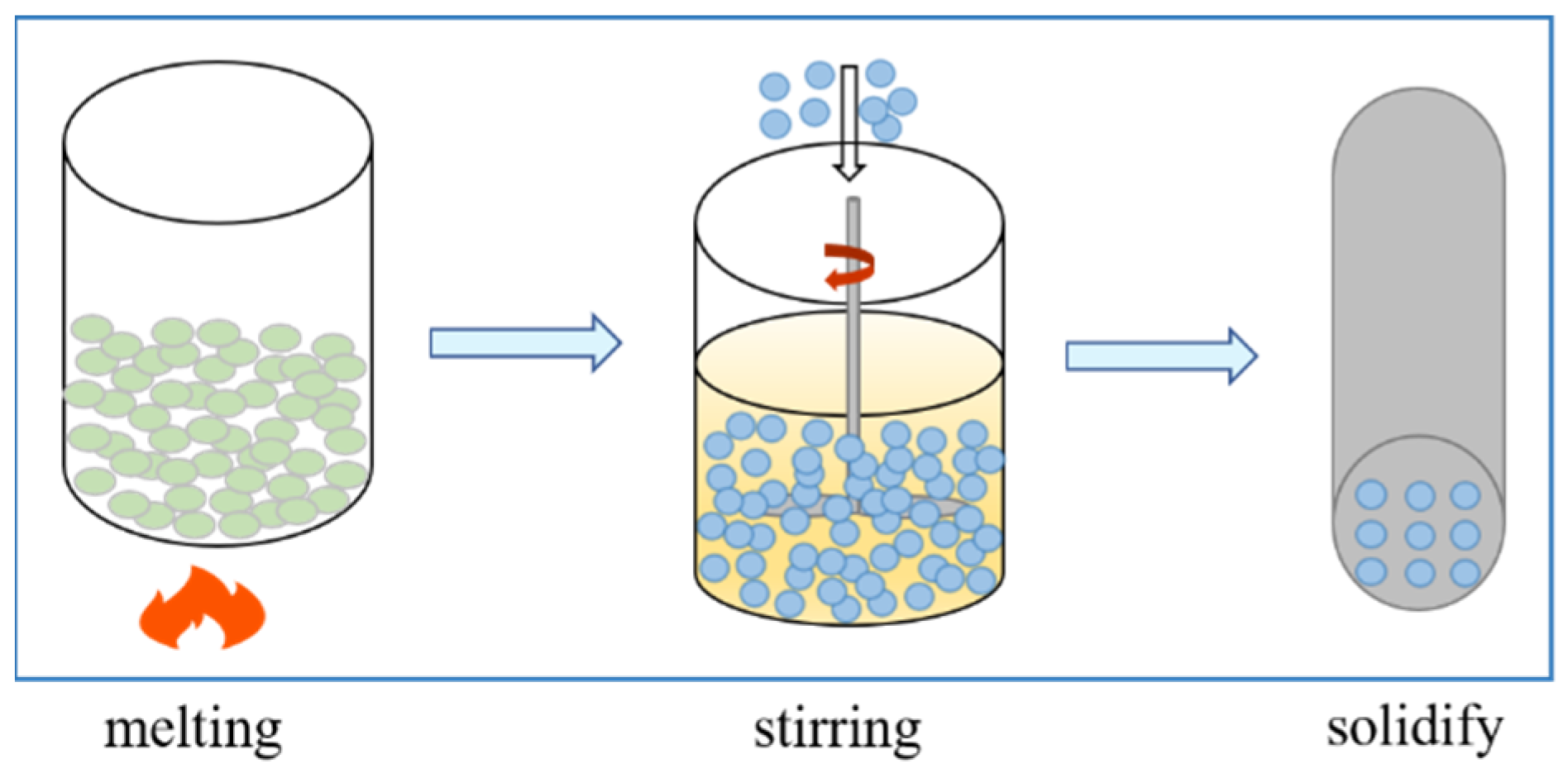
Figure 1. Typical preparation processes of PCMs.
Applsci 11 09883 g001
Figure 2. Structure diagram of the impellers. (a) PBT, (b)PBPT, (c) BCBT, (d) BCPBT.
Applsci 11 09883 g002
Figure 3. PIV measurement system. 1—stirred tank, 2—electromagnetic phase locking device, 3—laser, 4—synchronizer, 5—computer, 6—cylindrical lens, 7—CCD camera.
Applsci 11 09883 g003
Figure 4. Schematic of the investigated stirred tank. (a) Vertical view along the axis and CFD monitoring position, (b) horizontal (top) view and experimental measurement plane.
Applsci 11 09883 g004
Figure 5. Liquid averaged velocity field. (a) PIV experiment, (b) CFD simulation.
Applsci 11 09883 g005
Figure 6. Comparison of radial profiles of liquid velocity with experimental results (z = 0.2H). (a) Axial velocity component uz, (b) radial velocity component ur, (c) tangential velocity component uθ.
Applsci 11 09883 g006
Figure 7. Comparison of radial profiles of solids velocity with experimental results (z = 0.2H). (a) Axial velocity component uz, (b) radial velocity component ur, (c) tangential velocity component uθ.
Applsci 11 09883 g007
Figure 8. Liquid velocity vectors profile around the different impeller blades. (a) PBT, (b) PBPT, (c) BCBT, (d) BCPBT.
Applsci 11 09883 g008
Figure 9. Three-dimensional structure of trailing vortex behind different impeller blades colored by turbulence kinetic energy. (a) PBT, (b) PBPT, (c) BCBT, (d) BCPBT.
Applsci 11 09883 g009
Figure 10. Contour plots of pressure on the center plane of impellers at z = 0.25 H, (a) PBT, (b) PBPT, (c) BCBT, (d) BCPBT.
Applsci 11 09883 g010
Figure 11. Contour plots of the solid volume fraction on horizontal planes at different vessel heights (i.e., z = 0.1H, 0.4H, 0.7H). (a) PBT, (b) PBPT, (c) BCBT, (d) BCPBT.
Applsci 11 09883 g011
Figure 12. Effect of impeller type on local axial solid concentration profile.
Applsci 11 09883 g012
Figure 13. Influence of aperture parameters on local radial turbulence kinetic profiles. (a) Influence of aperture diameter, (b) influence of aperture ratio.
Applsci 11 09883 g013
Figure 14. Influence of aperture parameters on local radial turbulent kinetic energy dissipation rate profiles. (a) Influence of aperture diameter, (b) influence of aperture ratio.
Applsci 11 09883 g014
Figure 15. Influence of aperture parameters on local axial solid concentration profile. (a) Influence of aperture diameter, (b) influence of aperture ratio.
Applsci 11 09883 g015
Figure 16. Influence of aperture parameters on cloud height. (a) Influence of aperture diameter, (b) influence of aperture ratio.
Applsci 11 09883 g016
Figure 17. Effect of liquid viscosity on local axial solid concentration profile.
Applsci 11 09883 g017
Figure 18. 3D sediment volume plot upon contour plots of solid volume fractions on a vertical diametrical plane for different impeller speeds. (a) N = 180 rpm, (b) N = 300 rpm, (c) N = 420 rpm, (d) N = 540 rpm.
Applsci 11 09883 g018
Figure 19. 3D solid volume fraction contour plots and cloud height for different impeller speeds. (a) 180 rpm, (b) 300 rpm, (c) 420 rpm, (d) 540 rpm.
Applsci 11 09883 g019
Table 1. Dimensions of tank and impeller.
ParameterSymbolValue
Tank diameterT288 mm
Liquid heightHT
Baffle widthWb0.1 T
Off-bottom clearanceC0.25 T
Impeller diameterD0.5 T
Blade widthWi41 mm
Blade lengthb55 mm
Table 2. The physical properties of the fluid and particle.
ParameterSymbolValue
Density of the liquid ρ l 1150 kg/m3
Dynamic viscosity of the liquid μ 0.001 pa·s
Density of the solid ρ s 2485 kg/m3
Solid particle diameter d s 3 mm
Solid volume fractionαS5.2%
Table 3. Equations for the KTGF model.
DescriptionEquation
Stress tensor of liquid phase τ = l = α l μ l ( u l + u l T ) + α l ( λ l 2 3 μ l ) u l I =
Stress tensor of solid phase τ = s = α s μ s ( u s + u s T ) + α s ( λ s 2 3 μ s ) u s I =
Solids bulk viscosity λ s = 4 3 α s 2 ρ s d s g 0 , s s ( 1 + e s s ) ( θ s π ) 1 / 2
Solids pressure p s = α s ρ s θ s + 2 ρ s ( 1 + e s s ) α s 2 g 0 , s s θ s
Solids shear viscosity μ s = 4 5 α s 2 ρ s d s g 0 , s s ( 1 + e s s ) θ s π
+ 10 ρ s d s π θ s 96 α s ( 1 + e s s ) g 0 , s s [ 1 + 4 5 g 0 , s s α s ( 1 + e s s ) ] 2
Conductivity of granular energy k θ s = 25 ρ s d s π θ s 64 ( 1 + e ) g 0 , s s [ 1 + 6 5 ( 1 + e s s ) g 0 , s s α s ] 2
+ 2 α s 2 ρ s d s g 0 , s s ( 1 + e s s ) ( θ s π ) 1 / 2
Rate of kinetic energy dissipation γ θ s = 12 ( 1 e s s 2 ) g 0 , s s d s π ρ s α s 2 θ s 3 2
Rate of energy exchange φ l s = d s ρ s 4 π θ g 0 , s s ( 18 μ l d s 2 ρ s ) | u l u s | 2
Radial distribution function g 0 , ss = [ 1 - ( α s α s , m a x ) 1 / 3 ] - 1
Table 4. Effect of impeller type on power consumption.
Impeller TypePower Consumption (W)Reduction of Power Consumption (%)
PBT50.5
PBPT46.97.1
BCBT43.214.5
BCPBT41.917.0
Publisher’s Note: MDPI stays neutral with regard to jurisdictional claims in published maps and institutional affiliations.