1. Introduction
Nowadays, the demand for new transportation machines for a super-aged society has increased, and the use of ultra-compact mobility is actively promoted in Japan. An ultra-compact mobility vehicle is a compact electric vehicle for one to two people. An ultra-compact mobility vehicle is smaller than a K-car, and it has a small turning radius so that it is easy to obtain short-distance movement in crowded city centers. It also meets the demands of car sharing and living traffic in mountainous areas, etc. It is also considered to be a suitable vehicle for supporting the life autonomy of isolated elderly people who face restrictions when making trips out of their homes.
In order to realize a compact and lightweight vehicle, simple equipment is required, and the majority of vehicles do not have a system that assists in steering operations being performed by the driver, such as power steering. Therefore, depending on the road and operating conditions, elderly people with deteriorated muscle strength find it difficult to perform the steering operations with a steering wheel, and the accumulation of fatigue is also a concern if a continuous driving operation is necessary. Furthermore, owing to this fatigue, it becomes impossible to perform appropriate driving operations, and there is great concern that deterioration in driving accuracy can cause traffic accidents.
Although there are several previous studies on the operability of the steering wheel [
1,
2,
3,
4,
5,
6,
7,
8], the physical burden and operational feeling of the drivers have not been adequately studied while considering the steering angle of the steering wheel, turning angle of the tires, and reaction torque transmitted from the steering wheel to the driver when using the steer-by-wire system. It is extremely important to investigate the problem of providing comfortable and suitable operability for an optimum driving feeling by setting the reaction force torque and steering angle while considering the operability of an ultra-compact mobility vehicle. Our research group evaluated the muscle burden by measuring surface electromyography (EMG) when the driver operated a steering wheel equipped with a steer-by-wire system (SBWS), and confirmed that the burden on the anterior deltoid of the shoulder increases as the steering angle also increases [
9]. However, the effect when the drivers’ physiques is changed and the muscle burden when the drivers operate the steering wheel continuously have not been considered. Therefore, in this study, we conducted fundamental investigations on the effect of reducing the muscle burden experienced in ultra-compact mobility vehicles equipped with SBWS from the viewpoint of the differences in the drivers’ physiques and using EMG and dynamic calculations.
Therefore, in this study, we conducted fundamental investigations on the effect of reducing the muscle burden experienced in ultra-compact mobility vehicles equipped with a steer-by-wire system (SBWS) from the viewpoint of the differences in the drivers’ physiques and using surface electromyography (EMG) and dynamic calculations.
2. Experimental Vehicle and Reaction Torque Patterns
2.1. Experimental Vehicle
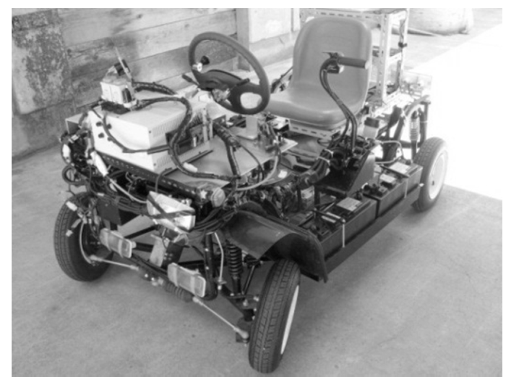
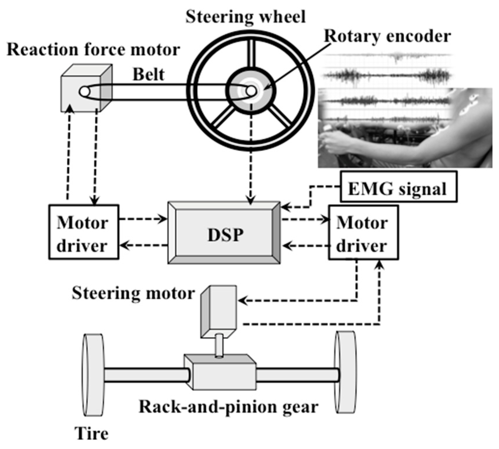
Figure 1 shows a photograph of the experimental vehicle. In this figure, we improved the vehicle called Friendly Eco, which is a one-seater vehicle for a wheelchair made by Takeoka Automobile (Crafts Co., Ltd., Toyama, Japan). The steer-by-wire system and steering wheel reaction force device were installed as shown in
Figure 2. The reaction torque is the torque [N∙m] at which the steering wheel’s turning angle returns to 0°, which is the straight running condition.
Before remodeling this vehicle, it had a rack-and-pinion type steering mechanism. The steering angle of the steering wheel is detected using a rotary encoder and is input to a stepping motor for steering using wired communication in the form of an electric signal for driving a rack and pinion gear [
10]. The proposed driving assist system using SBWS is shown in
Figure 2. A digital signal processor (DSP in the figure) operates the steering motor installed in the rack-and-pinion gear and reaction force motor installed in the steering wheel, while taking into consideration the steering angle, tire angle, and driver muscle burden. In addition, as the vehicle was designed for a wheelchair, the seat of the ultra-compact vehicle COMS (old model) made by Toyota Auto Body (Co., Ltd., Aichi, Japan). is mounted in place of the driver’s seat. The relative positional relationship between the seat and the accelerator pedal is set such that it is the same as that of COMS. We have already built a system in which the setting of the tire turning angle can be altered with respect to the turning angle of the steering wheel, but in this paper, as it is a fundamental study, we proceeded experimentally with the same setting as a mechanical steering system. A brushless motor is used for the reaction force device, and an arbitrary reaction force can be generated by the controller.
Table 1 shows the specifications of the motors.
2.2. Experimental Method on Changing Reaction Torque
In this control system, the steering angle of the driver is detected using a rotary encoder, and based on the steering angle signal, a microcomputer (Arduino UNO) is used to output a voltage proportional to the turning angle of the steering wheel to the motor driver and to control the outputs of the reaction force device.
The reaction force motor is controlled in order to change the reaction torque according to the steering angle. In this experiment, as shown in
Figure 3, the reaction torque applied to the steering wheel had three patterns.
Figure 3a shows the pattern without a feedback condition with a maximum reaction torque of 2.1 N·m as the output at any steering angle. In a conventional mechanical steering system, the lateral force exerted on the tires increases as the steering angle increases, and a generated self-aligning torque acts on the steering wheel. As shown in
Figure 3b, this condition was reproduced as a monotonically increasing function by linearly varying the reaction torque from 0 N·m to a maximum of 2.1 N·m. In this regard, the result of a static experiment of a previous study showed that the burden on the anterior deltoid increases as the steering angle also increases [
9]. In addition, the curve in
Figure 3c, which traces the change in the reaction torque, shows that the reaction torque reduced linearly from 2.1 to 0 N·m as the steering angle increased.
3. Physique of the Subjects and Posture during Steering Operation
The test subjects were 15 healthy male undergraduate students, each with a passenger vehicle driver’s license. Prior to the experiment, the extent of participation was explained to the prospective participants. Those amenable to participating signed an agreement that was approved by the Tokai University Ethics Committee for “research on human beings”, which also approved the experiment.
Table 2 shows the parameter values for all the subjects. To measure the weight of the arm, we instructed that the subjects’ arm should be level with the ground, with the arm lightly bent. Then, the arm was placed on the electronic balance at the state where no force was put on the shoulder, and the weight of the arm was measured.
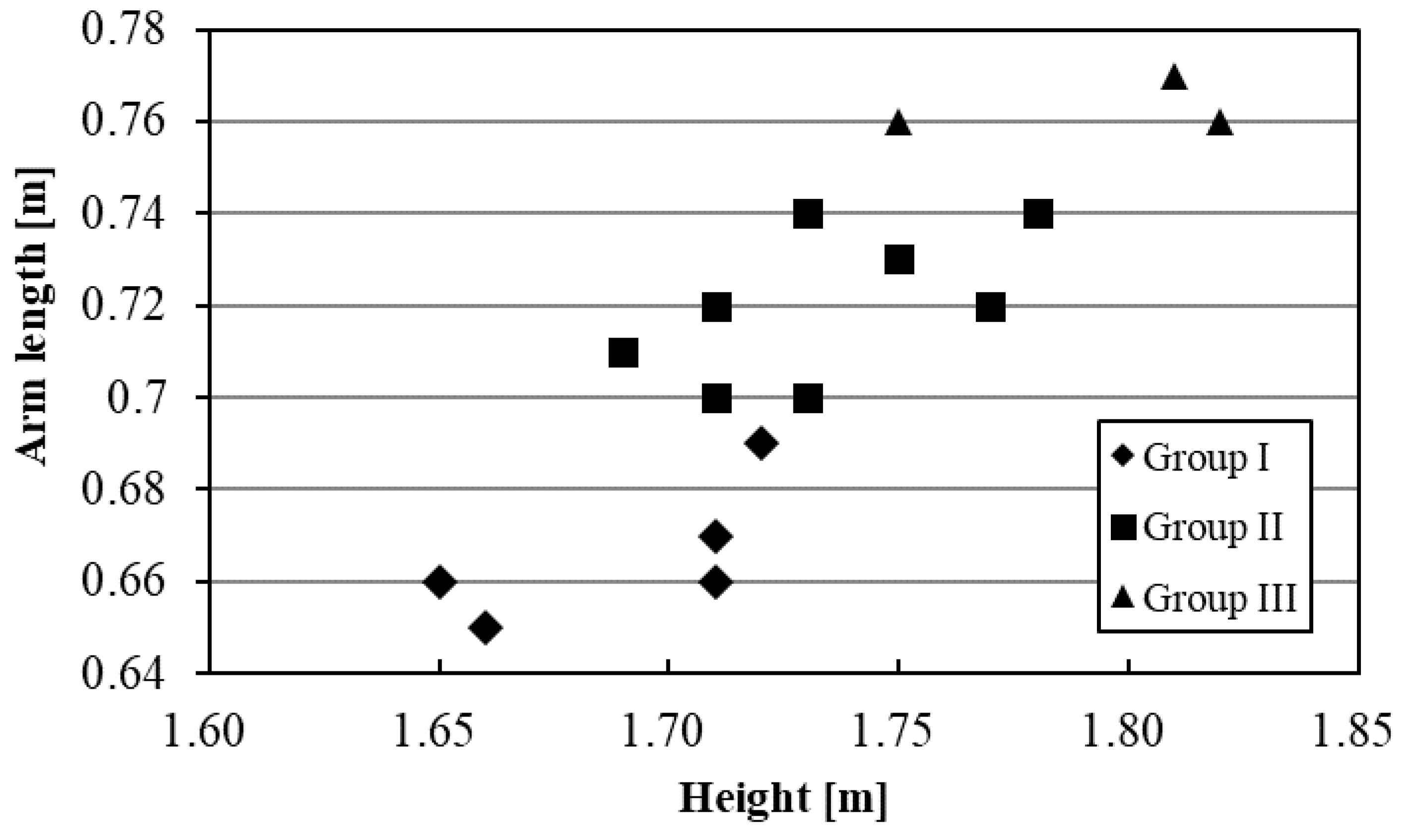
Figure 4 shows the relationship between the height and full arm length of all the 15 subjects. From the table, it can be observed that there is a difference of 0.12 m from the shortest arm length of 0.65 m to the longest arm length of 0.77 m, depending on the physique of the subject. In addition, it was found that the height was roughly proportional to the full arm length, and it was revealed that subjects with a higher height had longer arms.
The 15 subjects were subsequently divided into three groups based on the full arm length. The arm lengths in groups I–III were less than 0.70 m, more than 0.7 m but less than 0.75 m, and 0.75 m or greater, respectively. The plots of each group are different in
Figure 4.
Figure 5 shows an example of the relationship between the shoulder joint angle
θ and steering angle
φ during the steering operation in each group. On comparing each group, it was found that the opening angle of the shoulder joint decreases as the full arm length increases. This indicates that when the position of the steering wheel and driver’s seat are fixed, the greater the full arm length is, the easier it is to operate the steering wheel with a smaller shoulder joint angle.
4. Calculation of Shoulder Moment during Steering Operation
In order to investigate the burden on the upper arm, which is the pushing side arm from the viewpoint of dynamics, the moment around the shoulder joint was calculated with respect to the turning angle of the steering wheel during the driving operation posture. Focusing on the movement of the arm on the pushing side, the upper arm only moves vertically when the subject operates the steering wheel, and the forearm moves almost horizontally. Therefore, we considered that there was no big difference in model aspect in order to evaluate the muscle burden, and the moment around the shoulder was calculated in the front plane. The defined angle
θ of the shoulder joint was obtained by having the subject grip the steering wheel at each steering angle and measuring the angle of the shoulder joint portion from the right side of the subject (
Figure 5).
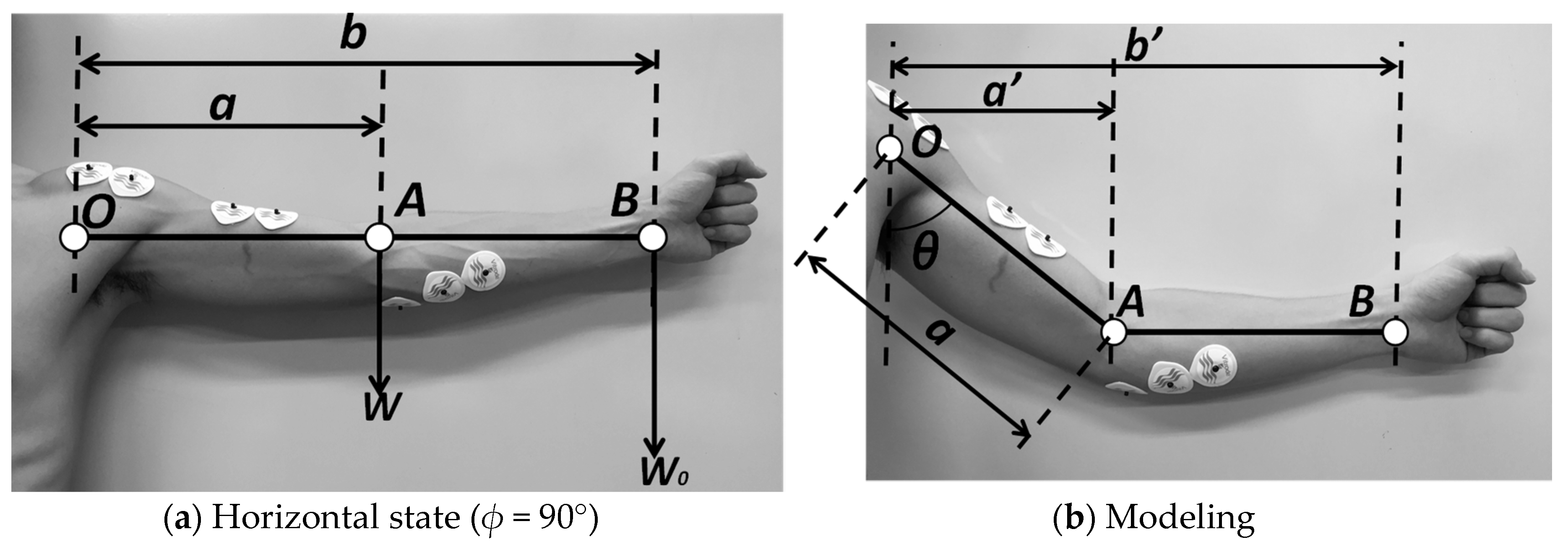
Based on the above results, the moment applied to the shoulder joint is calculated using the model shown in
Figure 6 for the upper arm. The parameter
a represents the distance from the shoulder joint to the center of gravity of the arm [m],
b represents the distance from the shoulder joint to the fingertip [m],
W represents the weight of the arm [kgf], and
W0 represents the reaction force generated in the steering wheel [kgf]. Point A in the figure is the elbow joint of the arm, and this point was taken as the center of gravity of the arm [
11]. Point B is the point at which the steering wheel is gripped, and the reaction force by the steering wheel acts at this point.
Using this model, the moment with respect to the angle
θ of the shoulder joint is as follows. It is assumed that the arm extends almost horizontally when the steering angle
φ = 90° (
Figure 6a), the weight
W of the arm and the reaction force
W0 generated in the steering wheel act vertically on the arm, and the lengths of the moment of
W and
W0 are
a and
b, respectively. Therefore, the moment about the shoulder joint (point O), which is represented by
M0, is
In contrast, in the model wherein the arm flexes, the distance
a′ from the shoulder joint to the center of gravity of the arm (
Figure 6b), which is represented by
a′, is
The distance from the shoulder joint to the steering wheel, which is represented by
b′, is
The moment
M1 around the shoulder joint is calculated using
a′ and
b′, which are obtained using Equations (2) and (3) as follows.
5. Evaluation of EMG and Experimental Result
5.1. Operability of the Steering Wheel and Muscle Activity of the Upper Arm
When the relationship between the steering wheel and tire turning angle is constant, the factors affecting the operating ability of the driver are as follows: the steering angle of the steering wheel, reaction torque transmitted from the steering wheel to the driver, and steering speed.
The reaction torque generated in the conventional mechanical-type steering wheel is due to the self-aligning torque (restoring torque), which works to eliminate the side slip angle of the rolling tire and return it to a straight line [
3]. This means that when the turning angle of the steering wheel, road surface condition, and vehicle speed are constant, the reaction torque of the steering wheel is also constant, but the reaction torque generated in the steering wheel varies depending on the road surface and driving conditions. Several studies on the steer-by-wire system [
12,
13] report that it is difficult to estimate the road conditions because the change in reaction torque is not transmitted to the driver. In this paper, in order to examine the muscle burden due to the difference in the physiques of the drivers, we conducted experiments using the same turning angle of the steering wheel and the same cabin layout. The reaction torque generated in the steering wheel was set as shown in
Figure 3.
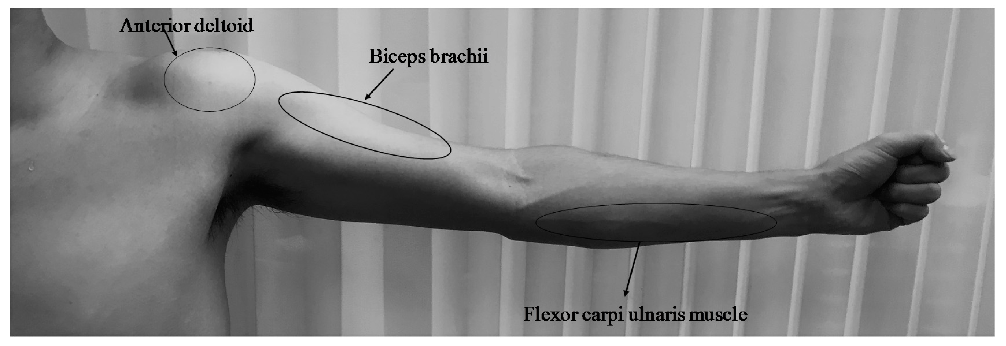
In this section, an overview of the muscle activities of the left and right arms of the driver is observed through surface myoelectric potential monitoring for the cases wherein the steering wheel is turned at a constant steering angle in order to identify the specific muscle to be considered for this study. The representative muscle activities of the left and right arms of the driver when operating the steering wheel at a constant steering speed were examined using surface EMG. As shown in
Figure 7, the muscles that are indispensable for the movement of the arm in the driving operation are the anterior deltoid, biceps brachii, and flexor carpi ulnaris. It is known from conventional research that the anterior deltoid is the most active when a steering operation is being performed at a constant steering angle [
9,
14]. Therefore, in this paper, the examined target muscle was the anterior deltoid, which is most involved in shoulder movement.
The surface EMG was amplified using a Bio Amp ML 132 (AD Instruments, Sydney, Australia) and recorded at a sampling frequency of 4 kHz using an A/D converter (Power Lab ML 825 2125, AD Instruments, Sydney, Australia) [
5]. The positions of the electrodes are shown in
Figure 8.
5.2. Measurement and Results
To evaluate the muscle burden, we carried out a steering wheel operation experiment and measurement of the surface EMG. The reaction torque of the steering wheel was changed in three patterns, as shown in
Figure 3, according to the steering wheel angle. In order to consider the subject’s dominant arm, subjects operated the steering wheel in a clockwise and counter-clockwise direction. In each direction, we measured the EMG of the anterior deltoid on the side that pushes the steering wheel. In each direction, we measured the EMG of the anterior deltoid on the pushing side where we have previously confirmed that the subjects feel the most burden. Therefore, we measured surface EMG of the left arm in the case of the clockwise direction, and surface EMG of right arm in the case of the counterclockwise direction. The measurement of the surface EMG at the anterior deltoid was recorded using the same method as that in the previous section, and the root mean square of the 0.1 s interval was calculated every 0.1 s for the EMG waveform. As there are individual differences in the demonstration of the muscular strength, an evaluation is performed using %MVC while showing the ratio of the EMG at the time of the experiment to the maximum myoelectric potential (MVC) at the time when the maximum muscular strength was exhibited. The measurement of MVC requires that the subject extend their arm forward such that it is level with the ground and use the maximum force in this state. In order to prevent the arm from rising above the shoulder, it was pushed down from above by the experimenter, and the measurement was obtained over 5 s. The posture of the driver at the condition at which the vehicle is stopped was considered as the normal driving posture, and the holding positions of the hands on the steering wheel were set to the 9 o’clock and 3 o’clock positions. In this case, the operation time was maintained at 2 s using a metronome operating at 60 bpm. Ten measurements were obtained for each of the three patterns of the varying reaction torque applied to the steering wheel, and the average value was calculated.
Figure 9 shows the experimental result of %MVC at the anterior deltoid of three subject groups in the case of three reaction torque patterns, as shown in
Figure 3. By changing the reaction torque by SBWS like the pattern of Decrease (
Figure 3c), about 40% muscle burden can be reduced, regardless of the subject group, compared with the torque pattern of Constant (
Figure 3a) of the conventional steering system using the rack and pinion mechanism. On examining the measurement results of the deltoid muscle surface EMG potential in three groups (
Figure 9), it was found that the shorter the full arm’s length, the lower the burden on the shoulder regardless of the subject’s dominant arm. It is speculated that this is because the longer the full arm’s length is, the greater the moment acting at the shoulder is.
Figure 10 shows the moment applied to the shoulder joint when the reaction force control is performed with three patterns of groups using the steering angle feedback control in
Section 2.2. From the figure, it can be observed that a larger moment acts on the subjects with longer arms. It was also found that a difference of approximately 8 N∙m occurs when the full arm’s length differs by 0.1 m.
From these results, it became clear that the different physiques of the subjects affect the muscle burden of the upper arm when the position of the steering wheel and the driver’s seat are fixed, as in the case of the ultra-compact mobility vehicle. Furthermore, the control used in this study is considered to be effective for reducing the muscle burden on the upper arm of the driver.
6. Conclusions
In this study, a fundamental investigation was performed on the evaluation of the surface EMG and calculation of the dynamics concerning the effect of reducing the upper arm burden of drivers with different physiques on using an ultra-compact mobility vehicle equipped with a steer-by-wire system. In the steering operation of the arm, it was shown that the anterior deltoid of the pushing side arm was the most active muscle when performing the steering operation in the same seat position. In the case of all the patterns of the reaction torque control, it was found that the muscle burden of the subjects with long arms increases by 25% compared to the subjects with short arms.
In addition, when the driver operated the steering wheel with a constant reaction torque, the moment increases as the turning angle of the tires increases due to the opening angle of the shoulder joint, and it was confirmed that the burden on the anterior deltoid supporting the upper arm increased. As the turning angle of the steering wheel changed, it was possible to reduce t by approximately 40% of the muscle burden compared to the conventional reaction torque pattern, by decreasing the reaction force regardless of the subjects’ physique.
Furthermore, in the steering angle feedback reaction torque control proposed in consideration of the above tendency, it is clarified that a reduction in the muscle burden can be expected on decreasing the steering reaction torque at the turning angle at which the moment is large owing to the opening angle of the shoulder joint. It was also found that the burden can be reduced by the change of the steering reaction force, even with the steering time of 2 s. Therefore, it is considered that the steering angle feedback reaction torque control is effective, even for drivers of different physiques in ultra-compact mobility vehicles, for which it is difficult to consider an appropriate driving position from the viewpoint of operability. In this paper, we conducted tests for only male subjects; however, we will conduct tests for female subjects and further discuss the implications of various physiques. Furthermore, we will model the upper limb in detail and consider a wider range for the operation angle of the steering wheel.
Author Contributions
Conceptualization, T.N. and H.K.; Methodology, H.K.; Software, M.H.B.P. and T.N.; Validation, M.H.B.P., A.E. and K.I.; Formal Analysis, M.H.B.P., A.E. and K.I.; Investigation, X.L., A.E. and K.I.; Data Curation, D.U.; Writing-Original Draft Preparation, X.L.; Writing-Review & Editing, T.N. and H.K.; Visualization, D.U.; Supervision, H.K.; Project Administration, H.K.
Funding
This research received no external funding.
Conflicts of Interest
The authors declare no conflict of interest.
References
- Kuramori, A.; Koguthi, N.; Kamijo, M.; Sadoyama, T. Study on Driving Ease Evaluation Focusing on Muscular Activity of Driver. J. Soc. Automot. Eng. Jpn. 2007, 61, 116–121. [Google Scholar]
- Kuramori, A.; Sakai, D.; Kamijo, M. Study on Driving Fatigue Evaluation by Using Driver's Electromyogram. Trans. Soc. Automot. Eng. Jpn. 2010, 41, 489–493. [Google Scholar]
- Han Kim, K.; Martin, B.J.; Chaffin, D.B. Modeling of shoulder and torso perception of effort in manual transfer tasks. Ergonomics 2004, 47, 927–944. [Google Scholar] [CrossRef] [PubMed]
- Dickerson, C.R.; Martin, B.J.; Chaffin, D.B. Predictors of perceived effort in the shoulder during load transfer tasks. Ergonomics 2007, 50, 1004–1016. [Google Scholar] [CrossRef] [PubMed]
- Pick, A.J.; Cole, D.J. Driver steering and muscle activity during a lane-change manoeuvre. Int. J. Veh. Mech. Mobil. 2007, 45, 781–805. [Google Scholar] [CrossRef]
- Yang, Y.; Liu, Y.; Wang, M.; Ji, R.; Ji, X. Objective evaluation method of steering comfort based on movement quality evaluation of driver steering maneuver. Chin. J. Mech. Eng. 2014, 27, 1027–1037. [Google Scholar] [CrossRef]
- Pick, A.J.; Cole, D.J. Measurement of driver steering torque using electromyography. J. Dyn. Syst. Meas. Control 2006, 128, 960–968. [Google Scholar] [CrossRef]
- Liu, Y.; Ji, X.; Hayama, R.; Mizuno, T.; Lou, L. Function of shoulder muscles of driver in vehicle steering maneuver. Sci. Chin. Technol. Sci. 2012, 55, 3445–3454. [Google Scholar] [CrossRef]
- Umemoto, T.; Liu, X.; Narita, T.; Kato, H.; Moriyama, H. Steer-by-wire system for ultra-compact electric vehicle (Fundamental consideration on the burden of the push side upper arm using EMG of anterior deltoid). J. Jpn. Soc. Appl. Electromagn. Mech. 2017, 25, 155–161. [Google Scholar] [CrossRef]
- Takebayashi, A.; Sakamoto, H. Development of a small-sized electric vehicle have driving control mechanism by steer-by-wire. In Proceedings of the Conference on Chugoku-Shikoku Branch Japan Society of Mechanical Engineers, Tokushima, Japan, 3–6 March 2007. [Google Scholar]
- Özkaya, N.; Leger, D.; Goldsheyder, D.; Nordin, M. Fundamentals of Biomechanics: Equilibrium, Motion, and Deformation; Springer: New York, NY, USA, 1999. [Google Scholar]
- Raksincharoensak, P.; Watanabe, S.; Shino, M.; Nagai, M. Front steering control of steer-by-wire based on four-wheel-steering theory. Trans. Soc. Automot. Eng. Jpn. 2005, 36, 141–146. [Google Scholar]
- Tomita, K.; Pongsathorn, R.; Nagai, M. Enhancing Vehicle Handling and Stability by Integrated Control of Independent In-Wheel-Motors and Steer-By-Wire. In Proceedings of the Transportation and Logistics Conference, Kawasaki, Japan, 7–9 December 2005. [Google Scholar]
- Yoshida, T.; Hase, K.; Obinata, G.; Hada, M. Analysis of steering operation using a 3-dimentional musculo-skeletal model of the upper extremities and evaluation about the design parameters of steering wheels. J. Soc. Biomech. 2010, 34, 41–52. [Google Scholar] [CrossRef]
© 2018 by the authors. Licensee MDPI, Basel, Switzerland. This article is an open access article distributed under the terms and conditions of the Creative Commons Attribution (CC BY) license (http://creativecommons.org/licenses/by/4.0/).
