Abstract
Reducing iron loss in axial flux permanent magnet (AFPM) motors is critical for improving efficiency. This study proposes a design-optimization procedure that combines 3D finite-element analysis (FEA) data with an artificial neural network (ANN) surrogate. For four design variables—airgap length, rotor back-yoke thickness, stator slot width, and stator slot depth—the search bounds were defined to avoid tooth and back-yoke saturation, and the corresponding space was sampled to construct a dataset. Using this dataset, the ANN was trained and then used to explore low-iron loss solutions. On an independent validation set, ANN predictions showed high agreement with 3D-FEA reference values, enabling rapid evaluation of many design candidates. As a result of the optimization, total iron loss decreased relative to the baseline, and torque increased by 3 Nm. These results demonstrate that the ANN-based surrogate model can reliably perform geometry-dependent iron loss optimization in AFPM motors, providing a fast and accurate alternative to repetitive 3D-FEA evaluations.
1. Introduction
Axial flux permanent magnet (AFPM) motor is attracting attention as one of the core driving sources of next-generation electric vehicle (EV) driving systems. AFPM motors have advantages such as high efficiency, excellent torque density, and lightweight structure, and can be flexibly applied even in environments with large space constraints [1,2,3]. AFPM motors have various topologies depending on the number of rotors and the arrangement of permanent magnets, among which the structure in which the stator yoke is removed shortens the magnetic flux path, effectively reducing the iron loss [4,5]. This structure is called the yokeless and segmented armature (YASA) topology and is evaluated as a structure with high potential in EV drive system design that requires high efficiency and weight reduction [2].
Accurate prediction of iron loss in the design of AFPM motors is very important. Excessive loss not only lowers the efficiency of the motor but also causes thermal instability and mechanical degradation [6]. In AFPM machines, the axial flux path and strong harmonic components make the iron loss more sensitive to geometric variations than in radial-flux machines, which further highlights the need for accurate iron loss modeling. However, 3D-FEA is inefficient for iterative optimization design due to long computation time and high resource consumption. To solve this problem, research has been actively conducted to quickly and efficiently predict loss characteristics using neural networks and data-driven alternative models [7].
In the design process of an electric machine, it is not enough to simply present the theoretical validity; the actual implementability and design efficiency must be considered together. An axial magnetic flux type permanent magnet motor was designed using the ANSYS Maxwell 2025 R2 and various variable ranges were set to review the optimized performance. Based on the data obtained from this, an artificial neural network (ANN) model was constructed. ANN is a nonlinear approximation model that mimics the structure of a human neural network and consists of an input layer, a hidden layer, and an output layer. Each node performs a nonlinear transformation through a weight and an activation function and learns complex relationships between data. ANN is trained to predict output variables based on input variables and repeatedly optimizes input–output relationships through supervised learning. In the learning process, the weights are adjusted to minimize loss, and thus ANN may be precisely modeled [8,9]. After training, the ANN can provide fast and reliable predictions, which significantly reduces the computational burden of repeated 3D-FEA evaluations and allows efficient exploration of candidate designs [10].
In [11], Garmut et al. proposed a computationally efficient multi-objective optimization framework for IPMSMs by training neural-network-based surrogate models on 2D-FEM-derived intermediate torque and flux linkage data. In [12], Gao et al. introduced an NN-assisted analytical correction approach for PMSM mass and loss estimation, focusing on mass loss optimization rather than 3D iron loss modeling. In [13], Guo et al. introduced a machine learning-based surrogate for IPMSM design using 2D coarse–fine FEA data, focusing on torque–cost–weight optimization rather than loss-oriented optimization. For AFPM machines, Kim et al. [14] performed a multi-objective optimal design of an in-wheel axial flux permanent magnet motor, primarily targeting torque ripple mitigation and electromagnetic performance improvement. However, their approach depended on metamodel-based numerical optimization rather than NN-driven surrogate learning, and iron loss prediction using 3D transient FEA was not considered. In [15], Vatani et al. proposed a hybrid optimization method for coreless axial flux PM machines that integrate differential evolution with an NN-based surrogate trained on 3D-FEA data, substantially reducing reliance on direct FEA evaluations. Because the machine employs a coreless stator, iron loss is negligible, and the optimization therefore focuses on minimizing active mass and Joule loss rather than iron loss reduction.
Considering these circumstances, this study focuses on determining whether an ANN-based surrogate model can effectively reduce the computational burden of repetitive 3D-FEA while still providing accurate prediction and minimization of iron loss in a YASA-type AFPM motor. As this work represents the initial stage of applying neural networks to AFPM motor optimization, iron loss was deliberately selected as the first objective because it is directly governed by electromagnetic geometry and therefore provides the most appropriate and physically meaningful quantity for validating the surrogate model. The primary purpose of this study is to demonstrate that ANN can reliably support geometry-based optimization and significantly reduce computation time. Building upon this verification, future research will extend the surrogate framework to additional objectives such as copper loss, PM eddy loss, thermal behavior, and mass for comprehensive multi-objective optimization.
To address the identified research gap, this work proposes an ANN-based iron loss prediction and optimization framework tailored specifically for a YASA-type AFPM motor. The main contributions of this study are as follows:
- (1)
- It focuses on iron loss minimization in an AFPM motor, an aspect that has been insufficiently explored in previous machine-learning-based optimization studies;
- (2)
- The ANN model is trained using complete 3D-FEA data rather than the simplified 2D-FEA;
- (3)
- The proposed workflow significantly reduces the total 3D-FEA computation time while maintaining reliable prediction accuracy, thereby enabling practical and efficient design optimization.
2. Overview of the AFPM Motor Design
2.1. AFPM Motor Topologies and Structure
AFPM motors can be classified into several topological structures depending on the arrangement of stators and rotors. Figure 1 illustrates four typical configurations: single-stator single-rotor (SSSR), double-stator single-rotor (DSSR), single-stator double-rotor (SSDR), and multi-stator multi-rotor (MSMR). Each topology offers distinct advantages and limitations, making it suitable for specific applications. The SSSR topology consists of a single stator and a single rotor. This configuration is structurally the simplest among AFPM designs and offers high power density due to the short axial length and direct magnetic coupling between the stator and rotor. However, because the magnetic attraction between the stator and rotor is unbalanced, the SSSR topology experiences significant axial magnetic forces. This imbalance can lead to increased vibration, mechanical stress on bearings, and reduced operational lifetime, particularly in high-speed applications. The DSSR topology incorporates two stators positioned on either side of a single rotor. This arrangement balances the axial forces acting on the rotor, reducing vibration and improving mechanical stability compared to SSSR. Depending on the design, the permanent magnets can be mounted on the rotor surface or embedded within the rotor core. Surface-mounted designs are generally easier to manufacture, whereas embedded designs protect the magnets from mechanical damage and demagnetization. DSSR motors are particularly suited for applications that require moderate axial compactness while maintaining mechanical robustness. The SSDR topology features a single stator placed between two rotors. This design provides inherent axial force balancing because the magnetic attraction from each rotor acts in opposite directions on the stator. As a result, SSDR motors exhibit reduced bearing loads and enhanced structural stability, making them advantageous for high-torque and high-reliability applications. Furthermore, the doubled rotor surface area increases the torque output without increasing the motor diameter, thereby improving torque density [1,16].
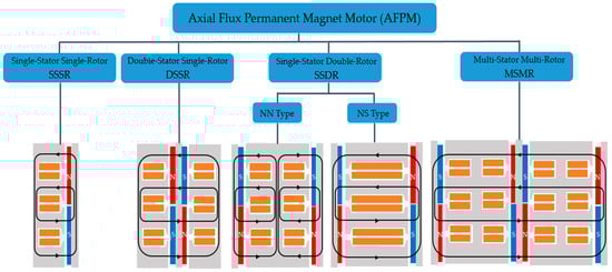
Figure 1.
Topological structure of AFPM motor.
In the SSDR configuration, the arrangement of the rotor permanent magnets can be further categorized into NN-type and NS-type. In the NN-type configuration, both rotors present the same magnetic pole toward the stator. This design emphasizes higher flux linkage in certain winding arrangements but may result in a more complex leakage flux pattern. Conversely, the NS-type configuration aligns the rotors so that opposite poles face the stator. This arrangement creates a more uniform magnetic field distribution, reduces leakage flux, and can improve the back-EMF waveform quality. The NS-type is often preferred in applications where torque ripple reduction and electromagnetic performance optimization are critical [1]. The MSMR topology consists of multiple stators and multiple rotors, typically in an alternating sequence. This modular approach allows the motor scaling for higher torque and power output without significantly increasing the outer diameter. MSMR motors are particularly advantageous for large-scale propulsion systems, such as marine drives and wind turbine generators, where maximizing torque density and maintaining a compact radial dimension are essential. However, the increased number of active components results in greater manufacturing complexity and higher material costs [17].
The YASA topology is a specialized variant of the AFPM motor that eliminates the continuous yoke in the stator and employs segmented armature teeth [2,18], as illustrated in Figure 2. Instead of a conventional ring-shaped stator core, the stator is composed of discrete, individually wound tooth segments that are positioned between two rotor discs. Each segment is mechanically fixed and electrically connected to form the complete stator winding configuration. By removing the stator yoke, the magnetic flux path between the rotor permanent magnets and the stator teeth becomes shorter and more direct. This design reduces the overall mass of active materials, particularly iron, which leads to lower iron losses and improved efficiency [5,19]. Furthermore, the absence of a continuous yoke reduces the circumferential flux leakage, thereby enhancing the effective utilization of the magnetic flux generated by the permanent magnet. One of the key advantages of the YASA topology is its high torque density. The double-rotor, single-stator arrangement inherently balances axial forces, minimizing mechanical stress on the bearings. Additionally, the segmented stator construction facilitates modular manufacturing, allowing for simplified coil winding, improved cooling access, and straightforward replacement or maintenance of individual segments. The modular nature of the stator also enables scalable manufacturing, as the same segment design can be used to assemble motors of varying diameters and ratings. From a thermal management perspective, the segmented armature structure provides increased surface area and open pathways for airflow or liquid cooling, resulting in improved heat dissipation from the stator windings. This thermal advantage allows the motor to sustain higher continuous current densities without overheating, which directly contributes to higher continuous torque output [5].
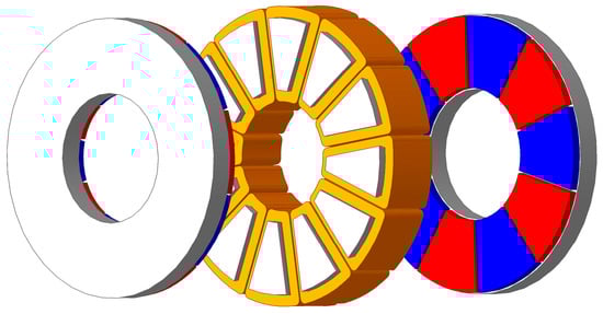
Figure 2.
The YASA type AFPM motor.
2.2. General Sizing Equation of AFPM Motor
The design starts with estimating the external size of the AFPM motors to meet the power/torque requirements under the given constraints [2,16]. Assuming negligible stator-armature leakage inductance and resistance, the output power for an AFPM motor can be expressed as Equation (1).
where and are the stator-armature phase back-emf and its amplitude (or peak value), respectively; and denote the stator-armature phase current and its amplitude, respectively; , and represent the motor efficiency, the total number of phases on the stator, and the period of one back-emf cycle, respectively; is termed the electric power waveform factor, defined by Equation (2).
For the AFPM motor, the amplitude of the phase back-emf in Equation (1) has the following form:
where is the back-emf factor the armature-winding distribution factor; denotes the number of turns in series per armature-winding phase; represents the main electrical frequency; p defines the number of machine pole pairs; are the diameters of the inner and outer surfaces of the AFPM motor, respectively, being the inner-to-outer diameter ratio; represents the peak value of the magnetic flux density in the airgap (magnetic loading). To emphasize the effect of the armature-winding phase current waveform, the factor is expressed in Equation (4).
denotes the armature-phase current rms value. The peak value of the armature winding phase current is thus given by
where represents the peak value of the line armature-winding current density per stator active surface (electric loading) since it is expressed at the average diameter of the airgap in Equation (5); denotes the number of armature-winding phases per stator.
Based on the above equations, a general-purpose sizing equation for the AFPM motor can be obtained, as expressed in Equation (6).
2.3. Determining the Loading Ratio for Geometric Detail
The loading ratio is determined by fixing the stator-to-rotor proportion. In AFPM motors with short axial length, design considerations are saturation in the stator–rotor airgap and saturation of the rotor back yoke. The airgap flux density is limited to 1.05 T. To avoid performance degradation caused by rotor saturation under load, the loading ratio is selected so that the rotor flux density remains within 1.2–1.6 T [20].
3. Electromagnetic Characteristic Analysis
3.1. Magnetic Field Analysis
The AFPM motor features a unique structure that operates based on the principle of electromagnetic induction. As shown in Figure 3, the motor’s magnetic flux predominantly flows along the axial direction. The generated magnetic field interacts with the magnetic field of the rotor’s permanent magnets to form a closed magnetic flux circuit [21].
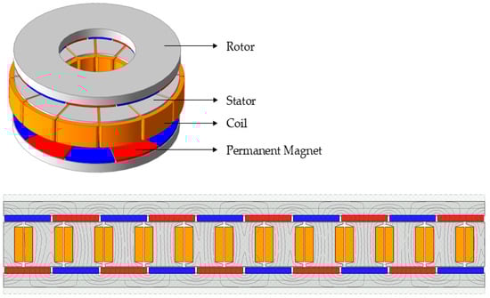
Figure 3.
AFPM motor in 2D and 3D.
The magnetic flux density distribution in the designed AFPM motor was analyzed through 3D-FEA. The airgap flux density, shown in Figure 4, was maintained below 1.05 T, ensuring that the magnetic circuit operates within the unsaturated region.
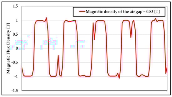
Figure 4.
The magnetic flux density of the airgap.
The magnetic flux density in the rotor back yoke and stator teeth, illustrated in Figure 5, remained below 1.6 T, indicating that magnetic saturation does not occur in these regions. These results confirm that the designed structure achieves an optimal magnetic flux distribution while effectively preventing excessive magnetic saturation.
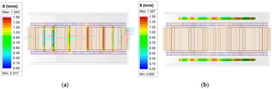
Figure 5.
The magnetic flux density in the rotor back yoke and stator teeth: (a) stator teeth; (b) rotor back yoke.
3.2. Transient Analysis
When sinusoidal currents are applied to each of the three-phase windings of the AFPM motor, the motor speed and phase currents remain stable, and the torque output satisfies the design specifications. As shown in Figure 6, the motor achieves a peak torque of 365 Nm at a speed of 4500 rpm, demonstrating stable operation under load conditions.
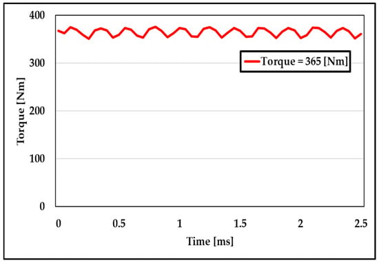
Figure 6.
The output torque of the AFPM motor.
3.3. Iron Loss Analysis
Iron loss is induced in the ferromagnetic components due to the variation of the magnetic field generated by the stator windings and the rotation of the permanent magnets.
Accurate calculation of iron loss is one of the most critical and complex tasks in the design and optimization of AFPM motors. Iron loss consists of hysteresis loss, eddy current loss, and excess loss [22].
Each component of the iron loss is modeled using the following empirical equation:
where is the total iron loss and represent the hysteresis, eddy current, and excess loss, respectively; The coefficients and denote the respective loss coefficients; is the frequency; is the maximum magnetic flux density; and is the core flux density coefficient.
The material used to manufacture the stator segments and rotor yoke is SMC, which is produced by the company Höganäs AB (Höganäs, Sweden). The iron loss of SMC at various frequencies and different levels of magnetization is measured by the manufacturers. With the measured data, the constants in the coefficients are determined with the curve fitting tool.
The parameters of the SMC material are input into the MAXWELL ANSYS for calculation, and the iron loss can be obtained [23], as shown in Figure 7.
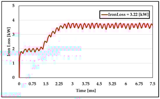
Figure 7.
AFPM motor iron loss.
3.4. Efficiency
The calculation formula for motor efficiency is as follows [21]:
where is the rated output power of the motor, is copper loss, is the eddy current loss of the permanent magnet, and is the mechanical loss of the rotor. In AFPM motors, mechanical loss must be considered when calculating efficiency; it consists of two components: bearing friction and rotor windage loss. Because mechanical loss is difficult to calculate accurately, it is computed according to the following empirical formula:
The electromagnetic loss components of the motor are summarized in Table 1, and, according to Equation (11), the efficiency is 85.8%.

Table 1.
Electromagnetic component loss table.
4. ANN-Based Iron Loss Reduction and Design Optimization
4.1. Iron-Loss Optimization
In this paper, the motor optimization goal is set and improved using the artificial neural network (ANN) for iron loss optimization. The detailed optimization process is shown in Figure 8.
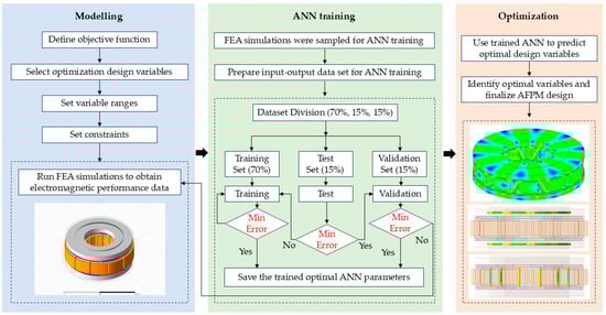
Figure 8.
Optimization process of the AFPM motor.
4.2. Determination of AFPM Parameter Variables
Inspired by an ANN to decrease the iron loss of AFPM, design variables and the results of crossing these variables design parameters are evaluated.
The main design parameters affecting the iron loss are airgap (g), depth of the rotor yoke (dry), width of the stator slot (wss), and depth of the stator slot (dss). The geometric locations of these variables within the AFPM motor are illustrated in Figure 9. Since iron loss is highly dependent on magnetic flux density, structural variations directly affect the flux distribution. Therefore, the parameter ranges were determined so that the flux density in the stator teeth and rotor back yoke remain within 1.2–1.6 T, avoiding magnetic saturation, and the selected ranges of these variables are summarized in Table 2.
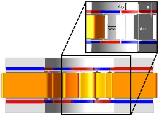
Figure 9.
Variable of AFPM.
Table 2.
Optimize the range of values of variables.
4.3. ANN-Based Model
ANNs can be used for developing models based on the input-output data obtained from simulation tools or measurements. In fact, ANNs provide new fast solutions to replace conventional methods, such as numerical modeling techniques, that have costly computations or analytical methods, which could be hard to get for new components or empirical models, which have a restricted range and accuracy [8]. ANNs are composed of interconnected neurons and weighted connections, forming multilayer architectures such as multilayer perceptrons (MLPs) that enable nonlinear function approximation [24,25,26].
A neural network-based surrogate model was employed to replace repetitive 3D-FEA evaluations during the optimization process, as illustrated in Figure 10. Unlike analytical iron loss formulations, the ANN directly learns the nonlinear relationship between the geometric parameters and the resulting iron loss using the dataset generated from 3D-FEA.
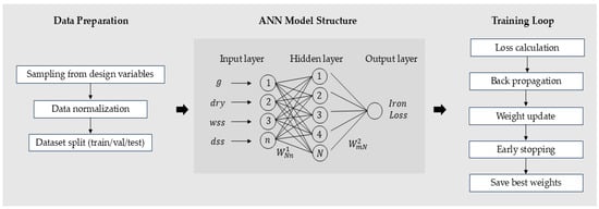
Figure 10.
ANN modeling and training process.
The dataset consisted of four geometric variables (g, dry, wss, and dss) and corresponding iron loss values, which were normalized and divided into training, validation, and testing subsets. An MLP architecture was selected due to the nonlinear behavior of iron loss in AFPM motors. The final model consisted of one input layer with four neurons, two hidden layers with optimized neuron counts, and one output neuron representing iron loss. Hyperparameters such as activation functions, learning rate, solver, and regularization term were tuned through preliminary experiments to minimize prediction error. ReLU activation was used in the hidden layers owing to its strong nonlinear approximation capability, while a linear activation was used in the output layer.
To enhance generalization, early stopping and validation-based monitoring were applied to avoid overfitting and prevent the model from learning FEA noise. Because the ANN surrogate evaluates a design in milliseconds, it enables rapid exploration of the design space, which would otherwise be computationally infeasible using 3D-FEA alone.
4.4. Performance of the ANN
The neural network achieved the best validation performance at 16 epochs. Figure 11 shows the mean square error (MSE) distribution for the training, testing, and validation datasets, indicating similar loss trends among the datasets and confirming that overfitting did not occur. Figure 12 presents the regression relationship between the target and predicted values, where the regression line slope is close to 1, and the correlation coefficient (R2) is high, demonstrating that the ANN model achieved high reliability in predicting iron loss.
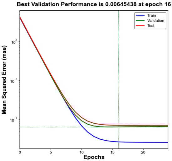
Figure 11.
Performance of ANN.
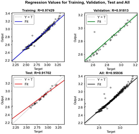
Figure 12.
Regression values of Training, Test, Validation, and All.
4.5. Application of the ANN
The trained ANN surrogate was then applied to all design combinations to predict iron loss. As shown in Figure 13, the ANN tracks the 3D-FEA trend across the entire set, with only two FEA dropouts appearing as outliers, while the ANN provides a smooth estimate. This confirms that the network generalizes well to different design values and is suitable for use in design optimization. The predicted iron loss values were ranked in ascending order, and the top-ranked combination was selected for the final optimized design, as listed in Table 3.
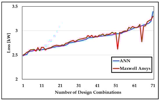
Figure 13.
Iron loss comparison ANN vs. 3D-FEA.
Table 3.
Optimized design parameters.
To further highlight the practical benefit of adopting the ANN surrogate model, the computation time required for one 3D-FEA iron loss evaluation was compared with that of a single ANN prediction. In our simulation environment, a single 3D-FEA transient iron loss calculation required approximately 10 to 14 h, depending on the mesh density and solver configuration. In contrast, the trained ANN surrogate model produced an iron loss prediction in less than 0.2 s. The training dataset used in this study consisted of 300 samples, each requiring 10–14 h of computation, resulting in an actual dataset-generation time of approximately 3000–4200 h. Although this offline cost is substantial, it is incurred only once during model development, and subsequent optimization no longer depends on 3D-FEA evaluations. When extended to the same number of candidate designs, the ANN surrogate required less than one minute to evaluate 300 samples, corresponding to an effective computational acceleration of approximately 104–105 times compared with direct 3D-FEA analysis. This clarification has been added to distinguish the actual dataset-generation time from hypothetical brute-force evaluation of the full design space. The FEA simulations were performed on a workstation equipped with a 12th Gen Intel® Core™ i9-12900K processor (16 cores, 3.19 GHz) (Santa Clara, CA, USA) and 96 GB RAM, running ANSYS Maxwell 2025 R2. The detailed comparison of computation time is summarized in Table 4.
Table 4.
Time comparison between 3D-FEA and ANN.
This substantial reduction in computation time confirms that the ANN is highly suitable for design optimization, where repeated evaluations are required.
4.6. Optimization Result
The efficiency, torque, and iron loss optimized by the ANN were compared with those of the baseline design. Figure 14 presents the optimized torque results, and Figure 15 shows the iron loss comparison. The pre- and post-optimization motor parameters and performances are summarized in Table 5.
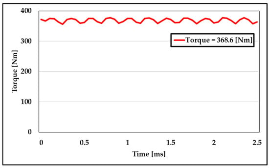
Figure 14.
Optimized torque.
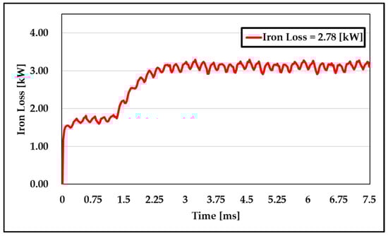
Figure 15.
Optimized iron loss.
Table 5.
Motor parameters and performance comparison table.
5. Discussion
Although the ANN surrogate significantly reduces the computational burden and enables rapid exploration of the design space, several inherent limitations remain. First, the prediction accuracy strongly depends on the quality, coverage, and consistency of the 3D-FEA dataset. Since the surrogate cannot reliably extrapolate beyond the sampled design region, designs outside the training distribution may lead to inaccurate or unstable predictions. Second, the ANN operates as a black-box model and therefore cannot provide physical insight into the underlying iron loss mechanisms. As a result, it cannot replace physics-based analysis when detailed electromagnetic interpretation or verification is required. Third, generating the training dataset itself is computationally expensive, as each 3D-FEA transient simulation requires several hours. If the dataset contains numerical noise or insufficient sampling density, the ANN may learn these artifacts, resulting in degraded generalization performance. For these reasons, the optimized design obtained from the surrogate model must still be validated using full 3D-FEA to ensure reliability.
In addition, although the efficiency improvement obtained in this study is modest, the primary objective of the proposed framework is not to maximize efficiency but to verify that an ANN surrogate trained on 3D-FEA iron loss data can effectively reduce the computational burden of iterative design exploration. Because the dataset generation is performed only once, the trained surrogate can rapidly evaluate thousands of candidate designs, making large-scale design exploration practically feasible. Such extensive evaluations would require a very long computation time when performed using direct 3D-FEA-based optimization, making this approach impractical for iterative design exploration. Therefore, despite the offline cost of generating the dataset, the surrogate model provides substantial practical usefulness by enabling rapid and repeated evaluation of thousands of candidate designs.
6. Conclusions
In this paper, an ANN-based design-optimization algorithm was proposed to reduce iron loss in AFPM motors. Design variables were defined, 3D-FEA simulations were conducted, and the resulting dataset was combined with an ANN to accelerate loss prediction and design exploration. The trained network was used to validate ANN-generated design solutions. The close agreement between the ANN predictions and 3D-FEA results under matched variable settings confirmed the predictive fidelity of the surrogate model, enabling the identification of high-performance designs. By evaluating many candidates in a short time, design combinations that minimized iron loss were discovered. Compared to the baseline, iron loss decreased, and torque increased by 3 Nm.
Although the efficiency gain was small, the significance of this work lies not in maximizing efficiency but in demonstrating that an ANN can reliably predict and minimize iron loss in an AFPM motor, providing a fast and accurate alternative to repetitive 3D-FEA evaluations. While motor design generally involves multi-objective considerations—such as mass, thermal behavior, and copper loss—these factors require prototype-based validation and multi-physics modeling. For this reason, the present study intentionally focused on iron loss to clearly demonstrate the effectiveness of the proposed ANN surrogate model for geometry-dependent loss prediction.
Furthermore, this work represents the initial stage of applying a neural-network-based surrogate to AFPM motor optimization. Iron loss was deliberately selected as the first objective because it is directly governed by electromagnetic geometry and therefore provides a reliable and physically meaningful target for verifying whether the ANN surrogate can accurately support optimization and significantly reduce computation time. Building upon this foundation, future work will extend the surrogate model beyond geometry-driven iron loss by incorporating additional winding-related variables to enable copper-loss-oriented optimization and, eventually, a multi-objective design framework that includes thermal behavior, mass, and overall efficiency.
In summary, focusing on iron loss allowed this study to evaluate the geometry-dependent electromagnetic behavior of the AFPM structure and to clearly validate the capability of the ANN surrogate model. Although optimization targeted only a single objective, the results demonstrate that the proposed approach provides a meaningful foundation for future comprehensive, multi-objective motor design studies.
Author Contributions
Conceptualization, S.-M.O. and H.-J.L.; methodology, S.-M.O.; investigation, S.-M.O.; resources, K.A. and D.-W.L.; writing—original draft, S.-M.O.; writing—review and editing, S.-M.O., K.A., D.-W.L., and H.-J.L.; supervision, H.-J.L. All authors have read and agreed to the published version of the manuscript.
Funding
This research was supported by the Korean Institute for Advancement of Technology (KIAT) grant funded by the Korean Government (MOTIE) (RS-2024-00435841, Human Resource Development Program for Industrial Innovation (GLOBAL)).
Institutional Review Board Statement
Not applicable.
Informed Consent Statement
Not applicable.
Data Availability Statement
The raw data supporting the conclusions of this article will be made available by the authors upon request.
Conflicts of Interest
The authors declare no conflicts of interest.
References
- Wang, H.; Zeng, X.; Eastham, J.F.; Pei, X.A.B. Axial Flux Permanent Magnet Motor Topologies Magnetic Performance Comparison. Energies 2024, 17, 401. [Google Scholar] [CrossRef]
- Hao, Z.; Ma, Y.; Wang, P.; Luo, G.; Chen, Y. A Review of Axial-Flux Permanent-Magnet Motors: Topological Structures, Design, Optimization and Control Techniques. Machines 2022, 10, 1178. [Google Scholar] [CrossRef]
- Aydin, M.; Huang, S.; Lipo, T.A. Axial Flux Permanent Magnet Disc Machines: A Review. Conf. Rec. SPEEDAM 2004, 8, 61–71. [Google Scholar]
- Taran, N.; Heins, G.; Rallabandi, V.; Patterson, D.; Ionel, D.M. Evaluating the Effects of Electric and Magnetic Loading on the Performance of Single- and Double-Rotor Axial-Flux PM Machines. IEEE Trans. Ind. Appl. 2020, 56, 3488–3497. [Google Scholar] [CrossRef]
- Wang, X.; Xu, S.; Li, C.; Li, X. Field-Weakening Performance Improvement of the Yokeless and Segmented Armature Axial Flux Motor for Electric Vehicles. Energies 2017, 10, 1492. [Google Scholar] [CrossRef]
- Xu, K.; Guo, Y.; Lei, G.; Zhu, J. Estimation of Iron Loss in Permanent Magnet Synchronous Motors Based on Particle Swarm Optimization and a Recurrent Neural Network. Magnetism 2023, 3, 327–342. [Google Scholar] [CrossRef]
- Gao, Y.; Cheong, B.; Bozhko, S.; Wheeler, P.; Gerada, C.; Yang, T. Surrogate Role of Machine Learning in Motor-Drive Opti-mization for More-Electric Aircraft Applications. Chin. Soc. Aeronaut. Astronaut. 2023, 36, 213–228. [Google Scholar] [CrossRef]
- Sadrossadat, S.A.; Rahmani, O. ANN-Based Method for Parametric Modelling and Optimising Efficiency, Output Power and Material Cost of BLDC Motor. IET Electr. Power Appl. 2020, 14, 951–960. [Google Scholar] [CrossRef]
- Saleeb, H.; Kassem, R.; Sayed, K. Artificial Neural Networks Applied on Induction Motor Drive for an Electric Vehicle Pro-pulsion System. Electr. Eng. 2022, 104, 1769–1780. [Google Scholar] [CrossRef]
- Talay, T.; Erkan, K. Axial Flux Permanent Magnet Motor Design and Optimisation by Using Artificial Neural Networks. Xjenza Online 2019, 7, 28–36. [Google Scholar]
- Garmut, M.; Steentjes, S.; Petrun, M. Computationally Efficient Multi-Objective Optimization of an Interior Permanent Magnet Synchronous Machine Using Neural Networks. Eng. Appl. Artif. Intell. 2025, 160, 111753. [Google Scholar] [CrossRef]
- Gao, Y.; Yang, T.; Bozhko, S.; Wheeler, P.; Dragicevic, T.; Gerada, C. Neural Network aided PMSM multi-objective design and optimization for more-electric aircraft applications. Chin. J. Aeronaut. 2022, 35, 233–246. [Google Scholar] [CrossRef]
- Guo, S.; Su, X.; Zhao, H. Optimal Design of an Interior Permanent Magnet Synchronous Motor for Electric Vehicle Applications Using a Machine Learning-Based Surrogate Model. Energies 2024, 17, 3864. [Google Scholar] [CrossRef]
- Kim, H.-J.; Baek, S.-W. Multi-Objective Optimal Design of an Axial Flux Permanent Magnet Motor for In-Wheel Drive Considering Torque Ripple Reduction. Energies 2025, 18, 4936. [Google Scholar] [CrossRef]
- Vatani, M.; Stewart, D.R.; Asef, P.; Ionel, D.M. Optimal Design of Coreless Axial Flux PM Machines Using a Hybrid Machine Learning and Differential Evolution Method. In Proceedings of the IEEE International Electric Machines and Drives Conference (IEMDC), Houston, TX, USA, 18–21 May 2025; pp. 1262–1267. [Google Scholar] [CrossRef]
- Pop, A.A. Small Electronically-Commutated Axial-Flux Permanent-Magnet Machines; LAP Lambert Academic Publishing: Saarbrücken, Germany, 2013; pp. 1–132. [Google Scholar]
- Kampker, A.; Born, H.; Hartmann, S.; Drexler, D.; Franke, J.; Baader, M. Comprehensive Review and Systemization of the Product Features of Axial Flux Machines. In Proceedings of the 2024 1st International Conference on Production Technologies and Systems for E-Mobility (EPTS), Bamberg, Germany, 5–6 June 2024. [Google Scholar] [CrossRef]
- Taran, N.; Klink, D.; Heins, G.; Rallabandi, V.; Patterson, D.; Ionel, D.M. A Comparative Study of Yokeless and Segmented Armature Versus Single-Sided Axial Flux PM Machine Topologies for Electric Traction. IEEE Trans. Ind. Appl. 2022, 58, 325–335. [Google Scholar] [CrossRef]
- Shao, L.; Liu, T.; Zhang, Z.; Yan, X.; Wu, Z.; Hua, W. Analytical Prediction of Optimal Split Ratio for Maximum Torque per Copper Loss in AFPM Machines. IET Electr. Power Appl. 2025, 19, e70027. [Google Scholar] [CrossRef]
- Pyrhönen, J.; Jokinen, T.; Hrabovcová, V. Design of Rotating Electrical Machines; John Wiley & Sons: Chichester, UK, 2008. [Google Scholar] [CrossRef]
- Quan, D.; He, C.; Li, C.; Zhao, Z.; Yang, X.; Ma, L.; Li, M.; Zhao, Y.; Wu, H. The Design, Analysis, and Verification of an Axial Flux Permanent Magnet Motor with High Torque Density. Appl. Sci. 2025, 15, 3327. [Google Scholar] [CrossRef]
- Bertotti, G. General Properties of Power Losses in Soft Ferromagnetic Materials. IEEE Trans. Magn. 1988, 24, 621–630. [Google Scholar] [CrossRef]
- Zhang, B.; Doppelbauer, M. Numerical Iron Loss Calculation of a New Axial Flux Machine with Segmented-Armature-Torus Topology. In Proceedings of the 7th IET International Conference on Power Electronics, Machines and Drives (PEMD 2014), Manchester, UK, 8–10 April 2014. [Google Scholar] [CrossRef]
- Heidari, E.; Sobati, M.A.; Movahedirad, S. Accurate Prediction of Nanofluid Viscosity Using a Multilayer Perceptron Artificial Neural Network (MLP-ANN). Chemom. Intell. Lab. Syst. 2016, 155, 73–85. [Google Scholar] [CrossRef]
- Rosenblatt, F. The Perceptron: A Probabilistic Model for Information Storage and Organization in the Brain. Psychol. Rev. 1958, 65, 386–408. [Google Scholar] [CrossRef]
- Rumelhart, D.E.; Hinton, G.E.; Williams, R.J. Learning Representations by Back-Propagating Errors. Nature 1986, 323, 533–536. [Google Scholar] [CrossRef]
Disclaimer/Publisher’s Note: The statements, opinions and data contained in all publications are solely those of the individual author(s) and contributor(s) and not of MDPI and/or the editor(s). MDPI and/or the editor(s) disclaim responsibility for any injury to people or property resulting from any ideas, methods, instructions or products referred to in the content. |
© 2025 by the authors. Licensee MDPI, Basel, Switzerland. This article is an open access article distributed under the terms and conditions of the Creative Commons Attribution (CC BY) license (https://creativecommons.org/licenses/by/4.0/).