
Buttons on Demand Sliding Mechanism Driven by Smart Materials and Mechanical Design
by
 and
and
Christianto Renata
1, 
Manivannan Sivaperuman Kalairaj
1,
Hong Mei Chen
2,
Gih Keong Lau
3 and
Wei Min Huang
1,* 1
School of Mechanical and Aerospace Engineering, Nanyang Technological University, 50 Nanyang Avenue, Singapore 639798, Singapore
2
College of Chemistry and Materials Science, Sichuan Normal University, Chengdu 610066, China
3
Department of Mechanical Engineering, National Yang Ming Chiao Tung University, Hsinchu 30010, Taiwan
*
Author to whom correspondence should be addressed.
Actuators 2021, 10(10), 251; https://doi.org/10.3390/act10100251
Submission received: 14 August 2021
/
Revised: 20 September 2021
/
Accepted: 24 September 2021
/
Published: 29 September 2021
(This article belongs to the Special Issue Shape Memory Alloy Actuators)
Abstract
:In this paper, we describe a novel human interaction platform in a car, called buttons on demand, that will serve as buttons inside the interior of a car, which can be called upon and activated when required but remain concealed and inactive when not required. The mechanism to obtain such interaction is driven by a combination of smart materials and mechanical design. The elaboration of smart materials and mechanical design employed to achieve this mechanism is discussed. A demonstration of how the buttons on demand mechanism described in this paper can potentially substitute or minimize the use of bulkier physical buttons in cars and provide the user with haptic and tactile feedback with low power consumption and fast response time is also presented.

1. Introduction
Automobiles have become an integral part of people’s everyday lives as they help people commute from one place to another. Based on the study conducted by Ward’s Auto in 2010, there are 1.015 billion cars globally, or 1 car per 6.75 people in the world, and this number is expected to increase to 2.5 billion cars by 2050 [1,2]. With the huge and continuously increasing number of cars being owned by people today, buttons that are installed in cars play an increasingly important role in people’s lives as they help to perform various functions, such as turning the engine on and off, helping park the car, or even functions that are related to autonomous driving.
However, most buttons that are installed in the majority of automobiles today are physical buttons that require inputs from human touch, even if the touch screen feature has been integrated into the automobiles for the user to interact and input their commands to the cars. Some of the drawbacks from the use of physical buttons for human–automobile interaction include the lack of haptic feedback to the user, the bulky size of the buttons, and these buttons will always remain even when it is not required or when it is inactive.
Haptic feedback can be defined as feedbacks that can be received by the user’s sense receptors, so that the user will obtain feedback information when certain tasks or commands have been performed [3,4]. The inability of the physical buttons to provide haptic feedback to the user implies that there is no reciprocal information being transmitted by the automobile to the user after inputting the command. This situation may lead to some safety issues as the driver may be distracted and thus, their attention on the road will be reduced [5].
Buttons on demand can be described as a controller whereby buttons will arise and become active when they are required to perform certain functions and disappear, i.e., become flat and inactive when their particular functions are no longer needed. The installation of buttons on demand in automobiles will potentially enable users to have better interaction with their automobiles and increase the safety of driving as the risks of drivers choosing the wrong buttons or inputting the wrong commands will be minimized.
Several works on the development of buttons that can provide haptic feedbacks and appear or disappear depending on their state have been undertaken by several groups (including Continental Automotive GmbH), most notably mechanical buttons on demand that are driven using the electric motor [6], Tactus technology whereby the protrusion of the buttons are controlled by the movement of compressed fluid through narrow channels [7], and buttons whose actuation are controlled by an electro-magnetic mechanism [8]. However, these works have their respective limitations, such as the bulky size of the mechanical motor, the possible leakage of the fluid and friction between the fluid and the channels, and the relatively high voltage required to drive the electro-magnetic mechanism.
In this paper, we present a novel approach for the buttons on demand mechanism that combines mechanical design with smart materials to obtain the activation and inactivation of the buttons when required. The mechanism described in this paper makes use of a sliding mechanism whose movement is controlled by a shape memory alloy (SMA) and whose patterns and positions are controlled by the locking mechanism achieved by the design profiling of the buttons. Demonstration of the buttons on demand prototype that has been connected with the user interface software and efforts on visual enhancement of the buttons on demand are also described in this paper.
2. Materials
2.1. Shape Memory Alloy (SMA)
The shape memory alloy (SMA) has gained significant attention in recent years due to its capability to be deformed into a temporary shape and recovered to its original shape through the application of appropriate stimulus. The unique properties of SMA have resulted in them gaining popularity in the field of robotics and mechatronics, automotive [9,10,11], and biomedical [12,13,14]. Although there are two categories of SMA, namely thermo-responsive and magneto-responsive SMAs, thermo-responsive SMA is more popular as its transition can be easily achieved through the application of heat above its transition temperature. The stress–strain relationship of the SMAs also varies based on their temperature [15]. Shape memory polymers (SMP) also exhibit similar properties but due to their slow response time and small force exertion, they are not suitable for this application [16].
The SMA used to drive the movement of the sliding mechanism used in this paper is a Ni–Ti one-way SMA spring with a spring diameter of 6.2 mm and a wire diameter of 0.8 mm with a transition temperature of 65 °C, which was purchased from Grand Illusion. The SMA spring comes in a coiled form and can be easily deformed and manually stretched. The SMA spring is a thermally responsive smart material. As such, the application of heat to a temperature above its transition temperature will cause the deformed spring to return to its original shape and conformation. Figure 1 shows the original shape of the SMA spring (Figure 1A) and the shape of the spring after it was deformed (Figure 1B). Refer to Figure S4 in [15] for its stress–strain curves in uniaxial tension at different temperatures.
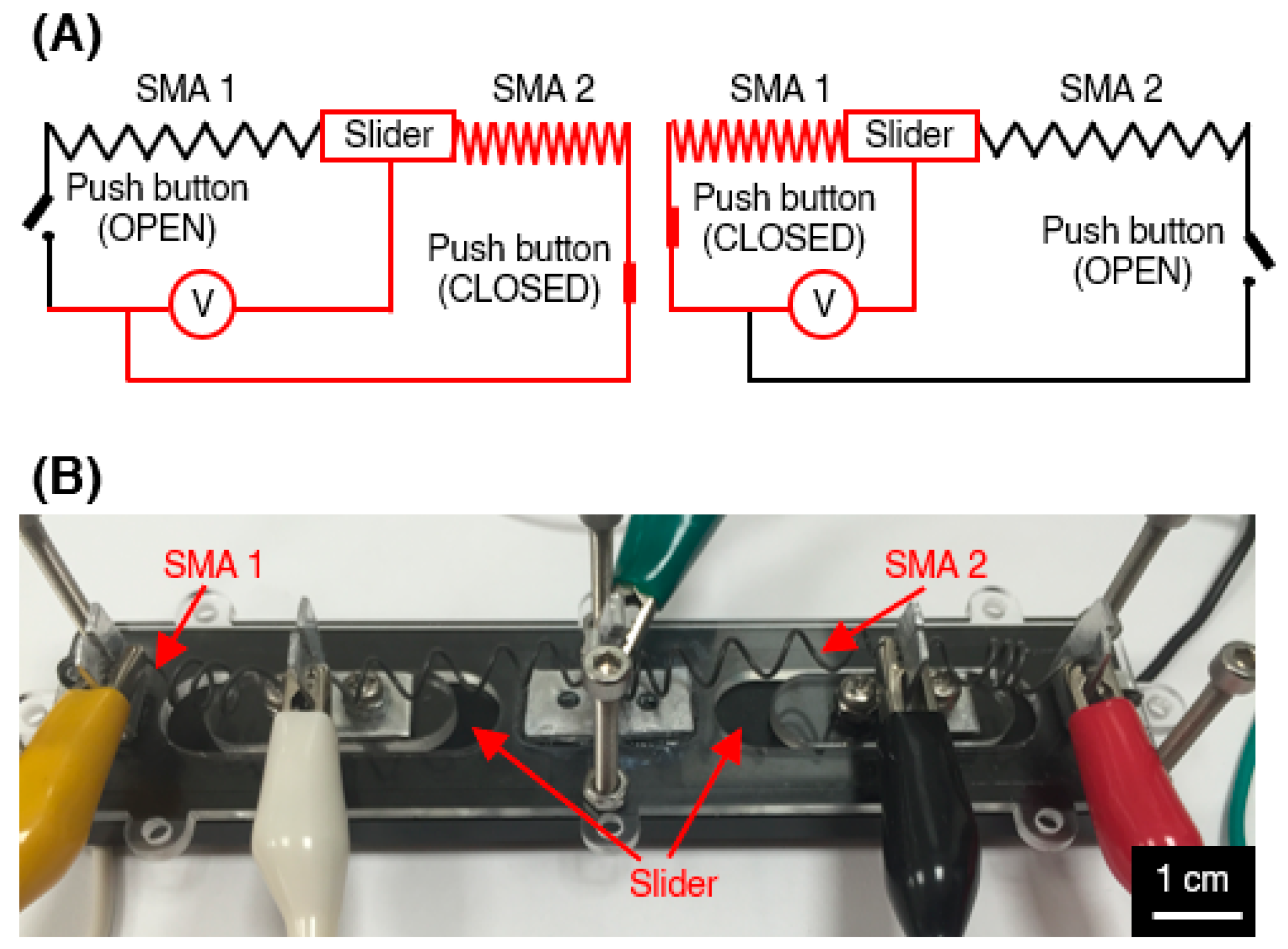
In our prototype, the activation of the SMA spring by heating to a temperature above its transition temperature was achieved by Joule heating by connecting the SMA spring to an electrical power source, as illustrated in Figure 2A. A simple 9 V battery was found to be sufficient to return the deformed SMA to its original shape. The illustration of the simple electronic circuit that can generate Joule heating to a different portion of the spring is shown in Figure 2A,B. In the illustration, the red portion of the spring indicates that the current is passing through that area and therefore, that portion of the spring is subjected to Joule heating.
2.2. Device Prototypes
Three types of device prototypes are fabricated in our work, namely the square 9-button set (Button set A, Figure 3A), the elongated 4-button set with switches (Button set B, Figure 3B), and rectangular 4-button set (Button set C, Figure 3C). Figure 3A–C show the three device prototypes that are fabricated and assembled. Each of these three device prototypes has a different design, although their working mechanisms are similar.
The top cover, buttons, and sliders used in our prototypes are made from aluminum alloy whose surface has been oxidized. These parts were fabricated by CNC machining to ensure the precision of the parts. The designs of the top cover, buttons, and sliders were made and simulated using SolidWorks (Dassault Systèmes, Vélizy-Villacoublay, France).
The top cover is the topmost element of the prototype that is cut out for the buttons to slot in. As the design of the three device prototypes used in our work varies, the design and the shape of their top cover are different from one another. The top cover for button set A has dimensions of 100 mm long, 100 mm wide, and 5 mm thick. It has 9 circular holes with a dimension of 20 mm in diameter. The top cover for button set B has a dimension of 200 mm long, a largest width of 40 mm, and 5 mm thick. In addition to the 4 square holes to slot in the buttons, two additional circular holes to fit in push button switches are also present in the top cover for button set B. Lastly, the top cover for button set C has a dimension of 140 mm long, 30 mm wide, and 5 mm thick. Similar to button set B, button set C has four holes although in this case the hole is circular in shape.
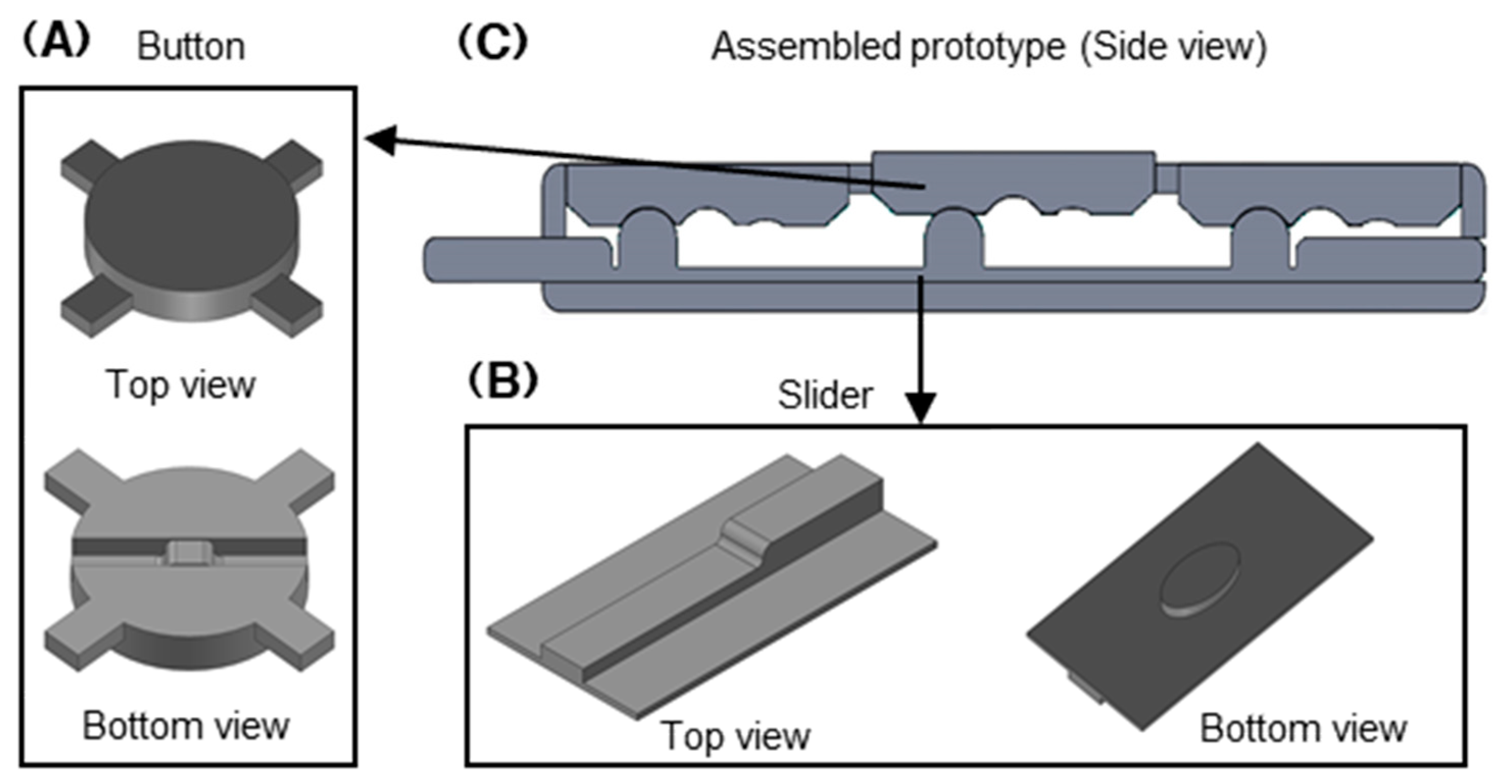
As mentioned above, the three button sets use the different shape and size of the buttons as button set A and C use circular buttons, whereas button set B uses square buttons. Both the circular and square buttons are designed to have a flat top surface, but have protrusions and profiles on the bottom to accommodate the slider’s movement and the rising and falling action of buttons. Figure 4A shows the top and bottom view of the circular button. The square button has a similar profile to the circular button as they only differ in size and shape.
The slider is the movable part that controls the rise and fall of the buttons. All three button sets have different slider designs as the three button sets have different button patterns. Even though the design of the sliders for the button set varies, one of the surfaces of all the sliders have protrusions and profiles that allow the buttons to rise and fall depending on the button patterns of the set. The other side of the slider is a flat surface on which a small elliptical piece is attached to control the sliding orientation and the direction of the slider, as shown in Figure 4B; whereas Figure 4C shows the side view of the overall assembly of the top cover, buttons, and the sliders. The design profile and protrusions on the buttons and the sliders that facilitate the locking mechanism of the patterns and positions of the buttons can be clearly seen in Figure 4C.
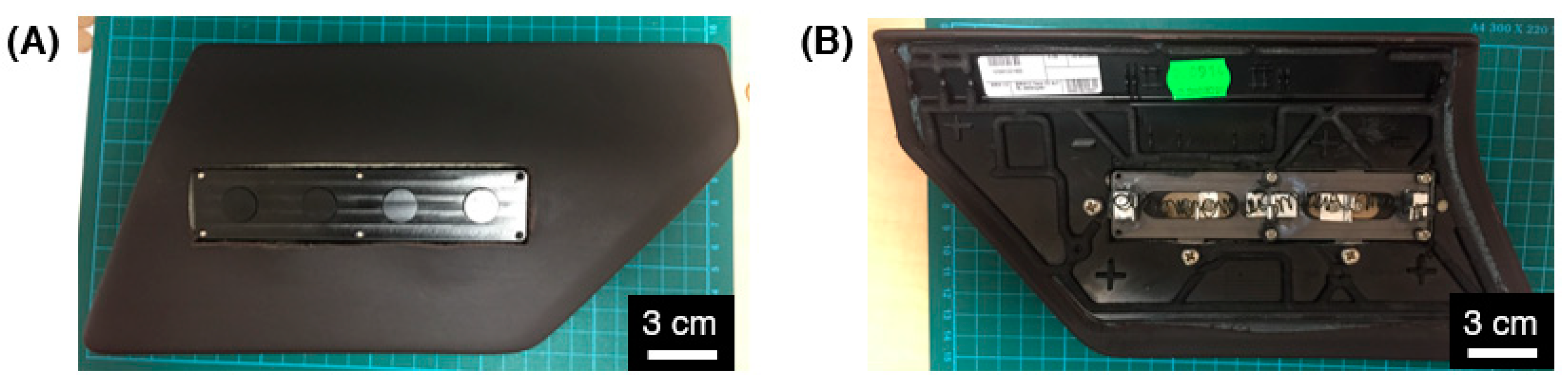
Similarly, the bottom covers of the three button sets vary in size and shape, but all of them are made from the laser cutting of PMMA. The bottom covers have a varying number of holes along the edges that are used to slot in the screws and nuts to hold and tighten all the components together. In the middle of the bottom cover, there are cut out spaces to fit in the small elliptical piece protruding from one of the surface of the slider. This cut out space is used to control the sliding orientation and alignment and also limit the sliding distance. After the top cover, buttons, sliders, and bottom cover have been put together, the prototype is slot into a plastic case that has been cut out to slot in the device prototypes, as shown in Figure 5A,B. This plastic case is an original part of one of vehicle that will be used for demonstration purposes.
Prototype devices with other shapes and button configurations have also been fabricated and tested, such as the device prototype with 9 circular buttons and 3 button activation patterns and a device prototype with a similar size and shape to the device described above but with rectangular buttons. However, we focused on using the above device set for the demonstration with the user interface.
2.3. Color Change Visual Enhancement Materials
Various color change materials can be laid on top of the top surface of the device prototype to enhance the visual appearance and distinction of the active buttons from the inactive ones. These color change materials belong to a class of mechanochromic materials, which are materials that undergo color change when the mechanical load is applied on it [17,18]. The rise of the buttons when they are activated exerts a localized mechanical load on the color change materials and therefore, causing some or all parts of the material directly on top of the active buttons to change its color or form a distinguishing contour of the active buttons. Consequently, the active and inactive buttons can also be visually distinguished as they have different colors.
Several color change materials have been explored and tested in this work, such as the standard elastic cloth, pristine and modified holographic film (Figure 6A), sublimation printed elastic cloth (Figure 6B,C), and elastomer-based transparency film (Figure 6D). Apart from the elastomer-based transparency film, the remaining color change materials are commercially purchased from various sources.
3. Working Mechanism of Buttons on Demand
The working mechanism of the buttons on demand device discussed in this paper is through the combination of smart mechanical design and smart materials. The smart mechanical design defines the patterns of the buttons when activated and also locks the position of the buttons according to the defined pattern. On the other hand, the smart material used in the device triggers the activation and deactivation of the buttons by controlling the movement of the sliders. The movement of the slider and its corresponding activation and locking of the buttons’ position is illustrated in Figure 7A,B.
3.1. Mechanism of Two-Button and Three-Button Patterns of Buttons on Demand Device
As mentioned earlier, the components that make up the device prototype are the top cover, slider, buttons, SMA, wires, clamps, and power source to make up the electrical circuit. For both two-button and three-button patterns devices, the SMA will be clamped at three separate locations with electrical wires being attached to the three terminals, as shown in Figure 8A–C. Depending on which part of the electrical circuits are being closed, the current and therefore the corresponding Joule heating will be applied to the corresponding section of the SMA and bring about the contraction of the left or right portion of the SMA. Using Figure 8A–C as an example, closing the circuit created by the black and yellow wires will cause contraction of the left portion of the SMA and therefore cause the slider to move to the left.
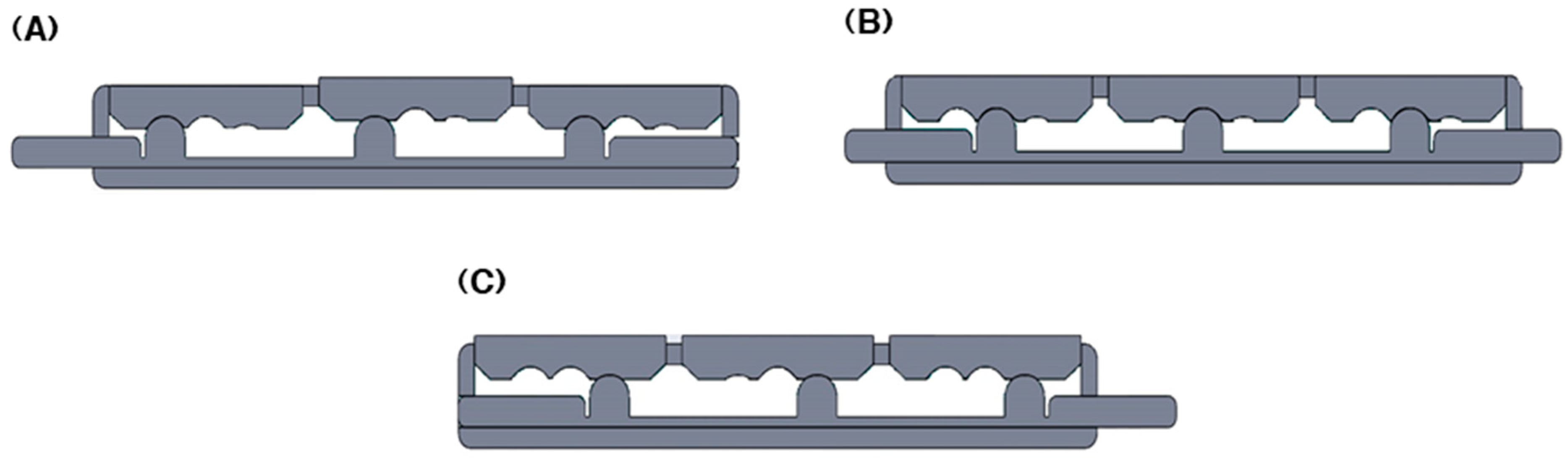
In a two-button pattern device, the position of the buttons, and therefore the activation and deactivation of the buttons, is governed by whether the slider is located at the left-most or right-most position. When it is inactive, all of the buttons will be flat, whereas when it is active, all of the buttons will protrude upwards. On the other hand, in a three-button pattern device, an additional active buttons pattern can be generated as the middle position of the slider and can be used to define an additional buttons pattern. Similarly, the left-most and right-most position will cause all of the buttons to be flat or protrude upwards. Illustration of the movement of the slider to generate three patterns of the buttons on demand device is illustrated in Figure 9A–C.
3.2. Mechanism of Button Set C
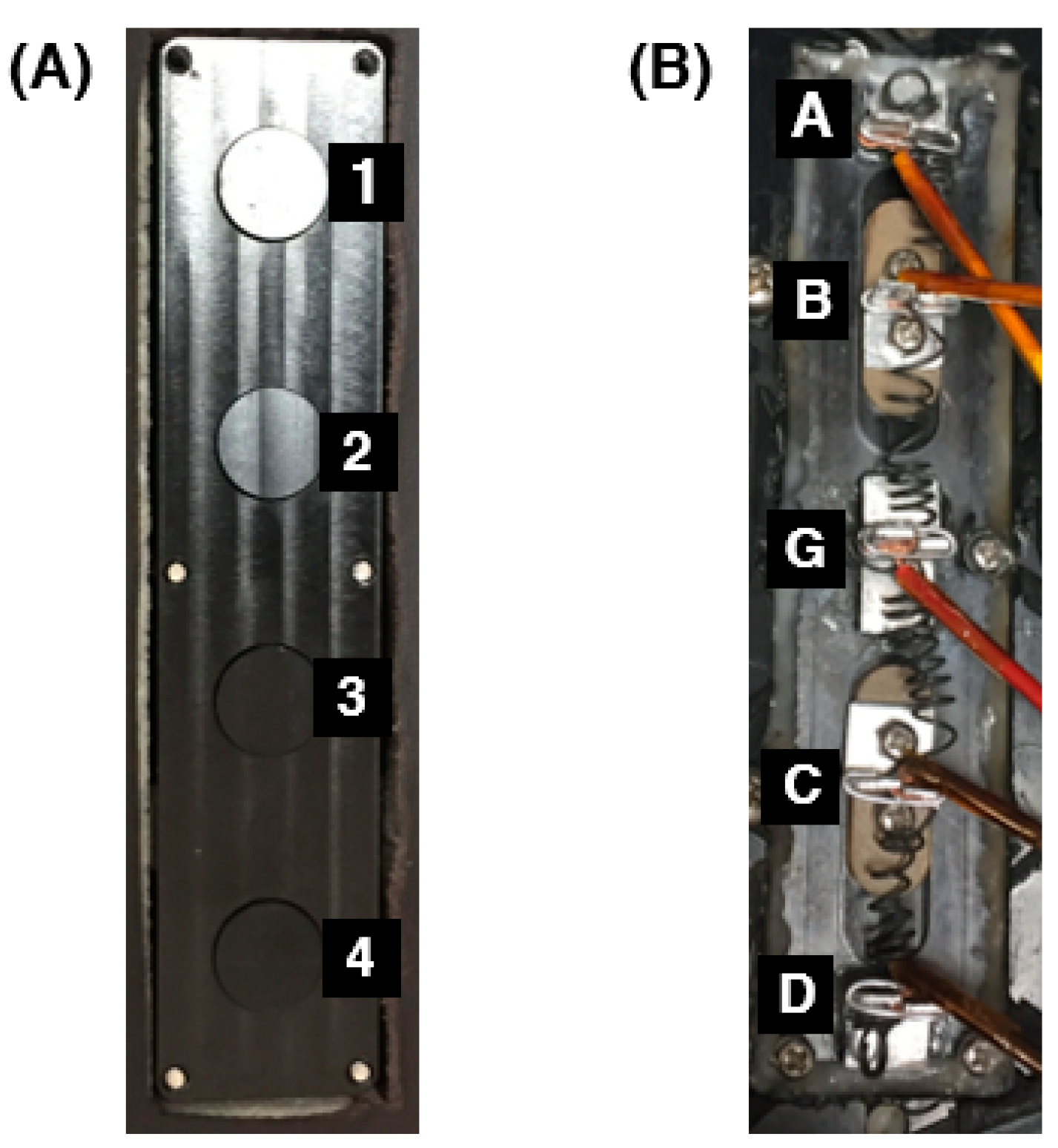
Figure 10A,B show the top and bottom appearances of the buttons on demand device prototype after it was slotted into the plastic case with the electrical wires connected at various points along the spring. In Figure 10A, the buttons are marked from top to bottom as 1, 2, 3, and 4, whereas in Figure 10B, the wires are denoted with the letters A, B, G, C, and D. There are two sliders in the above prototype: one controlling buttons 1 and 2, and the other controlling buttons 3 and 4. The two sliders and therefore, the button pairs 1–2 and 3–4, can be independently controlled by connecting the wires into separate power sources.
By referring to Figure 10A,B, the working mechanism of the buttons on demand prototype will be explained in greater detail. As mentioned above, there are two sliders installed in the above prototypes and therefore the pair of buttons can be independently controlled. Wires A, B, and G control the travel of buttons 1 and 2, whereas wires C, D, and G controls the travel of buttons 3 and 4.
When wires A and B are connected to the power source, electrical current will pass through the section of the SMA spring between wires A and B and therefore cause the Joule heating of that portion of spring. As the entire spring is in a stretched and deformed state, the Joule heating of the portion of the spring between wires A and B will cause it to shrink and therefore, pull the slider towards point A. Movement of the slider towards point A will cause buttons 1 and 2 to rise and go into active mode. The same principle and buttons activation can be said for buttons 3 and 4 when wires C and D are connected to the power source. The Joule heating of the portion of the SMA spring between C and D will cause the spring to contract and therefore pull the slider towards point D. Once the buttons have risen and are in active mode, the application of the electrical current is no longer necessary as the design profile on the bottom surface of the buttons allows their positions to be locked.
On the other hand, connecting wires B and G and C and G to the power source can cause button pairs 1–2 and 3–4, respectively, to fall, and therefore, go into inactive mode. Here, the respective slider will be pulled by the contraction of the spring towards point G. Switches, such as the simple push button switches or proximity sensor switches can be used to help control the passing of the electrical current through the various portions of the springs, and therefore, help control the activation and deactivation of the corresponding buttons.
4. Simulation and Demonstration of Buttons on Demand Device
4.1. Electrical Voltage Requirement for Activation
As mentioned above, the shape memory effect of the SMA is achieved through thermal stimulation via Joule heating. As such, a power source that is able to drive current through the SMA is required. Various kinds of power source can be used in order to trigger the shape memory effect of the SMA and therefore, cause portions of the SMA spring to contract. Upon connecting the SMA spring integrated prototype with a power source and a multimeter, we noticed that an electrical current of approximately 2.5 A is required to trigger the activation of the shape memory effect of the SMA.
One of the power sources that were used in our work was the commercial Alkaline 9 V battery. From our test and simulations, we observed that this battery was able to drive sufficient current into the SMA spring to generate the heat necessary for the activation of the SMA spring, which has a shape memory activation temperature of 60–65 °C. The advantage of using this battery is that it is commercially available, cheap, and easy to use. However, one of the drawbacks of using this particular battery is the relatively longer time taken to heat up the SMA spring to its activation temperature. When the Alkaline 9 V battery is used as the power source, the contraction of the SMA spring is achieved after approximately 10 s. For vehicle buttons’ application, the activation period of 10 s may be too long.
To accelerate the activation of the SMA spring, other types of battery can be used, such as the lead-acid rechargeable battery. The lead-acid battery that we tested was 12 V, 2000 mAh battery. When this battery was used as the power source, the activation of the SMA spring can be achieved instantaneously, i.e., within 1–2 s. However, the drawback of using this battery is that as it is a more powerful battery than the Alkaline 9 V battery, the current discharge may be excessively large. As a consequence of the large current discharge, the battery may heat up the SMA spring to a very high temperature, which causes the deformed and elongated shape of the SMA spring to be permanent. Once the deformation of the SMA spring has become permanent, connecting that particular portion of the SMA spring to a power source may not be able to bring about the contraction and recovery of the spring. In addition, the very high temperature of the spring upon connecting the SMA spring to the power source may also burn other components of the prototypes.
From the various types of battery that have been used in our test, the best battery that is able to deliver the relatively quick activation of the SMA, safe to use without potentially causing any burning and permanent deformation of the spring, compact, and easy to use is the Lithium rechargeable 18,650 battery. The 18,650 Lithium battery that was used in our test has an electrical voltage of 3.7 V and an electrical discharge of 2200 mAh. When the 18,650 lithium battery was used as the power source for the buttons on demand prototype, the activation of the SMA spring can be achieved within 3–4 s, which is acceptable for vehicle buttons’ application. In addition, this battery is not capable to heat the SMA spring to an excessively high temperature that may cause the burning of the components surrounding the spring and its permanent deformation.
It is important to note, however, that at this current stage, regardless of the type of battery that is used as the power source to trigger the Joule heating of the SMA spring, the cooling down period of approximately 10–15 s is necessary after every activation cycle of the SMA spring. In order to obtain an optimum contraction of different portions of the SMA spring, it is best to allow the SMA spring to cool down to approximately 35 °C before the next activation cycle is triggered. In the future, we hope to shorten the cooling down period by means of integrating a cooling system into the prototype.
4.2. In-Car Demonstration with User Interface
After the assembly of the buttons on demand prototype set C and building the electronic circuit, the device prototype was mounted and fixed onto a plastic frame case that was cut out in the middle. As the plastic frame was an original part of the vehicle, the mounting and dismounting of the case to and from the vehicle was relatively easy. A force sensor was fixed on top of each circular button so that the touching of each button will allow input command to be independently delivered into the user interface. A user interface simulation that resembles the user interface used in current vehicle was used for the in-car demonstration. For the demonstration, the user interface simulation was installed in a tablet PC and it was connected to the device prototype using an Arduino USB driver. Figure 11 shows the appearance of the interior of the car after the installation of the buttons on demand device set together with placing the tablet PC to control the simulation.
The user interface simulation was programmed to simulate a driving scenario whereby the driver can choose interchangeably between parking mode at 0 mph, city driving mode at 50 mph, and highway driving mode at 110 mph, by means of swiping left and right at the screen of the tablet. In addition, different functions and features corresponding to different buttons’ activation have also been programmed in the simulation depending on which mode the simulation was currently in. Figure 12A–D show the snapshots of the user interface simulation in the engine’s off state, parking mode, city driving mode, and highway driving mode, while Figure 13A,B shows the appearance of the buttons on demand device set when only two buttons and all four buttons are active.
From Figure 12B–D, it can be observed that different options are available in each mode. For example, in parking mode, whereby the car is in stationary mode (0 mph), the top two selections will appear and become active while the bottom two selections will remain idle and inactive. Correspondingly, the buttons on demand device will adapt to the driving mode that the car is in and make adjustments in terms of the activation and inactivation of the buttons. As such, when the car is in parking mode, the top two buttons will rise and become active while the bottom two buttons will remain flat and inactive. As soon as the corresponding buttons become active, pressing the active buttons on the buttons on demand device will allow the driver to input a command into the car and therefore perform functions that are desired by the driver. Figure 14A–C gives some examples of pressing active buttons on the device and delivering a command to the car in different modes. Similarly, when the car is in city driving mode, only the bottom two buttons will become active and when the car is in highway driving mode, all four buttons will become active. It is also important to note that when the car is in highway driving mode, the top high buttons will no longer perform the same function as when they are in the parking mode.
4.3. Visual Enhancement with Mechanochromic Material
Various mechanochromic and color change materials were laid on top of the buttons on demand sets in order to test their capabilities in terms of enhancing the visual appearance of the set and at the same time, further distinguish the active buttons from the inactive ones. As mentioned in Section 2.3 and Figure 6, some of the materials that were tested were elastic cloth, modified holographic film, sublimation printed elastic cloth, and elastomer-based transparency film.
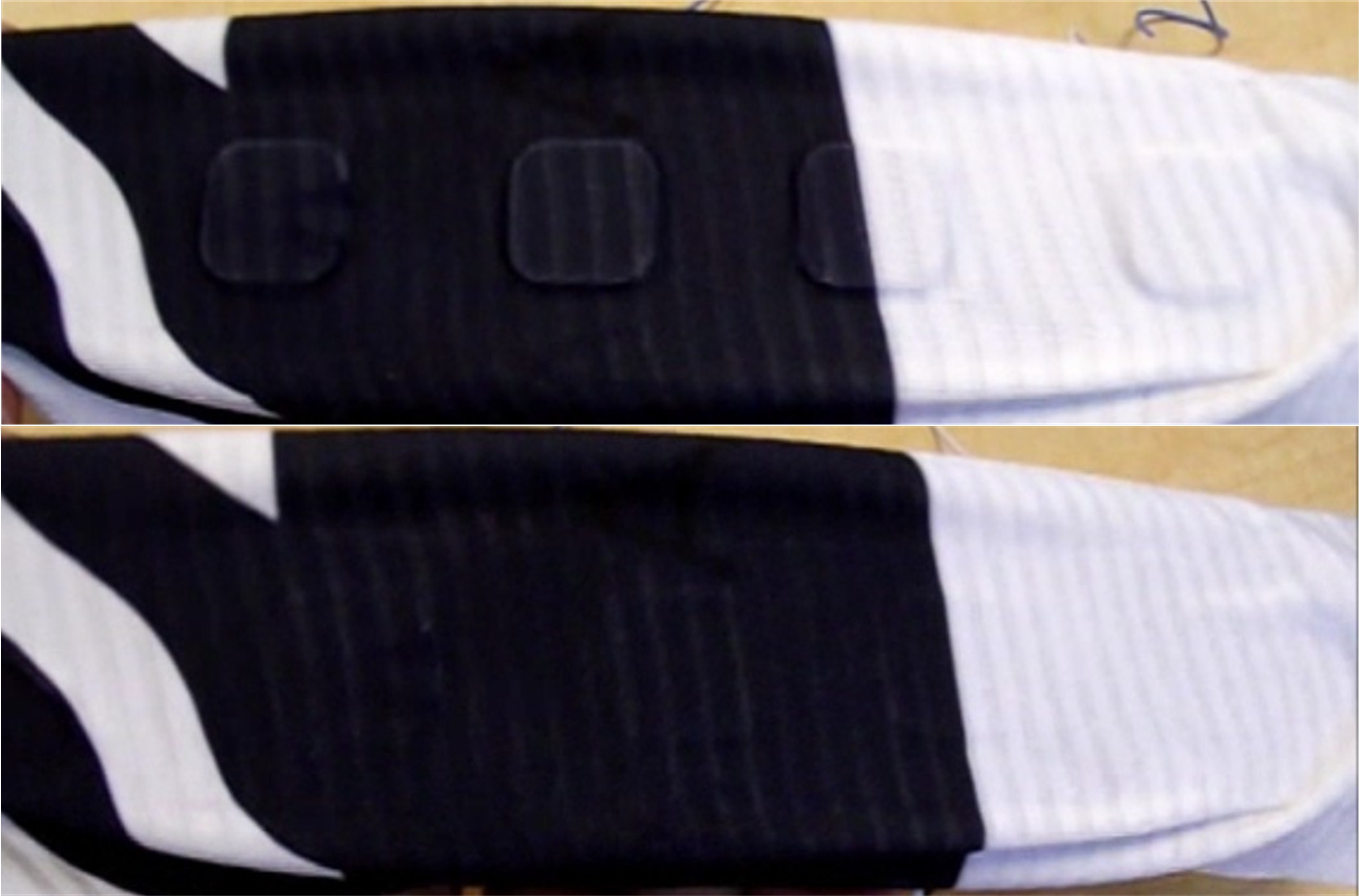
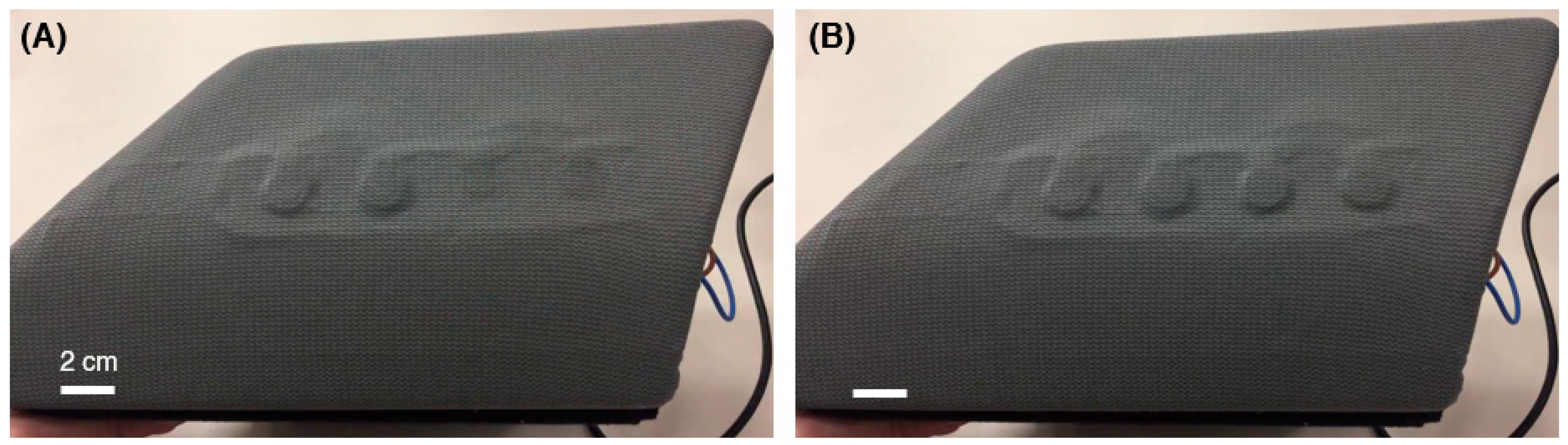
In general, all the materials tested in our work showed promising abilities in enhancing the visual appearance of the active buttons. The most promising result was provided by the sublimation printed elastic cloth. This particular cloth was relatively thin, highly stretchable, and easy to handle. Figure 15 shows the appearance of the cloth covered button set when the buttons are inactive (Figure 15A) and when the buttons are active (Figure 15B). From Figure 15A, it can be observed that when the buttons are inactive, the cloth will fully conform to the flat surface of the buttons. On the other hand, when the buttons are active (Figure 15B), due to the 1.5 mm rise of the buttons, the portion of the cloth that is directly on top of the buttons will be stretched and therefore, become lighter in color—especially along the border of the buttons. This is because the elastic cloth adheres to the top cover of the button set, but it does not adhere to the buttons. In our test, this particular cloth performs better than other elastic cloths because once the protrusions of the buttons are removed when the buttons return to inactive state, the cloth instantaneously returns to being flat, i.e., no residual stretching observed along the border of the buttons.
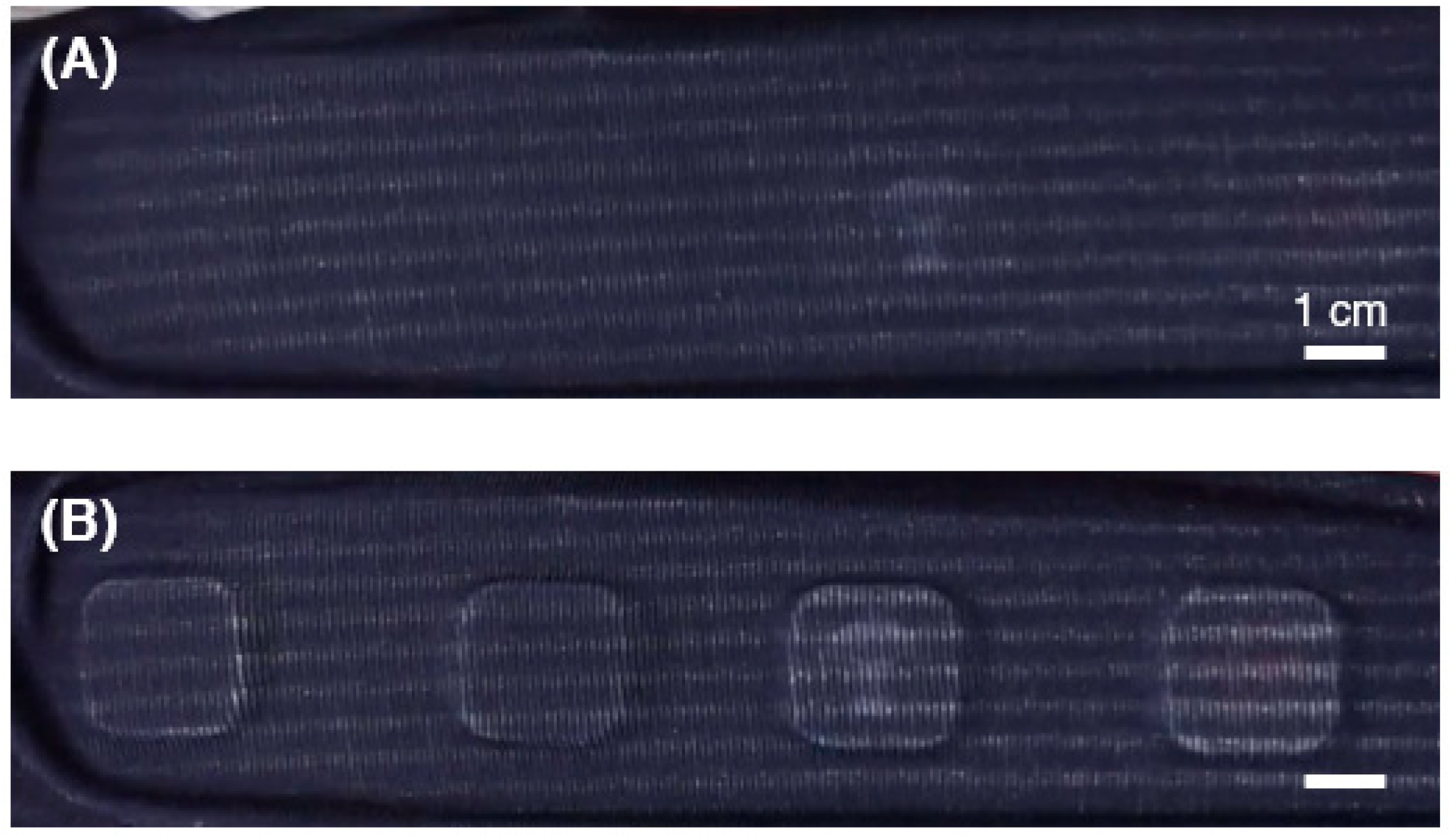
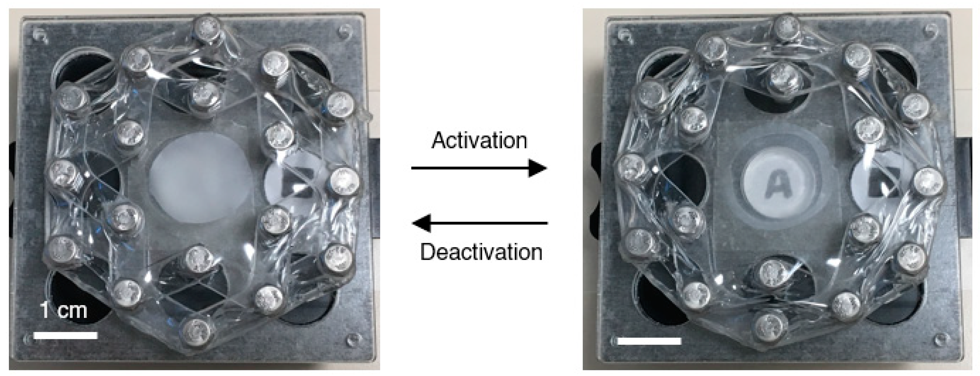
Other color change materials such as the modified holographic film and elastomer-based transparency film also showed promising abilities; however, both of them possess some limitations that need to be addressed before they can be mounted on top of the buttons on demand set. In the case of the modified holographic film, from our test, we noticed that this particular film is relatively rigid. As such, the protrusion of buttons larger than 1 mm may cause the film to break, especially along the border of the buttons. On the other hand, for the elastomer-based transparency film, which has nanometer-sized metal particles being sputtered on top of the elastomer film, some design parameters need to be addressed so that the biaxial strain applied by the protrusion of the buttons could generate change in the transparency of the film, as illustrated in Figure 16.
5. Future Works
Although the work that we performed successfully demonstrated the working concept of buttons on demand, including the successful installation and simulation of the device in the car, there are some aspects that can be addressed and improved before the device starts to be used commercially. One area that can be further improved is the insulation of the heat generated within the SMA spring so as to eliminate any safety risks of burns and fire as well as cool down the SMA spring after its activation so that the SMA spring can be repeatedly activated at ease. Furthermore, similarly to the smart surface [19], the test on the long-term lifecycle of the buttons on demand set at various ambient temperatures also needs to be conducted before this particular device can be used commercially.
In addition, other SMA materials that are relatively flat can be explored in order to reduce the overall thickness of the device set. Although the current SMA spring was working fine in our test, one of the issues that we noticed was the relatively bulky size of the SMA spring as it comes in a solenoid form. Other SMA materials that are flat and relatively pliable can be heat-treated into a flat coil shape and this can potentially significantly reduce the thickness. Early work on flat SMA coil has been performed; however, further tests, especially on its lifecycle, will be performed in the future.
6. Conclusions
In this paper, we presented a novel buttons on demand concept driven by smart materials and smart mechanical design. Here, the buttons will protrude and appear when activated and remain flat and concealed when inactive. As a result, the possibilities of wrong input by the driver can be minimized, enabling the driver to maintain their attention on the road while driving. In our work, we made several device prototypes using relatively inexpensive materials, such as oxidized aluminum, PMMA cover, and Ni–Ti shape memory alloy, and successfully integrated and simulated its working principle together with the user interface simulation in the car. Since the smart mechanical design enables the patterns and positions of the buttons to be locked, only a short application of electrical current is required as the power source from the off-the-shelf batteries. We also successfully covered the button set with elastic cloth, which improves the visual appearance of the set in addition to distinguishing the active buttons from the inactive ones.
Author Contributions
Conceptualization, M.S.K., G.K.L. and W.M.H.; data curation, C.R.; formal analysis, H.M.C.; funding acquisition, W.M.H.; investigation, C.R., M.S.K., H.M.C. and W.M.H.; methodology, M.S.K. and G.K.L.; project administration, W.M.H.; supervision, W.M.H.; visualization, M.S.K.; writing—original draft, C.R.; writing—review and editing, M.S.K. and W.M.H. All authors have read and agreed to the published version of the manuscript.
Funding
This project was supported by BMW-NTU Joint R&D program and AcRF Tier 1 (RG172/15), Singapore.
Institutional Review Board Statement
Not applicable.
Informed Consent Statement
Not applicable.
Data Availability Statement
The authors exclude this statement.
Acknowledgments
We thank Michael Haller and Christian Rendl from the Media Interaction Lab of University of Applied Sciences Upper Austria (Hagenberg, Austria) for constructive discussions and help.
Conflicts of Interest
The authors declare no conflict of interest.
References
- Sousanis, J. World Vehicle Population Tops 1 Billion Units. Available online: http://wardsauto.com/news-analysis/world-vehicle-population-tops-1-billion-units (accessed on 22 November 2016).
- Tencer, D. Number Of Cars Worldwide Surpasses 1 Billion; Can The World Handle This Many Wheels? Available online: http://www.huffingtonpost.ca/2011/08/23/car-population_n_934291.html (accessed on 22 November 2016).
- MobileBurn.com. What Is Haptic Feedback? Available online: http://www.mobileburn.com/definition.jsp?term=haptic+feedback (accessed on 22 November 2016).
- Sallnas, E.-L.; Rassmus-Grohn, K.; Sjostrom, C. Supporting Presence in Collaborative Environments by Haptic Force Feedback. ACM Trans. Comput.-Hum. Interact. (TOCHI) 2000, 7, 461–476. [Google Scholar] [CrossRef]
- Garzon, S.R.; Poguntke, M. The Personal Adaptive In-Car HMI: Integration of External Applications for Personalized Use. In UMAP 2011: Advances in User Modelling; Ardissono, L., Kuflik, T., Eds.; Springer: Berlin/Heidelberg, Germany, 2012; Volume 7138, pp. 35–46. [Google Scholar]
- Jolda, M.; McClain, M.; Rudolph, A.; Henze, S.; Toggweiler, J. Sliding Hard Keys. U.S. Patent 13852579, 28 March 2013. [Google Scholar]
- Tactus A New Dimension of Touch; Tactus Technology: Fremont, CA, USA, 2012.
- Savioz, G. Multi-Finger Haptic Devices Integrating Miniature Short-Stroke Actuators. Ph.D. Thesis, École Polytechnique Fédérale de Lausanne, Lausanne, Switzerland, 2012. [Google Scholar]
- Kalairaj, M.S.; Huang, W.M. Shape memory actuated sliding mechanism for rapid switching between button-patterns for adapted human-machine interaction at different automatization levels in automobiles. In MATEC Web of Conferences; EDP Sciences: Les Ulis, France, 2017; Volume 90, p. 01010. [Google Scholar]
- Kalairaj, M.S.; Huang, W.M.; Klanner, F. Buttons on Demand Using Sliding Mechanism. In Proceedings of the International Conference on Electrical Engineering and Automation (EEA2016), Hong Kong, China, 24–26 June 2016; pp. 996–1004. [Google Scholar]
- Konfigurierbare Eingabe-Vorrichtung (Configurable Input Device). DE102016215828A1, 23 August 2016.
- Jani, J.M.; Leary, M.; Subic, A.; Gibson, M.A. A Review of Shape Memory Alloy Research, Applications, and Opportunities. Mater. Des. 2014, 56, 1078–1113. [Google Scholar] [CrossRef]
- Huang, W.M.; Sun, L.; Ding, Z.; Zhao, Y.; Wang, C.C.; Purnawali, H.; Tang, C. Stimulus-responsive Shape Memory Materials: A Review. Mater. Des. 2012, 33, 577–640. [Google Scholar]
- Huang, W.M.; Ding, Z.; Wang, C.C.; Wei, J.; Zhao, Y.; Purnawali, H. Shape Memory Materials. Mater. Today 2010, 13, 54–61. [Google Scholar] [CrossRef]
- Wang, C.C.; Huang, W.M.; Ding, Z.; Zhao, Y.; Purnawali, H.; Zheng, L.; Fan, H.; He, C.B. Rubber-like shape memory polymeric materials with repeatable thermal-assisted healing function. Smart Mater. Struct. 2012, 21, 115010. [Google Scholar] [CrossRef]
- Lei, M.; Xu, B.; Pei, Y.; Lu, H.; Fu, Y.Q. Micro-mechanics of nanostructured carbon/shape memory polymer hybrid thin film. Soft Matter 2016, 12, 106–114. [Google Scholar] [CrossRef] [PubMed] [Green Version]
- Weder, C. Mechanochromic Polymers. In Encyclopedia of Polymeric Nanomaterials; Kobayashi, S., Mullen, K., Eds.; Springer: Berlin/Heidelberg, Germany, 2015; pp. 1–11. [Google Scholar]
- Peterson, G.I.; Larsen, M.B.; Ganter, M.A.; Storti, D.W.; Boydston, A.J. 3D-Printed Mechanochromic Materials. ACS Appl. Mater. Interfaces 2015, 7, 577–583. [Google Scholar] [CrossRef] [PubMed]
- Smart Surface. Continental AG. Available online: https://conti-engineering.com/components/smart-surface/ (accessed on 30 June 2018).
Figure 1.
(A) Original shape of SMA spring. (B) Shape of SMA spring after deformation.
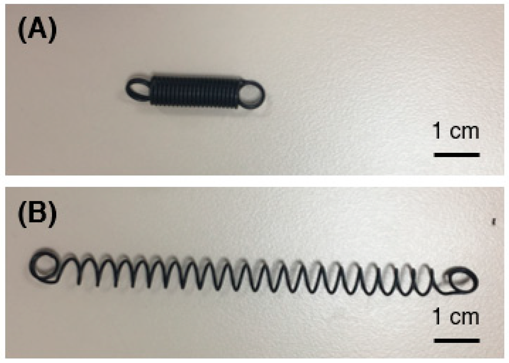
Figure 2.
(A) Electronic circuits to trigger the contraction of the specific portion of SMA spring. (B) Connection of electric wires to different parts of SMA spring.
Figure 2.
(A) Electronic circuits to trigger the contraction of the specific portion of SMA spring. (B) Connection of electric wires to different parts of SMA spring.

Figure 3.
Prototypes of (A) button set A (top surface: 10 cm × 10 cm); (B) buttons set B (top surface: ≈ 20 cm × 3 cm); and (C) button set C (top surface: 14 cm × 3 cm).
Figure 3.
Prototypes of (A) button set A (top surface: 10 cm × 10 cm); (B) buttons set B (top surface: ≈ 20 cm × 3 cm); and (C) button set C (top surface: 14 cm × 3 cm).
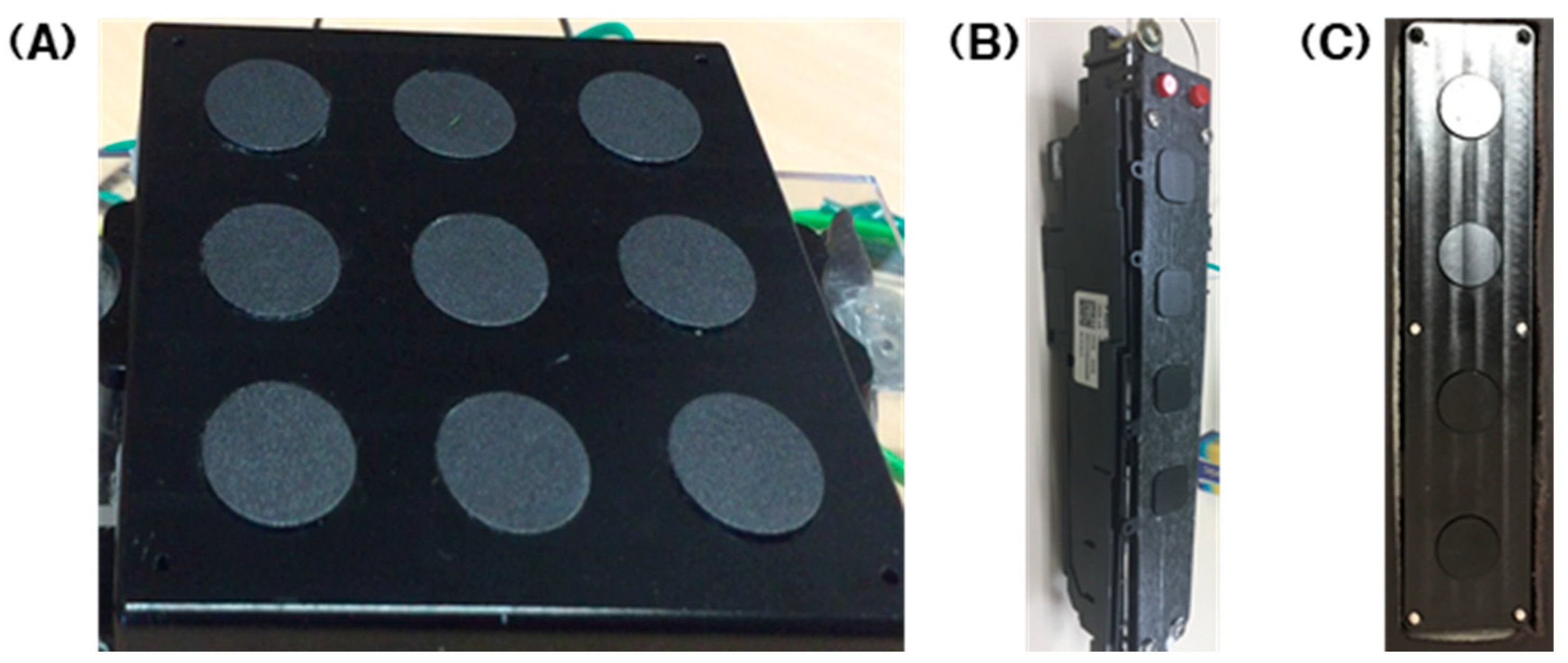
Figure 4.
(A) Top and bottom view of the circular button. (B) Top and bottom of the slider. (C) Side view of assembled prototype.
Figure 4.
(A) Top and bottom view of the circular button. (B) Top and bottom of the slider. (C) Side view of assembled prototype.

Figure 5.
Final appearances of the device prototype: (A) top view and (B) bottom view. The embedded is Button set C as shown in Figure 3C.
Figure 5.
Final appearances of the device prototype: (A) top view and (B) bottom view. The embedded is Button set C as shown in Figure 3C.

Figure 6.
(A) Modified holographic film (button set A; top surface: 10 cm × 10 cm); (B) (button set A; top surface: 10 cm × 10 cm); and (C) sublimation printed elastic cloth (button set B; top surface: ≈ 20 cm × 3 cm); (D) elastomer-based transparency film (button set A; top surface: 10 cm × 10 cm).
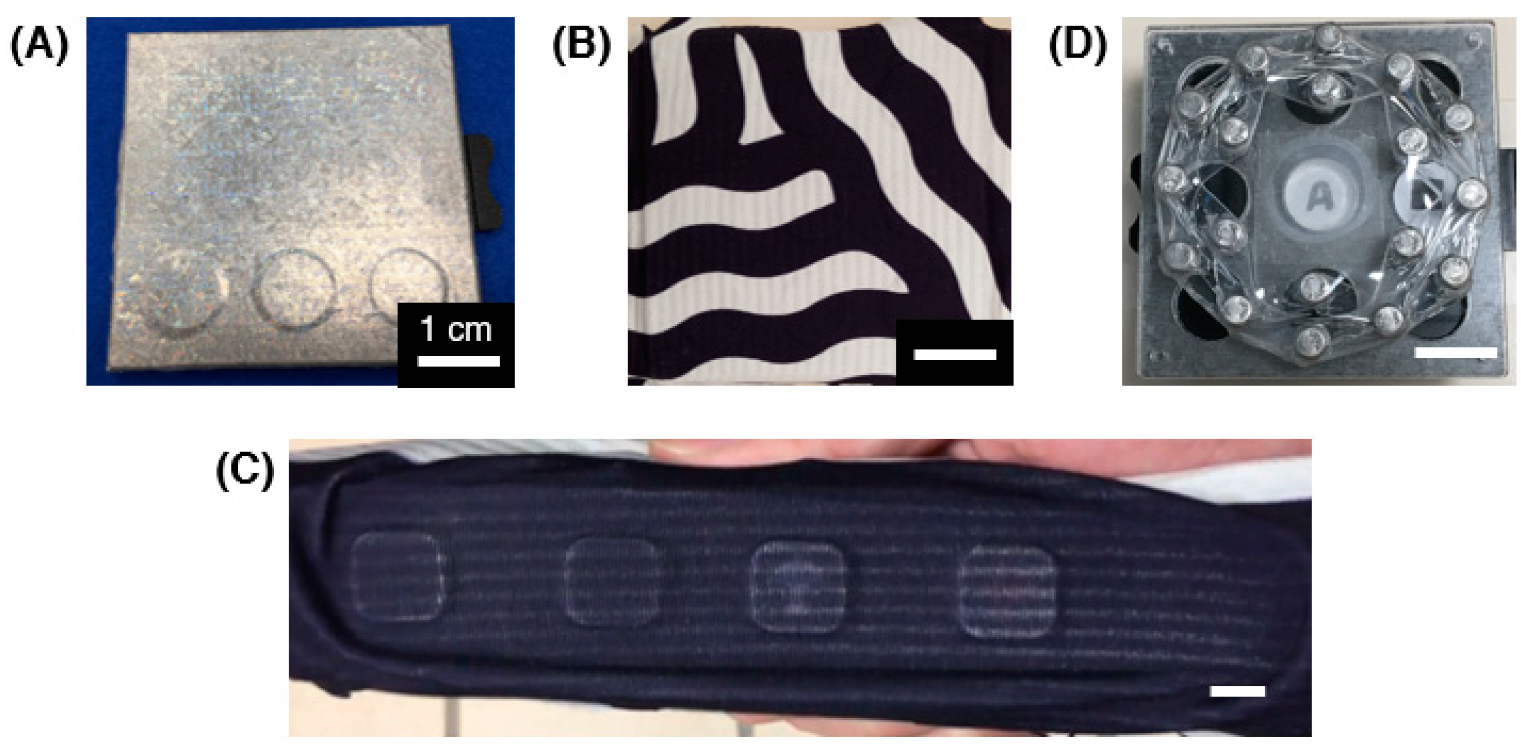
Figure 7.
Activation (protrusion, 1.5 mm) of the buttons achieved through the movement of the slider driven by the smart material. Final appearances of the device prototype: (A) top view and (B) bottom view.
Figure 7.
Activation (protrusion, 1.5 mm) of the buttons achieved through the movement of the slider driven by the smart material. Final appearances of the device prototype: (A) top view and (B) bottom view.
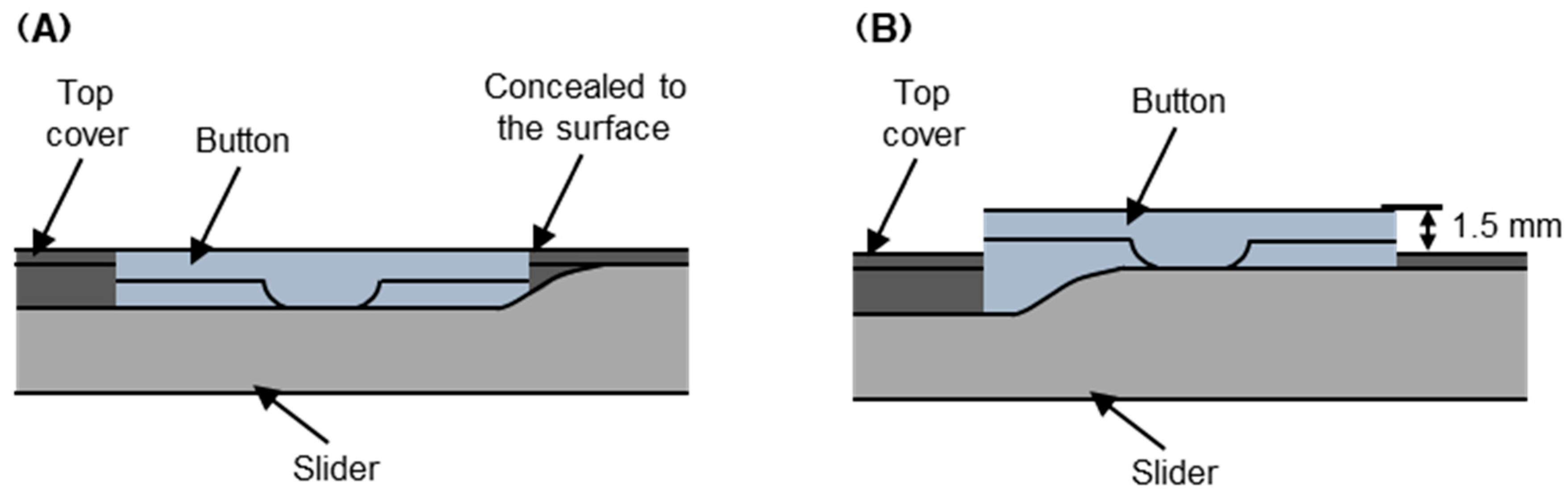
Figure 8.
Movement of the slider due to the contraction of a portion of the SMA (button set A; top surface: 10 cm × 10 cm); (A) slider at the left-most position; and (B) slider in the middle, and (C) slider at the right-most position.
Figure 8.
Movement of the slider due to the contraction of a portion of the SMA (button set A; top surface: 10 cm × 10 cm); (A) slider at the left-most position; and (B) slider in the middle, and (C) slider at the right-most position.
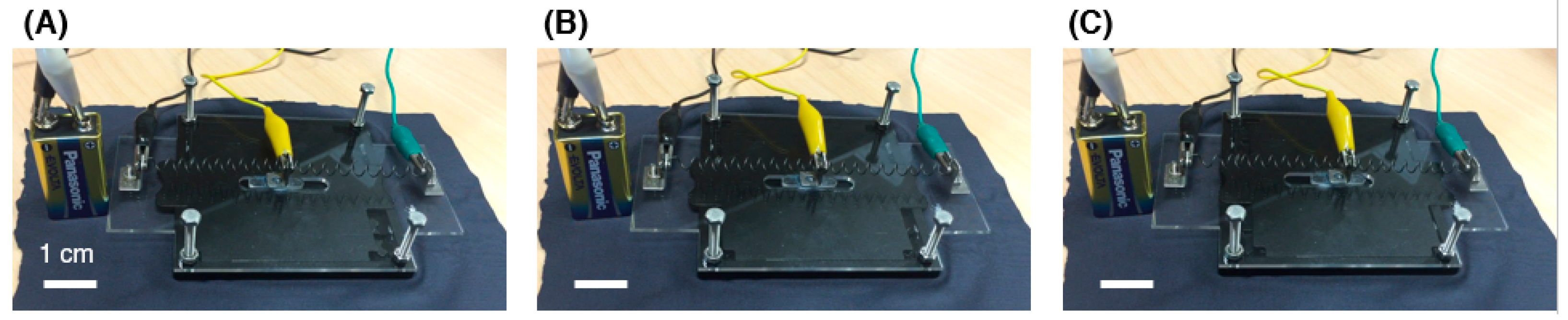
Figure 9.
Illustration of the generation of 3 patterns on the buttons on demand set: (A) pattern 1; (B) pattern 2; and (C) pattern 3.
Figure 9.
Illustration of the generation of 3 patterns on the buttons on demand set: (A) pattern 1; (B) pattern 2; and (C) pattern 3.

Figure 10.
(A) Top and (B) bottom appearances of the buttons on demand set C (refer to Figure 3C) with wire connections.
Figure 10.
(A) Top and (B) bottom appearances of the buttons on demand set C (refer to Figure 3C) with wire connections.

Figure 11.
Appearance of a car’s interior with the buttons on demand device (refer to Figure 5) being installed inside the car.
Figure 11.
Appearance of a car’s interior with the buttons on demand device (refer to Figure 5) being installed inside the car.
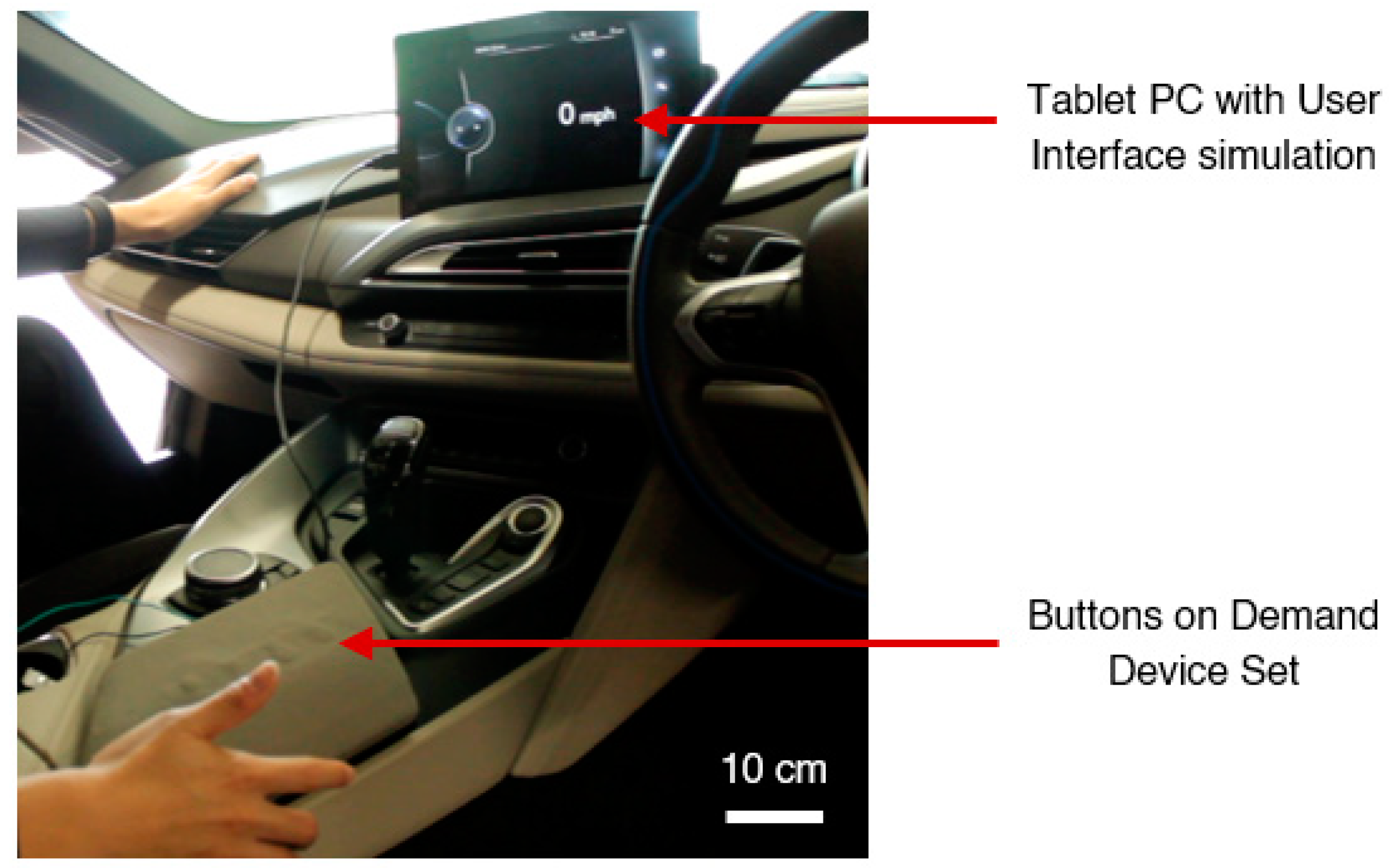
Figure 12.
Snapshots of the user interface simulation at the (A) off state; (B) parking mode; (C) city driving mode; and (D) highway driving mode.
Figure 12.
Snapshots of the user interface simulation at the (A) off state; (B) parking mode; (C) city driving mode; and (D) highway driving mode.
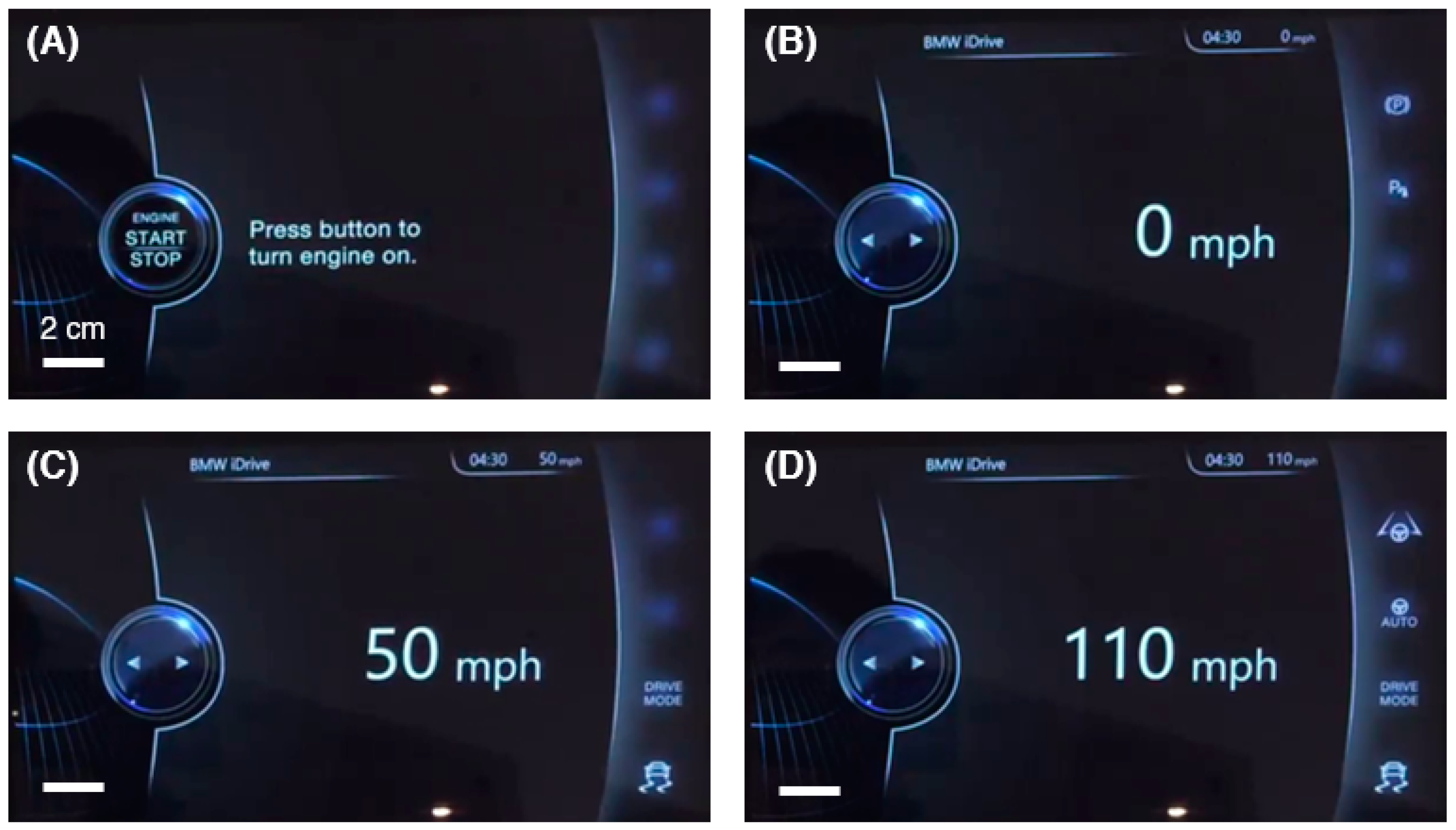
Figure 13.
Appearances of the buttons on demand device set (refer to Figure 5) when (A) only 2 buttons are active and (B) all 4 buttons are active.
Figure 13.
Appearances of the buttons on demand device set (refer to Figure 5) when (A) only 2 buttons are active and (B) all 4 buttons are active.

Figure 14.
Pressing activated buttons on the buttons on demand device (refer to Figure 5) to perform functions in (A) parking mode; (B) city driving mode; and (C) highway driving mode.
Figure 14.
Pressing activated buttons on the buttons on demand device (refer to Figure 5) to perform functions in (A) parking mode; (B) city driving mode; and (C) highway driving mode.
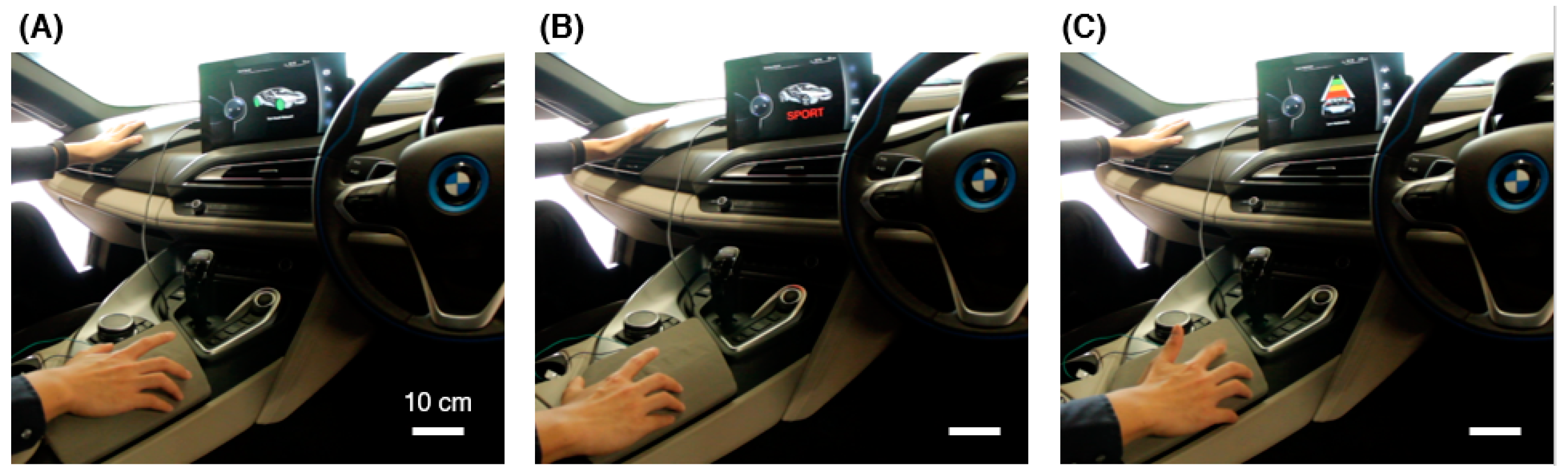
Figure 15.
Sublimation printed elastic cloth covered button set, (A) when buttons are inactive and (B) when buttons are active.
Figure 15.
Sublimation printed elastic cloth covered button set, (A) when buttons are inactive and (B) when buttons are active.

Figure 16.
Change in transparency of elastomer-based transparency film resulting in visual clarity of symbol underneath.
Figure 16.
Change in transparency of elastomer-based transparency film resulting in visual clarity of symbol underneath.

Publisher’s Note: MDPI stays neutral with regard to jurisdictional claims in published maps and institutional affiliations. |
© 2021 by the authors. Licensee MDPI, Basel, Switzerland. This article is an open access article distributed under the terms and conditions of the Creative Commons Attribution (CC BY) license (https://creativecommons.org/licenses/by/4.0/).
Share and Cite
MDPI and ACS Style
Renata, C.; Kalairaj, M.S.; Chen, H.M.; Lau, G.K.; Huang, W.M. Buttons on Demand Sliding Mechanism Driven by Smart Materials and Mechanical Design. Actuators 2021, 10, 251. https://doi.org/10.3390/act10100251
AMA Style
Renata C, Kalairaj MS, Chen HM, Lau GK, Huang WM. Buttons on Demand Sliding Mechanism Driven by Smart Materials and Mechanical Design. Actuators. 2021; 10(10):251. https://doi.org/10.3390/act10100251
Chicago/Turabian StyleRenata, Christianto, Manivannan Sivaperuman Kalairaj, Hong Mei Chen, Gih Keong Lau, and Wei Min Huang. 2021. "Buttons on Demand Sliding Mechanism Driven by Smart Materials and Mechanical Design" Actuators 10, no. 10: 251. https://doi.org/10.3390/act10100251
Note that from the first issue of 2016, this journal uses article numbers instead of page numbers. See further details here.