A Boom Energy Regeneration System of Hybrid Hydraulic Excavator Using Energy Conversion Components


1
School of Mechanical Engineering, University of Ulsan, 93, Deahak-ro, Nam-gu, Ulsan 44610, Korea
2
Department of Mechatronics, Ho Chi Minh City University of Technology and Education, Ho Chi Minh City 700000, Vietnam
*
Author to whom correspondence should be addressed.
Actuators 2021, 10(1), 1; https://doi.org/10.3390/act10010001
Submission received: 7 November 2020
/
Revised: 6 December 2020
/
Accepted: 19 December 2020
/
Published: 22 December 2020
(This article belongs to the Special Issue Advanced Fluid Power Systems and Actuators)
Abstract
:In this paper, a novel design of an energy regeneration system was proposed for recovering as well as reusing potential energy in a boom cylinder. The proposed system included a hydraulic pump/motor and an electrical motor/generator. When the boom moved down, the energy regeneration components converted the hydraulic energy to electrical energy and stored in a battery. Then, the regenerated energy was reused at subsequent cycles. In addition, an energy management strategy has been designed based on discrete time-optimal control to guarantee position tracking performance and ensure component safety during the operation. To verify the effectiveness of the proposed system, a co-simulation (using MATLAB and AMESim) was carried out. Through the simulation results, the maximum energy regeneration efficiency could achieve up to 44%. Besides, the velocity and position of the boom cylinder achieved good performance with the proposed control strategy.
1. Introduction
Hydraulic excavators are indispensable equipment in the field of construction due to the many tasks that it does such as the transportation of heavy objects, dig, and demolition. However, it is also machinery that consumes a lot of energy and emits toxic emissions into the environment [1,2,3,4,5,6,7,8]. Therefore, the problems of recovering energy as well as reducing energy consumption in an excavator are necessary, especially in boom systems where 51% of the potential energy is stored [9].
There are many boom energy recovery systems (ERSs) that have been proposed which could be divided into 3 main types: hydraulic ERSs, mechanical ERSs and electrical ERSs [10,11,12]. The hydraulic ERSs use a hydraulic accumulator to store the energy and reuse it via some auxiliary devices such as hydraulic pump or motor. The advantages of hydraulic ERSs are high efficiency and low power consumption. Shen et al. [13] used a Common Pressure Rail (CPR) which integrated a hydraulic transformer connect two-port of cylinder to analyze the influences of different control methods on a hybrid hydraulic excavator. The fuel consumption could be reduced using dynamic programming (DP), and DP also provided a standard to compare different control methods. Ge et al. [14,15] proposed a gravitational potential energy (GPE) recovery scheme with a hydraulic accumulator and an energy conversion cylinder. Their results demonstrated that under the lowering process, more than 75.9% of the GPE can be recovered into the accumulator. However, the problem of the hydraulic ERSs is that the pressure of the accumulator increases during the moving down process of the boom cylinder. Then, it hinders the velocity of the cylinder [16].
The mechanical ERSs integrate a flywheel to store the energy. The flywheel has a large inertia torque and resists changes in rotation speed. The amount of energy stored in a flywheel is proportional to the square of its rotation speed. Based on the typical characteristics of the mechanical flywheel, Jiansong Li et al. [17] proposed a new mechanical ERS integrating a flywheel, a variable hydraulic pump/motor and a regeneration flow control valve. The simulation results showed that the overall efficiency could be reached up to 62%. However, the problems of this system were the noise and mechanical friction in the couplings and gears which result in the recovery of energy being reduced over time. Therefore, mechanical ERSs have been not widely used for the boom system.
Of the three types of ERSs, the electrical ERSs are the most potential method because of their advantages such as high efficiency and low cost [18]. Yu et al. [11] used a flow control valve to regulate the flow rate through the variable displacement hydraulic motor. Hence, the torque and speed of the hydraulic motor could be kept in the high working efficiency area with variant operations. Moreover, the regeneration unit was directly placed at the output port of the boom cylinder. Therefore, the proposed system could reduce energy loss at the main control valve. The energy regeneration efficiency could be achieved by up to 57.4%. In [19], a hydraulic accumulator was installed together with a combination of hydraulic motor and electric generator at the return line of the boom cylinder. This figuration allowed that both hydraulic energy and electric energy could be harvested during the boom-down process. With the presence of an accumulator, the recovery time could be made longer. As a result, the generator worked at a constant speed; hence, working points could be deliberately distributed in high-efficiency area. The idea was then realized and validated on a real test bench [20]. An approximate 39% of total potential energy could be recovered by the proposed solution. A similar idea could be found in [21], where the combination of accumulator and motor-generator is utilized to prolong the regenerative time even when the boom lifts or stops moving. The efficiency of the proposed approach was then claimed by 58%. Another approach is considered in [22,23], where pressure compensator is integrated with a hydraulic motor and an electric generator. This setting enables both functions of pressure compensation and hydraulic energy regeneration at the same time. Nonetheless, these papers only offered solutions to the problems of potential energy recovery regardless of how to make use of the regenerated energy. Finding methods to utilize the recovered energy is also an important task and worthy of consideration.
Based on the above analysis, this paper proposes an ERS which can not only recover and but also reuse the energy in the boom cylinder system. In order to operate these functions, the proposed system includes a combination of two hydraulic and electrical devices with pump/motor and motor/generator functions, respectively. During the boom down process, the potential energy in the boom cylinder is converted into electrical energy and stored in the battery through the energy conversion components of which the electric motor/generator works in the generator mode and is driven by the hydraulic motor/pump working in the motor mode. During the boom up process, the power of cylinder is supplied from the main pump or the stored energy in the battery through the energy conversion components, which the electric motor/generator works in the motor mode, and drive the hydraulic motor/pump working in the pump mode. With the proposed structure, the ERS system can work in three operation modes: normal mode (power is supplied from the main pump), energy regeneration mode (potential energy is regenerated and stored in the battery) and energy reuse mode (stored energy in the battery is reused through the energy conversion components). Besides, an energy management strategy which used two discrete-time optimal controls (DTOC) is designed based on the state of charge of battery and load condition to operate the proposed system safety and accuracy. To demonstrate the effectiveness of the proposed system, a co-simulation model using AMESim and MATLAB was built. Several simulations were conducted with the different working modes of the system. The simulation results showed that the proposed energy management strategy reduced the chattering and the error of the cylinder displacement and the reference signal was 0.08 m. The maximum energy regeneration efficiency could reach up to 44%. In addition, the cylinder could lift up without the power from the main pump by using the stored energy from the battery, and then, the energy consumption was reduced by up to 88.74 kJ.
2. Structure and Working Principle of the Proposed System
2.1. Proposed System Structure
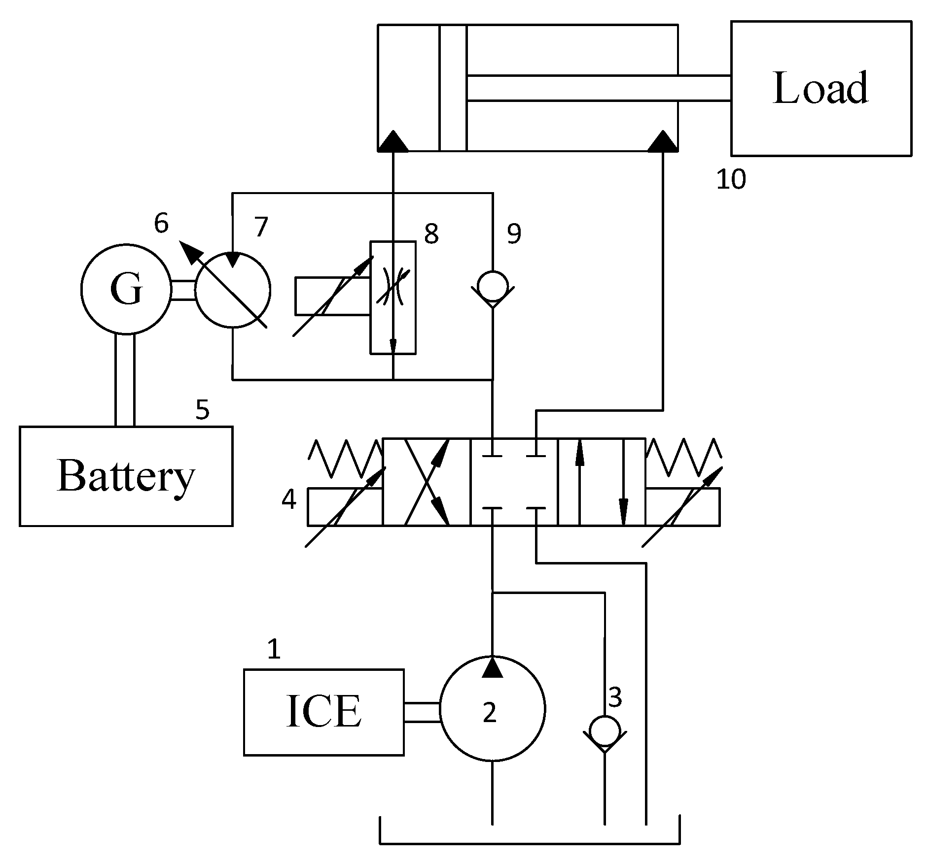
A regenerative boom system in our previous research is shown in Figure 1 [11], in which Internal Combustion Engine (ICE) 1 and hydraulic pump 2 in combination with a check valve 3 are the main hydraulic source supplying power for the system. Driven by this engine, fixed-displacement pump 2 provides hydraulic flow toward the proportional directional valve 4, whose function is to purposely control the oil direction as desired. Clearly from the circuit, an energy recovery block is presented at the piston chamber line, in which several hydraulic as well as electrical components are installed to ensure the functionality of the system. Firstly, the combination of battery-inverter 5, generator 6 and variable displacement motor 7 helps to convert hydraulic energy into electrical energy. Secondly, proportional flow control valve 8 guarantees the safety and performance of the system in case of large load and high velocity. Besides, check valve 9 at the outermost allows boom 10 to move up smoothly but blocks the opposite direction so that no energy is lost during boom-up operation while during the boom-down period, oil is forced to flow through the hydraulic motor to regenerate energy.
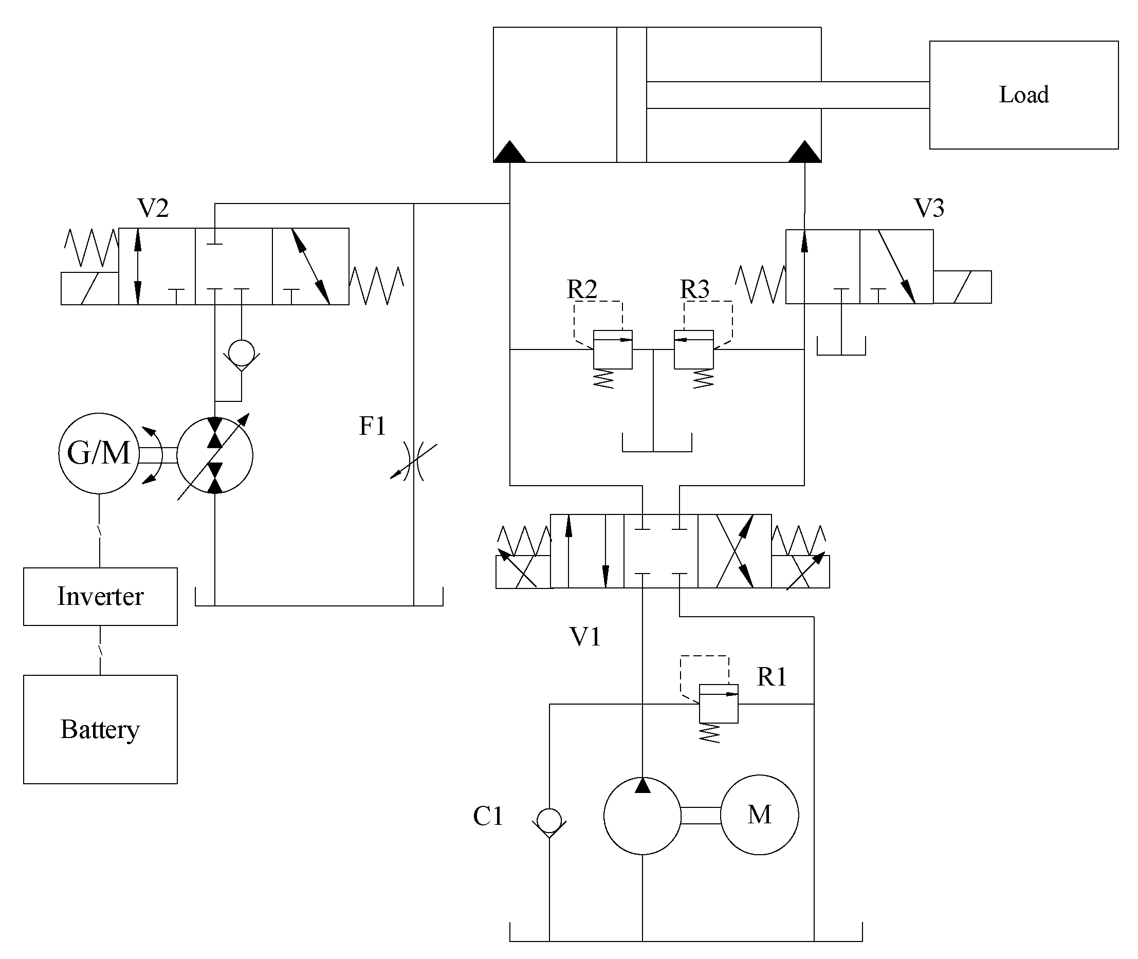
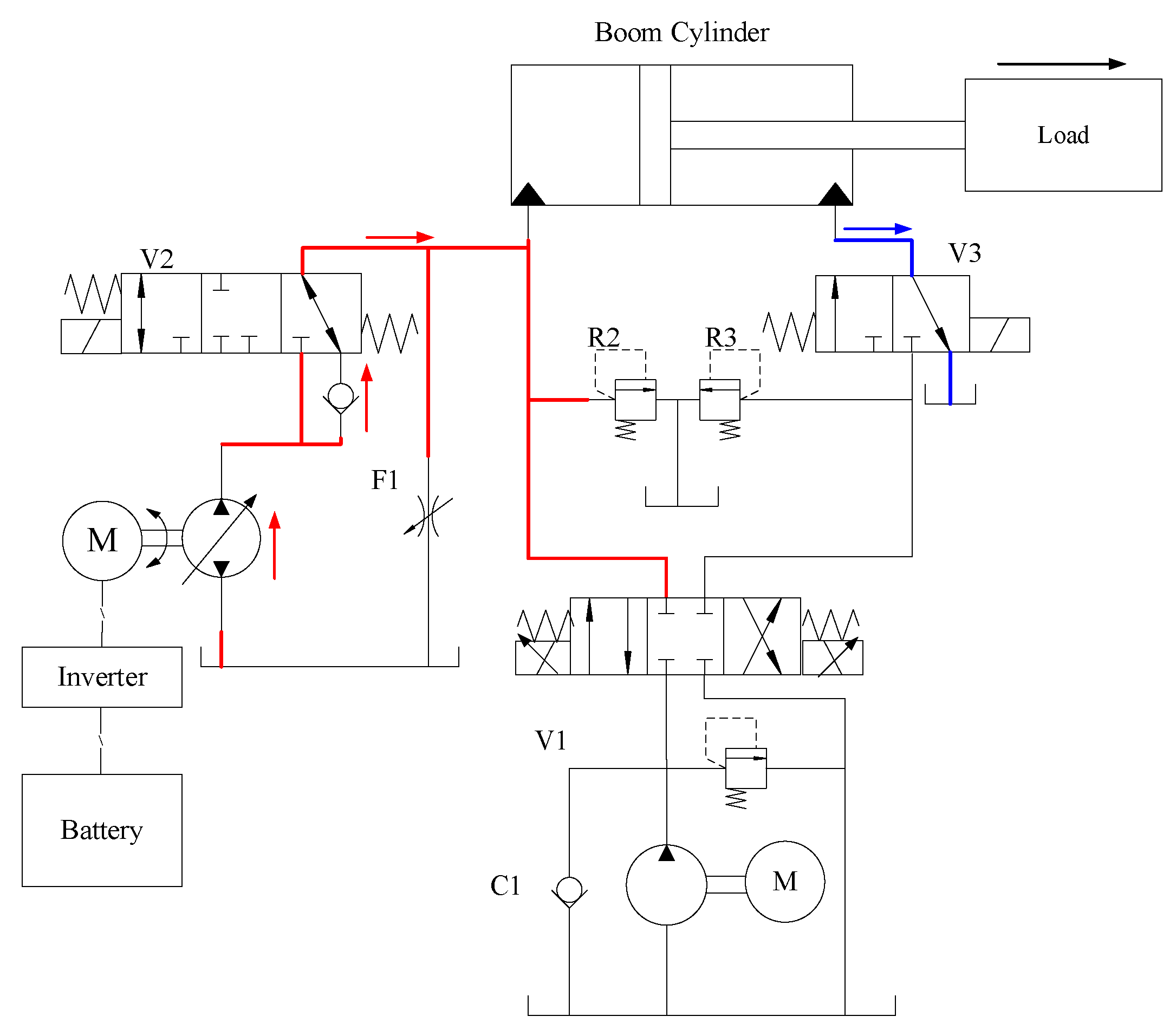
To further extend this idea, a modified boom energy regeneration system is proposed in this paper that not only inherits the novelty of the previous research but also possesses a strategy to utilize the energy captured. Figure 2 vividly depicts the proposed system in which a couple of modifications have been made to the previous circuit. Specifically, a 3-way directional valve V3 is located on the rod chamber line to increase the control strategies of the system. Different from the former circuit, a combination of an electrical generator/motor and a hydraulic motor/pump is installed at the return line of the boom cylinder. This integration introduces a new operating mode to the system so that now, it is capable of running in three different modes including normal working, energy regeneration and energy reuse.
2.2. Working Principles
In the first working mode, the proposed system operates normally as a conventional valve-controlled hydraulic system as shown in Figure 3. Since the 3-way 3 positions directional valve V2 is closed and the 3-way directional valve V3 is set in the left position, the direction, as well as the amount of flow, is both managed by the 4-way directional valve V1. As the result, operations of the boom cylinder are totally governed by the operator by controlling this valve. Although no energy is saved during this period, this mode ensures that the system can still function properly in case of unexpected failures from energy recovery components. Moreover, it is well known that the valve-controlled system provides the fastest response which can be crucial in different real-life scenarios.
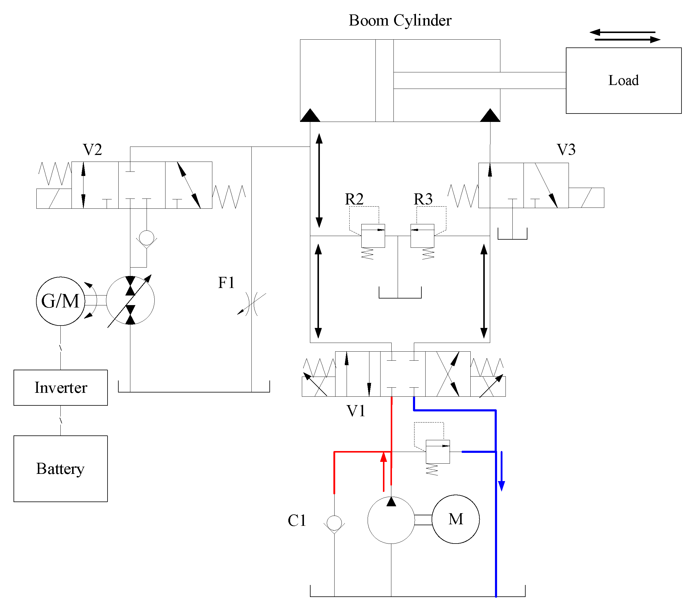
The energy regeneration mode is described graphically via Figure 4. During boom-down operation, since arm and bucket weight as well as possibly heavy load are exerting considerable pressure on the boom cylinder, the retraction process can occur naturally as a result of gravity. As the rod goes down, oil being pushed out of the piston chamber flows toward the hydraulic motor via the valve V2, which is at its left connection. The amount of hydraulic energy existing as the potential energy of the piston rod is converted into electrical energy by the generator and after that stored in a battery unit. In this mode, the main valve is set right in the middle position such that the main motor and pump can run idly. The retraction speed can be regulated by adjusting the torque of the electric generator. Under the large-load and high-velocity condition, the flow control valve F1 is then activated to rapidly alleviate the load with the hydraulic motor, as a result, ensuring good performance of the system.
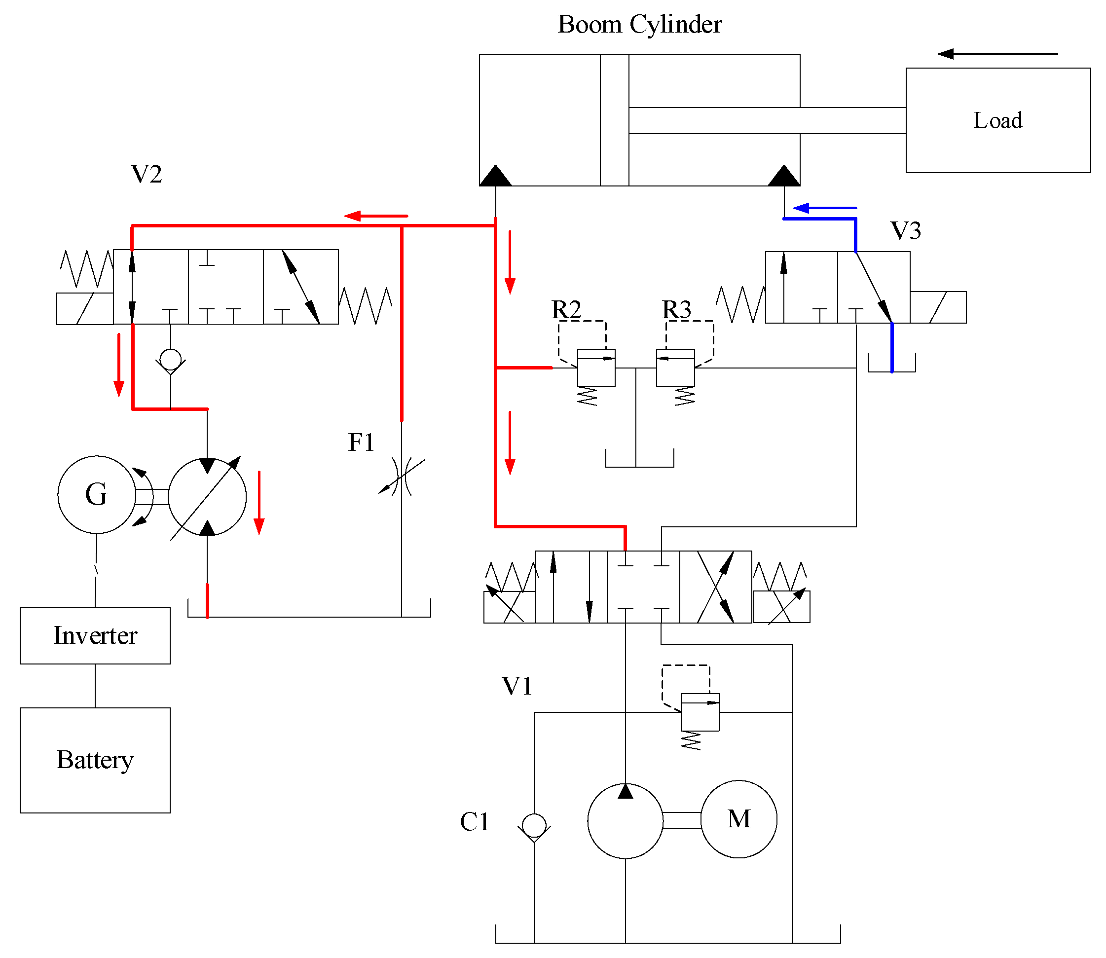
Figure 5 illustrates how regenerated energy can be effectively utilized by the reuse mode. In this mode, the functionalities of the energy recovery unit are switched. Specifically, the electrical motor/generator now is working as a motor, and the hydraulic pump/motor now is operating as a pump to lift the load. Similar to the energy regeneration mode, the main valve V1 blocks flow from both sides of the valve; whereas the 3-way direction valve V3 is at its right position allowing oil to travel back to tank immediately. The flow is supplied to the boom cylinder via the valve V2 working in the right positions.
3. Energy Management Strategy
In the previous chapter, the details of the structure and working principle were presented. The proposed system is divided into 3 operation functions: normal mode, energy regeneration mode and energy reuse mode. With different working modes, the system needs a control strategy to operate the system safely and effectively.
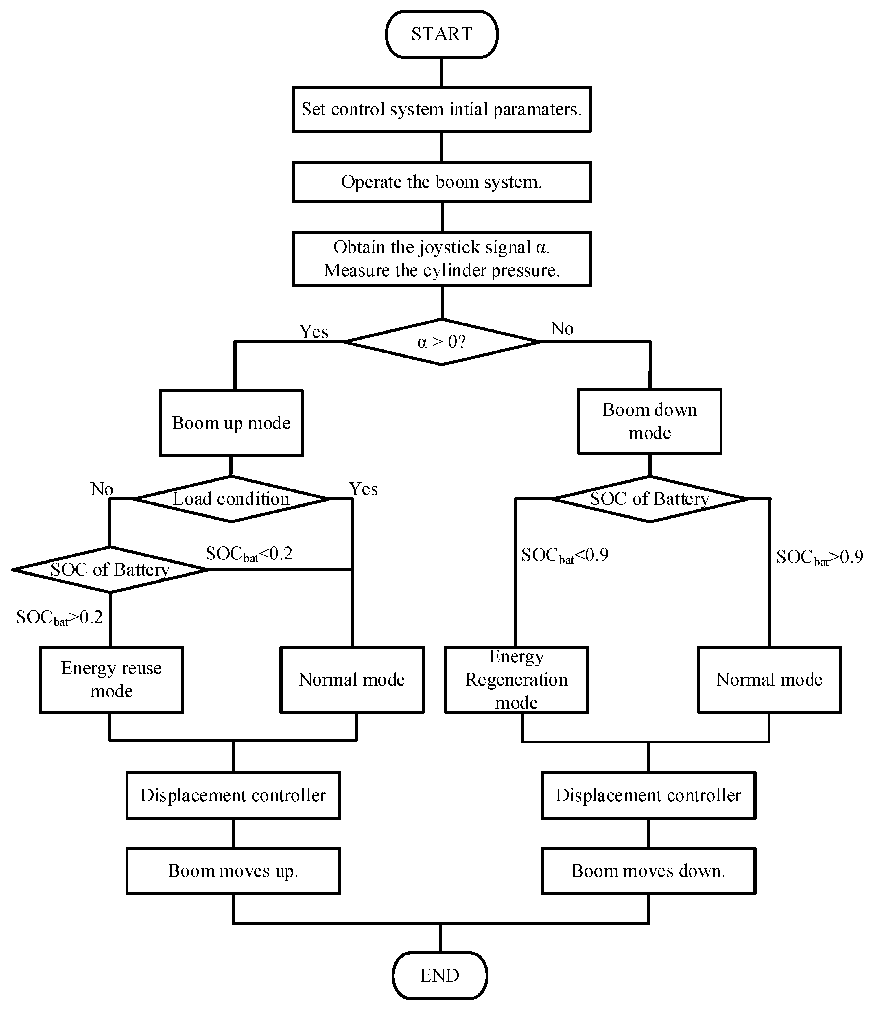
The control strategy for the proposed system is shown in Figure 6. When the system starts to operate, the system initial parameters are set to keep the current state. The operator controls the boom cylinder by using the joystick signal. We assume that the negative and positive joystick signal corresponds to the boom cylinder moving down and up, respectively.
3.1. Control Strategy of Boom down Process
In the boom moving down the process, the control strategy is designed based on the state of charge of the battery (SOCbat). During this operation, the battery works in the charging mode. Therefore, the overcharge phenomenon should be avoided because of damaging and reducing the lifetime of the device. The maximum SOCbat is chosen to be 0.9 to have a remaining capacity amount of the battery. If the SOCbat is lower than the maximum value, the energy regeneration mode is activated. The hydraulic power in the bore chamber is converted to the electrical power and stored in the battery. If the SOCbat is higher than the maximum value, the overcharge phenomenon may occur. Therefore, the normal mode is set to work.
3.2. Control Strategy of Boom up Process
In the boom moving up the process, the control strategy is designed based on the state of charge of the battery (SOCbat) and load condition. If the load condition is too high, the big size of the electrical motor/generator has to be integrated to provide enough torque requirement to lift the load. Besides, the battery supplies more power to the system. The SOCbat is quickly decreased and may result in insufficient energy to be reused for subsequent cycles. Based on these reasons, without load condition and if the SOCbat is higher than 0.2, the energy reuse mode is activated. In the case of load condition or SOCbat being lower than 0.2, the boom moves up in the normal mode.
3.3. Displacement Tracking Control Based on Discrete Time-Optimal Control
Although a typical working cycle of excavators is approximately 20 s, the amount of time available to harvest the potential energy of the boom cylinder is just about 3 s [20]. Therefore, it is evident that both tracking accuracy and convergence time are crucial in automatic control scenarios. A famous solution to the problem of time-optimal control is the Continuous Time-Optimal Control (CTOC) also well-known as the Bang-Bang control algorithm. It regulates the target system in such way that the setpoint could be efficiently reached in the shortest time possible. Its formula is as simple as below.
where , and are the control signal, position tracking error and velocity, respectively.
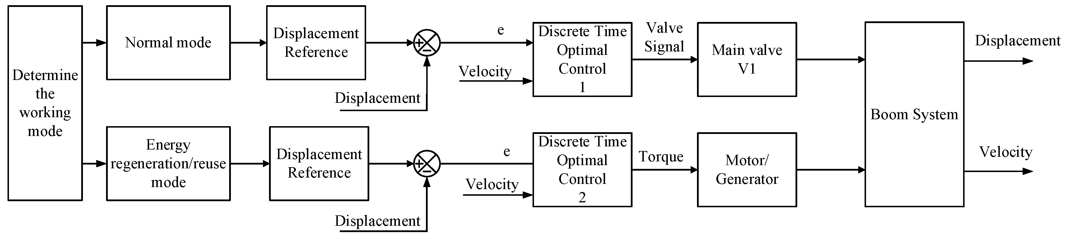
However, this control strategy exhibits serious chattering in the control signal that, consequently, hinders its potential in practical applications. To overcome this shortcoming, a remedy was then given in [24], namely Discrete Time-Optimal Control (DTOC) [25,26]. The controller is believed to successfully resolve the undesired chattering issue without making a compromise with the system performance. Two DTOC controllers were designed for controlling the main valve V1 and electric motor/generator corresponding to the normal and regeneration/reuse modes as shown in Figure 7. The DTOC algorithm, which can be easily accomplished by a digital computer, is briefly presented as follows.
where is actuator saturation limit, is the sampling period, and are temporary variables.
With the designed control strategy, the system can operate safely and effectively. The devices in the system are selected with a suitable size to avoid the high cost of the system. The battery is maintained operating in the ideal area to prevent damage and shorten life. Besides, the displacement and velocity of the boom cylinder can achieve good tracking performance.
4. Simulation Results
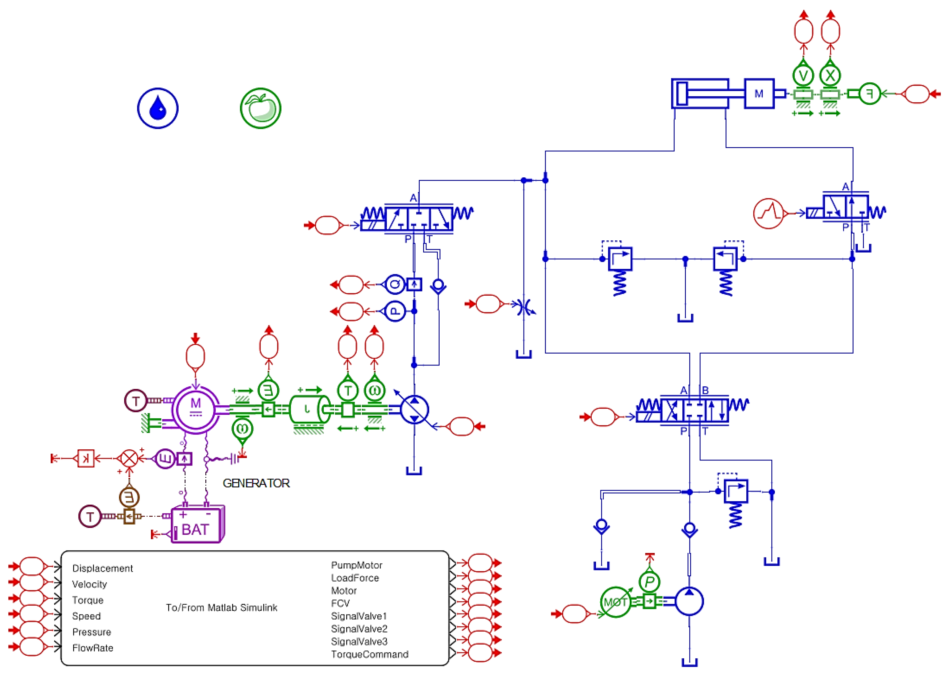
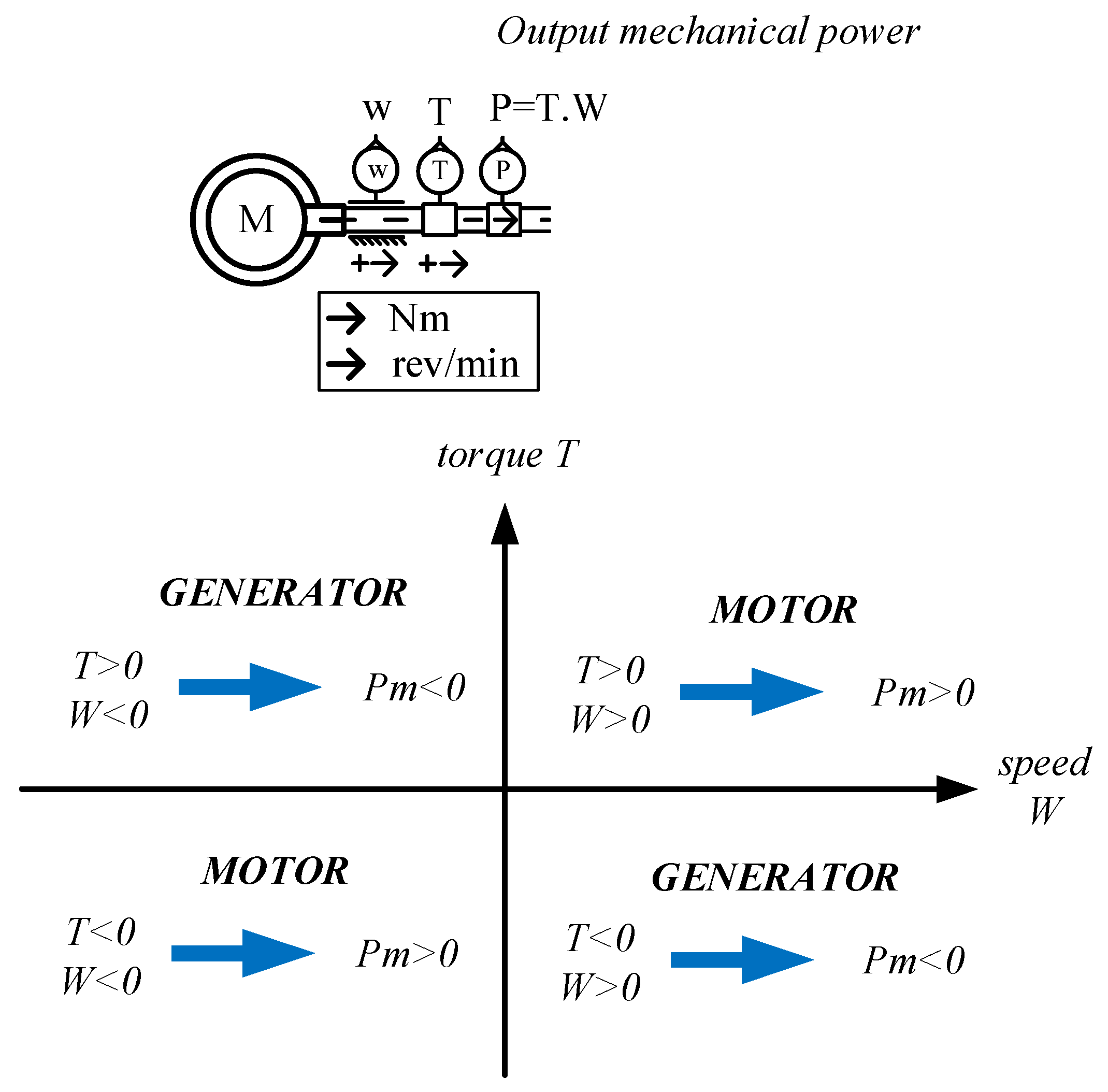
In order to completely validate the effectiveness of the proposed ERS, the co-simulation model was built in the LMS AMESim software (2019a) and Matlab 2017a as shown in Figure 8. In details, the hydraulic components are presented in blue blocks, the mechanical parts are simulated by the green blocks and the electrical devices are illustrated in the purple block, the control signals are expressed via the red functions. Two simulation software were communicated via S-Function. The configuration parameters of the proposed system are shown in Table 1. The used electric motor/generator is reversible; it can work either as a motor or as a generator. Using the motor convention, the rotor relative speed can be measured with W as an output speed at the mechanical port, and the torque can be measured with T as an output torque at the mechanical port. When W and T are of same sign, the machine is working as a motor, and the output mechanical power P is positive. When W and T are of opposite sign, the machine is working as a generator and the output mechanical power P is negative as shown in Figure 9. To meet the requirements of the energy management strategy, the initial SOC of battery is chosen 0.6. This parameter will vary depending on the energy regeneration mode or energy reuse mode during operation. The number of cells in series determines the current and voltage of the battery. If the voltage and current are too big, they can damage the device and endanger the operator. The number of cells in parallel determines the capacity of the battery. This parameter is selected to suit the excavator operating for a long period of time without exceeding the threshold limit in energy management strategy.
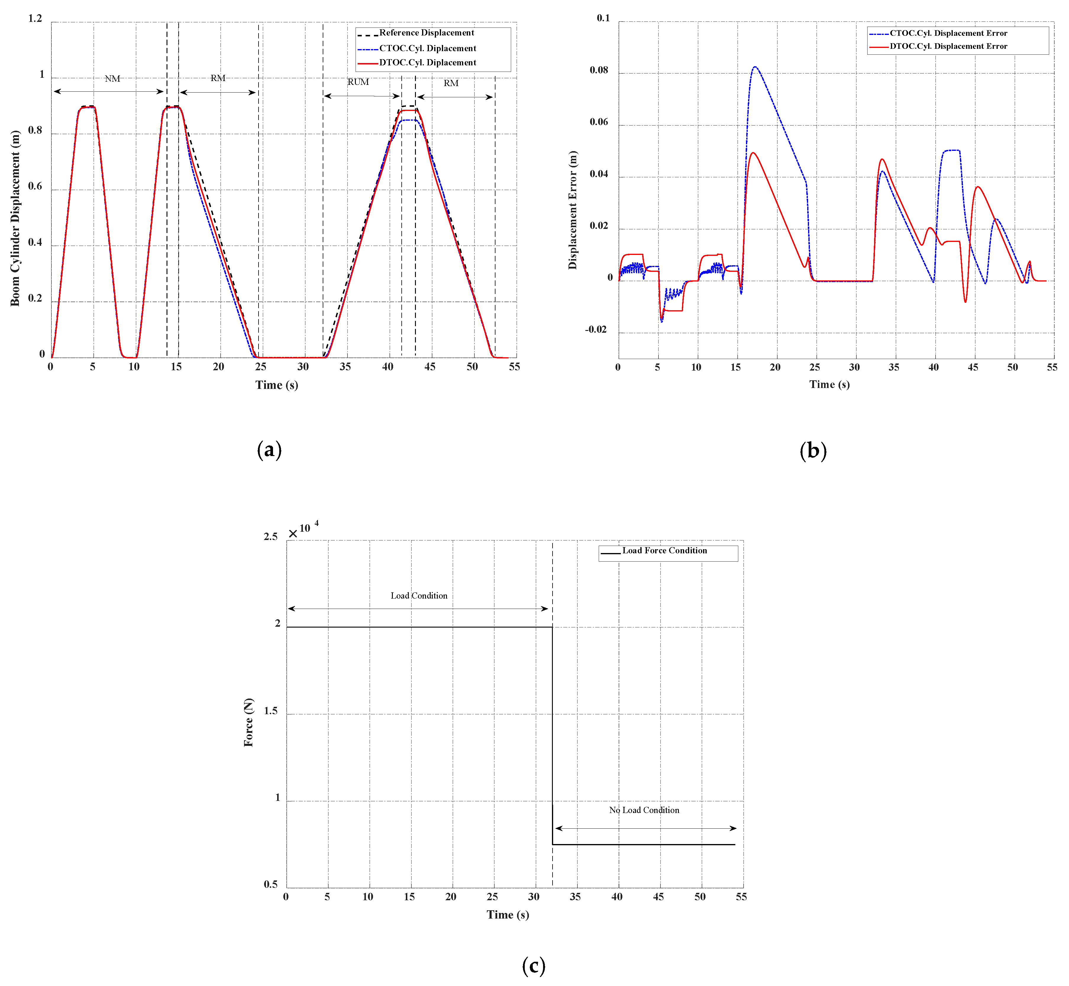
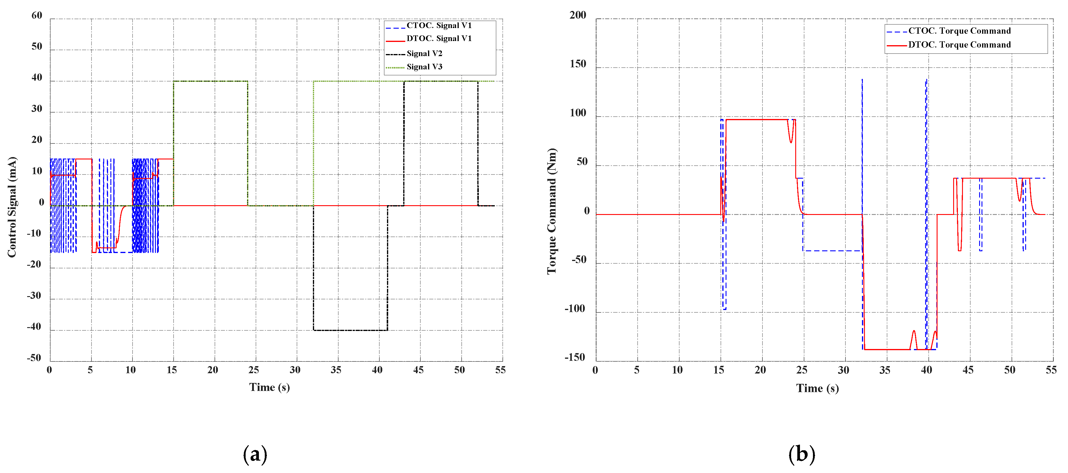
The displacement, displacement error, and load force condition of the boom cylinder are shown in Figure 10. From the 0 s to 8 s, the system run in the normal mode. The boom cylinder took three seconds to reach 0.9 m and took more than 3 s to fully retract. In the next cycle, the boom cylinder worked in the energy regeneration mode. During the extension process, the cylinder was supplied the flow rate from the main pump. From 15 s, the boom cylinder moved down, and the potential energy in the bore chamber was converted to electrical energy via the energy conversion components. In the final cycles, the hydraulic power was supplied by the electrical motor/generator and hydraulic pump/motor. Besides, to show the effectiveness of the proposed energy management strategy based on the DTOC controller, a simulation comparison with energy management strategy based on the CTOC controller was made. The CTOC controller could achieve a smaller error than DTOC controller during the normal mode operation. However, DTOC controller reduced the chartering phenomenon and helped the boom cylinder smoothly moving which clearly be shown in the control signal in Figure 10a. During the regeneration mode, the DTOC could give a more suitable signal, making the cylinder closer to the desired position from 41 s to 43 s. In addition, it could be seen that the control by the main valve helped the cylinder have better performance than the control by the generator. However, the error when controlled by the generator was also small in about 6% as shown in Figure 10b. This was an acceptable error in the boom system. The control signals were within the allowable working range of each device as shown in Figure 11. Therefore, these results proved that the control strategy could ensure the system to operate safely and accurately.
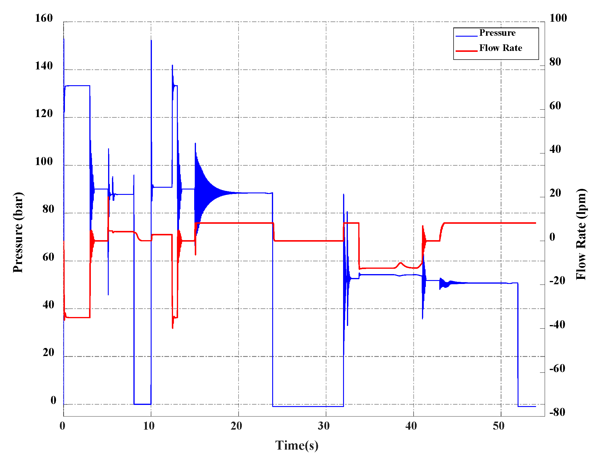
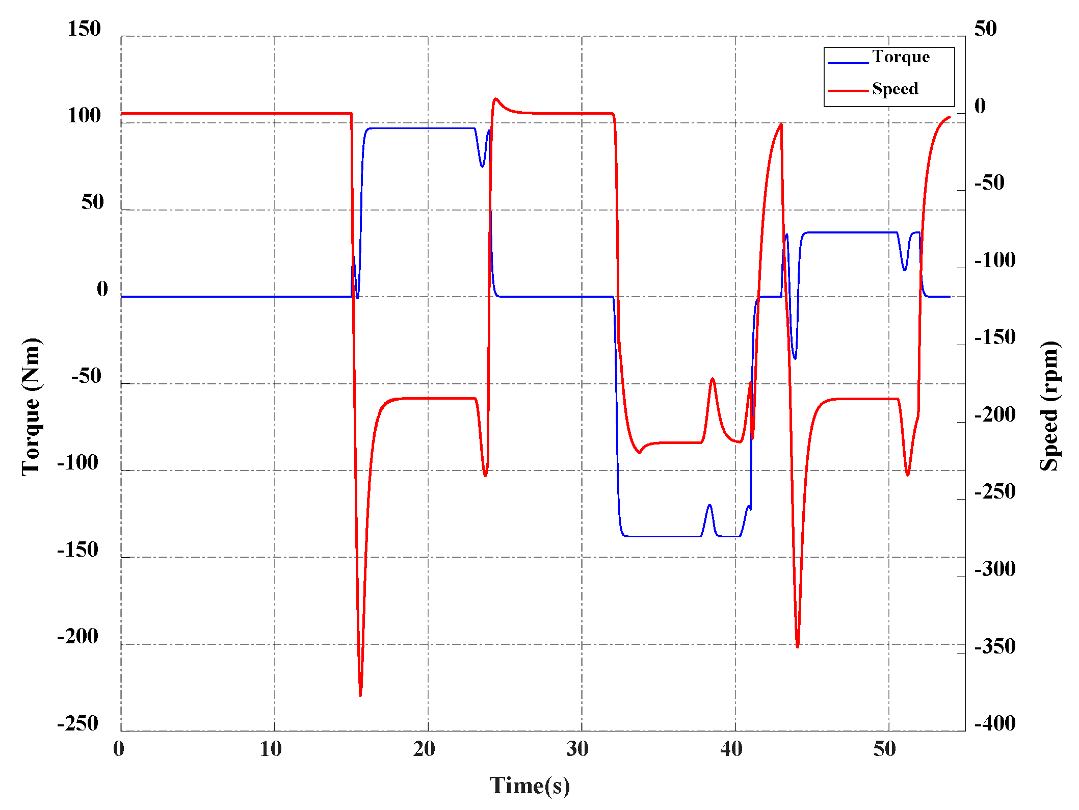
Figure 12 showed the pressure and flow rate of the boom cylinder. During the operation, the maximum volume that flows into the chamber was 38 lpm. The pressure of the boom cylinder was 135 bar in the load condition. The speed and torque of the electrical motor/generator were presented in Figure 13. The speed and torque were different signs when the electric motor/generator operated in the generator mode to recover energy. From the 32 s to 43 s, the electrical motor/generator worked in the motor function. Therefore, the speed and torque were the same signs. The highest torque and speed of the electrical motor/generator were 400 rpm and 200 Nm in the energy reuse mode. In addition, the voltage and current of the battery were shown in Figure 14. Then, the regenerated energy of the proposed system could be estimated.
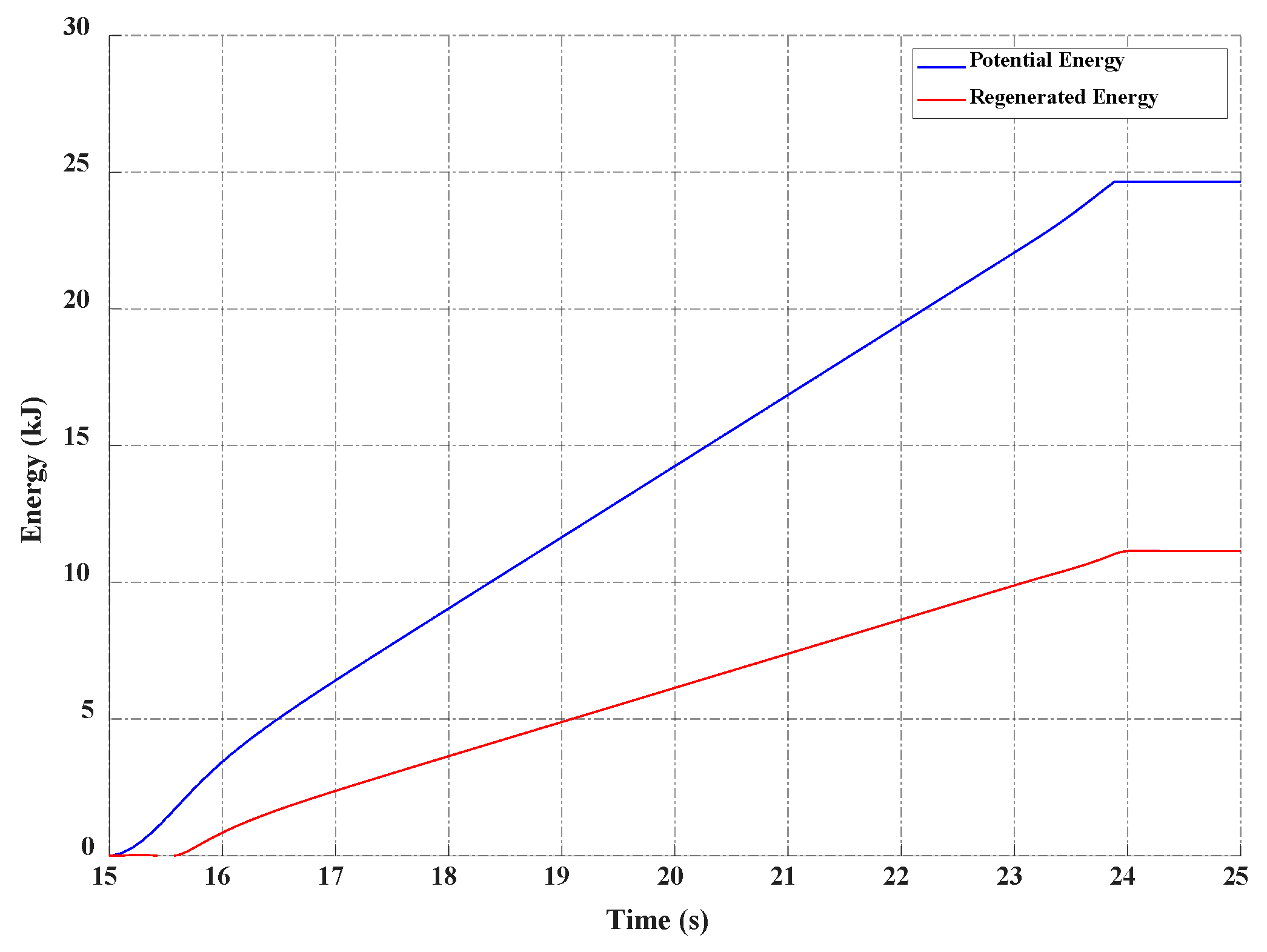
The potential energy can be calculated as shown in Equation (3).
where the Ep, pc and qc are the potential energy, pressure and flow rate of the bore chamber, respectively. The hydraulic energy was converted to the electrical energy and stored in the battery. The regenerated energy can be calculated as shown in Equation (4).
where the Er, Ur, and Ir are the regenerated energy, voltage and current of the battery. The energy efficiency of the proposed ERS can be calculated as follows:
Based on the above equations, Figure 15 showed the energy analysis of the proposed ERS. From the simulation results, the potential energy and regenerated energy were 24.9 kJ and 10.956 kJ. Then, the energy regeneration efficiency of the system could achieve 44%.
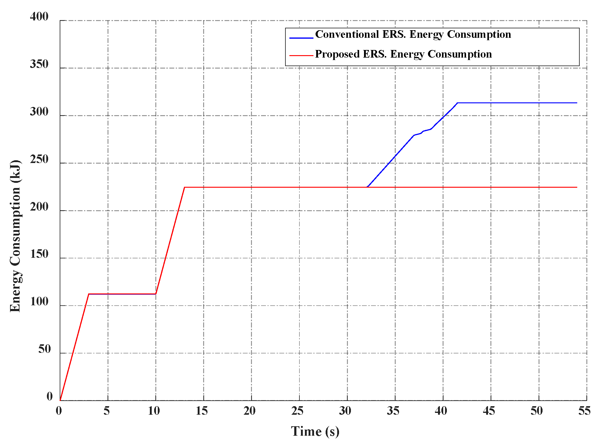
A comparison energy consumption of the conventional ERS and proposed ERS was shown in Figure 16. The result showed that with the reuse mode, the proposed ERS could lift up the boom cylinder without flow rate from the main pump by using the stored energy in the battery through the energy conversion components in case of no load. The energy that could be saved through the use of regenerated energy from the boom cylinder was 88.74 kJ. Through all the results, it can be seen that the proposed system could work in different operation modes with each working requirement to be able to recover and reuse energy efficiently, along with accuracy and stable based on the proposed energy management strategy.
5. Conclusions
This paper presented a boom energy regeneration system which regenerated the potential energy from the bore chamber of the boom cylinder and reused the stored energy in the next cycles. The proposed ERS used energy conversion components which included an electrical motor/generator, and a hydraulic pump/motor could work in three operation modes: normal mode, energy regeneration mode, and especially the energy reuse mode which is often neglected in previous studies. To operate the system safely and accurately, an energy management strategy with DTOC controllers is designed based on the load condition and SOC of battery. An AMESim simulation model was built to validate the effectiveness of the proposed system. The results proved that the system could work well with the proposed energy management strategy. The error of the cylinder displacement and the reference signal was in the range 0.08 m. The energy regeneration efficiency of the system could reach 44%. Moreover, the energy reuse mode has also been proven, the cylinder can lift in the no-load condition without power from the main pump by using the stored energy in the battery through the energy conversion components. Then, the energy consumption of the system was reduced up to 88.74 kJ. In future work, a real test bench will be built. Besides, an energy management strategy with optimization methods will be applied to the proposed system to enhance energy efficiency.
Author Contributions
K.K.A. was the supervisor providing funding and administrating the project, and he reviewed and edited the manuscript. T.C.D. carried out the investigation, methodology, analysis, and validation; made the MATLAB and AME Sim software and wrote the original manuscript. D.G.N. carried out the simulations and checked the structure of the paper. T.D.D. checked the manuscript and supported the model for research. All authors have read and agreed to the published version of the manuscript.
Funding
This research was supported by Basic Science Program through the National Research Foundation of Korea (NRF) funded by the Ministry of Science and ICT, South Korea (NRF-2020R1A2B5B03001480).
Institutional Review Board Statement
Not applicable.
Informed Consent Statement
Not applicable.
Data Availability Statement
Thank you very much. We have understood and agreed to the policies of the MDPI publisher.
Conflicts of Interest
The authors declare no conflict of interest.
References
- Do, T.C.; Truong, H.V.A.; Dao, H.V.; Ho, C.M.; To, X.D.; Dang, T.D.; Ahn, K.K. Energy Management Strategy of a PEM Fuel Cell Excavator with a Supercapacitor/Battery Hybrid Power Source. Energies 2019, 12, 4362. [Google Scholar] [CrossRef] [Green Version]
- Dang, T.D.; Do, T.C.; Truong, H.V.A.; Ho, C.M.; Dao, H.V.; Xiao, Y.Y.; Jeong, E.; Ahn, K.K. Design, Modeling and Analysis of a PEM Fuel Cell Excavator with Supercapacitor/Battery Hybrid Power Source. J. Drive Control 2019, 16, 45–53. [Google Scholar]
- Truong, H.V.A.; Dao, H.V.; Do, T.C.; Ho, C.M.; To, X.D.; Dang, T.D.; Ahn, K.K. Mapping Fuzzy Energy Management Strategy for PEM Fuel Cell–Battery–Supercapacitor Hybrid Excavator. Energies 2020, 13, 3387. [Google Scholar] [CrossRef]
- Dinh, T.X.; Thuy, L.K.; Tien, N.T.; Dang, T.D.; Ho, C.M.; Truong, H.V.A.; Dao, H.V.; Do, T.C.; Ahn, K.K. Modeling and Energy Management Strategy in Energetic Macroscopic Representation for a Fuel Cell Hybrid Electric Vehicle. J. Drive Control 2019, 16, 80–90. [Google Scholar]
- Kim, S.; Park, J.; Kang, S.; Kim, P.Y.; Kim, H.J. A robust control approach for hydraulic excavators using μ-synthesis. Int. J. Control Autom. Syst. 2018, 16, 1615–1628. [Google Scholar] [CrossRef]
- Du, H.; Xiong, W.; Li, Q.; Wang, L. Friction Characteristics of a Cylinder Based on a Bridge-Type Pneumatic Energy-saving Circuit. Int. J. Control Autom. Syst. 2019, 17, 145–154. [Google Scholar] [CrossRef]
- Oh, K.-S.; Seo, J.-H. Inertial parameter estimation of an excavator with adaptive updating rule using performance analysis of Kalman filter. Int. J. Control Autom. Syst. 2018, 16, 1226–1238. [Google Scholar] [CrossRef]
- Hu, J.; Sun, Q.; Zhao, Y.; Hu, J. Sliding Mode Control for We-energy Based on Markovian Jumping Systems. Int. J. Control Autom. Syst. 2019, 17, 1793–1802. [Google Scholar] [CrossRef]
- Lin, T.; Chen, Q.; Ren, H.; Huang, W.; Chen, Q.; Fu, S. Review of boom potential energy regeneration technology for hydraulic construction machinery. Renew. Sustain. Energy Rev. 2017, 79, 358–371. [Google Scholar] [CrossRef]
- Yu, Y.-X.; Ahn, K.K. Energy Saving of an Electric Forklift with Hydraulic Accumulator. In Proceedings of the 2019 19th International Conference on Control, Automation and Systems (ICCAS), Jeju, Korea, 15–18 October 2019; pp. 408–411. [Google Scholar]
- Yu, Y.-X.; Ahn, K.K. Optimization of energy regeneration of hybrid hydraulic excavator boom system. Energy Convers. Manag. 2019, 183, 26–34. [Google Scholar] [CrossRef]
- Do, T.; Jeong, E.; Ahn, K. Research on the Energy Regeneration Systems for Hybrid Hydraulic Excavators. KSFC Conf. 2018, S5-3, 137–141. [Google Scholar]
- Shen, W.; Jiang, J.; Su, X.; Reza Karimi, H. Control strategy analysis of the hydraulic hybrid excavator. J. Frankl. Inst. 2015, 352, 541–561. [Google Scholar] [CrossRef]
- Ge, L.; Dong, Z.; Quan, L.; Li, Y. Potential energy regeneration method and its engineering applications in large-scale excavators. Energy Convers. Manag. 2019, 195, 1309–1318. [Google Scholar] [CrossRef]
- Liu, J.; Jiao, Z.; Xian, F.; Liu, W. Energy recovery and utilization system of excavator boom based on flow regeneration and balance theory. J. Braz. Soc. Mech. Sci. Eng. 2019, 42, 35. [Google Scholar] [CrossRef]
- Yu, Y.-X.; Das, D.; Truong, B.N.M.; Kwan, A.K. A Study on the Energy Regeneration System of Boom for Hybrid Hydraulic Excavator. In Proceedings of the International Conference on Control, Automation and Systems, Busan, Korea, 13–16 October 2015. [Google Scholar]
- Li, J.; Zhao, J.; Zhang, X. A Novel Energy Recovery System Integrating Flywheel and Flow Regeneration for a Hydraulic Excavator Boom System. Energies 2020, 13, 315. [Google Scholar] [CrossRef] [Green Version]
- Yoon, J.I.; Truong, D.Q.; Ahn, K.K. A generation step for an electric excavator with a control strategy and verifications of energy consumption. Int. J. Precis. Eng. Manuf. 2013, 14, 755–766. [Google Scholar] [CrossRef]
- Lin, T.; Wang, Q.; Hu, B.; Gong, W. Research on the energy regeneration systems for hybrid hydraulic excavators. Autom. Constr. 2010, 19, 1016–1026. [Google Scholar] [CrossRef]
- Lin, T.; Huang, W.; Ren, H.; Fu, S.; Liu, Q. New compound energy regeneration system and control strategy for hybrid hydraulic excavators. Autom. Constr. 2016, 68, 11–20. [Google Scholar] [CrossRef]
- Chen, Q.; Lin, T.; Ren, H.; Fu, S. Novel potential energy regeneration systems for hybrid hydraulic excavators. Math. Comput. Simul. 2019, 163, 130–145. [Google Scholar] [CrossRef]
- Wang, T.; Wang, Q. Efficiency analysis and evaluation of energy-saving pressure-compensated circuit for hybrid hydraulic excavator. Autom. Constr. 2014, 47, 62–68. [Google Scholar] [CrossRef]
- Wang, T.; Wang, Q. An Energy-Saving Pressure-Compensated Hydraulic System With Electrical Approach. IEEE/ASME Trans. Mechatron. 2014, 19, 570–578. [Google Scholar] [CrossRef]
- Jinqing, H.; Lulin, Y. The discrete form of tracking-differentiator. J. Syst. Sci. Math. Sci. 1999, 19, 268–273. [Google Scholar]
- Gao, Z. On discrete time optimal control: A closed-form solution. In Proceedings of the 2004 American Control Conference, Boston, MA, USA, 30 June–2 July 2004; pp. 52–58. [Google Scholar]
- Gao, Z.; Hu, S. On properties and applications of a new form of discrete time optimal control law. In Proceedings of the Conference Record of the 2004 IEEE Industry Applications Conference, 2004. 39th IAS Annual Meeting, Seattle, WA, USA, 3–7 October 2004; pp. 1511–1518. [Google Scholar]
Figure 1.
Hydraulic circuit of the previous research.

Figure 2.
Hydraulic circuit of the proposed system.

Figure 3.
Working principle of normal mode.

Figure 4.
Boom-down operation in energy regeneration mode.

Figure 5.
Stored energy used to drive boom cylinder upward in reuse mode.

Figure 6.
Control strategy of the proposed system.

Figure 7.
Displacement tracking control based on discrete time-optimal control.

Figure 8.
The proposed simulation model in AMESim software.

Figure 9.
Working principle of the electric motor/generator.

Figure 10.
Displacement (a), error of the boom cylinder (b) and load force condition (c) (NM: normal mode, RM: regeneration mode, RUM: Reuse mode).
Figure 10.
Displacement (a), error of the boom cylinder (b) and load force condition (c) (NM: normal mode, RM: regeneration mode, RUM: Reuse mode).

Figure 11.
Comparison control signal of each valve (a) and torque command (b).

Figure 12.
Pressure and flow rate of the boom cylinder.

Figure 13.
Torque and speed at the shaft of electrical motor/generator.

Figure 14.
Voltage and current of the battery.

Figure 15.
Energy analysis of the proposed ERS.

Figure 16.
Comparison of energy consumption of the conventional ERS and proposed ERS.


Table 1.
Setting parameter of the proposed system.
| Components | Parameter | Value |
|---|---|---|
| Cylinder | Bore diameter | 65 mm |
| Rod diameter | 42 mm | |
| Length | 1 m | |
| Pump | Displacement | 50 cc/rev |
| Electrical motor | Speed | 1500 rpm |
| Pump/Motor | Displacement | 100 cc/rev |
| Generator/motor | Power | 10 kW |
| Maximum torque | 200 Nm | |
| Maximum speed | 1000 rpm | |
| Battery | Cell Capacity | 3.3 Ah |
| Internal resistance | 0.005 Ohm | |
| Number of cells in series | 40 | |
| Number of cells in parallel | 10 | |
| Initial SOC | 0.6 |
Publisher’s Note: MDPI stays neutral with regard to jurisdictional claims in published maps and institutional affiliations. |
© 2020 by the authors. Licensee MDPI, Basel, Switzerland. This article is an open access article distributed under the terms and conditions of the Creative Commons Attribution (CC BY) license (http://creativecommons.org/licenses/by/4.0/).
Share and Cite
MDPI and ACS Style
Do, T.C.; Nguyen, D.G.; Dang, T.D.; Ahn, K.K. A Boom Energy Regeneration System of Hybrid Hydraulic Excavator Using Energy Conversion Components. Actuators 2021, 10, 1. https://doi.org/10.3390/act10010001
AMA Style
Do TC, Nguyen DG, Dang TD, Ahn KK. A Boom Energy Regeneration System of Hybrid Hydraulic Excavator Using Energy Conversion Components. Actuators. 2021; 10(1):1. https://doi.org/10.3390/act10010001
Chicago/Turabian StyleDo, Tri Cuong, Duc Giap Nguyen, Tri Dung Dang, and Kyoung Kwan Ahn. 2021. "A Boom Energy Regeneration System of Hybrid Hydraulic Excavator Using Energy Conversion Components" Actuators 10, no. 1: 1. https://doi.org/10.3390/act10010001
Note that from the first issue of 2016, this journal uses article numbers instead of page numbers. See further details here.