Article

Analysis of Heat Exchange Efficiency and Influencing Factors of Energy Tunnels: A Case Study of the Torino Metro in Italy

1
School of Civil Engineering, Southeast University, No. 2, Southeast University Road, Nanjing 211189, China
2
Department of Geotechnical Engineering, College of Civil Engineering, Tongji University, 1239 Siping Road, Shanghai 200092, China
*
Author to whom correspondence should be addressed.
Buildings 2025, 15(15), 2704; https://doi.org/10.3390/buildings15152704
Submission received: 24 June 2025 / Revised: 26 July 2025 / Accepted: 29 July 2025 / Published: 31 July 2025

Abstract

Both ground source heat pumps (GSHPs) and energy underground structures are engineered systems that utilize shallow geothermal energy. However, due to the construction complexity and associated costs of energy tunnels, their heat exchange efficiency relative to GSHPs remains a topic worthy of in-depth investigation. In this study, a thermal–hydraulic (TH) coupled finite element model was developed based on a section of the Torino Metro Line in Italy to analyze the differences in and influencing factors of heat transfer performance between energy tunnels and GSHPs. The model was validated by comparing the outlet temperature curves under both winter and summer loading conditions. Based on this validated model, a parametric analysis was conducted to examine the effects of the tunnel air velocity, heat carrier fluid velocity, and fluid type. The results indicate that, under identical environmental conditions, energy tunnels exhibit higher heat exchange efficiency than conventional GSHP systems and are less sensitive to external factors such as fluid velocity. Furthermore, a comparison of different heat carrier fluids, including alcohol-based fluids, refrigerants, and water, revealed that the fluid type significantly affects thermal performance, with the refrigerant R-134a outperforming ethylene glycol and water in both heating and cooling efficiency.

1. Introduction

Geothermal energy is a green, renewable, and clean energy source characterized by large reserves, wide geographic distribution, and stable output [1,2]. It can be broadly categorized based on the heat transfer mechanism, temperature range, and methods of development and utilization [3,4,5]. These categories include shallow geothermal energy, hydrothermal geothermal energy, and hot dry rock resources [6]. Among these, shallow geothermal energy, typically found within the upper 500 m of the Earth’s surface, has gained particular attention due to its accessibility and comparability with urban infrastructure [7,8]. Its exploitation is most commonly achieved through ground source heat pump (GSHP) systems [9,10], which enable efficient heat exchange between the ground and built environment for both heating and cooling applications [11,12].
Traditional GSHP systems typically rely on drilling and the installation of buried pipe networks, involving high initial costs and significant land area. Furthermore, systems that require groundwater reinjection pose the potential risk of contaminating water resources. In contrast, the technology for energy underground structures offers a more integrated and sustainable approach by utilizing building foundation components and underground structures as ground heat exchangers (GHEs) to extract shallow geothermal energy. Heat exchange pipes are embedded directly within these structural components, thereby eliminating the need for groundwater reinjection and significantly reducing the land footprint. This method not only mitigates environmental risks but also improves sustainability by making use of existing construction elements [13]. Moreover, no additional capital investment is required as the system makes use of the thermal conductivity of concrete and the contact between the structural components and the surrounding ground, thereby enhancing heat exchange efficiency and contributing to energy savings and emission reductions [14].
An energy tunnel is a type of underground energy structure that harnesses shallow geothermal energy by embedding heat exchange pipes into the tunnel linings. These tunnels typically extend over considerable lengths and benefit from relatively stable environmental temperatures. Despite their potential for sustainable energy integration, the broader adoption of energy tunnels remains limited due to implementation costs and technical challenges, and continued research and development are required. Currently, two main construction approaches are employed for embedding heat exchange pipes into tunnel linings: (1) Inner-Surface Installation: This method involves attaching heat exchange pipes directly to the inner surface of the tunnel lining. It was first applied in China to provide heating in tunnels located in cold regions [15,16]. Similar implementations have been carried out in Sydney’s urban tunnels (Australia) [17] and the geothermal system in the Stuttgart subway station (Germany) [18]. Over time, this method has evolved into more advanced configurations, including energy anchors, energy geotextiles [19], and capillary networks [20]. (2) Precast Segment Integration: In this method, heat exchange pipes are embedded within precast concrete lining segments, making it particularly suitable for shield tunnels constructed using tunnel boring machines (TBMs), mostly in urban areas. The Jenbach Tunnel (Austria) marked the first application of this technique [21]. Subsequent projects employing this method include the Turin Metro Tunnel in Italy [22,23], the Warsaw Metro Tunnel in Poland [24], and the Tsinghua Park section of the Jingzhang Railway Tunnel in China [25].
With the continued expansion of urban metro systems worldwide, underground transportation tunnels are increasingly recognized for their potential to harness shallow geothermal energy for sustainable heating and cooling applications [26,27,28,29]. Among the key factors that determine the feasibility and performance of such systems is heat transfer. In this regard, a comprehensive theoretical framework and extensive engineering experience have been established for GSHP systems. These analytical methods can provide useful references for evaluating the thermal behavior of energy tunnels [30,31]. However, due to the significant differences in geometric and boundary conditions between tunnel structures and conventional ground heat exchangers, i.e., boreholes or pile-type GHEs, it is necessary to consider the unique characteristics of tunnel linings and address potential challenges specific to heat transfer in tunnel environments.
This study is based on the engineering case of rings 179 and 180 of the Torino Metro Line 1 shield tunnel in Italy. It focuses on the design and thermal performance of energy tunnel segments, with particular attention to the thermo-hydraulic (TH) behavior of the system. Key geological and thermal parameters are examined to evaluate how various factors influence heat transfer efficiency, with the aim of informing more accurate cost–benefit assessments of energy tunnel applications and providing a theoretical foundation for future studies. This includes advancing the understanding of thermo-hydro-mechanical (THM) coupling, exploring the integration of geothermal utilization systems with other tunnel infrastructure, and improving the overall design and implementation of energy tunnels. The specific research objectives are as follows:
(1)
To develop and validate a thermal–hydraulic (TH) coupled finite element model of a tunnel ring segment from the Torino Metro Line using COMSOL Multiphysics.
This objective involves constructing a detailed TH coupled model that integrates solid heat transfer, porous media heat transfer, and non-isothermal pipe flow using COMSOL Multiphysics simulation. The model accounts for geological conditions, tunnel ventilation, and the coupled thermo-hydraulic behavior of the energy segment system. The simulation results under both heating and cooling scenarios are compared with those from Barla’s work [20] to verify model accuracy and reliability.
(2)
To conduct an environmental sensitivity analysis on key parameters affecting heat transfer efficiency.
Following model validation, the effects of various environmental factors—including groundwater conditions, tunnel air velocity, and the physical properties of the heat carrier fluid—on the overall heat transfer efficiency of the energy system are investigated. These parameters are systematically varied to evaluate their relative impact on the system and to inform more robust design considerations.
(3)
To perform a comparative analysis of the heat transfer efficiency between energy-tunnel-lining heat-exchange segments and traditional GSHPs.
This objective entails comparing key indicators, such as the total heat transfer and outlet temperature of the heat exchange pipes, between ground heat exchangers (GHEs) embedded in tunnel linings and conventional U-shaped GSHP systems. The analysis aims to highlight the relative advantages and limitations of each system in terms of thermal efficiency and partial applicability.

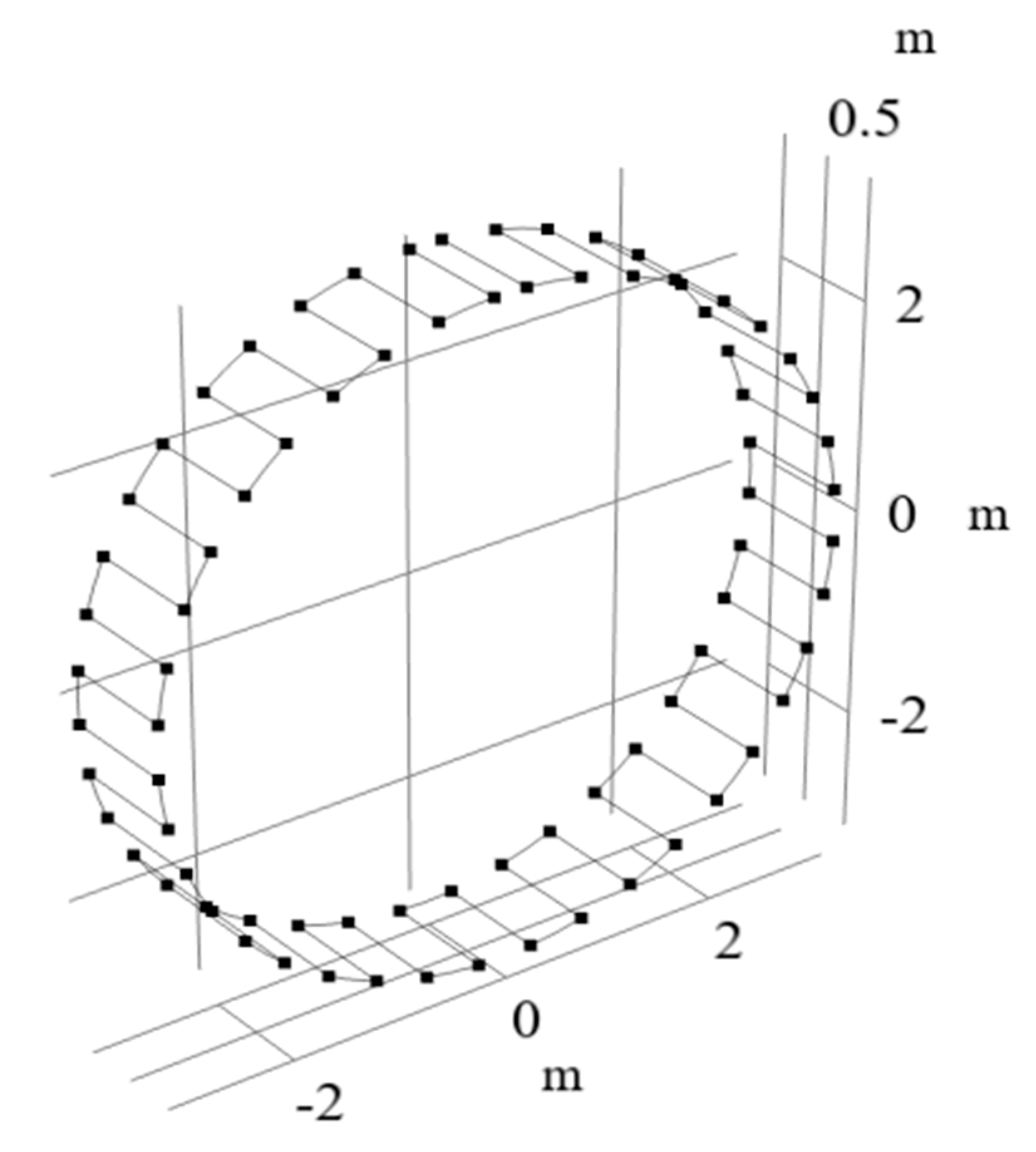
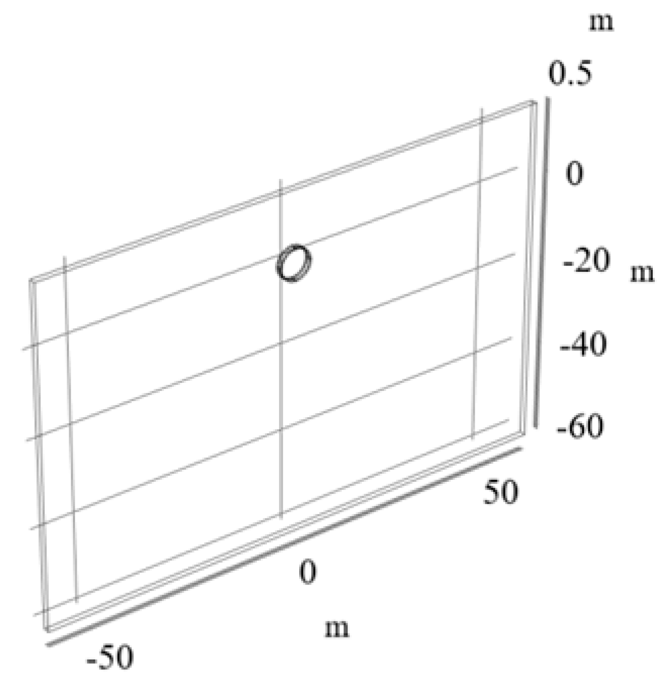
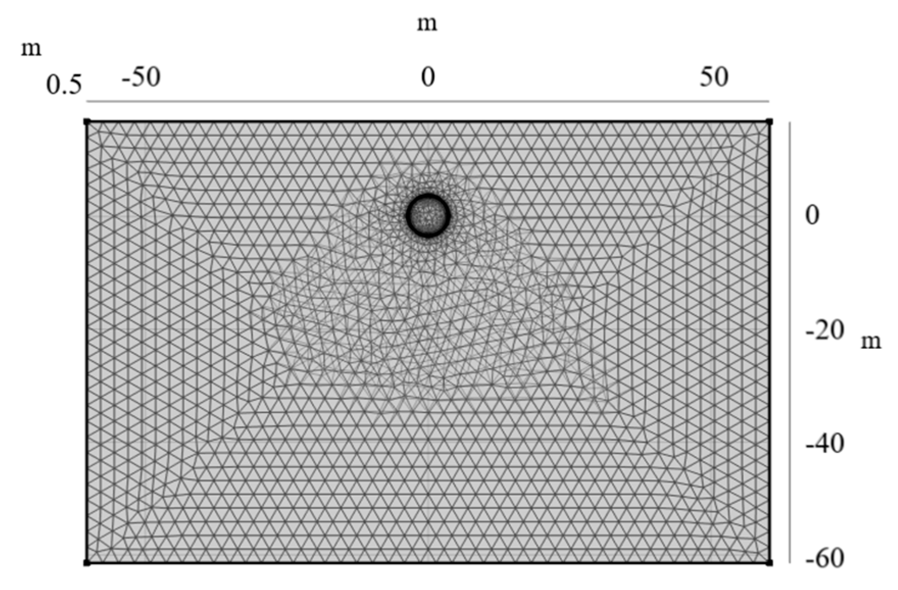
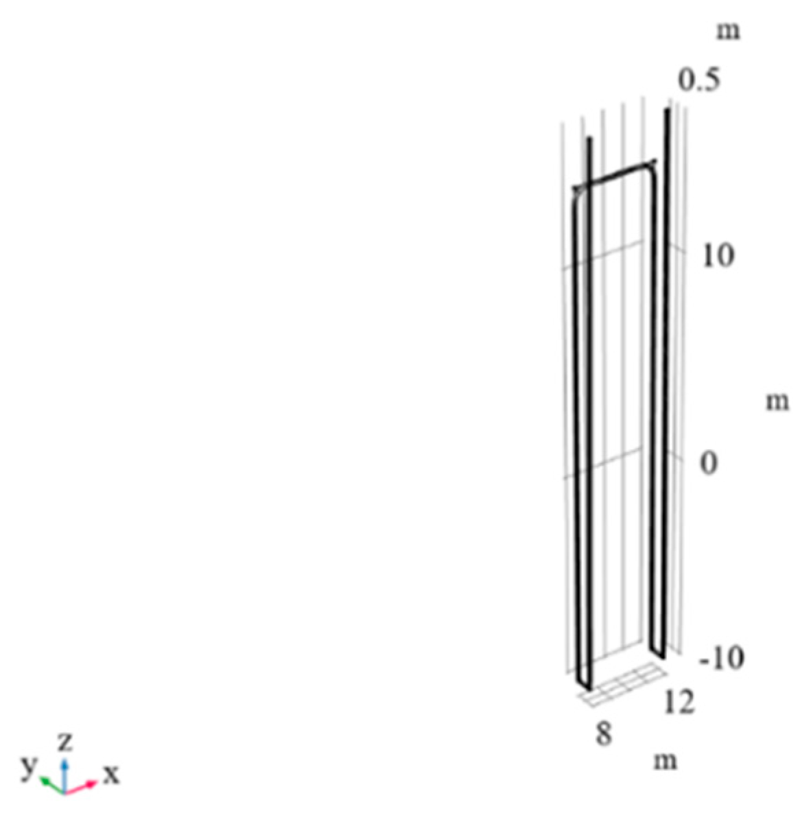
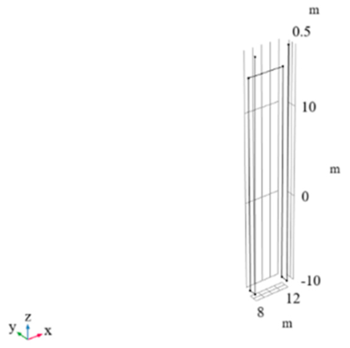
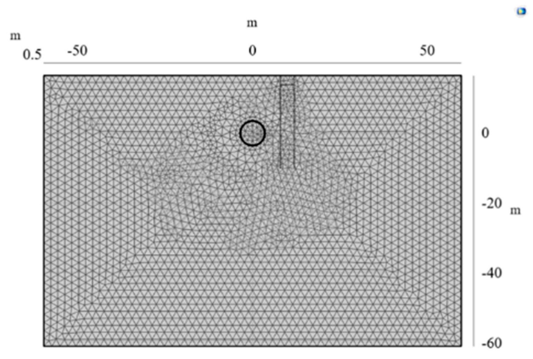
2. Establishment of a 3D Thermal–Hydraulic Coupled FEM Model

The research object of this study is the second segment connecting Porta Nuova Station and Lingotto Station within rings 179 and 180 of the Torino Metro Line 1 shield tunnel in Italy. This section spans approximately 1.9 km, includes two stations, and extends to Benghazi Square. The tunnel was excavated using an Earth Pressure Balance Tunnel Boring machine (TBM), with a shield diameter of approximately 8 m. The average cover depth is 21.5 m, located nearly below the local groundwater table. The tunnel lining comprises precast concrete rings, each 30 cm thick and assembled from seven individual segments using the TBM. Heat exchange inlet and outlet pipes are embedded along the tunnel’s sidewalls beneath pedestrian safety passages. Tunnel ventilation is maintained through multiple ventilation shafts that introduce external air, resulting in a cold-activated thermal boundary condition within the tunnel environment. Previous modeling efforts for this segment, including thermal–hydraulic analysis, were carried out by Barla [31]. A detailed description of the model can be found in reference [22].
To ensure that the numerical model accurately reflects real-world conditions, COMSOL Multiphysics was employed for the development of the TM coupled finite element model. The model comprises a 1.4 m longitudinal section of the Torino Metro Tunnel, specifically focusing on rings 179 and 180. It includes the surrounding soil, the annular concrete tunnel lining, and GHEs embedded within the lining segments. The simulation incorporates multiple physical fields, including solid heat conduction, heat transfer in porous media, non-isothermal pipe flow, and water migration in soil, modeled using Darcy’s law, in order to capture the thermo-hydraulic coupling behavior of the system. This multiphysics approach allows for a comprehensive analysis of heat transfer mechanisms under realistic geological and operational conditions. For the sake of computational efficiency, the thermal properties of the soil were assumed to be homogeneous, and Darcy’s law was applied to simplify the simulation of seepage flow in this study.
To model the embedded ground heat exchangers (GHEs) in the tunnel linings, two simulation strategies were considered in COMSOL. The first approach involved detailed 3D modeling of the GHEs based on actual pipeline geometry, using high-density polyethylene (HDPE) as pipe boundary material and water as the internal medium. This setup, implemented using the non-isothermal pipe flow physical interface, closely represents physical conditions. However, due to the high length-to-diameter ratio and turbulent flow characteristics, this approach led to significant meshing complexity and computational overhead. The second modeling approach simplifies the GHEs using one-dimensional line elements with the same non-isothermal flow interface. Thermal interaction is handled through the wall heat transfer sub-interface, with pipe diameter defined accordingly. This simplified method preserves essential thermal behavior while substantially reducing simulation time and resource requirements. Given the balance between accuracy and efficiency, the 1D approach was selected for this study, as illustrated in Figure 1, with the parameters listed in Table 1.
To accurately represent the operating conditions of the Torino Metro Line, a three-dimensional model was used to simulate soil around the tunnel cross-section, despite the shorter longitudinal extent compared to its lateral dimensions. The solid heat transfer module was used to model thermal conduction in the tunnel lining and surrounding ground. Considering airflow within the tunnel and groundwater seepage in surrounding soils, fluid and porous media heat transfer modules were also incorporated. The surrounding soil, a complex three-phase medium, was simulated using a typical porous media heat transfer model. Factors influencing heat transfer efficiency include the thermal conductivities of solid and liquid phases, soil porosity, and the hydraulic gradient. The tunnel lining, comprising reinforced concrete, was treated as a porous construction material. Due to the material’s heterogeneity, its effective thermal capacity and conductivity were obtained through field experiments and incorporated into the model. The physical parameters used for the geological formation and tunnel lining are summarized in Table 2 from Barla’s research, and the 3D model is illustrated in Figure 2.
Selecting the appropriate finite element mesh is critical for achieving accurate, reliable, and computationally efficient results. In this research, a tetrahedral element mesh was employed and iteratively refined through seven comparative analyses. The number of elements tested ranged from 14,522 to 29,689. After evaluating the trade-offs between accuracy and computational efficiency, the final mesh configuration consisted of 14,522 tetrahedral elements. Mesh refinement significantly affects calculation accuracy, with finer meshes capturing local gradients and thermal variations more accurately. However, increased mesh density also leads to longer computational time and greater resource consumption. To ensure model stability and reduce numerical errors, mesh quality metrics such as the skewness, aspect ratio, and element distortion were carefully monitored. The final mesh was selected based on the skewness-based quality assessment method, yielding the following characteristics: minimum element quality of 0.03991, average element quality of 0.5, element volume ratio of 1.239 × 10⁻⁴, mesh volume of 13,070.0 m3, and 4288 mesh vertices, as presented in Figure 3. Since the current model includes a circular tunnel structure, some reduction in the mesh quality in certain regions was inevitable during the meshing process.

3. Methodology and Validation of the Model

3.1. Equation for Heat Transfer

  • Darcy’s Law
The classic Darcy’s law can be employed to describe the fluid flow in saturated soil and rock masses. Darcy’s equations succinctly analyze the process by which groundwater flows from regions of higher hydraulic head to lower hydraulic head under the influence of gravitational and pressure gradients. The equations are expressed as follows:
t ( n ρ ) + · ( ρ u ) = Q m
u = k μ ( p + ρ g )
where ρ [kg/m3] represents the density of the fluid material (groundwater); n is the porosity of the soil; u [m/s] denotes the Darcy velocity; Q m [m3/s] signifies the magnitude of the flow rate; k [m2] is the permeability coefficient of the Darcy fluid, modeled by the hydraulic conductivity; μ [Pa·s] is the dynamic viscosity of the Darcy fluid; g [m/s] i is gravitational acceleration; and p [Pa] indicates the pressure drop.
2.
Pipe Heat Transfer
In the ground heat exchanger system considered in this paper, heat transfer occurs through multiple mechanisms. Inside the pipe, convective heat transfer dominates as the working fluid flows. Simultaneously, thermal conduction also takes place through the pipe wall and continues into the surrounding concrete lining and soil. This allows the system to either absorb heat from the environment or dissipate it into the surrounding soil, enabling heat flow from regions of higher to lower temperature. Furthermore, taking into account heat losses through the pipe wall, the heat transfer relationship between the fluid inside the pipe and the external environment can be described by the following equation:
ρ A C p T t + ρ A C p u · T = V · ( A k V T ) + f D ρ A 2 d h | u | 3 + Q + Q w a u
Q w a l l = ( h z ) e f f ( T e x t T )
where ρ [kg/m3] represents the density of the heat carrier fluid inside the pipe, while Cp [J/(kg·K)] denotes its specific heat capacity at constant pressure. The thermal conductivity of the fluid is expressed in k [W/(m·K)], and u [m/s] indicates the flow velocity within the pipe. The term fD corresponds to the Darcy friction factor, which reflects the roughness of the inner pipe wall and affects the convective heat transfer behavior. These parameters collectively define the heat exchange characteristics between the flowing fluid and the surrounding environment through a combination of convective and conductive processes.
3.
Total Heat Transfer and Unit-Area Heat Transfer
Q = m ˙ C p ( T o u t T i n )
Q s = Q   /   2 π r L
where the total heat transfer is Q [W], and the unit-area heat transfer is Qs [W/m2]. At the inlet, the point temperature is defined as Tin [K], while the outlet temperature of the heat carrier fluid is denoted as Tout [K]. The term m ˙ [kg/s] represents the mass flow rate of the heat carrier fluid at the outlet, with units of kilograms per second (kg/s). Cp [J/(kg·K)] is the specific heat capacity of the heat carrier fluid, which is a function of temperature.

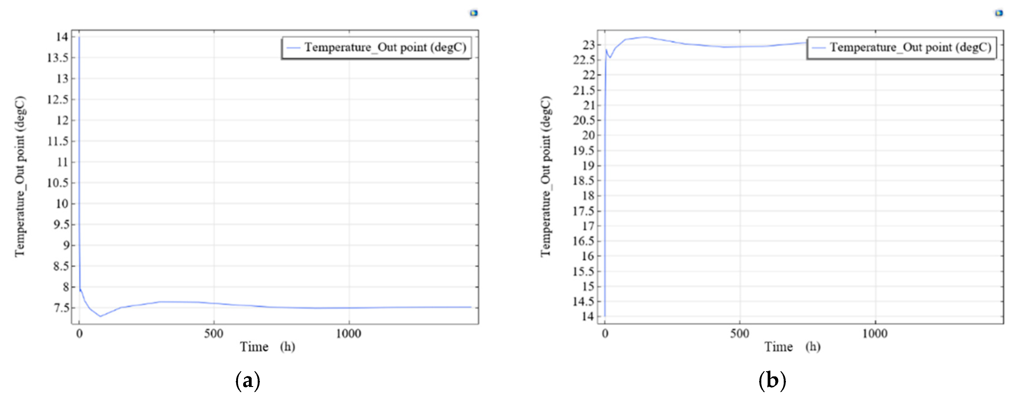
3.2. Model Validation

Barla [22,31] conducted field experiments on the southern extension section of the Torino Metro Tunnel in Italy. According to the results of on site monitoring, the average heat transfer rate Qs of the energy tunnel segments for rings 179 and 180 was calculated to be 51.3 W/m2, showing only a 2.7% deviation from the simulation results obtained using the finite element software FEFLOW.
From Barla’s simulation results [22,26,31] for the tunnel segment outlet fluid temperatures under both winter and summer loading conditions, after 30 days of continuous operation, the numerical simulation resulted in outlet temperatures of 7.05 °C in winter and 23.73 °C in summer. It can be observed from the curves that the outlet temperature of the energy segments remains relatively constant after approximately 10 days of loading, supporting the validity of the modeling approach.
Based on the thermo-hydraulic coupled model established in this study, a simulation was conducted using the constant inlet temperature method, with a loading time of 1440 h (i.e., 60 days) for both summer and winter as these are the seasons with the most significant environmental temperature demands. In winter, the inlet temperature of the heat carrier fluid was set to 4 °C, which is significantly lower than the ground temperature; under this condition, shallow geothermal energy acts as a heat source. In summer, the inlet temperature of the heat carrier fluid was set to 28 °C, which is significantly higher than the ground temperature; in this case, shallow geothermal energy acts as a cooling source. The analysis results are shown in Figure 4.
By comparing Barla’s research [26] and Figure 4, it can be observed that the simulation results in this study exhibit a trend similar to the results reported by Barla [17,20], with the final numerical results presented in Table 3.
The simulation results in this study closely match those of Barla [31], with an error of only 0.59% after 60 days of continuous loading in winter, demonstrating excellent agreement; in summer, the error after 60 days of continuous loading was 9.4%, although the numerical values were still very close. These findings indicate that the three-dimensional simulation model developed in this study successfully reproduces the experimental results of the energy tunnel of Torino Metro Line 1 in Italy. Therefore, the FEM model used in this study demonstrates reasonable and effective choices in terms of physical field selection, three-dimensional model simplification, boundary condition settings, and thermal environment parameter selection. This model provides a reliable foundation for further improvements and theoretical support for subsequent comparative experiments.

4. Results and Discussion

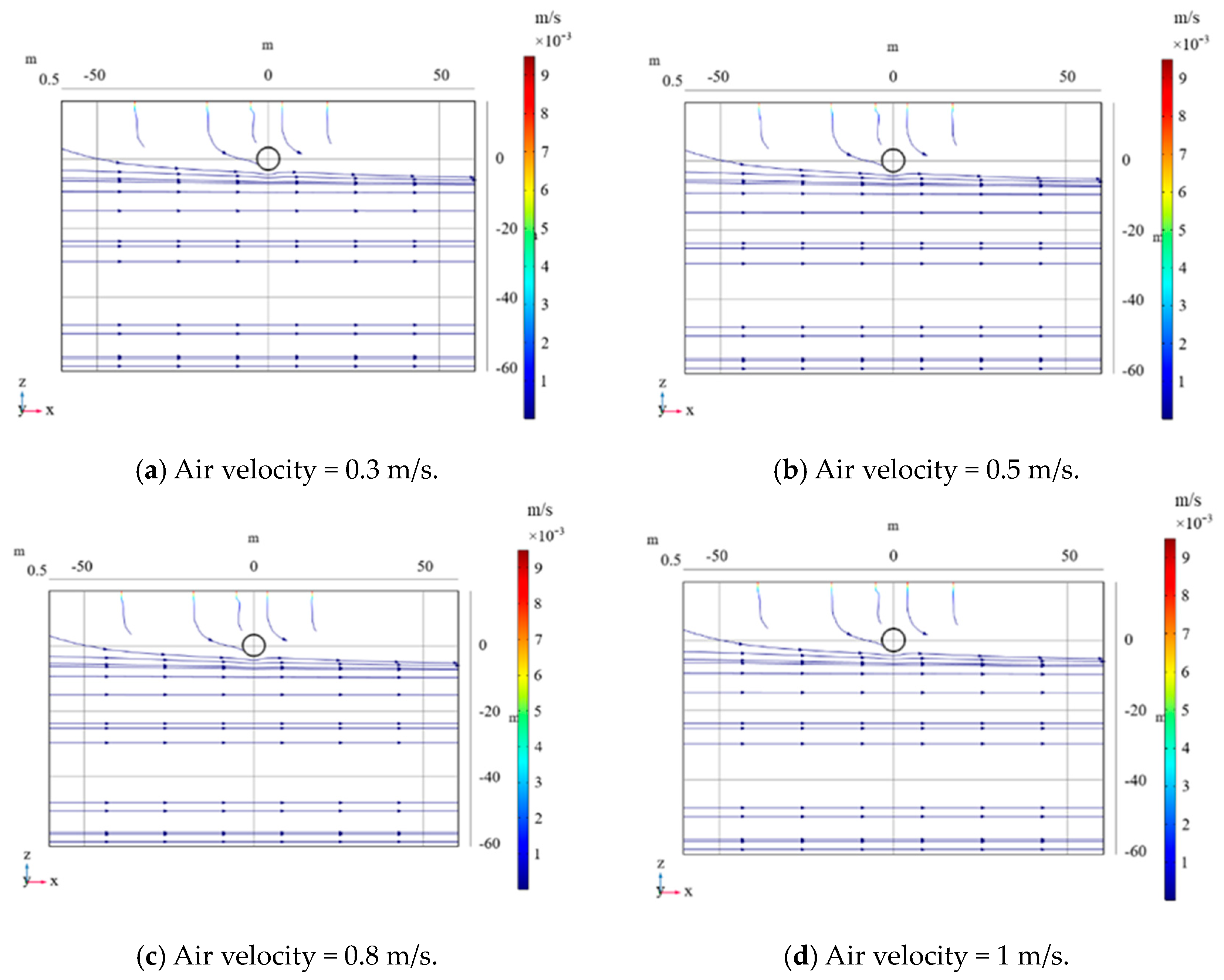
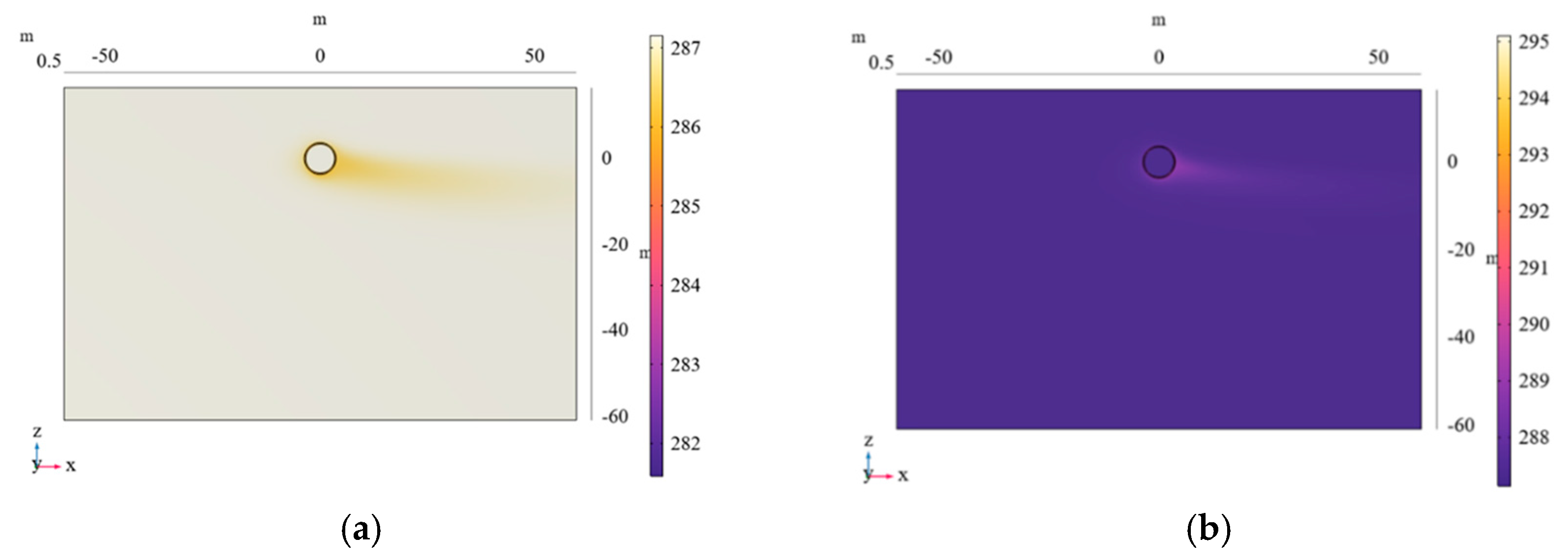
4.1. Analysis of the Influence of Air Velocity in the Tunnel

In this study, the tunnel conditions in Torino, Italy, were simulated. Based on Barla’s research [31], the temperature of the soil surrounding the tunnel was set to 14 °C, and the groundwater level was set at 12 m below the ground surface according to actual site conditions.
Since Darcy’s law was applied uniformly to the model—including the concrete tunnel lining, heat exchange pipe segments, air inside the tunnel, and the porous soil outside the tunnel—it was necessary to consider the ventilation conditions inside the tunnel. It was assumed that the average air velocity inside the tunnel is 0.5 m/s throughout the year. A parametric scan of the air velocity inside the tunnel was conducted, varying from 0.3 m/s to 1.0 m/s, in order to verify the accuracy of the finite element calculations and the rationality and validity of the model. The simulation results are shown in Figure 5.
The comparison in Figure 5 reveals that the air velocity inside the tunnel had minimal impact on the solution of the Darcy velocity field, indicating that the modeling results are accurate. Moreover, the airflow inside the tunnel, the external disturbances affecting the air field, and the tunnel’s ventilation have a limited influence on the Darcy seepage model. This finding aligns with real-world conditions and further confirms that the model is consistent with the actual operational conditions of the tunnel.

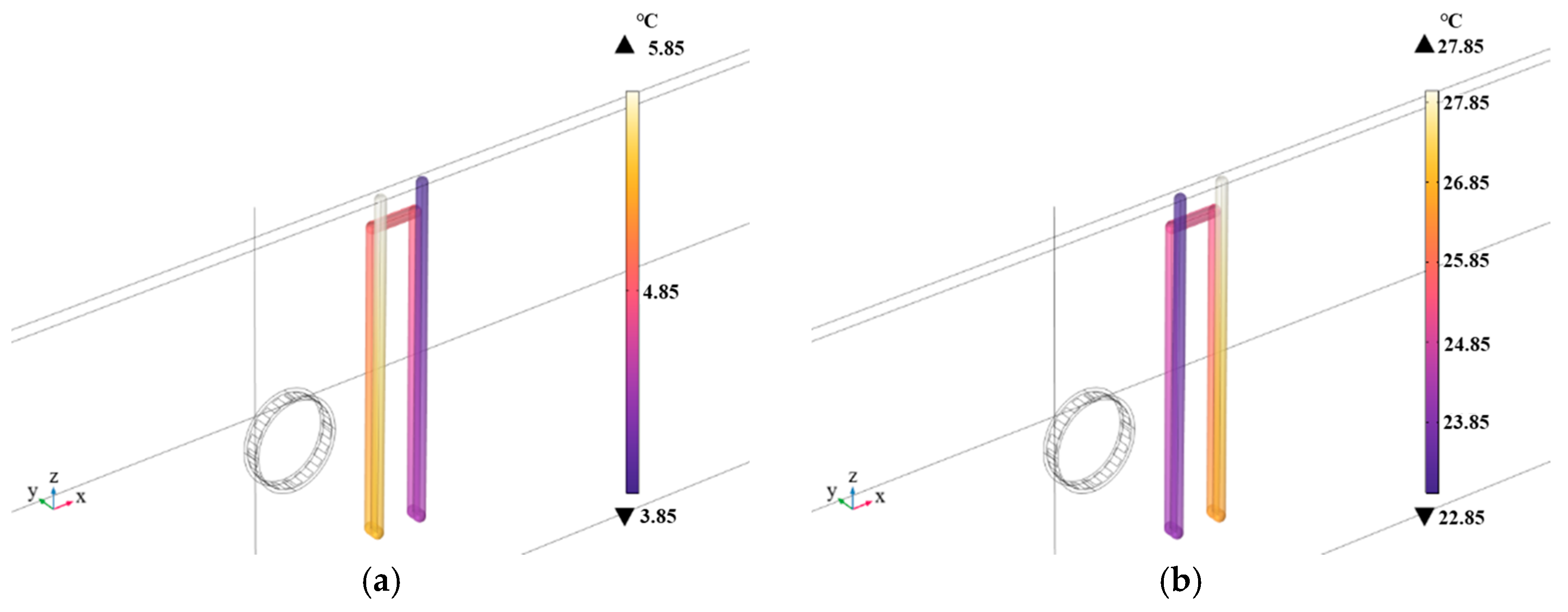
4.2. Comparative Analysis of Heat Transfer Efficiency Between Energy Tunnels and GSHPs

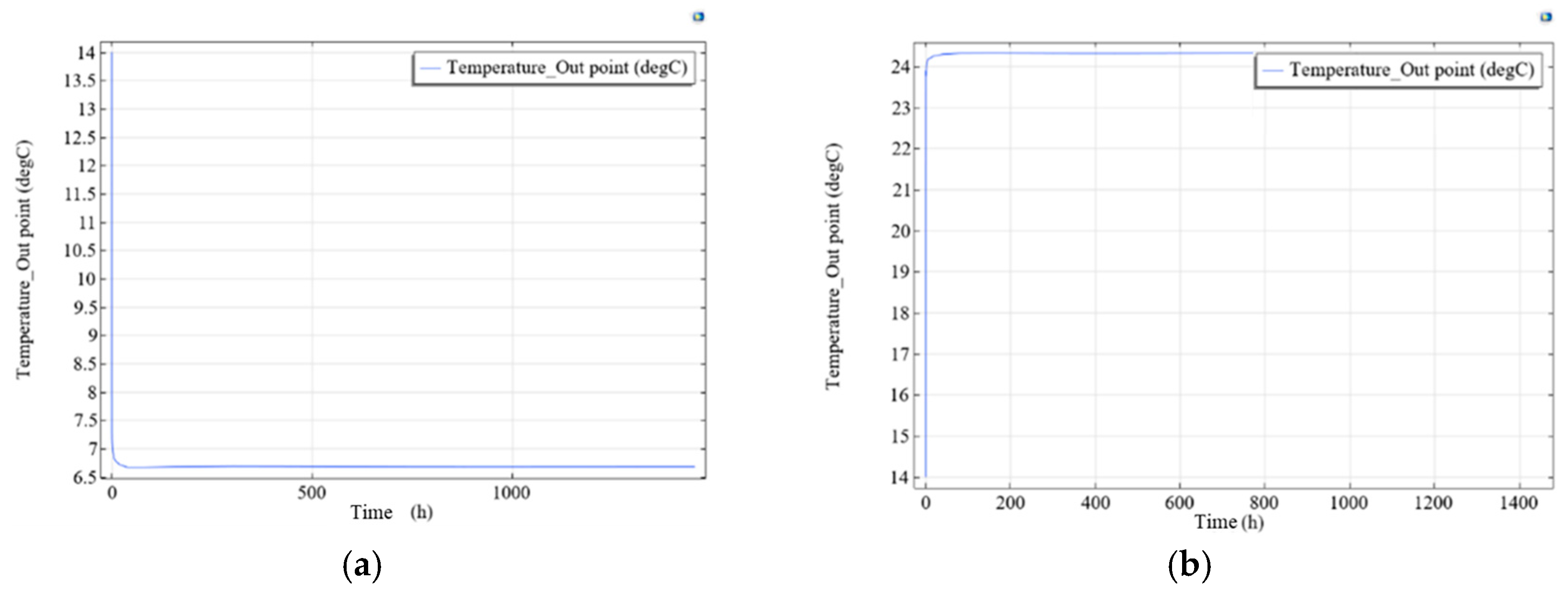
4.2.1. Analysis of Energy Tunnel Heat Transfer Efficiency

In this study, a Thermal Performance Test (TPT) was conducted using the constant inlet temperature method to assess the seasonal heat transfer performance of the energy tunnel. By simulating 60 days (1440 h) of continuous loading, the outlet temperature variations and heat transfer efficiency of the tunnel were analyzed.
In winter, the inlet temperature of the heat carrier fluid was set to 4 °C, which is significantly lower than the ground temperature of 14 °C. Under this condition, the shallow geothermal energy acts as a heat source, enabling the GHEs to extract heat from the surrounding soil and the tunnel lining. This energy can be used for building heating and can also prevent local frost damage and road icing within the tunnel. As observed in Figure 4a, the outlet temperature dropped rapidly, reached its minimum after 80 h, and then gradually stabilized at 7.55 °C after around 500 h. During the loading process, the heat exchange segments extracted shallow geothermal energy from the environment. According to the calculation formulas for system heat transfer Q and unit-area heat transfer QS, the simulated tunnel heat exchanger absorbed a total heat amount of 1.66 kW over 60 days, with an average heat absorption of 55.56 W/m2 for the heat exchange pipe.
In summer, the inlet temperature of the heat carrier fluid was set to 28 °C, significantly higher than the ground temperature of 14 °C. In this case, the shallow geothermal energy acts as a cooling source; the GHEs extract heat from the ground and the surrounding environment to provide cooling for buildings and mitigate heat accumulation within the tunnel. The outlet temperature variation curve of the heat exchange pipe during the summer season is shown in Figure 4b. A similar trend can be seen: the outlet temperature reached an extremum after 80 h and then stabilized at 23.00 °C after 500 h. The total heat transfer to the ground was calculated as 2.12 kW, with an average heat absorption of 70.95 W/m2 over the 60-day period.
The temperature field interface diagrams of the geological formation in winter and summer are shown in Figure 6. The results show that the temperature of the distant soil remains constant at 14 °C. However, due to the influence of the Darcy seepage model, the downstream formation temperature becomes associated with groundwater movement, which can be referenced in the Darcy flow streamline diagram shown in Figure 5. The thermal influence range gradually expands in the direction of seepage, and the temperature gradually approaches the initial formation temperature.
In the vicinity of the tunnel, the air temperature deviates from the geothermal baseline depending on seasonal conditions (being lower in winter and higher in summer). From an environmental thermodynamics perspective, the energy tunnel acts as an efficient and stable medium for extracting or dissipating geothermal energy through its interaction with the local environment. This observed behavior confirms the effectiveness of the energy tunnel segments in both heating and cooling applications under dynamic thermal–hydraulic conditions.

4.2.2. Analysis of GSHP Heat Transfer Efficiency

To assess the relative performance of the U-shaped GSHP models, two different modeling methods were adopted in this study to account for the impact of non-isothermal flow on the simulation results. The first method involved lofted 3D modeling to construct a continuous cylindrical pipeline that accurately reflects the geometry and internal flow characteristics (Figure 7). However, this approach required over 70,000 tetrahedral mesh elements, leading to an excessive mesh density around the pipe–soil interface, increased computational load, and convergence difficulties.
To improve computational efficiency while maintaining acceptable accuracy, the second approach was based on a simplified one-dimensional line model (Figure 8). This method significantly reduced computational complexity while still capturing the essential thermo-hydraulic behavior of the GSHP.
To minimize thermal interaction between the GSHP system and the tunnel while maintaining consistent geological, hydraulic, and boundary conditions, the U-shaped GSHP exchanger was modeled 8 m to the right of the tunnel centerline. Based on the GSHPA Standards, the GSHP pipes were buried at a depth of 26.6 m, with 0.189 m longitudinal spacing and 4 m transverse pipe spacing. Since the GSHP system was incorporated into the existing model framework, the finite element mesh had to be redefined accordingly. Using the skewness metric for element quality, the resulting mesh consisted of 14,643 tetrahedral elements, with a minimum element quality of 0.07433 and an average element quality of 0.5209. The element volume ratio was 0.007436, the total mesh volume was 13,010.0 m3, and the number of mesh vertices was 4833. A tetrahedral meshing scheme was selected to match the element count used in the energy tunnel model. The updated U-shaped GSHP model is shown in Figure 9.
To ensure consistent thermal conditions, the simulation continued to use the constant inlet temperature method for continuous loading, with a total simulation time of 1440 h (60 days).
Figure 10 shows the three-dimensional temperature distribution of the GSHP heat exchange pipe after 60 days of continuous summer and winter loading. The inlet is located at the upper right and the outlet at the upper left of the pipe geometry. As shown in the legend, darker colors (e.g., deep purple) correspond to lower temperatures, while lighter colors (e.g., light yellow) indicate higher temperatures. A clear and continuous temperature gradient is observed along the direction of the flow, reflecting the progressive heat exchange between the fluid and the surrounding ground. The spatial distribution confirms effective thermal interaction over time and supports the model’s accuracy in simulating heat transfer behavior under dynamic seasonal conditions. A quantitative comparison between the GSHP and energy tunnel heat exchange system is summarized in Table 4.
As shown in Table 4, by comparing the performance of the U-shaped GSHP and the energy tunnel heat exchanger, it was found that the winter outlet temperature of the GSHP was 6.25 °C, slightly lower than the energy tunnel’s 7.55 °C. In summer, the GSHP outlet temperature was 23.16 °C, slightly higher than the energy tunnel’s 23.00 °C. While both systems demonstrated similar thermal behavior, the energy tunnel consistently achieved better outlet temperatures, indicating higher thermal efficiency under equivalent operating conditions.
In the heat transfer efficiency evaluation conducted in this study, the average difference in total heat absorption between the two systems was 4.38%. This result shows that the energy tunnel heat exchanger has a higher heat transfer efficiency than the U-shaped GSHP and can more effectively meet heating and cooling demands. While the GSHP can deliver reasonable thermal performance, the energy tunnel heat exchanger clearly outperforms it in terms of efficiency. These findings are significant for optimizing GSHP system design, improving energy utilization efficiency, and promoting energy conservation and emission reductions.

4.3. Analysis of Heat Carrier Fluids in Energy Tunnels and GSHPs

The heat transfer efficiency of both energy tunnels and the GSHP system is influenced by multiple factors, among which the flow rate and type of heat carrier fluid are particularly critical. To better understand how these variables influence efficiency, this section examines the impact of using different fluids at varying flow rates. The aim is to provide a direct comparison of fluid properties that affect the heat exchange behavior in each system under comparable operating conditions.

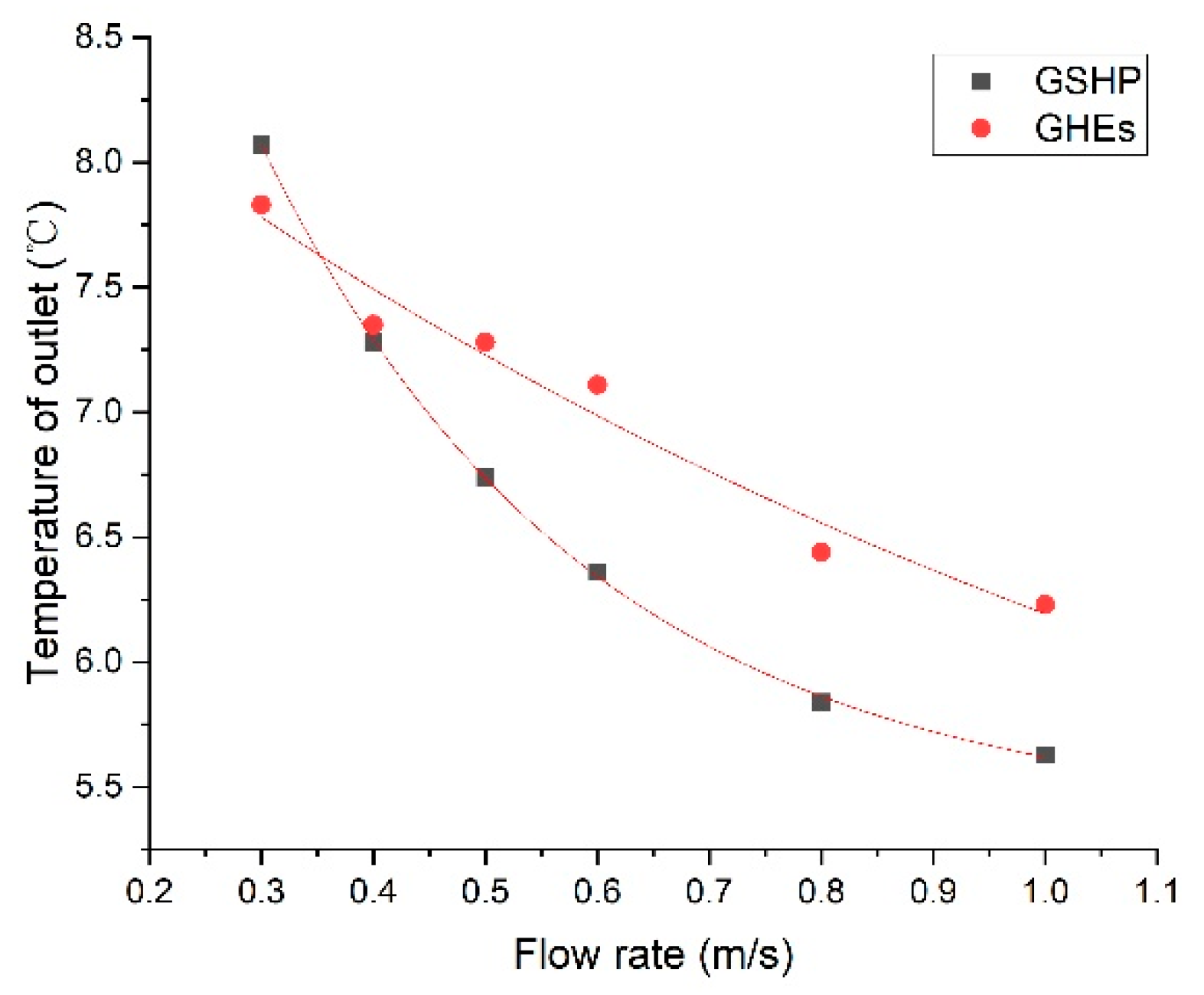
4.3.1. Analysis of Heat Carrier Fluid Flow Rate

Figure 11 shows the relationship between the outlet temperature and the heat carrier fluid flow rate for both GHEs and GSHP systems after 60 days of continuous operation in winter heating mode. This relationship was determined through polynomial fitting. As the flow rate increases, the outlet temperature of the heat carrier fluid noticeably decreases in both systems, reflecting more effective heat extraction.
Specifically, for the GSHP system, when the flow rate reaches 1.0 m/s, the outlet temperature drops to 5.63 °C, only 1.63 °C above the inlet temperature. For the tunnel GHEs, the outlet temperature is 6.23 °C and 2.23 °C above the inlet temperature. These results suggest that while an increased flow rate improves thermal performance in both systems, it leads to diminishing returns beyond a certain threshold.
Notably, the GHEs exhibit higher outlet temperatures across all flow rates, indicating better heating performance. Additionally, their response curve is flatter, meaning the system is less sensitive to flow rate variation compared to GSHPs. This is because energy tunnels rely on long-term heat exchange between the large concrete structure and the surrounding soil. Due to the system’s high thermal mass and relatively slow thermal response, it is less sensitive to fluctuations in the flow rate. This section focuses solely on the winter heating mode, although the trends observed are consistent with those observed under summer cooling conditions, as discussed in previous sections.

4.3.2. Analysis of Heat Carrier Fluid Medium

In both GSHP and energy tunnel systems, various fluids can be used as heat carrier media. While water is the most common, alcohol-based fluids such as ethylene glycol and propylene glycol are frequently used due to their antifreeze capabilities, corrosion resistance, thermal conductivity, and miscibility. In addition, refrigerants such as R-134a and R-407C are often used in GSHP systems because of their thermal conductivity and specific capacity, particularly in heat pump systems [32,33,34].
Among these, ethylene glycol and R-134a were selected in this research to represent alcohol-based and refrigerant-based heat transfer media, respectively. To isolate the effect of fluid properties on system performance, this section focuses solely on the energy tunnel configuration, which has already been shown to outperform the GSHP system in the earlier comparisons.
Figure 12 presents the outlet temperature trends when ethylene glycol is used in the tunnel GHEs during 60-day continuous loading. In winter (Figure 12a), the outlet temperature reached an extremum at approximately 80 h and converged after 500 h, ultimately stabilizing at 6.68 °C. In summer (Figure 12b), the fluid reached a stable outlet temperature of 24.32 °C after a similar convergence period. Throughout these loading processes, the heat exchange segments extracted shallow geothermal energy from the environment, serving as a cooling source.
The results follow similar thermal patterns observed with water but with slightly lower heat transfer efficiency, which is reflected in the total heat exchange values (see Table 5).
Figure 13 shows the results for R-134a. In winter, the outlet temperature stabilized at 10.511 °C after 500 h, while in summer, the outlet temperature converged at 18.911 °C. These values indicate that R-134a exchanged significantly more thermal energy than water or ethylene glycol due to its higher specific heat capacity and thermal conductivity. As shown in Table 5, R-134a yielded the highest total heat transfer in both the heating and cooling scenarios.
Table 5 summarizes the outlet temperatures and total heat transfer values for all three fluids (ethylene glycol, R-134a, and water). The tunnel heat exchanger with R-134a achieved the best performance, delivering 3.88 kW in summer and 3.85 kW in winter. In contrast, ethylene glycol recorded the lowest thermal output, with 1.56 kW and 1.25 kW, respectively. These findings clearly demonstrate that fluid selection significantly influences heat exchange efficiency. The refrigerant-based medium R-134a exhibits the highest heat transfer efficiency in both winter and summer compared to water and ethylene glycol, while the alcohol-based medium ethylene glycol shows the lowest heat transfer performance.

5. Conclusions

In this study, the shield tunnel segments 179 and 180 of the Torino Metro Line 1 in Italy are taken as the engineering background. Focusing on the thermal–hydraulic (TH) coupling behavior of energy tunnels, a three-dimensional finite element model was developed using the COMSOL Multiphysics simulation platform. Comparative simulations were conducted to evaluate the heat transfer performance of energy tunnels and conventional ground source heat pump (GSHP) systems using different types of heat carrier fluids at different flow rates. The main conclusions are as follows:
(1)
A thermal–hydraulic coupled finite element model was successfully established and validated.
The model was constructed based on physical fields including solid heat conduction, porous media seepage, and non-isothermal fluid flow. The simulation results were validated against Barla’s measured data, with an outlet temperature error of only 0.59% in winter and 9.4% in summer. The overall curve trends showed good agreement, confirming the model’s accuracy and reliability in representing thermal–hydraulic coupling heat transfer behavior.
(2)
Under the same conditions, the heat transfer performance of energy tunnels is superior to that of conventional GSHP systems.
Comparative analysis indicates that the energy tunnel system exhibits better heat exchange performance in both the winter and summer scenarios, especially under long-term loading conditions. The outlet temperature of the heat carrier fluid is more stable, and the system shows lower sensitivity to flow rate variations, indicating better operational stability and environmental adaptability.
(3)
The type of heat carrier fluid significantly affects heat transfer performance, with R-134a showing the best overall results.
In the comparative simulations of different carrier fluids, specifically water, ethylene glycol, and R-134a, R-134a demonstrated the highest total heat absorption—3.88 kW in winter and 3.85 kW in summer—significantly outperforming ethylene glycol (1.25 kW and 1.56 kW) and water. This indicates the superior thermal properties and heat exchange efficiency of R-134a. However, despite its thermal advantages, its environmental impact, economic cost, and system integration complexity should be carefully considered in practical applications.
This paper further expands on Barla’s research, although due to the scarcity of energy tunneling engineering projects and the assumptions made when calculating consumption, the conclusions of this paper may be slightly different from actual engineering outcomes. However, the basic rules are generally consistent.
In summary, energy tunnels, as innovative systems that integrate underground infrastructure with shallow geothermal energy utilization, exhibit promising application potential. The thermal–hydraulic coupled simulation model established in this study offers the first integrated comparison of energy tunnel and GSHP system performance under varying fluid conditions, providing a validated modeling framework to support energy tunnel integration with urban infrastructure. The findings offer useful references for future research involving thermal–hydraulic–mechanical (THM) multi-field coupling, experimental validation of material parameters, and the integration of energy tunnels with active control strategies for district heating and cooling in urban underground infrastructure.

Author Contributions

Conceptualization, methodology, software M.Y. and P.L.; validation, formal analysis, data curation and investigation, Z.W.; writing—original draft preparation, and writing—review and editing, M.Y., P.L. and Z.W. All authors have read and agreed to the published version of the manuscript.

Funding

This research received no external funding.

Data Availability Statement

Data available on request due to restrictions.

Conflicts of Interest

The authors declare no conflict of interest.

References

  1. Rui, Y.; Yin, M. Finite element modeling of thermo-active diaphragm walls. Front. Struct. Civ. Eng. 2020, 14, 646–663. [Google Scholar] [CrossRef]
  2. Yin, M.; Rui, Y. Investigation of long-term behaviour of thermal wall by finite element analysis. Soils Found. 2019, 59, 1182–1192. [Google Scholar] [CrossRef]
  3. Rui, Y.; Soga, K. Thermo-hydro-mechanical coupling analysis of a thermal pile. Proc. Inst. Civ. Eng.-Geotech. Eng. 2019, 172, 155–173. [Google Scholar] [CrossRef]
  4. Rui, Y.; Yin, M. Investigations of pile–soil interaction under thermo-mechanical loading. Can. Geotech. J. 2018, 55, 1016–1028. [Google Scholar] [CrossRef]
  5. Rui, Y.; Yin, M. Thermo-hydro-mechanical coupling analysis of a thermo-active diaphragm wall. Can. Geotech. J. 2018, 55, 720–735. [Google Scholar] [CrossRef]
  6. Zhu, J.; Hu, K.; Lu, X.; Huang, X.; Liu, K.; Wu, X. A review of geothermal energy resources, development, and applications in China: Current status and prospects. Energy 2015, 93, 466–483. [Google Scholar] [CrossRef]
  7. Haehnlein, S.; Bayer, P.; Blum, P. International legal status of the use of shallow geothermal energy. Renew. Sustain. Energy Rev. 2010, 14, 2611–2625. [Google Scholar] [CrossRef]
  8. Xu, Y.-S.; Wang, X.-W.; Shen, S.-L.; Zhou, A. Distribution characteristics and utilization of shallow geothermal energy in China. Energy Build. 2020, 229, 110479. [Google Scholar] [CrossRef]
  9. Hou, J.; Cao, M.; Liu, P. Development and utilization of geothermal energy in China: Current practices and future strategies. Renew. Energy 2018, 125, 401–412. [Google Scholar] [CrossRef]
  10. Rui, Y.; Garber, D.; Yin, M. Modelling ground source heat pump system by an integrated simulation programme. Appl. Therm. Eng. 2018, 134, 450–459. [Google Scholar] [CrossRef]
  11. Sarbu, I.; Sebarchievici, C. General review of ground-source heat pump systems for heating and cooling of buildings. Energy Build. 2014, 70, 441–454. [Google Scholar] [CrossRef]
  12. Luo, J.; Rohn, J.; Xiang, W.; Bertermann, D.; Blum, P. A review of ground investigations for ground source heat pump (GSHP) systems. Energy Build. 2016, 117, 160–175. [Google Scholar] [CrossRef]
  13. Brandl, H. Geothermal geotechnics for urban undergrounds. Procedia Eng. 2016, 165, 747–764. [Google Scholar] [CrossRef]
  14. Brandl, H. Energy foundations and other thermo-active ground structures. Géotechnique 2006, 56, 81–122. [Google Scholar] [CrossRef]
  15. Adam, D.; Markiewicz, R. Energy from earth-coupled structures, foundations, tunnels and sewers. Géotechnique 2009, 59, 229–236. [Google Scholar] [CrossRef]
  16. Zhang, G.; Xia, C.; Sun, M.; Zou, Y.; Xiao, S. A new model and analytical solution for the heat conduction of tunnel lining ground heat exchangers. Cold Reg. Sci. Technol. 2013, 88, 59–66. [Google Scholar] [CrossRef]
  17. Makasis, N.; Narsilio, G.A. A case study on the application of energy tunnels in Sydney, Australia. In Challenges and Innovations in Geomechanics: Proceedings of the 16th International Conference of IACMAG-Volume 2; Springer: Cham, Switzerland, 2021; pp. 1077–1084. [Google Scholar]
  18. Buhmann, P.; Moormann, C.; Westrich, B.; Pralle, N.; Friedemann, W. Tunnel geothermics—A German experience with renewable energy concepts in tunnel projects. Geomech. Energy Environ. 2016, 8, 1–7. [Google Scholar] [CrossRef]
  19. Lee, C.; Park, S.; Choi, H.-J.; Lee, I.-M.; Choi, H. Development of energy textile to use geothermal energy in tunnels. Tunn. Undergr. Space Technol. 2016, 59, 105–113. [Google Scholar] [CrossRef]
  20. Islam, M.S.; Fukuhara, T.; Watanabe, H.; Nakamura, A. Horizontal U-tube road heating system using tunnel ground heat. J. Snow Eng. Jpn. 2006, 22, 229–234. [Google Scholar] [CrossRef]
  21. Franzius, J.N.; Pralle, N. Turning segmental tunnels into sources of renewable energy. In Proceedings of the Institution of Civil Engineers-Civil Engineering, 2011; Thomas Telford Ltd.: London, UK, 2011; pp. 35–40. [Google Scholar]
  22. Barla, M.; Baralis, M.; Insana, A.; Aiassa, S.; Antolini, F.; Vigna, F.; Azzarone, F.; Marchetti, P. On the thermal activation of Turin metro Line 2 tunnels. In Challenges and Innovations in Geomechanics: Proceedings of the 16th International Conference of IACMAG-Volume 2; Springer: Cham, Switzerland, 2021; pp. 1069–1076. [Google Scholar]
  23. Carteni, A.; Cascetta, F. Particulate matter concentrations in a high-quality rubber-tyred metro system: The case study of Turin in Italy. Int. J. Environ. Sci. Technol. 2018, 15, 1921–1930. [Google Scholar] [CrossRef]
  24. Baralis, M.; Barla, M.; Bogusz, W.; Di Donna, A.; Ryżyński, G.; Żeruń, M. Geothermal potential of the NE extension Warsaw (Poland) metro tunnels. Environ. Geotech. 2018, 7, 282–294. [Google Scholar] [CrossRef]
  25. Zhang, G.; Xia, C.; Yang, Y.; Sun, M.; Zou, Y. Experimental study on the thermal performance of tunnel lining ground heat exchangers. Energy Build. 2014, 77, 149–157. [Google Scholar] [CrossRef]
  26. Barla, M.; Di Donna, A.; Perino, A. Application of energy tunnels to an urban environment. Geothermics 2016, 61, 104–113. [Google Scholar] [CrossRef]
  27. Di Donna, A.; Barla, M. The role of ground conditions on energy tunnels’ heat exchange. Environ. Geotech. 2016, 3, 214–224. [Google Scholar] [CrossRef]
  28. Magdy, A.; Ogunleye, O.; Mroueh, H.; Di Donna, A.; Singh, R.M. A review of exploiting shallow geothermal energy through tunnels: Current status and future prospects. Renew. Energy 2024, 238, 121958. [Google Scholar] [CrossRef]
  29. Zhang, G.; Cao, Z.; Xiao, S.; Guo, Y.; Li, C. A promising technology of cold energy storage using phase change materials to cool tunnels with geothermal hazards. Renew. Sustain. Energy Rev. 2022, 163, 112509. [Google Scholar] [CrossRef]
  30. Shafagh, I.; Rees, S.; Loveridge, F. Investigations into thermal resistance of tunnel lining heat exchangers. In E3S Web of Conferences, 2020; EDP Open: Paris, France, 2020. [Google Scholar]
  31. Barla, M.; Di Donna, A.; Insana, A. A novel real-scale experimental prototype of energy tunnel. Tunn. Undergr. Space Technol. 2019, 87, 1–14. [Google Scholar] [CrossRef]
  32. Rasti, M.; Aghamiri, S.; Hatamipour, M.-S. Energy efficiency enhancement of a domestic refrigerator using R436A and R600a as alternative refrigerants to R134a. Int. J. Therm. Sci. 2013, 74, 86–94. [Google Scholar] [CrossRef]
  33. Lee, J.; Bae, S.; Bang, K.; Kim, M. Experimental and numerical research on condenser performance for R-22 and R-407C refrigerants. Int. J. Refrig. 2002, 25, 372–382. [Google Scholar] [CrossRef]
  34. Atwood, T.; Hughes, H.M. Refrigerants and energy efficiency. Int. J. Refrig. 1990, 13, 270–273. [Google Scholar] [CrossRef]
Figure 1. The 3D layout of GHEs in the tunnel lining.
Buildings 15 02704 g001
Figure 2. The 3D FEM model of the energy tunnel.
Buildings 15 02704 g002
Figure 3. The 3D FEM model.
Buildings 15 02704 g003
Figure 4. The outlet temperature of the GHEs in (a) winter and (b) summer.
Buildings 15 02704 g004
Figure 5. Darcy’s law flow field diagram of different air velocities in the tunnel.
Buildings 15 02704 g005
Figure 6. A cross-sectional view of the formation temperature field: (a) in winter; (b) in summer.
Buildings 15 02704 g006
Figure 7. The 3D geometric model of the U-shaped GSHP.
Buildings 15 02704 g007
Figure 8. One-dimensional U-shaped GSHP model.
Buildings 15 02704 g008
Figure 9. GSHP tunnel model.
Buildings 15 02704 g009
Figure 10. Non-isothermal temperature field in heat exchanger pipe: (a) winter scenario; (b) summer scenario.
Buildings 15 02704 g010
Figure 11. The outlet temperature of the heat carrier fluid versus the flow rate for GSHP system and energy tunnel GHEs in the winter heating mode after 60 days of operation.
Buildings 15 02704 g011
Figure 12. Outlet temperature profile of energy tunnel GHEs with ethylene glycol as heat carrier fluid: (a) in winter; (b) in summer.
Buildings 15 02704 g012
Figure 13. Outlet temperature profile of energy tunnel GHEs with R-134a as heat carrier fluid: (a) in winter; (b) in summer.
Buildings 15 02704 g013
Table 1. Physical parameters of heat exchange piping.
ParameterSymbolUnitSize
Diameter d e x t ¯ mm24
Thicknesstmm2
Velocity of Flowv m · s 1 0.4
Thermal Conductivity of Flowkf W · m 1 · K 1 0.58
Thermal Conductivity of Concrete k w a l l W · m 1 · K 1 0.38
Thermal Capacity of Flow ρ w c w M j · m 3 · K 1 4.2
Table 2. Physical parameters of concrete and soil.
MaterialPropertyUnitSize
SoilPorosity10.25
Density k g · m 3 2202.6
Thermal Conductivity of Soil W · m 1 · K 1 2.8
Thermal Conductivity of Flow W · m 1 · K 1 0.65
Thermal Capacity of Soil M j · m 3 · K 1 2.0
Thermal Capacity of Flow M j · m 3 · K 1 4.2
Transverse Heat Dispersion Coefficientm3.1
Longitudinal Heat Dispersion Coefficientm0.3
ConcreteThermal Conductivity of Concrete W · m 1 · K 1 2.3
Thermal Capacity of Concrete M j · m 3 · K 1 2.19
Density k g · m 3 2300
Table 3. Comparison of numerical simulation results.
NameSeasonQ (W)Qs (W/m2)
Results of Barla [20]Winter1.6752.76
Summer2.3473.87
Results of this studyWinter1.6655.56
Summer2.1270.95
Table 4. Simulation results comparing the thermal performance of the energy tunnel heat exchanger and a ground source heat pump heat exchanger under winter and summer conditions.
NameSeasonOutlet Temperature (°C)Q (W)
GHEsWinter7.550.05
Summer23.000.07
GSHPWinter6.250.06
Summer23.160.07
Table 5. Outlet temperatures of GHEs with different heat carrier fluids in winter and summer.
Fluid MediumSeasonOutlet Temperature (°C)Q (KW)
WaterWinter7.551.66
Summer23.002.12
Ethylene glycolWinter6.681.25
Summer24.321.56
R-134aWinter10.513.85
Summer18.913.88
Disclaimer/Publisher’s Note: The statements, opinions and data contained in all publications are solely those of the individual author(s) and contributor(s) and not of MDPI and/or the editor(s). MDPI and/or the editor(s) disclaim responsibility for any injury to people or property resulting from any ideas, methods, instructions or products referred to in the content.

