Article

Near-Surface-Mounted CFRP Ropes as External Shear Reinforcement for the Rehabilitation of Substandard RC Joints

by
George Kalogeropoulos
1,*,
Georgia Nikolopoulou
1,
Evangelia-Tsampika Gianniki
1,
Avraam Konstantinidis
2 and
Chris Karayannis
1
1
Laboratory of Reinforced Concrete and Masonry Structures, Department of Civil Engineering, Aristotle University of Thessaloniki, 54124 Thessaloniki, Greece
2
Laboratory of Engineering Mechanics, Department of Civil Engineering, Aristotle University of Thessaloniki, 54124 Thessaloniki, Greece
*
Author to whom correspondence should be addressed.
Buildings 2025, 15(14), 2409; https://doi.org/10.3390/buildings15142409
Submission received: 6 June 2025 / Revised: 30 June 2025 / Accepted: 7 July 2025 / Published: 9 July 2025

Abstract

The effectiveness of an innovative retrofit scheme using near-surface-mounted (NSM) X-shaped CFRP ropes for the strengthening of substandard RC beam–column joints was investigated experimentally. Three large-scale beam–column joint subassemblages were constructed with poor reinforcement details. One specimen was subjected to cyclic lateral loading, exhibited shear failure of the joint region and was used as the control specimen. The other specimens were retrofitted and subsequently subjected to the same history of incremental lateral displacement amplitudes with the control subassemblage. The retrofitting was characterized by low labor demands and included wrapping of NSM CFPR-ropes in the two diagonal directions on both lateral sides of the joint as shear reinforcement. Single or double wrapping of the joint was performed, while weights were suspended to prevent the loose placement of the ropes in the grooves. A significant improvement in the seismic performance of the retrofitted specimens was observed with respect to the control specimen, regarding strength and ductility. The proposed innovative scheme effectively prevented shear failure of the joint by shifting the damage in the beam, and the retrofitted specimens showed a more dissipating hysteresis behavior without significant loss of lateral strength and axial load-bearing capacity. The cumulative energy dissipation capacity of the strengthened specimens increased by 105.38% and 122.23% with respect to the control specimen.

1. Introduction

The devastating social and economic effects of strong seismic events of the last 60 years worldwide have demonstrated the imperative necessity for improving the inelastic behavior of existing substandard reinforced concrete (RC) structures. It is essential to secure damage limitation and control, as well as to preserve structural integrity during future earthquakes. Hence, enhancing the effectiveness and suitability of both conventional and, primarily, innovative techniques for retrofitting existing RC structures not conforming to the requirements of modern seismic design codes has emerged as a scientific field of paramount importance.
In recent years, modern materials such as fiber-reinforced polymers (FRPs) in various forms (sheets, laminates and rebars) have increasingly been used for the earthquake-resistant rehabilitation of existing RC structures [1,2,3,4,5,6,7,8,9,10,11]. These materials are used especially when the essential aim is the improvement of energy dissipation capacity and ductility of the strengthened structural members. A comprehensive literature review with an extended data base including RC beam–column joints strengthened with FRPs subjected to seismic loading was presented by Pohoryles et al. [7]. Despite the ease of application of the FRPs with respect to more conventional strengthening schemes, such as RC jackets or shotcrete jackets, the particularly high tensile strength of these composite materials is rarely fully exploited. This is due to the early detachment of the strengthening material from the concrete and the consequential failure of the anchorage. Mostofinejad and Akhlaghi investigated the efficiency of an innovative anchorage method for CFRP sheets used to strengthen beam–column joints [10,11]. In addition, the effectiveness of near-surface-mounted (NSM) CFRP plastic sheets or ropes was experimentally investigated [12,13,14,15].
One of the drawbacks of the use of composite materials such as CFRP sheets is their inability to form a continuous closed jacket for the strengthening of RC beams. Even more important is their inability to effectively confine the beam–column joint region, due to the interference of slabs and transverse beams. Hybrid strengthening schemes, combining the local use of conventional RC or steel-fiber-reinforced concrete jackets in the joint region along with CFRP sheets for strengthening columns and beams, were proposed by Tsonos. These schemes aimed to improve the retrofitting of beam–column joints when using CFRP sheets [4]. Ecran, Arisoy and Ertem experimentally investigated the seismic behavior of RC beam–column joints strengthened with CFRP sheets externally and steel bars internally and assessed the improvement in deformation capacity and strength [16].
Recently, the effectiveness of carbon-fiber-reinforced polymer ropes (CFRP ropes) when used as shear reinforcement was investigated [17,18]. Golias et al. [19] proposed a retrofit scheme for exterior beam–column joints with CFRP diagonal ties (rope connections) passing through the joint area. The effectiveness of the additional bars and ropes which were used as shear reinforcement on the overall seismic performance of the tested joint specimens was evaluated. Furthermore, Karayannis and Golias [20,21] and Karayannis, Golias and Kalogeropoulos [22] used CFRP ropes for the strengthening of full-scale exterior RC beam–column joint specimens with particularly favorable and promising results regarding the improvement achieved in the ductility of the subassemblages. According to the retrofit technique applied, the CFRP ropes were used as near-surface-mounted (NSM) shear reinforcement, which should be adequate to effectively restrict shear deformation of the joint region.
In the case of RC beams with L- or T-shaped cross-sections, the most common retrofit interventions include the use of externally bonded FRP sheets on three sides of the beam’s web, where brittle debonding failures predominate. Alternatively, NSM CFRP ropes can be used to effectively confine the beams by forming closed ties with the composite materials [23]. A strengthening technique for upgrading the seismic response of reinforced concrete (RC) deep beams without steel stirrups using CFRP ropes as the only transverse shear reinforcement was investigated experimentally by Chalioris et al. [18].
The experience gained from previous works was used to further improve the proposed retrofitting scheme for beam–column joints in the present research. This improvement includes the application of the NSM CFRP ropes in both diagonal directions of the joint region under tension. This allows the joint concrete core to remain intact and inhibit any shear cracking during seismic loading. Furthermore, the use of weights hanging from the ends of the ropes to prevent their loose placement ensures tight application and higher effectiveness of the technique.

2. Materials and Methods

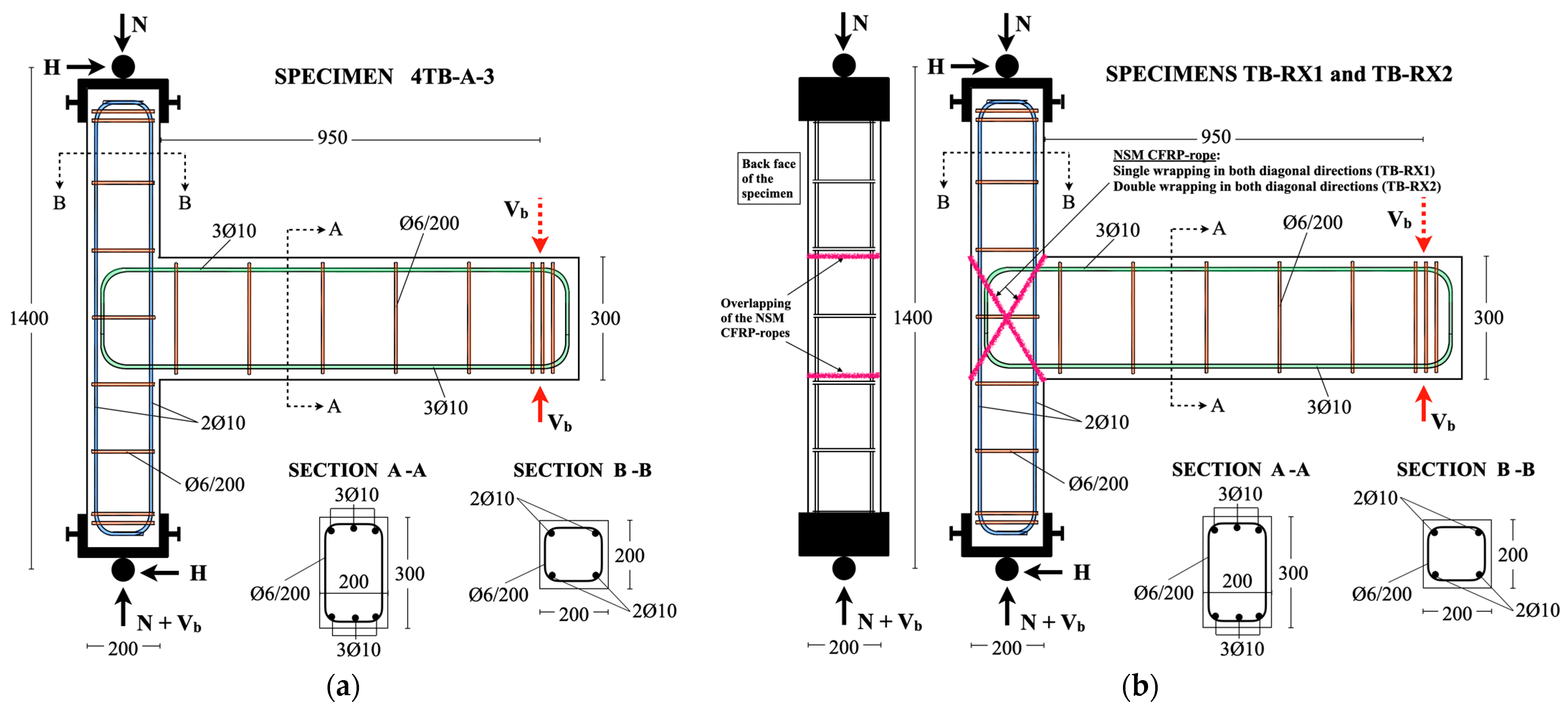
2.1. Construction of the Beam–Column Joint Subassemblages

The seismic behavior of structural members constituting the load-bearing system critically affects the overall seismic performance of RC structures. For this reason, based on the capacity design approach, the structural members of modern RC structures are designed to possess increased ductility and deformation capacity at the locations where seismic damage is expected to occur with the formation of plastic hinges. Moreover, the development of brittle failure mechanisms such as reinforcement slipping or concrete shear cracking should be avoided, to ensure the flexural response and energy-dissipating hysteresis performance. However, the existing substandard RC structures were not designed according to the philosophy of hierarchically developed damage and damage control. Admittedly, a significant number of serious design flaws and structural deficiencies are found in existing RC structures built prior to the 1960s–1970s, being responsible for the rapid degradation of their overall hysteresis performance. Such flaws include, for example, the use of plain steel reinforcement and low-compression-strength concrete, the inadequacy of transverse reinforcement, the insufficient length of lap splices and reinforcement anchorage, etc. These parameters deteriorate the cyclic performance causing a devastating impact on the structural integrity [24]. Hence, it is particularly important to thoroughly study the seismic behavior of existing substandard RC structures and understand the dependence of developing failure mechanisms on the design parameters. After all, the retrofit schemes proposed, in order to be effective, need to improve the cyclic behavior of the strengthened structures and prevent brittle behavior during future strong earthquakes.
A retrofit scheme simple in application, with innovative materials and minimal disturbance to the structure’s operation, would be, under the right circumstances, particularly competitive among other more conventional strengthening systems including increased labor and cost demands. Thus, the strengthening scheme proposed herein, which includes the use of NSM CFPR ropes in both diagonal directions of the joint as shear reinforcement, is indisputably superior to the conventional FRP-wrapping technique. This is because effective anchorage of the CFRP ropes is possible even in the case of interior joints connecting beams on all their sides. The latter, however, is not true when CFRP sheets are used to wrap the joint region.
The effectiveness of NSM CFPR ropes used for the strengthening of beam–column joints was recently experimentally investigated [17,21,22], providing useful and optimistic results. However, the proposed retrofit scheme includes the application of the CFRP ropes in both diagonal directions of the joint region under tension, to allow for the immediate activation of the ropes as shear reinforcement, prior to the formation of diagonal cracks and dilation of the joint’s concrete core. Three similar large-scale (1:2) exterior beam–column joint subassemblages were designed and constructed with poor reinforcement details, representative of structural members found in substandard RC structures. In particular, the specimens had plain steel longitudinal rebars with f y = 374   ( M P a ) and ties of plain steel with f y w = 263.5   M P a spaced at 200 mm, while the concrete had a low compressive strength of approximately f c = 7   M P a , measured by using 150 × 300 mm cylinder compression tests (see Table 1). Reinforcement details and sectional dimensions of the specimens are illustrated in Figure 1. The specimens were designated 4TB-A-3, TB-RX1 and TB-RX2, with T and B referring to the beam top and bottom rebars, respectively, which were anchored with 90° hooks in the joint region, and the letter A corresponds to the shear span/depth of the beam ratio, which is equal to 3.89 [24]. The number “4” represents the number of the column longitudinal rebars, and the additional number “3” indicates that the control subassemblage was subjected to a different displacement history which included three cycles per displacement step. The letter R indicates the use of CFRP ropes for the retrofitting, and X refers to the way the ropes were applied (in both diagonal directions (X) of the joint). Numbers 1 and 2 refer to the wrapping of the joint region with the ropes. The specimens were subjected to the same history of incremental lateral displacements, which included three cycles for each displacement step (see Figure 2 and Figure 3). The original subassemblage, 4TB-A-3, was used as the control specimen and was subjected to earthquake-type loading without being previously retrofitted. Specimens TB-RX1 and TB-RX2 were strengthened with NSM CFRP ropes used as shear reinforcement by wrapping both diagonal directions of the joint region one and two times, respectively. Subsequently, both retrofitted subassemblages were subjected to the same displacement history as the control specimen, 4TB-A-3, and the hysteresis behavior of all specimens was compared to assess the effectiveness of the proposed retrofit scheme. Furthermore, the seismic behavior of another specimen, 4TB-A (similar to the original one, 4TB-A-3), which was tested in a previous work [24] according to the displacement history shown in Figure 3a (including one cycle per displacement step), was also compared to the hysteresis response of 4TB-A-3, TB-RX1 and TB-RX2 to evaluate the influence of damage accumulation during multiple cycles of seismic loading. It should be mentioned that in the case of subassemblage 4TB-A, the anchorage of the beam’s rebars in the joint included the use of two Ø10 plain steel bars welded transversely near the 90° hook.
Table 1. Reinforcement details and design parameters of the beam–column joint subassemblages.
SpecimenRetrofit TechniqueColumn and Beam RebarsAnchorage of Beam Rebars in the Joint f c
( M P a )
f y
( M P a )
f y w
( M P a )
Σ M R c Σ M R b
* 4TB-A-Column:
4Ø10
Beam:
3Ø10 (top)
3Ø10 (bottom)
90° hook + 2Ø10 plain steel bars welded transversely7.0374
plain steel bars
263.5 plain steel bars1.17
4TB-A-3-90° hook
TB-RX1NSM CFRP rope—
single wrapping in both diagonal directions of the joint
TB-RX2NSM CFRP rope—
double wrapping in both diagonal directions of the joint
* Specimen 4TB-A was tested in a previous work [24].
Figure 1. Reinforcement details and cross-sections of beam–column joint subassemblages. (a) 4TB-A-3 (original) and (b) TB-RX1 and TB-RX2 (strengthened).
Buildings 15 02409 g001
Figure 2. Retrofitting process of beam–column joint subassemblages TB-RX1 and TB-RX2. (a) Formation of trenches; (b) anchorage of the CFRP ropes by overlapping the ends of each rope at the back face of the joint; (c) use of weights to prevent loose placement of the CFRP ropes; (d) view of the applied CFRP ropes after removing the weights; (e) covering of the hardened CFRP ropes with epoxy-based high-performance chemical anchoring adhesive.
Buildings 15 02409 g002aBuildings 15 02409 g002b
Figure 3. Displacement-controlled schedules according to which the earthquake-type loading of beam–column joint subassemblages was performed: (a) specimen 4TB-A [24]; (b) specimens 4TB-A-3, TB-RX1 and TB-RX2.
Buildings 15 02409 g003
The application process of CFRP ropes for the strengthening of the beam–column connections included four steps (see Figure 2):
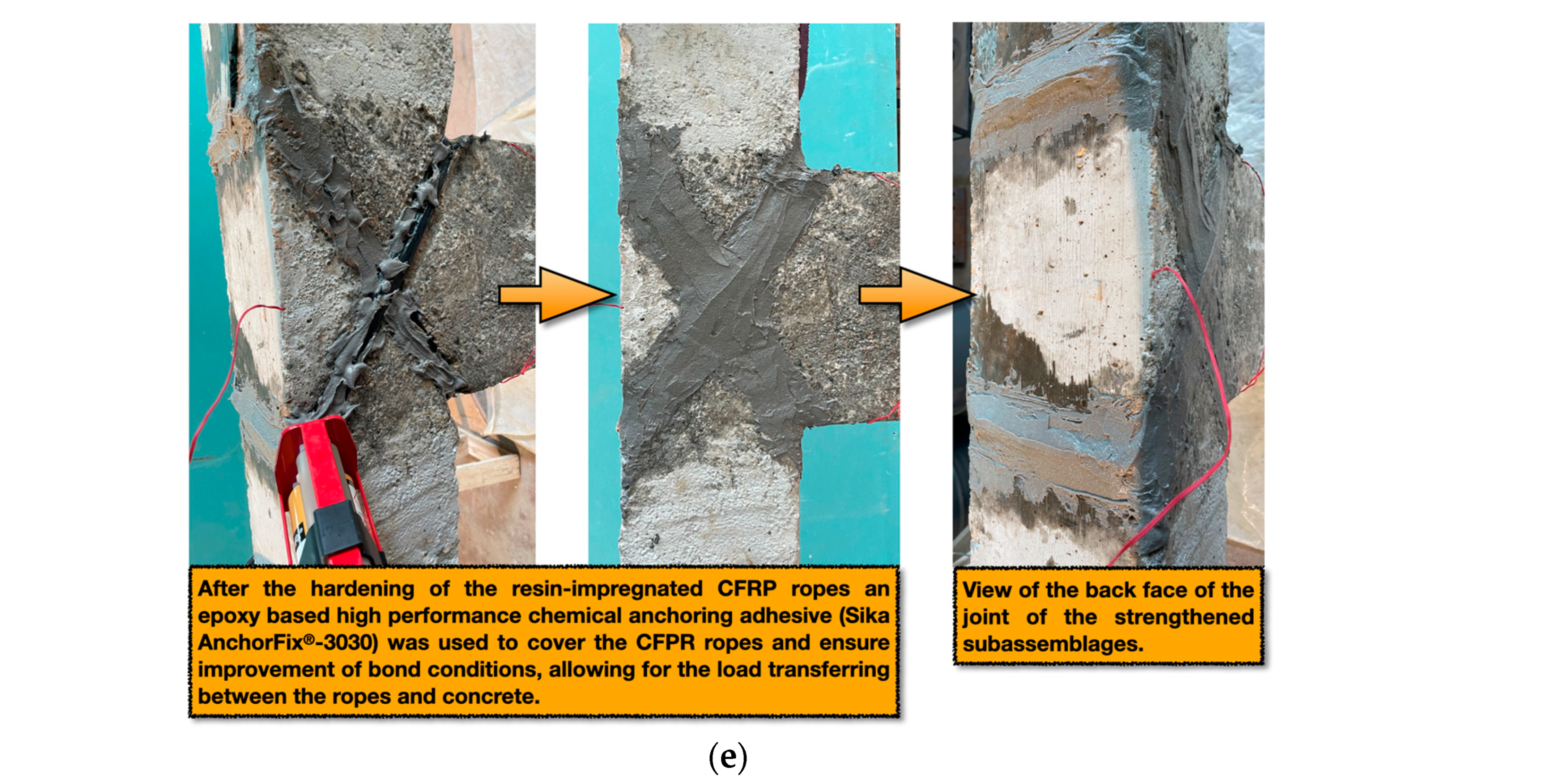
  • Using a grinding wheel, a 1 cm deep trench was formed in the surface around the joint region in both diagonal directions and subsequently cleaned with air pressure (see Figure 2a).
  • Afterwards, each CFRP rope (SikaWrap® FX-50 C) was impregnated with epoxy resin in two compartments (Sikadur® 52 Injection LP), inserted into the groove and applied to the beam–column joint by wrapping it diagonally one or two times in the case of specimens TB-RX1 and TB-RX2, respectively (see Figure 2b).
  • The anchorage of each CFRP rope was achieved by overlapping at the back face of the specimen, while weights were hung from its free ends to prevent the loose application of the rope and ensure that it is tight enough for actively contributing as shear reinforcement of the joint (see Figure 2c,d).
  • After the hardening of the resin-impregnated CFRP ropes, an epoxy-based high-performance chemical anchoring adhesive (Sika AnchorFix®-3030) was used to cover the CFPR ropes and ensure improvement of bond conditions, allowing for the load transferring between the ropes and concrete (see Figure 2e).
All subassemblages were constructed with the capacity design ratio value Σ Μ R c / Σ M R b = 1.17 , which is lower than the minimum required value (1.30) according to Eurocode 8 for ensuring the concentration of seismic damage and the formation of plastic hinges in the beam (see Table 1). Additionally, this was particularly common for structures built prior to the 1960s–1970s period.

2.2. Micro-Tensile Testing Results of the Rope Fibers

A series of tensile experiments were performed using “fibers” extracted from the used unidirectional carbon fiber cord. Prior to the micro-tensile tests, each extracted “fiber” diameter was measured using a LEICA DCM8 Confocal Microscope. It is noted that the extracted “fibers” were still rope-like, with different diameters. The “fiber” diameters were measured as the “macroscopic” diameter of the micro-rope at its thinnest point along its length.
The diameters of a total of 30 micro-ropes were measured this way, with their diameters ranging between 14 and 106 μm. Afterwards, the “fibers” or micro-ropes were subjected to displacement-controlled micro-tension using an Agilent T150 UTM instrument. The strain rate was chosen to be equal to 0.001 s−1 in all tests, and Poisson’s ratio was assumed to be equal to 0.25. From the 30 measurements, 10 failed mainly due to micro-fiber damage at the instrument’s grips. The elastic modulus calculated from the successful tensile tests ranged between 10 and 100 GPa and had a mean value of 38.33 GPa, while the yield stress ranged between 40 and 800 MPa and had a mean value of 210 MPa. The modulus as well as yield stress values are, as expected, lower than the ones of the rope, where for a minimum macroscopic rope of cross-section ≥ 28 mm2 (this cross-section is equivalent to a minimum diameter of 6 mm), a modulus of elasticity of 240 GPa and a yield stress of 4 GPa are reported—enhanced mechanical properties due to the rope-like arrangement of the numerous “fibers” it consists of. It is also noted that in the micro-rope case, the modulus of elasticity was calculated assuming, as mentioned above, a single minimum “macroscopic” diameter, i.e., assuming a single strand, while a “rope modulus of elasticity” [25] was most probably calculated for the case of the macroscopic-stranded wire rope [26]. The calculation of such a “rope modulus of elasticity” [25] for each of the micro-ropes is a very demanding procedure and is left for a future work.

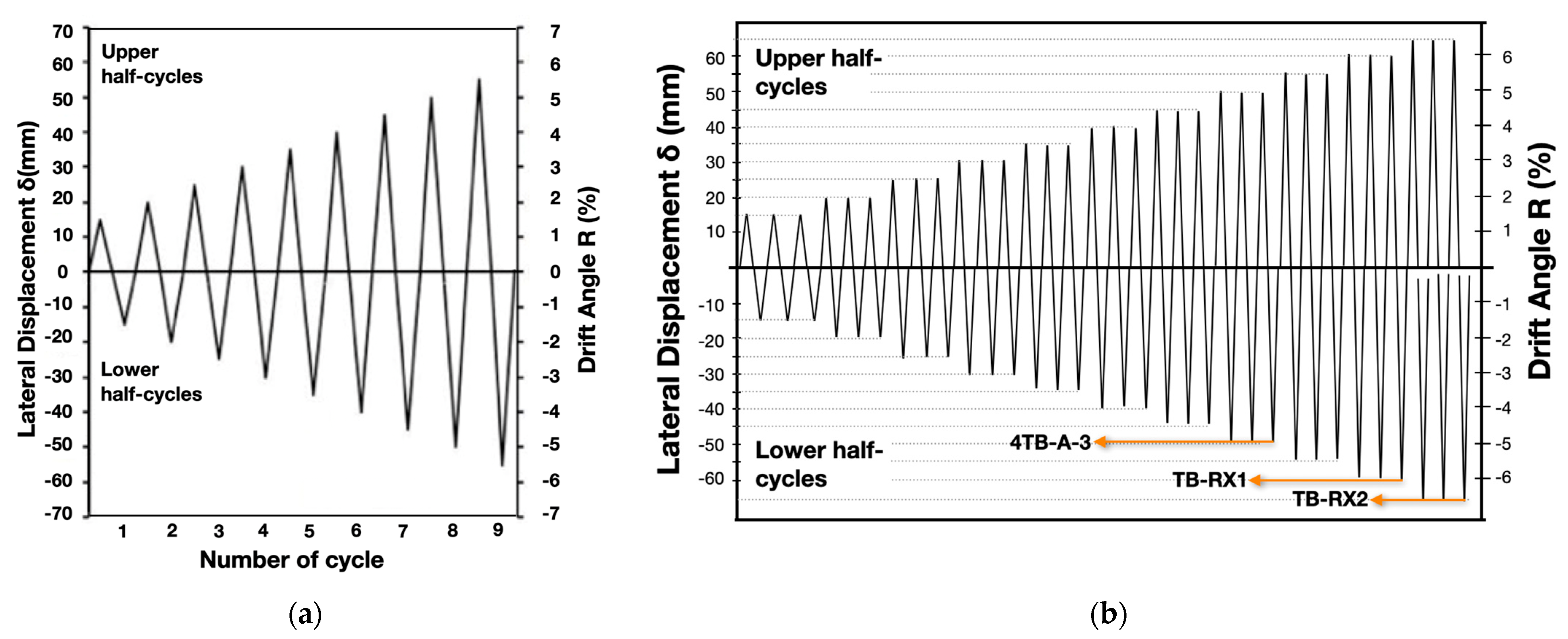
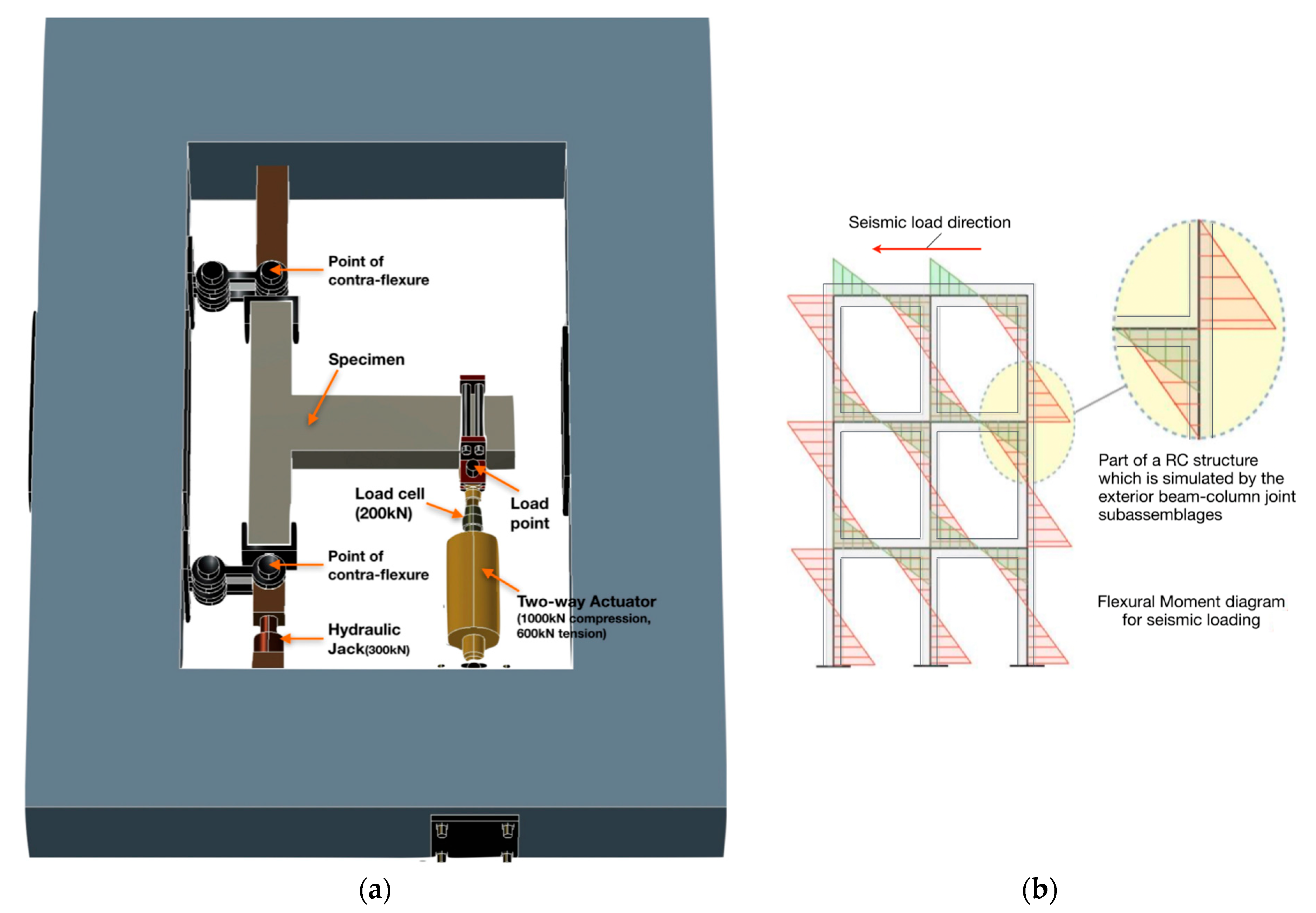
2.3. Seismic Testing of the Beam–Column Joint Subassemblages

Seismic tests were conducted in the test setup located at the Laboratory of Reinforced Concrete and Masonry Structures of the Aristotle University of Thessaloniki (see Figure 4a). Each specimen represented the part of an exterior beam–column connection of an RC building between the points of contra-flexure at the middle of the column height and the beam length, where the flexural moment from the seismic loading is almost zero. Specific arrangements connected to the reaction frame and to the free ends of the subassemblages by hinges were used to simulate the inflection points of the columns. Thus, the horizontal and vertical displacement of the columns’ free ends were restrained, while they were able to rotate freely. The seismic loading of the subassemblages was performed under constant axial loading of the columns equal to 150 kN, while the beam’s free end for each specimen was subjected to a large number of incremental amplitudes of inelastic lateral displacement reversals, according to the displacement-controlled schedules illustrated in Figure 3a,b. The axial load was applied to the columns using a hydraulic jack. The lateral displacements of the beam’s free end for each specimen were applied by a two-way actuator, while the resisting shear force was measured by a load cell (see Figure 4a). A calibrated linear variable differential transducer (LVDT) was used to measure the load-point displacement. A test specimen similar to the examined subassemblages was used to determine the steps of the displacement-controlled schedule. It was first loaded up to its yield displacement, determined by the point with a significant decrease in stiffness in the respective resisted shear force versus displacement graph, and was further verified using strain gages attached to the steel rebars, which documented yielding of the beam’s rebars at the juncture with the joint. The loading was subsequently continued in the same direction (upper push half-cycle) up to 1.5 times the yield displacement, and the specimen was then loaded in the opposite direction (upper and lower pull half-cycle) to the same lateral displacement. For subassemblage 4TB-A, which was tested in a previous work [24], after the first cycle of loading, the maximum displacement of each subsequent cycle was incremented by 0.5 times the yield displacement [27,28,29] (see Figure 3a). For specimens 4TB-A-3, TB-RX1 and TB-RX2 the displacement steps were the same as for specimen 4TB-A. However, three cycles of reversed lateral displacement were performed for each step (see Figure 4b). Due to the pseudo-static conditions of the earthquake-type loading, the applied strain rate was lower than that corresponding to actual seismic events, resulting in somewhat lower strengths exhibited by the subassemblages [30,31,32].

3. Experimental Results

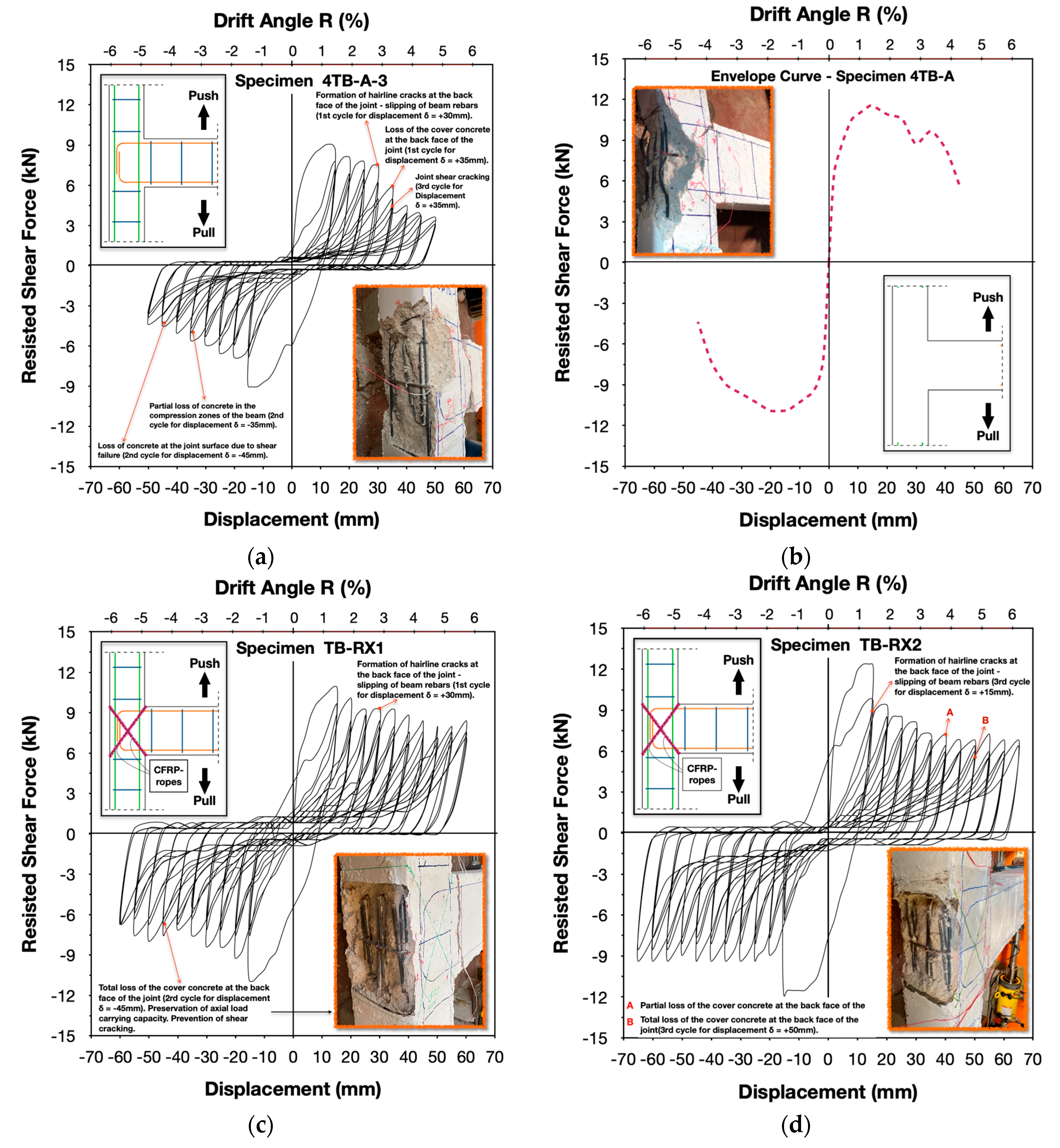
3.1. Hysteresis Behavior of the Beam–Column Joint Subassemblages

A thorough analysis and documentation of the seismic performance of the beam–column joint specimens was performed, based on the experimentally acquired data and comprehensive interpretation of the failure mode of the subassemblages. The evaluation of the overall inelastic cyclic response of each specimen was documented by the exhibited changes in lateral strength, peak-to-peak stiffness, energy dissipation capacity, ductility and viscous damping (see Figure 9, Figure 10, Figure 11, Figure 12, Figure 13 and Figure 14). Furthermore, the propagation of cracking and damage evolution was explained based on the developed failure mechanisms for each subassemblage (see Figure 5, Figure 6, Figure 7 and Figure 8). Subsequently, the hysteresis performance of the strengthened specimens TB-RX1 and TB-RX2 was compared and evaluated with respect to the cyclic behavior of the control subassemblage 4TB-A-3 to assess the effectiveness of the applied retrofit schemes. Comparison of the seismic behavior of specimens 4TB-A-3, TB-RX1 and TB-RX2 was also performed with respect to subassemblage 4TB-A, which was subjected to a displacement-controlled history of one cycle per displacement step. This led to determining the influence of damage accumulation during more cycles of loading and the influence of the improved anchorage conditions when additional rebars are welded transversely to the beam reinforcement before the 90° hook in the joint region.

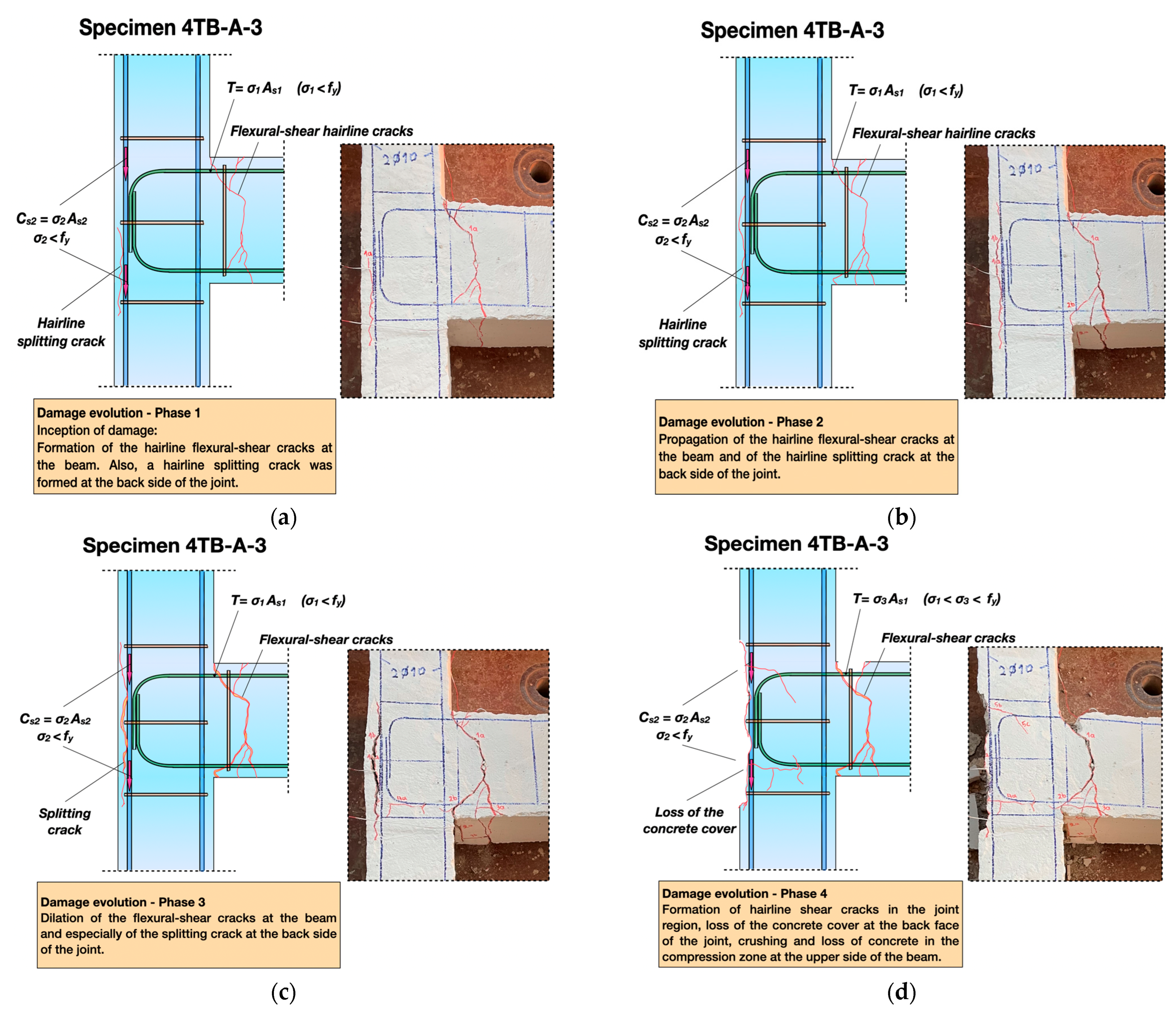
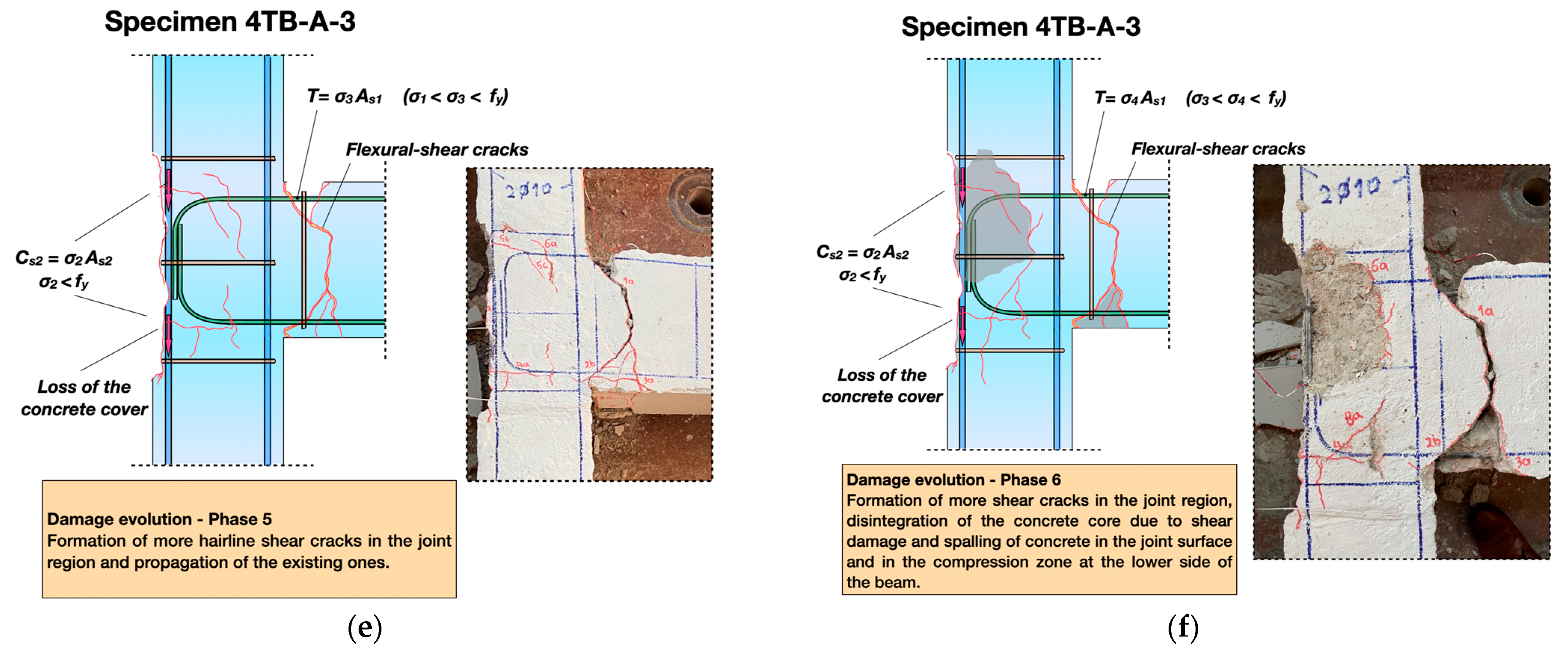
3.1.1. Original Subassemblage 4TB-A-3

The beam’s top and bottom longitudinal rebars of the original subassemblage 4TB-A-3 were anchored into the beam–column joint region with 90° hooks. Also, one tie was provided in the joint, which contributed to holding the beam reinforcement in place after the loss of the concrete cover in the rear face of the joint (see Figure 1). Damage initiation comprised the formation of hairline flexural and flexural-shear cracks in the beam during the first upper and lower a-half-cycles (1a) of the earthquake-type loading (drift angle R = 1.43%). Moreover, a splitting crack was formed at the back side of the joint along the vertical hook segments of the beam reinforcement (after the 90° curvature) (see Figure 5a). The latter resulted from the poor bonding between the plain steel reinforcing bars of the beam and the surrounding concrete, which were further degraded rapidly at the location of the flexural crack in the beam, causing slipping of the beam rebars. As a result, the bars tended to straighten, and, thus, the 90° hook end was pushed out of the joint slightly, obstructed only by the joint tie. This splitting crack propagated along the joint height during the next (second) cycle, 1b, (b-cycle for R = 1.43%). Subsequently, only minor evolution of damage was observed in the beam of the specimen, while the splitting crack at the back side of the joint region gradually dilated until the cover concrete at the rear face of the joint was lost during cycle 5a (peak displacement equal to ±35 mm, R = 3.33%) (see Figure 5b,c). Partial concrete loss of the compression zone of the beam occurred during lower half-cycle 5b, while shear cracking of the joint region was observed during cycle 5c (see Figure 5d). Henceforth, the shear damage of the almost unconfined joint region dominated the failure mode of specimen 4TB-A-3. During the second lower half-cycle, 7b, for a displacement step equal to ±45 mm (R = 4.29%), partial loss of concrete at the joint surface occurred due to the evolution of shear damage (see Figure 5f). It should be noted, however, that the axial bearing capacity of subassemblage 4TB-A-3 was preserved when the seismic test was terminated (for R = 4.76%).
At this point, it is also crucial to mention that specimen 4TB-A, subjected to a displacement-controlled history protocol that included one cycle per displacement step (see Figure 3a), eventually collapsed due to the loss of axial bearing capacity resulting from the excessive shear damage of the joint for load-point displacement equal to ±45 mm (R = 4.29%). Nevertheless, while this may at first seem unexpected, it is attributed to the improved anchorage conditions of the beam reinforcement of 4TB-A achieved by using 2Ø10 mm bar segments welded transversely to the longitudinal beam rebars at the point of the curvature. This prevented the immediate slipping of beam reinforcing bars, while allowing for increased shear forces to be inserted in the joint region through bond stresses between the steel and concrete. Hence, shear damage of the joint region of specimen 4TB-A initiated earlier and evolved more rapidly than in subassemblage 4TB-A-3, resulting in more prominent disintegration of the joint concrete core and, eventually, in the loss of axial bearing capacity [24] (see Figure 5f and Figure 8a,b). Therefore, it was shown that although the seismic behavior of both specimens 4TB-A-3 and 4TB-A was dominated by the shear failure of the poorly confined joint region, the improved anchorage of the beam reinforcement may cause an adverse effect and result in early and more catastrophic brittle shear failure. In fact, the latter was proved to be more harmful than the accumulation of damage during more (three) cycles of lateral displacement when the transversely welded Ø10 mm bars were not provided for the improvement of the anchorage of the beam reinforcement.
The evolution of damage of the original specimen 4TB-A-3 is reflected in the hysteresis loops and the envelope curves illustrated in Figure 8a, Figure 9a and Figure 10. A mild reduction in lateral strength equal to 14.22% was observed until drift angle R = 2.86% (upper half-cycle 4a) with respect to the first upper half-cycle, 1a (R = 1.43%). Subsequently, a further rapid degradation by 20.86% was recorded for drift angle R = 3.33% (upper half-cycle 5a), while for drift angle R = 4.76% (upper half-cycle 8a), the lateral strength of subassemblage 4TB-A-3 retained only 41.51% of its initial value during the first upper half-cycle, 1a. During the first lower half-cycles (lower a-half-cycles) a significant early reduction in lateral strength by 24.12% was observed for drift angle R = 1.90% (lower half-cycle 2a) with respect to the initial strength for R = 1.43% (lower half-cycle 1a). Thereupon, the reduction rate of lateral bearing capacity was milder, and for a load-point displacement equal to 50 mm (lower half-cycle 8a), specimen 4TB-A-3 maintained 48.67% of its initial strength during the first lower half-cycle, 1a (R = 1.43%). During the second cycles (b-cycles) and the third cycles (c-cycles) for each displacement step of the displacement-controlled history, the maximum lateral bearing capacity (for drift angle R = 1.43%) for the upper and lower half-cycles equaled 89.33%/75.88% and 82.22%/69.03%, respectively, of the corresponding values for the first cycles (a-cycles). The reduction in lateral bearing capacity of 4TB-A-3 during the second lower half-cycles (lower b-half-cycles) and the third lower half-cycles (lower c-half-cycles) was mild, while a sharper decrease was observed for drift angle R = 2.38% during the upper b-half-cycles and the upper c-half-cycles (see Figure 8a).
The peak-to-peak stiffness of 4TB-A-3 reduced by 36.82% for drift angle R = 1.90% with respect to its initial value for displacement of 15 mm (a-cycles, R = 1.43%) (see Figure 12a). Subsequently, the stiffness reduction rate was like that of the almost similar specimen 4TB-A. It is noteworthy that subassemblage 4TB-A-3 showed slightly lower stiffness values with respect to specimen 4TB-A. This may be attributed to the slipping of the beam’s longitudinal reinforcement of 4TB-A-3 at the early stages of the earthquake-type loading. This was prevented in case of specimen 4TB-A due to the improved anchorage conditions of the beam rebars. However, due to the increased shear damage of 4TB-A with respect to 4TB-A-3, the stiffness of both specimens was the same for drift angle R = 4.29% when 4TB-A collapsed due to the loss of its axial bearing capacity. For drift angle R = 4.76%, the original subassemblage 4TB-A-3 maintained 13.51% of its initial stiffness during the first a-cycle (R = 1.43%).
The brittle nature of the failure mode of the original subassemblage 4TB-A-3 is clearly demonstrated in its poor energy-dissipating hysteresis performance and is also reflected in the limited area of the hysteresis loops (see Figure 8a, Figure 13a and Figure 14a). In particular, severe deterioration of the energy dissipation capacity of 4TB-A-3 was observed for drift angle R = 1.90% with respect to its initial capacity for R = 1.43%, equal to 43.24% (during the a-cycles). Subsequently, the energy dissipation capacity of 4TB-A-3 remained low and almost stable or even decreasing, indicating the brittle seismic response of the specimen [33]. For drift angle R = 4.76%, the specimen retained 54.50% of its initial capacity. During the second cycles (b-cycles) and the third cycles (c-cycles) of the earthquake type loading, the original specimen 4TB-A-3 dissipated a lower amount of seismic energy with respect to the first cycles (a-cycles). It should be noted that, comparing the energy dissipation capacity of subassemblages 4TB-A and 4TB-A-3 during the first cycles (a-cycles), the latter showed significantly lower values (see Figure 14a and Figure 15). For instance, for a drift angle R equal to 1.43%, 1.90%, 2.38%, 2.86%, 3.33%, 3.81% and 4.29%, specimen 4TB-A-3 dissipated 90.24%, 68.45%, 65.93%, 62.38%, 56.86%, 44.71% and 37.57% of the corresponding energy of 4TB-A, respectively. However, this comparison ignores the amount of energy dissipated by 4TB-A-3 during the second cycles (b-cycles) and the third cycles (c-cycles) of loading. Thus, comparing the cumulative capacity of 4TB-A-3 for a-, b- and c-cycles of loading with the capacity of specimen 4TB-A for the same values of drift angle R, the energy dissipation capacity ratio 4TB-A-3/4TB-A equals 1.45, 1.43, 1.57, 1.53, 1.38, 1.20 and 1.11, respectively (see Figure 14a).
Figure 5. Evolution of the seismic damage and failure mode of the original beam–column joint subassemblage 4TB-A-3: (a) phase 1, (b) phase 2, (c) phase 3, (d) phase 4, (e) phase 5, (f) phase 6—failure mode.
Buildings 15 02409 g005aBuildings 15 02409 g005b

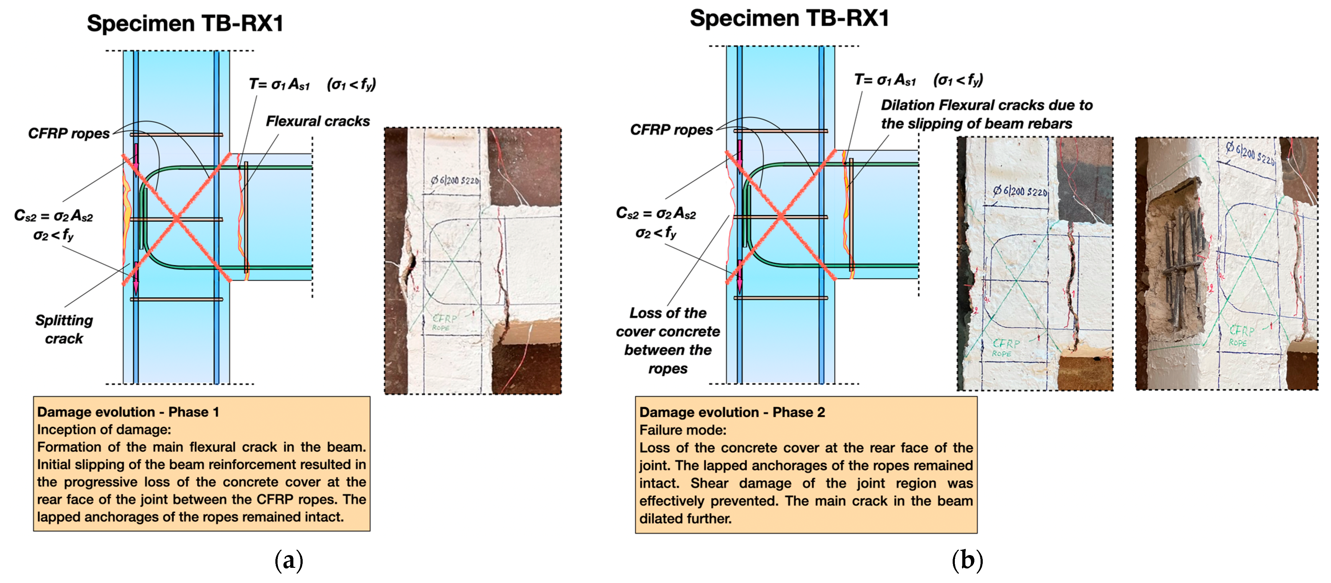
3.1.2. Strengthened Subassemblage TB-RX1

The beam–column joint specimen TB-RX1 was similar to the original subassemblage 4TB-A-3 and was strengthened by one wrapping of CFRP ropes in both diagonal directions of the joint region before the imposition of the seismic loading. Thereafter, it was subjected to the same history of reversed lateral displacements as the original specimen 4TB-A-3. The damage initiated in the beam with the formation of the main flexural cracks in the vicinity of the joint during the first cycle of loading (upper a-half-cycle 1a and lower a-half-cycle 1a) (see Figure 6a). These cracks propagated during the subsequent cycles and formed a single crack. The latter gradually dilated (slightly) due to the slipping of the beam longitudinal reinforcing bars. Meanwhile, a hairline splitting crack was formed for drift angle R = 1.90% at the back side of the joint, since the vertical segment of the beam rebars’ anchorage was slightly pushed out of the joint because of the bar slipping, being obstructed by the joint tie (see Figure 6b). During the first upper half-cycle for drift angle R = 2.86% (upper a-half-cycle 4a) further propagation of this crack along the joint height was observed. Thereafter, the progressive dilation of the splitting crack resulted in the loss of the concrete cover at the rear face of the joint region between the locations of the CFRP ropes’ anchorages for drift angle R = 4.29% (lower b-half-cycle 7b) (see Figure 6b). It is noteworthy that the axial bearing capacity of the specimen was not influenced at all, while the lateral strength increased during the subsequent cycles of loading (see Figure 8c and Figure 10). Most importantly, the joint core of TB-RX1 remained intact until the end of testing (for drift angle R = 5.71%), while no shear cracking was observed.
Due to the failure mode of the strengthened subassemblage TB-RX1, the specimen maintained its lateral load capacity to a large extent. In particular, for drift angle R = 1.90% (upper a-half-cycle 2a and lower a-half-cycle 2a), the strength was reduced by 7.67% and 15.35% with respect to its initial value for R = 1.43% during upper a-half-cycle 1a and lower a-half-cycle 1a, respectively. For load-point displacement of 30 mm (upper a-half-cycle 4a) when hairline splitting cracks were formed at the back side of the joint, specimen TB-RX1 retained 84.55% of its initial strength during the upper a-half-cycle 1a. After loss of the concrete cover between the anchorages of the CFRP ropes, an increase in strength by 18.69% was observed for R = 4.76% (lower a-half-cycle 8a), while at the end of the seismic test (for drift angle R = 5.71%), specimen TB-RX1 maintained 76.87% and 61.61% of its initial strength during the upper a-half-cycle 1a and the lower a-half-cycle 1a, respectively (see Figure 8c and Figure 10a). During the second cycles (b-cycles) and the third cycles (c-cycles) for each displacement step of the displacement-controlled history, the maximum lateral strength (for drift angle R = 1.43%) for the upper and lower half-cycles equaled 88.48%/69.29% and 80.71%/65.36%, respectively, of the corresponding values for the first cycles (a-cycles). The reduction in lateral strength values of TB-RX1 during the second half-cycles (b-half-cycles) and the third half-cycles (c-half-cycles) was mild, while a sharper decrease was observed for drift angle values R between 2.86% and 3.81% during the upper c-half-cycles (see Figure 10b,c).
The initial value of the peak-to-peak stiffness of TB-RX1 for drift angle R = 1.43% equaled that of specimen 4TB-A and was slightly higher than the value of 4TB-A-3 (see Figure 12a). For drift angle R = 1.90%, a reduction in the stiffness of TB-RX1 by 33.70% was observed with respect to the initial value for R = 1.43%. Subsequently, the stiffness reduction rate decreased, and the specimen at the end of the seismic test (R = 5.71%) maintained 17.81% of its initial stiffness (for R = 1.43%).
The strengthened subassemblage TB-RX1 exhibited a more stable and dissipating hysteresis performance with respect to the original specimen 4TB-A-3 (and to 4TB-A). This is clearly demonstrated in the hysteresis loops (see Figure 8c), the plots of energy dissipation capacity versus displacement illustrated in Figure 13a,b and the plots of cumulative energy dissipation per step of lateral displacement versus displacement depicted in Figure 14a. For drift angle R = 1.90% (a-cycle 2a), the dissipated seismic energy degraded by 39.71% with respect to its initial value for R = 1.43% (during the a-cycle 1a). Subsequently, the energy dissipation capacity continuously increased during the consecutive cycles of the earthquake-type loading until the end of testing (R = 5.71%). The same was also true for the second (b-cycles) and the third (c-cycles) cycles of loading. However, the decrease in values between b-cycle 2b and b-cycle 1b was particularly limited, equal to 14.16%, while the energy dissipation capacity increased during c-cycle 2c with respect to c-cycle 1c by 18.44%. For drift angle R = 5.71%, specimen TB-RX1 dissipated 94.67%, 194.86% and 312.94% of its corresponding initial energy capacity during a-cycle 1a, b-cycle 1b and c-cycle 1c, respectively. Therefore, the strengthened subassemblage TB-RX1 exhibited an overall dissipating hysteresis behavior with continuously increasing values, except the initial decrease observed during a-cycle 2a. The latter may be attributed to the initial slipping of the longitudinal reinforcing bars when the main flexural crack was formed. A notable increase in the cumulative energy dissipation capacity during consecutive cycles of loading can be observed in the plots illustrated in Figure 13b and Figure 14. Moreover, the increasing capacity rate in the case of TB-RX1 was significantly higher than that of the original specimen 4TB-A-3 (and of 4TB-A) (see Figure 13a,b and Figure 14b), while it continued until drift angle R = 5.71% (end of testing of TB-RX1), which is significantly higher than the values R = 4.76% (corresponding to failure of 4TB-A-3) and R = 4.29% (when 4TB-A collapsed). This is due to the satisfactory application of the CFRP ropes, which effectively allowed for the transferring of shear forces in the joint and ensured its elastic behavior.
Figure 6. Evolution of the seismic damage and failure mode of the strengthened beam–column joint subassemblage TB-RX1: (a) phase 1 and (b) phase 2—failure mode.
Buildings 15 02409 g006

3.1.3. Strengthened Subassemblage TB-RX2

The strengthening process of TB-RX2 included double wrapping of the CFRP ropes in both diagonal directions of the beam–column joint region, while the retrofitted specimen was subjected to the same displacement protocol as specimens 4TB-A-3 and TB-RX1, shown in Figure 3b. The main flexural crack was formed in the beam in the juncture with the joint during upper a-half-cycle 1a and lower a-half-cycle 1a (see Figure 7a). The resulting beam deformation triggered the initial slipping of the plain steel beam rebars due to local loss of bonding in the location of the main flexural crack. Subsequently, further slipping of reinforcement in the subsequent cycles for the same drift angle R = 1.43% (b-cycle 1b and c-cycle 1c) resulted in the slight extrusion of the anchorage of the beam rebars from the joint and the formation of a hairline splitting crack at the back side of the joint during c-cycle 1c (R = 1.43%) (see Figure 7b,c). Further evolution of damage was particularly limited and included only partial loss of the concrete cover between the anchorages of the CFRP ropes at the rear face of the joint, which did not occur before upper a-half-cycle 6a (R = 3.81%) (see Figure 7d). Total loss of the concrete cover of this particular location was observed during upper c-half-cycle 8c (R = 4.76%). Nevertheless, the lateral bearing capacity of TB-RX2 increased during the subsequent cycles until the end of testing for R = 6.19%. Furthermore, the specimen preserved its axial strength, while no shear damage of the joint was observed at all. Thus, the joint core of TB-RX2 remained intact, and the subassemblage exhibited an overall ductile hysteresis performance with concentration of damage mainly in the beam. The double wrapping of CFRP ropes at both diagonals of the beam–column joint was very satisfactory in preventing shear damage and even more effective with respect to the single wrapping (in the case of specimen TB-RX1) in increasing deformation capacity and energy dissipation.
The lateral strength of subassemblage TB-RX2 was more stable with respect to that of specimens TB-RX1, 4TB-A-3 and 4TB-A. An initial degradation of lateral capacity by 24.07% and 25% was observed during upper a-half-cycle 2a and lower a-half-cycle 2a (R = 1.90%) with respect to the values for R = 1.43% (upper a-half-cycle 1a and lower a-half-cycle 1a), respectively (see Figure 8d and Figure 10a). Thereafter, the lateral strength ranged from 55.17% to 68.98% (during the upper a-half-cycles) and from 75% to 78.51% (during the lower a-half-cycles) of its corresponding initial values during a-cycle 1a (R = 1.43%). At the end of the seismic test (for drift angle R = 6.19%), TB-RX2 maintained 55.17% and 78.51% of its initial lateral capacity during upper a-half-cycle 1a and lower a-half-cycle 1a, respectively. During the b-cycles and the c-cycles of the earthquake-type loading, the maximum lateral strength was also observed for drift angle R = 1.43% (during b-cycle 1b and c-cycle 1c). These strength values equaled 79.32%/53.51% and 72.46%/50% of the corresponding ones during upper a-half-cycle 1a and lower a-half-cycle 1a (see Figure 10b,c). The lateral strength of TB-RX2 remained almost stable during the b-cycles and the c-cycles of loading, especially during the lower half-cycles.
The peak-to-peak stiffness of subassemblage TB-RX2 was almost identical to that of the strengthened specimen TB-RX1 throughout testing, while the initial stiffness of TB-RX2 was slightly higher than that of TB-RX1 for drift angle R = 1.43%. A reduction in the stiffness of TB-RX2 by 43.21% was observed for R = 1.90%, while for R = 6.19%, the specimen retained 15.43% of its initial stiffness (see Figure 12a).
The strengthened subassemblage TB-RX2 showed an indisputable superiority in dissipating seismic energy with respect to all specimens—4TB-A, 4TB-A-3 and TB-RX1. This is clearly demonstrated in the plots of resisted shear force versus displacement, energy dissipation capacity versus displacement and cumulative energy dissipation per step of lateral displacement versus displacement, illustrated in Figure 8d, Figure 13c and Figure 14. A significant degradation by 54.61% in energy dissipation capacity was observed during a-cycle 2a (R = 1.90%) with respect to a-cycle 1a (R = 1.43%), due to the initial slipping of the beam reinforcement. However, during all the subsequent consecutive cycles of the displacement-controlled history (a-cycles, b-cycles and c-cycles), the energy dissipation capacity increased considerably and at a higher rate with respect to the strengthened specimen TB-RX1. During the b-cycles, the decrease in energy dissipation capacity for R = 1.90% (for b-cycle 2b) with respect to the value for R = 1.43% (for b-cycle 1b) was substantially lower (24.56%), while an increase in capacity was observed in the case of dissipated energy value for c-cycle 2c with respect to the corresponding value for c-cycle 1c. Subsequently, the ratio of cumulative energy dissipation capacity for each step of lateral displacement to the cumulative capacity for R = 1.43% ranged from 0.74 to 1.39 (see Figure 14b). It is worth noting that for drift angle R = 5.71% TB-RX2 dissipated 83.30%, 180.80% and 313.90% of its corresponding initial energy capacity during a-cycle 1a, b-cycle 1b and c-cycle 1c, respectively. At the end of testing (for drift angle R = 6.19%), the corresponding values equaled 94.94% (in the case of a-cycle 11a) and 216.96% (in the case of b-cycle 11b).
Figure 7. (ad) Evolution of the seismic damage of the strengthened beam–column joint subassemblage TB-RX2 and (e) failure mode.
Buildings 15 02409 g007
Figure 8. Plots of resisted shear force versus displacement of (a) the original specimen 4TB-A-3, (c) The strengthened specimen TB-RX1, (d) the strengthened specimen TB-RX2 and (b) envelope curve of specimen 4TB-A [24].
Buildings 15 02409 g008
Figure 9. Comparison of the hysteresis loops (a) of the strengthened specimen TB-RX1 with respect to the original specimen 4TB-A-3 and (b) of the strengthened specimen TB-RX2 with respect to the original specimen 4TB-A-3.
Buildings 15 02409 g009
Figure 10. Envelope curves of (a) the 1st cycles (a-cycles), (b) the 2nd cycles (b-cycles), and (c) the 3rd cycles (c-cycles) of subassemblages 4TB-A, 4TB-A-3, TB-RX1 and TB-RX2.
Buildings 15 02409 g010

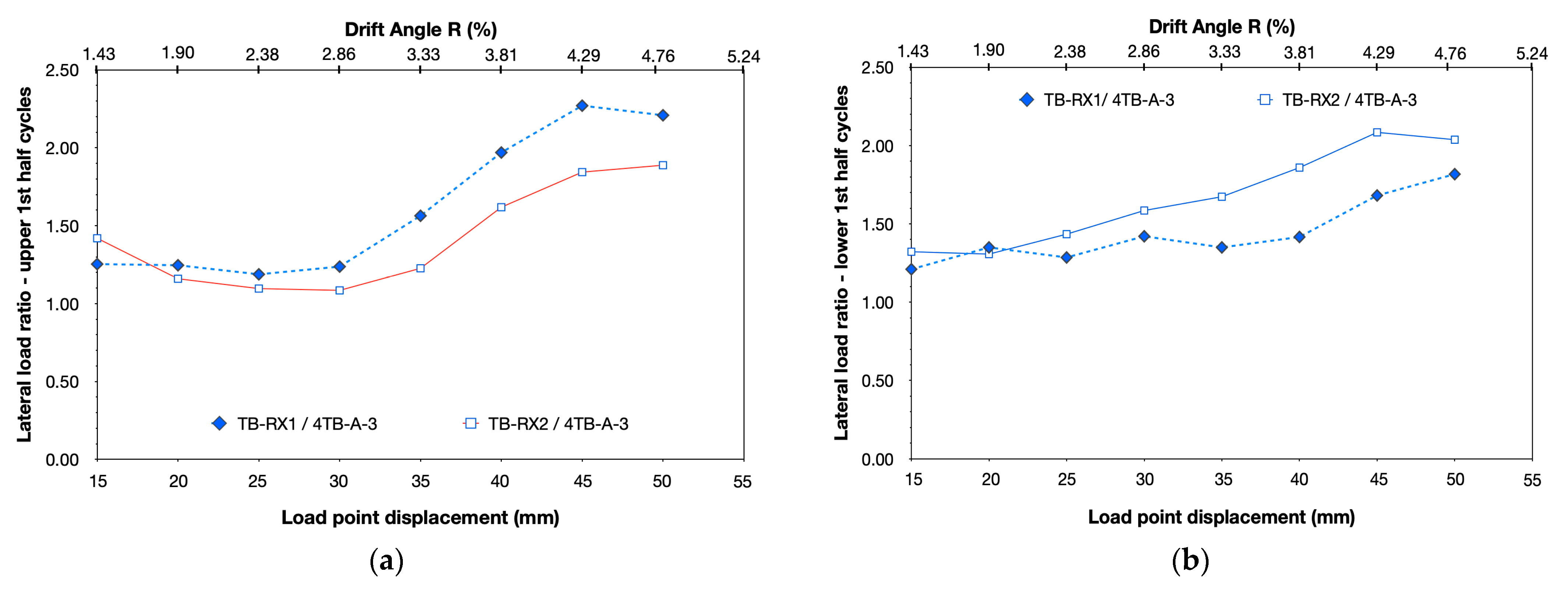
3.2. Comparison of the Seismic Performance of the Subassemblages

The comparative analysis of experimental data acquired during the seismic tests of the beam–column joint subassemblages is essential for understanding the influence of the structural inadequacies and the retrofit measures undertaken in the hysteresis response. Furthermore, it is crucial for evaluating the effectiveness and reliability of the proposed retrofit schemes. Thus, valuable information can be provided to practicing engineers, regarding how to design and satisfactorily apply the proposed retrofit scheme to allow for the exploitation of the advantages of CFRP ropes and, hence, achieve the effective transformation of the brittle seismic behavior to a ductile dissipating hysteresis performance.
In Table 2, the maximum lateral load values for each displacement step for the upper and lower a-half-cycles are summarized. In Figure 11a,b, the lateral load ratios versus load-point displacement TB-RX1/4TB-A-3 and TB-RX2/4TB-A-3 are shown for the upper and the lower a-half-cycles, respectively. The ratio values TB-RX1/4TB-A-3 ranged from 1.19 to 2.27 in the case of the upper a-half-cycles and from 1.21 to 1.82 in the case of the lower ones. The corresponding ratio values TB-RX2/4TB-A-3 ranged from 1.09 to 1.89 and from 1.31 to 2.08, respectively. These ranges are due to the progressive evolution of the joint shear damage of the original specimen 4TB-A-3, which, eventually, adversely affected its lateral bearing capacity. Meanwhile, the satisfactory (tight) application of the CFRP ropes in the diagonal directions of the joint region of subassemblages TB-RX1 and TB-RX2 prevented the extensive damaging of the beam–column connection and allowed for the elastic response of the joint concrete core. It is worth noting that the significant increase observed in lateral load ratios TB-RX1/4TB-A-3 and TB-RX2/4TB-A-3, especially for drift angle values R greater than 2.86%, was achieved without using additional longitudinal steel reinforcement, but solely by preserving and exploiting the inherent strength of the subassemblages, which, due to the retrofitting, performed in a more ductile manner showing concentration of damage mainly in the beam. Conversely, the brittle hysteresis behavior of the original specimen, 4TB-A-3, caused the exacerbation of its lateral strength.
The implementation of the proposed retrofit scheme in specimens TB-RX1 and TB-RX2 did not influence the cross-sectional dimensions of the subassemblages. Moreover, no additional steel longitudinal reinforcement was used. As a result, potential differences in the peak-to-peak stiffness values of the strengthened specimens with respect to the stiffness of the original subassemblage 4TB-A-3 are expected to be minor. After all, the proposed retrofit scheme mainly aims to enhance deformability, to improve the energy dissipation capacity and, hence, to ensure increased ductility without increasing stiffness. The peak-to-peak stiffness ratio TB-RX1/TB-RX2 during the a-cycles of the earthquake-type loading ranged from 0.95 to 1.11, showing that both strengthened specimens had similar stiffness throughout testing. The ratio values TB-RX1/4TB-A-3 and TB-RX2/4TB-A-3 ranged from 1.23 to 1.99 and from 1.23 to 1.97, respectively (see Figure 12b). A significant increase in the stiffness ratio values of TB-RX1/4TB-A-3 and TB-RX2/4TB-A-3 occurred for drift angles greater than 2.81% (R > 2.81%). The latter is due to the formation of splitting cracks at the back side of the joint of 4TB-A-3 for R = 2.86% and, primarily, to the subsequent evolution of the joint shear cracking, which dominated the failure mode of the original specimen 4TB-A-3, particularly for drift angles beyond R > 3.33%.
Figure 11. Lateral load ratios TB-RX1/4TB-A-3 and TB-RX2/4TB-A-3 for (a) the 1st upper half-cycles (upper a-half-cycles) and (b) the 1st lower half-cycles (lower a-half-cycles).
Buildings 15 02409 g011
Figure 12. (a) Plots of peak-to-peak stiffness versus displacement of specimens 4TB-A, 4TB-A-3, TB-RX1 and TB-RX2 and (b) plots of peak-to-peak stiffness ratios versus displacement of TB-RX2/TB-RX1, TB-RX1/4TB-A-3 and TB-RX2/4TB-A-3.
Buildings 15 02409 g012
Figure 13. Plots of energy dissipation capacity versus displacement for the a-cycles, b-cycles and c-cycles for each displacement step and total energy dissipation capacity for each displacement step: (a) original subassemblage 4TB-A-3, (b) strengthened subassemblage TB-RX1 and (c) strengthened subassemblage TB-RX2.
Buildings 15 02409 g013
Figure 14. (a) Plots of cumulative energy dissipation per step of lateral displacement versus displacement for specimens 4TB-A-3, 4TB-A, TB-RX1 and TB-RX2 and (b) plots of cumulative energy dissipated during each displacement step with respect to that dissipated during the first displacement step versus displacement for specimens 4TB-A-3, 4TB-A, TB-RX1 and TB-RX2.
Buildings 15 02409 g014
The extent, level and nature of damage is closely related to the energy dissipation capacity [24]. Thus, continuously increasing values of energy dissipation capacity during consecutive cycles of the earthquake-type loading suggest a ductile hysteresis behavior. Conversely, the stable or decreasing energy dissipation reflects a failure mode of brittle nature that causes degrading seismic performance. Hence, from the plots of energy dissipation capacity versus displacement of the original specimen 4TB-A-3 (see Figure 8a) and the plots of cumulative energy dissipated during each displacement step to the cumulative energy dissipated during the first step versus displacement (see Figure 14b), it is evident that the structural member exhibited poor hysteresis behavior dominated by brittle failure mechanisms including both slipping of the beam reinforcement and shear cracking of the beam–column joint region. This can also be perceived in the plots of resisting shear force versus displacement of 4TB-A-3 depicted in Figure 8a and Figure 9a,b. The hysteresis loops of 4TB-A-3 are narrow with significant pinching around the axes and stable or even decreasing area for increasing values of lateral displacement (in all cases of a-cycles, b-cycles and c-cycles). For instance, during the last cycle of the earthquake-type loading (R = 4.76%), the cumulative dissipated energy of the original specimen 4TB-A-3 equaled only 89.61% of the initial cumulative dissipated energy value for drift angle R = 1.43%. The ratio of cumulative dissipated energy for each displacement step to that dissipated during the first displacement step ranged from 1.0 to 0.74 (see Figure 14b). The corresponding ratio values for the strengthened subassemblages TB-RX1 and TB-RX2 ranged from 0.76 to 1.55 and from 0.61 to 1.40, respectively. Furthermore, at the end of testing, the cumulative dissipated energy equaled 155% (in the case of TB-RX1 for R = 5.71%) and 140% (in the case of TB-RX2 for R = 6.19%) of their corresponding initial value for drift angle R = 1.43%. Meanwhile, for drift angle R = 4.76% (at the end of testing of 4TB-A-3), the cumulative dissipated energy capacity of the strengthened specimens TB-RX1 and TB-RX2 was increased with respect to the corresponding value for the original specimen 4TB-A-3 by 60.92% and 78.23%, respectively. Apparently, the applied retrofit scheme successfully improved the ductility of the strengthened beam–column joint subassemblages with respect to the original specimen by eliminating the devastating influence of shear damage in the joint region.
It should also be noted that, regarding energy dissipation, the original specimen 4TB-A-3 showed increased capacity values with respect to specimen 4TB-A [24] (see Figure 14a and Figure 15). This is due to the different displacement-controlled protocol according to which the two subassemblages were tested, as well as to the differences in evolution of damage of the specimens described in Section 3.1.1.
The inelastic characteristics of the structural member and its deformation capacity during strong seismic excitations are directly related to the energy dissipation capacity and, hence, depend on the displacement ductility. Therefore, the equivalent viscous damping coefficient, ζ e q , which consists of both the hysteretic and the elastic damping, can be used to evaluate the seismic performance of the beam–column joint subassemblages. In Figure 15, the plots of equivalent viscous damping coefficient for the a-cycles versus displacement versus the energy dissipation capacity for the a-cycles are illustrated. The higher the values of the equivalent viscous damping coefficient are, the more ductile dissipating hysteresis is exhibited by the subassemblages, while degrading energy dissipation capacity reflects severe damage and/or potential collapse under small deformations due to the cumulative seismic energy [24]. The coefficient ζ e q is the ratio of the energy dissipated within a given cycle of loading to the elastic strain energy which corresponds to this cycle (see Figure 15). The values of ζ e q were higher for the retrofitted specimens with respect to the original one, 4-TB-A-3 (particularly in the case of TB-RX2), due to the increased area of the hysteresis loops. The increase in value of ζ e q for drift angle R = 3.81% in the case of specimen 4TB-A is due to the substantial reduction in its shear resistance, which resulted in notably lower elastic strain energy during the last cycle [24].
Figure 15. Plots of energy dissipation during the 1st cycles versus displacement versus equivalent viscous damping coefficient for subassemblages 4TB-A, 4TB-A-3, TB-RX1 and TB-RX2.
Buildings 15 02409 g015

4. Conclusions

The effectiveness and reliability of a proposed strengthening scheme used to improve the hysteresis behavior of substandard RC beam–column joints were experimentally investigated. One specimen, 4TB-A-3, was tested as-built and used as the control specimen, while the other two specimens, TB-RX1 and TB-RX2, were retrofitted prior to seismic loading. The CFRP ropes were used as near-surface-mounted (NSM) shear reinforcement, while they were applied under tension by hanging weights to ensure their tight application and prevent shear cracking of the joint concrete core. To study the influence on seismic behavior of damage accumulation during multiple cycles of loading, as well as the influence of improved anchorage conditions when using transversely welded rebars to the beam reinforcement, one more specimen was used, 4TB-A. This specimen was tested in previous research [24]. Based on the experimental results, the following conclusions were drawn:
  • The seismic behavior of the original beam–column joint subassemblage 4TB-A-3 was dominated by brittle failure modes including slipping of the beam longitudinal reinforcement and shear cracking of the joint region. As a result, the specimen exhibited poor hysteresis performance with limited energy dissipation capacity, degrading lateral strength and low ductility.
  • The excessive shear damage of 4TB-A resulted from the significantly increased forces in the joint region due to the improved anchorage conditions of the beam rebars, achieved by using transversely welded bar segments [24]. These were not provided in the case of subassemblage 4TB-A-3. Hence, slipping of the beam rebars from the joint region of 4TB-A-3 initially occurred, and consequently, shear cracking of the joint was delayed with respect to specimen 4TB-A. Therefore, despite being subjected to multiple (three) cycles of the earthquake-type loading per displacement step (with respect to the similar specimen 4TB-A), the original specimen 4TB-A-3 did not collapse for drift angle R = 4.29% (when specimen 4TB-A collapsed) and retained its axial load carrying capacity for R = 4.76%. Nevertheless, the failure mode of both subassemblages was eventually dominated by shear failure of the beam–column connection.
  • The proposed retrofit scheme proved to be very satisfactory in preventing shear damage of the joint region and in shifting the damage mainly in the beam of the strengthened subassemblages, TB-RX1 and TB-RX2. Therefore, the structural integrity of the retrofitted specimens was effectively preserved, while deformation capacity and ductility were significantly improved.
  • Partial loss of the concrete cover at the rear face of the exterior beam–column joint specimens TB-RX1 and TB-RX2 occurred due to the initial slipping of the beam reinforcement and the consequential slight push-out of the hook of the bar anchorage from the joint (since only one Ø6mm tie was provided). This loss, however, had no adverse influence at all in axial load-carrying capacity and in lateral strength of the subassemblages, while it was limited solely in the height between the CFRP ropes.
  • After loss of the concrete cover, the lateral bearing capacity of TB-RX1 and TB-RX2 increased during the consecutive cycles of the earthquake-type loading, demonstrating that the joint concrete core remained elastic, and shear cracking was effectively prevented.
  • The original specimen 4TB-A collapsed due to the loss of axial load-carrying capacity for drift angle R = 4.29%. Also, the original subassemblage 4TB-A-3 retained only 35.55% and 40.15% of its initial strength values during the upper and lower half-cycles for R = 4.71%, respectively. Conversely, the strengthened subassemblages, TB-RX1 and TB-RX2, exhibited a more stable hysteresis performance and maintained 80.70% (for R = 5.71%) and 60.02% (for R = 6.19%) of their initial strength, respectively.
  • The significant increase in lateral load ratio values TB-RX1/4TB-A-3 (up to 2.27) and TB-RX2/4TB-A-3 (up to 1.82), especially for drift angle values R greater than 2.86%, was achieved without using additional longitudinal steel reinforcement, but solely by preserving and exploiting the inherent strength of the subassemblages which, due to the retrofitting, performed in a more ductile manner.
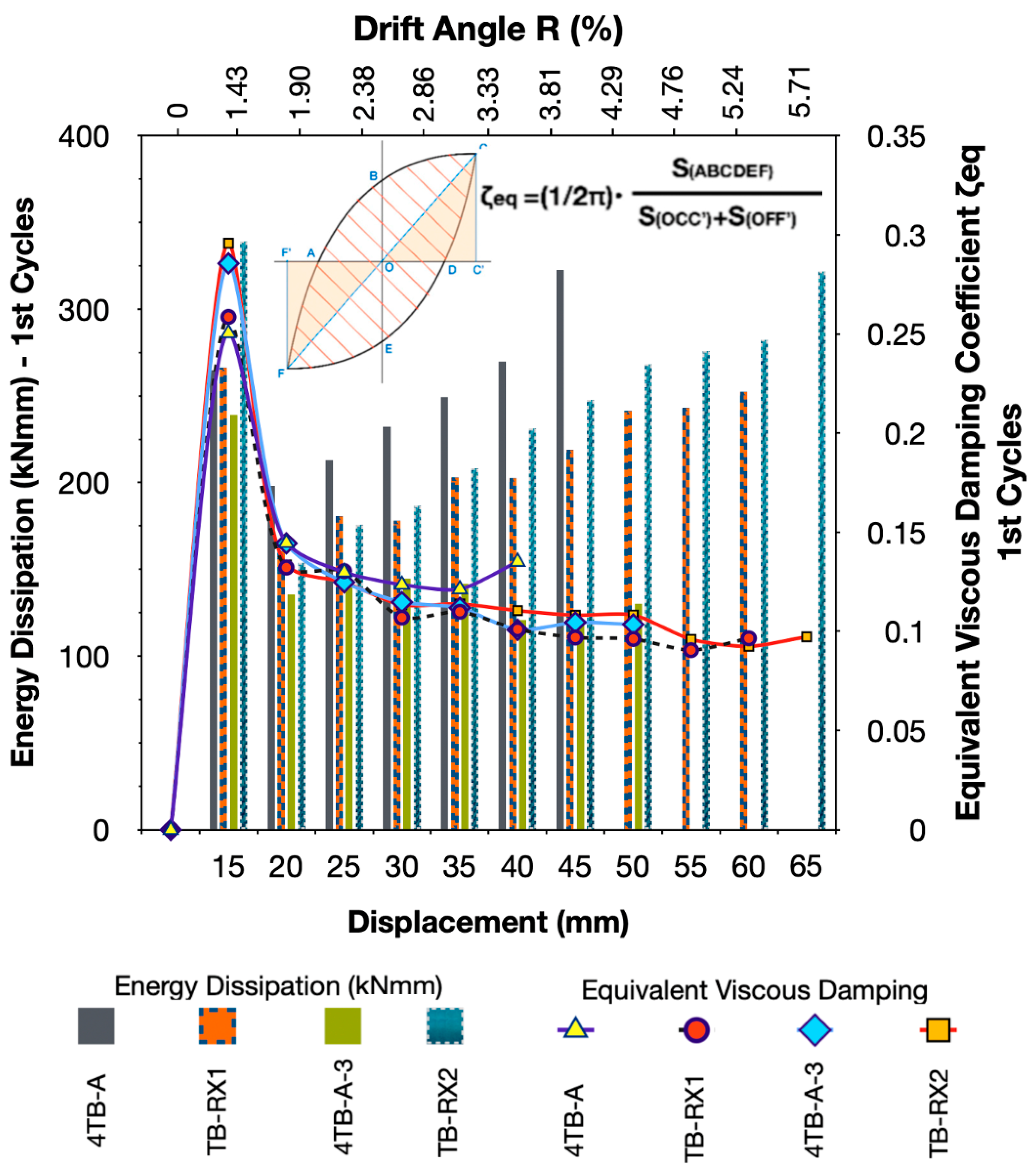
  • The strengthened subassemblages were subjected to a significant number of inelastic cycles of incremental lateral displacements, showing substantially improved energy dissipation capacity with respect to the original specimens, 4TB-A and 4TB-A-3. For drift angle R = 4.76% (end of testing of 4TB-A-3), the cumulative dissipated energy capacity of the strengthened specimens TB-RX1 and TB-RX2 was increased with respect to the corresponding value for the original specimen 4TB-A-3 by 60.92% and 78.23%, respectively. Furthermore, the joint concrete core of both TB-RX1 and TB-RX2 remained intact until the end of the seismic tests. Ultimately, the proposed retrofit scheme successfully transformed the failure mode of the subassemblages, which was dominated by brittle shear in the case of 4TB-A and 4TB-A-3, to a ductile one with concentration of damage mainly in the beam.
  • The proposed retrofit scheme provides additional essential advantages regarding the ease of application, cost-effectiveness, limited labor demands, low disturbance and, primarily, the ability to be used even in the case of interior beam–column joints linking beams in all directions. Thus, it seems particularly competitive and convenient with respect to other strengthening schemes, especially when the primary goal is the improvement of ductility and energy dissipation capacity of the existing substandard RC structures. Given that the proposed retrofit scheme does not change the inertial characteristics of the structure, its application would possibly be more efficient when combined with the addition of RC walls which make the structure more rigid. Also, alternative placement of the CFRP ropes (not in the diagonal directions of the joint region) may also be used to avoid even minor damage and ensure that the joint remains totally intact.

Author Contributions

Conceptualization, C.K. and G.K.; methodology, G.K.; software, G.K.; validation, C.K., G.K. and A.K.; formal analysis, G.K.; investigation, G.K., A.K., G.N. and E.-T.G.; resources, G.K.; data curation, G.K., G.N. and E.-T.G.; writing—original draft preparation, G.K.; writing—review and editing, C.K. and G.K.; visualization, G.K.; supervision, G.K. All authors have read and agreed to the published version of the manuscript.

Funding

This research was funded by the Special Account for Research Funds of the Aristotle University of Thessaloniki.

Data Availability Statement

The original contributions presented in the study are included in the article, further inquiries can be directed to the corresponding author.

Acknowledgments

The authors gratefully acknowledge the kind donation of the steel reinforcement by Sidenor S.A. industry. Moreover, the authors would like to express their thanks to the civil engineer Chrysovalantis—Tsampikos Charteros for his contribution during the stage of acquiring measurements during the micro-tensile testing of the CFRP ropes.

Conflicts of Interest

The authors declare no conflicts of interest.

References

  1. De Risi, M.T.; Del Vecchio, C.; Ricci, P.; Ludovico, M.D.; Prota, A.; Verderame, G.M. Light FRP Strengthening of poorly detailed reinforced concrete exterior beam-column joints. J. Compos. Constr. 2020, 24, 04020014. [Google Scholar]
  2. Karayannis, C.G.; Sirkelis, G.M. Strengthening and rehabilitation of RC beam-column joints using FRP jacketing and epoxy resin injections. J. Earthq. Eng. Struct. Dyn. 2008, 37, 769–790. [Google Scholar]
  3. Tsonos, A.G. Effectiveness of CFRP jackets in post-earthquake and pre-earthquake retrofitting of beam-column subassemblages. Struct. Eng. Mech. 2007, 27, 393–408. [Google Scholar]
  4. Tsonos, A.-D. Ultra-high-performance fiber reinforced concrete: An innovative solution for strengthening old R/C structures and for improving the FRP strengthening method. WIT Trans. Eng. Sci. 2008, 64, 273–284. [Google Scholar]
  5. Tsonos, A.-D. Effectiveness of CFRP-jackets and RC-jackets in post-earthquake and pre-earthquake retrofitting of beam-column subassemblages. Eng. Struct. 2008, 30, 777–793. [Google Scholar]
  6. Karayannis, C.G.; Golias, E. Full-scale tests of RC joints with minor to moderate damage repaired using C-FRP sheets. Earthq. Struct. 2018, 15, 617–627. [Google Scholar]
  7. Pohoryles, D.A.; Melo, J.; Rossetto, T.; Varum, H.; Bisby, L. Seismic retrofit schemes with FRP for deficient RC beam-column joints: State-of-the-art review. J. Compos. Constr. 2019, 23, 4. [Google Scholar]
  8. Murad, Y.; Al Bodur, W.; Ashteyat, A. Seismic retrofitting of severely damaged RC connections made with recycled concrete using CFRP sheets. Front. Struct. Civ. Eng. 2020, 14, 554–568. [Google Scholar]
  9. Tafsirojjaman, T.; Fawzia, S.; Thambiratnam, D.P. Structural behaviour of CFRP strengthened beam-column connections under monotonic and cyclic loading. Structures 2021, 33, 2689–2699. [Google Scholar]
  10. Mostofinejad, D.; Akhlaghi, A. Experimental Investigation of the Efficacy of EBROG Method in Seismic Rehabilitation of Deficient Reinforced Concrete Beam–Column Joints Using CFRP Sheets. J. Compos. Constr. 2017, 21, 04016116. [Google Scholar]
  11. Mostofinejad, D.; Akhlaghi, A. Flexural strengthening of reinforced concrete beam column joints using innovative anchorage system. ACI Struct. J. 2017, 114, 1603–1614. [Google Scholar]
  12. Dalfre, G.M.; Barros, J.A.O. NSM technique to increase the load carrying capacity of continuous RC slabs. Eng. Struct. 2013, 56, 137–153. [Google Scholar]
  13. Al-Mahmoud, F.; Castel, A.; François, R.; Tourneur, C. Strengthening of RC members with near-surface mounted CFRP rods. Compos. Struct. 2009, 91, 138–147. [Google Scholar]
  14. Alwash, D.; Kalfat, R.; Al-Mahaidi, R.; Du, H. Shear strengthening of RC beams using NSM CFRP bonded using cement based adhesive. Constr. Build. Mater. 2021, 301, 124365. [Google Scholar]
  15. Al-Saadi, N.T.K.; Mohammed, A.; Al-Mahaidi, R.; Sanjayan, J. A state-of-the-art review: Near-surface mounted FRP composites for reinforced concrete structures. Constr. Build. Mater. 2019, 209, 748–769. [Google Scholar]
  16. Ercan, E.; Arisoy, B.; Ertem, O.-B. Experimental Assessment of RC Beam-Column Connections with Internal and External Strengthening Techniques. Adv. Civ. Eng. 2019, 2828353. [Google Scholar] [CrossRef]
  17. Golias, E.; Zapris, A.G.; Kytinou, V.K.; Kalogeropoulos, G.I.; Chalioris, C.E.; Karayannis, C.G. Effectiveness of the novel rehabilitation method of seismically damaged rc joints using c-frp ropes and comparison with widely applied method using c-frp sheets—Experimental investigation. Sustainability 2021, 13, 6454. [Google Scholar]
  18. Chalioris, C.; Kosmidou, P.-M.; Papadopoulos, N. Investigation of a new strengthening technique for RC deep beams using carbon FRP ropes as transverse reinforcement. Fibers 2018, 6, 52. [Google Scholar] [CrossRef]
  19. Golias, E.; Vougioukas, E.; Wittemann, K.; Kalogeropoulos, G.; Karayannis, C. Cyclic response of RC beam-column joints setrngthened with transverse steel bars and with CFRP diagonal ties. Acta Polytech. 2022, 62, 274–282. [Google Scholar]
  20. Karayannis, C.; Golias, E. Full-scale experimental testing of RC beam-column joints strengthened using CFRP ropes as external reinforcement. Eng. Struct. 2022, 250, 113305. [Google Scholar]
  21. Karayannis, C.; Golias, E. Strengthening of deficient RC joints with diagonally placed C-FRP ropes. Earthq. Struct. 2021, 20, 123–132. [Google Scholar]
  22. Karayannis, C.; Golias, E.; Kalogeropoulos, G. Influence of Carbon Fiber-Reinforced Ropes Applied as External Diagonal Reinforcement on the Shear Deformation of RC Joints. Fibers 2022, 10, 28. [Google Scholar] [CrossRef]
  23. Kytinou, V.; Gribniak, V.; Golias, E.; Zapris, A.; Sapidis, G.; Chalioris, C. A novel technique for strengthening reinforced concrete shear-deficient members using fiber-reinforced polymer rope as near Surface Mounted reinforcement. In Olympiad in Engineering Science; Springer Nature: Cham, Switzerland, 2023; pp. 315–326. [Google Scholar]
  24. Kalogeropoulos, G.; Tsonos, A.-D.; Iakovidis, P. Hysteresis Behavior of RC Beam–Column Joints of Existing Substandard RC Structures Subjected to Seismic Loading–Experimental and Analytical Investigation. Buildings 2024, 14, 1609. [Google Scholar] [CrossRef]
  25. Herrmann, D. Methods for Determining the Modulus of Elasticity of Wire and Fibre Ropes. innoTRAC 2020, 1, 47–54. [Google Scholar] [CrossRef]
  26. Sika. Available online: https://grc.sika.com/dam/dms/gr01/r/sikawrap-fx-50-c.pdf (accessed on 6 July 2025).
  27. Hakuto, S.; Park, R.; Tanaka, H. Seismic load tests on interior and exterior beam-column joints with substandard reinforcing details. ACI Struct. J. 2000, 97, 11–25. [Google Scholar]
  28. Ehsani, M.R.; Wight, J.K. Effect of transverse and slab on behavior of reinforced concrete beam-to-column connections. ACI J. Proc. 1985, 82, 188–195. [Google Scholar]
  29. Durrani, A.J.; Wight, J.K. Earthquake resistance of reinforced concrete interior connections including a floor slab. ACI J. Proc. 1987, 84, 400–406. [Google Scholar]
  30. Soroushian, P.; Sim, J. Axial behavior of reinforced concrete columns under dynamic loads. ACI J. Proc. 1986, 83, 1018–1025. [Google Scholar]
  31. Scott, B.D.; Park, R.; Priestley, M.J.N. Stress-strain behavior of concrete confined by overlapping hoops at low and high strain rates. ACI J. Proc. 1982, 79, 13–27. [Google Scholar]
  32. CEB. CEB—FIP Modes Code 1990, Bulletin d’ Information CEB; CEB: Lausanne, Switzerland, 1993; pp. 213–214. [Google Scholar]
  33. Ehsani, M.R.; Wight, J.K. Exterior reinforced concrete beam-to-column connections subjected to earthquake-type loading. ACI J. Proc. 1985, 82, 492–499. [Google Scholar]
Figure 4. (a) Reaction frame and instrumentation used for the seismic tests; (b) part of an RC structure which is simulated by the exterior beam–column joint subassemblages.
Buildings 15 02409 g004
Table 2. Maximum lateral load (kN) per displacement step (a-cycles).
Displacement Step (mm)±15±20±25±30±35±40±45±50±55±60±65
Maximum lateral load (kN) (upper/lower a-half-cycles)
Specimen4TB-A *+11.53
−10.91
+10.91
−10.91
+10.60
−10.29
+10.29
−9.66
+9.66
−9.03
+8.42
−7.48
+5.61
−4.36
4TB-A-3+8.72
−9.04
+8.10
−6.86
+7.79
−6.55
+7.48
−5.93
+5.92
−5.61
+4.49
−5.05
+3.71
−4.51
+3.62
−4.40
TB-RX1+10.94
−10.94
+10.09
−9.26
+9.25
−8.42
+9.25
−8.42
+9.25
−7.58
+8.83
−7.16
+8.41
−7.58
+7.99
−8.00
+7.99
−7.58
+8.41
−6.74
TB-RX2+12.38
−11.96
+9.40
−8.97
+8.54
−9.39
+8.11
−9.39
+7.26
−9.39
+7.26
−9.39
+6.83
−9.39
+6.83
−8.97
+7.26
−9.39
+6.83
−9.39
+6.83
−9.39
* Specimen 4TB-A was subjected to a displacement-controlled history including one cycle per displacement step [24].
Disclaimer/Publisher’s Note: The statements, opinions and data contained in all publications are solely those of the individual author(s) and contributor(s) and not of MDPI and/or the editor(s). MDPI and/or the editor(s) disclaim responsibility for any injury to people or property resulting from any ideas, methods, instructions or products referred to in the content.

