Article

Experimental Behavior of Steel-Concrete Composite Girders with UHPC-Grout Strip Shear Connection

1
Key Laboratory of Concrete and Prestressed Concrete Structures of Ministry of Education, Southeast University, Nanjing 211189, China
2
Key Laboratory of Large-Span Bridge Construction Technology of Ministry of Communications, CCCC Second Harbour Engineering Company Ltd., Wuhan 430040, China
*
Author to whom correspondence should be addressed.
Buildings 2021, 11(5), 182; https://doi.org/10.3390/buildings11050182
Submission received: 31 March 2021 / Revised: 19 April 2021 / Accepted: 21 April 2021 / Published: 24 April 2021

Abstract

:
This paper develops a new type of shear connection for steel-concrete composite bridges using Ultra-High Performance Concrete (UHPC) as the connection grout. The UHPC-grout strip shear connection is fabricated by preforming a roughened slot in the concrete deck slab, welding an embossed steel rib longitudinally to the upper flange of the steel girder, and casting the strip void between the slot and the steel rib with UHPC grout. The structural performance of the new connection was validated by two sets of experimental tests, including push-out testing of shear connectors and static and fatigue testing of composite beams. The results of push-out testing indicate that the UHPC-grout strip shear connection exhibits a significant improvement of ductility, ultimate capacity, and fatigue performance. The interface shear strength of the UHPC-grout strip connection is beyond 15 MPa, which is about three times that of the strip connection using traditional cementitious grouts. The ultimate capacity of the connection is dominated by the interface failure between the embossed steel and the UHPC grout. The results of composite-beam testing indicate that full composite action is developed between the precast decks and the steel beams, and the composite action remained intact after testing for two million load cycles. Finally, the trail design of a prototype bridge shows that this new connection has the potential to meet the requirements for horizontal shear.

1. Introduction

In recent years, a prefabricated steel–concrete composite bridge system has been used increasingly in new constructions. A typical system is the full-depth deck panel system shown in Figure 1. Shear stud clusters embedded in shear pockets are applied to create composite action between precast decks and steel girders. The shear pockets are filled with field-cast cementitious grouts to generate the composite action. This innovative solution allows shorter time for the construction, while extending the service life of bridge decks [1,2]. Significant advances have been made to study the composite action between steel girders and precast decks when large clusters of studs are utilized [3,4,5,6,7]. Meanwhile, there are some potential problems with the use of clustered studs such as the shear connection [3,8], which include deck uplift, nonuniform distribution of horizontal shear along the interface, and local bearing failure of concrete in the shear pockets. Potential solutions to these problems would be the use of innovative detailing and/or advanced materials.
One potential solution is the use of strip or distributed connections, rather than point connections. They offer the advantage of minimizing the risk of local failures. Among various types of strip connections, one promising detailing is the “connection by adhesion, interlocking and friction,” which is first presented and studied by EPFL in Switzerland [9]. This innovative connection (Figure 2a) consists of a precast deck fabricated with a roughened slot in the lower part and an embossed steel rib welded longitudinally to the upper flange of the steel girder. The channel void under the precast panel is injected with cement grout. As shown in Figure 2b, the horizontal shear resistance of the connection is controlled by two interfaces: the grout-concrete interface (interface 1), and the steel-grout interface (interface 2). Papastergiou and Lebet [10] conducted several improvements to this type of connection, including the absence of a bonding layer on the upper flange to improve the brittle behavior of the connection, the presence of circular holes in the steel rib to generate a “dowel effect” [11], and the use of high-performance mortar as the injection [12]. The connection by adhesion, interlocking, and friction offers an alternative solution for the accelerated construction of steel–concrete composite bridges. However, previous studies conducted by Thomann and Lebet [13] and Papastergiou [14] pointed out that this connection usually exhibits less ductile behavior in comparison with the shear studs.
Another potential solution would be the utilization of high-performance materials such as Ultra-High Performance Concrete (UHPC) to ensure improved performance in the shear connections. UHPC-class materials typically exhibit compressive strengths beyond 120 MPa and tensile strengths above 5 MPa [15]. UHPC has been successfully applied in composite connections between precast concrete slabs and steel girders [16,17,18,19]. Recently, Haber et al. [20] proposed two new deck-to-girder composite connections employing UHPC, referred to as the UHPC shear lug connection and the rebar dowel connection. Both connection details exhibited good ultimate capacity and excellent ductility.
The objective of this paper is to develop an enhanced strip connection using UHPC as the connection grout. UHPC has better durability and mechanical properties over traditional cementitious grouts. Compared with existing strip connections using cement grout, the UHPC-grout strip shear connection allows for a significant improvement of ductility, ultimate capacity, and durability.

2. Experimental Program

Three sets of experiments were conducted to study the structural performance and constructability of UHPC-grout strip shear connections: (1) push-out tests of shear connectors; (2) static tests of composite beams; and (3) fatigue tests of composite beams. The experimental work is described in the following sections.

2.1. UHPC-Class Grout

The UHPC-class grout applied in this study is a commercially available product in China, which is composed of Portland cement, fine sand, silica fume, high active admixture, superplasticizer, steel fibers, and water. Table 1 shows the composition of this material. With regard to the steel fibers, the volumetric percentage is 1.5%, and the nominal length and diameter are13 mm and 0.2 mm, respectively. The average compressive strength of this UHPC-class grout is 125.6 MPa after 28 days of curing. Specimens were cured at ambient laboratory temperatures (25 °C ± 2 °C). The compressive strength is obtained from uniaxial compression tests on 150 × 150 × 150 mm cubic specimens. More details about the mix and properties of this UHPC-grout material are available in the report by He et al. [21].

2.2. Push-Out Testing of Shear Connectors

Three identical push-out test specimens were fabricated, as shown in Figure 3. Each specimen is assembled by two precast concrete blocks and a steel connector. The void in the connection is filled with UHPC-class grout. The concrete blocks are made of C50 concrete. The steel connector consists of a steel plate in which two embossed steel plates are welded. The surface of the inner rib of the concrete block was roughened by sand-blasting with at least 3 mm roughness at about 40 mm spacing. The embossed steel plate was roughed by 45° oriented grooves. These grooves are 2 mm deep and 10 mm wide. Circular holes (d = 50 mm) spaced at 150 mm were drilled in the embossed steel plate to generate a “dowel effect” that improves the shear strength of the connector. The above roughness treatments are the same as the specimens tested by Diógenes et al. [11].

2.3. Static and Fatigue Testing of Composite Beams

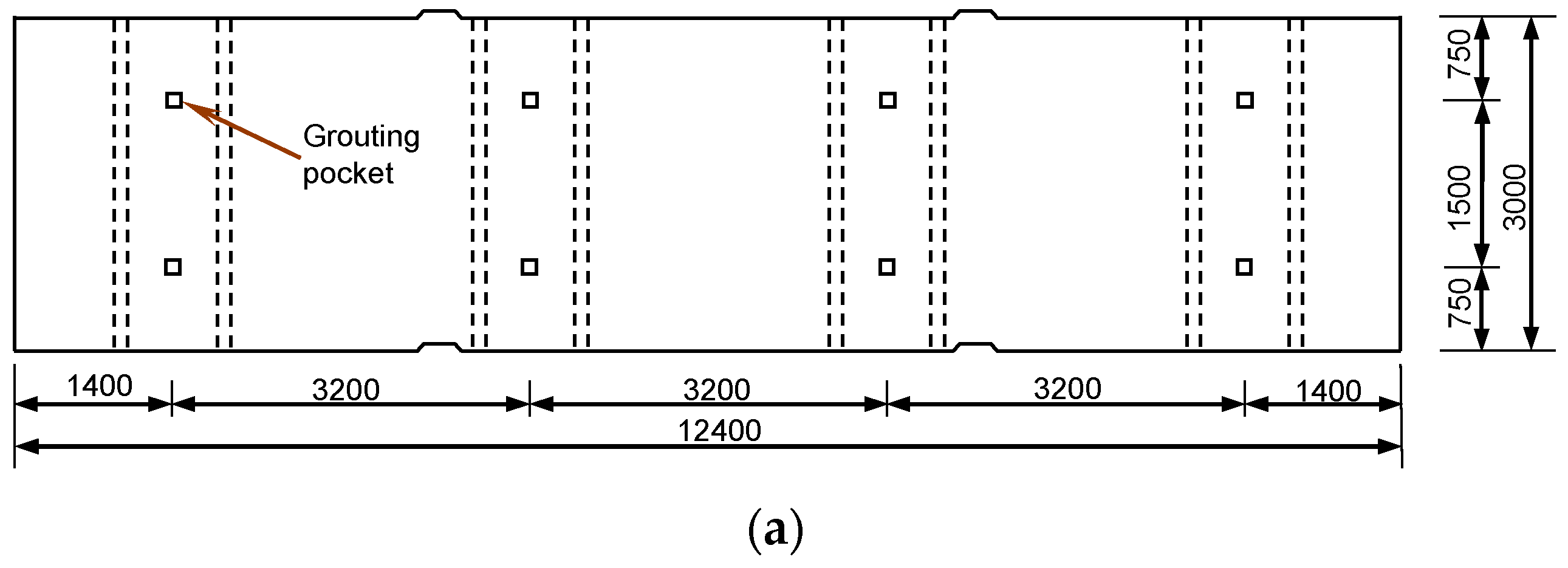
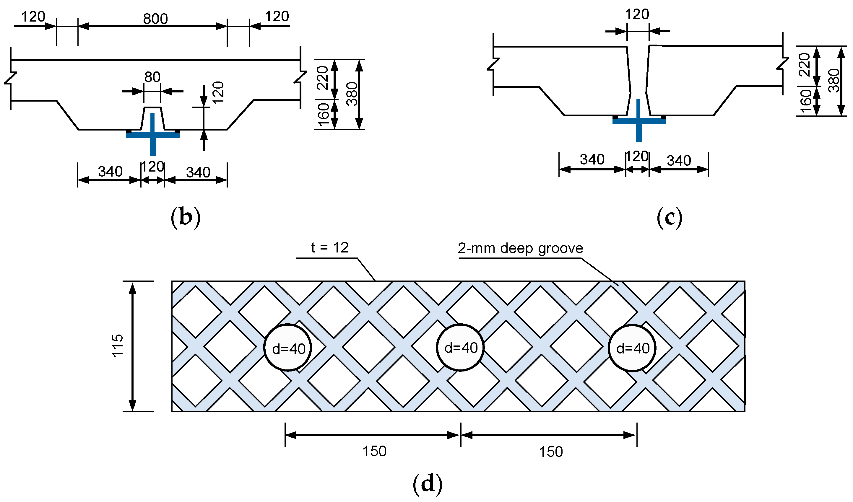
2.3.1. Specimen Design

Three identical specimens were fabricated to investigate the static and fatigue behavior of composite girders with UHPC-grout strip shear connections. Beam 1 and Beam 2 were loaded statically to failure, and Beam 3 was exposed to two million cycles of fatigue loads.
Figure 4 shows the general details of the composite beam specimens. Each specimen has a length of 4000 mm and a height of 400 mm. The precast deck slab is 4 m long × 0.5 m wide × 0.15 m thick. The steel girder is welded by three 12-mm-thick plates of Grade Q235 steel. The size of the longitudinal grouting channel in the concrete slab is 90 mm × 120 mm, and the grouting pockets have a size of 100 × 100 mm and a spacing of 1000 mm. The roughness treatments to the embossed steel plates and the grouting channel are the same as the push-out tests. The material properties of the concrete slab and the UHPC-grout are also the same as the push-out tests, as listed in Table 2.
Figure 5 shows the fabrication process of the composite beam specimens. After the precast concrete slab was installed on the steel girder, the interface between them was filled with the UHPC-grout through the pockets preformed in the precast slab.

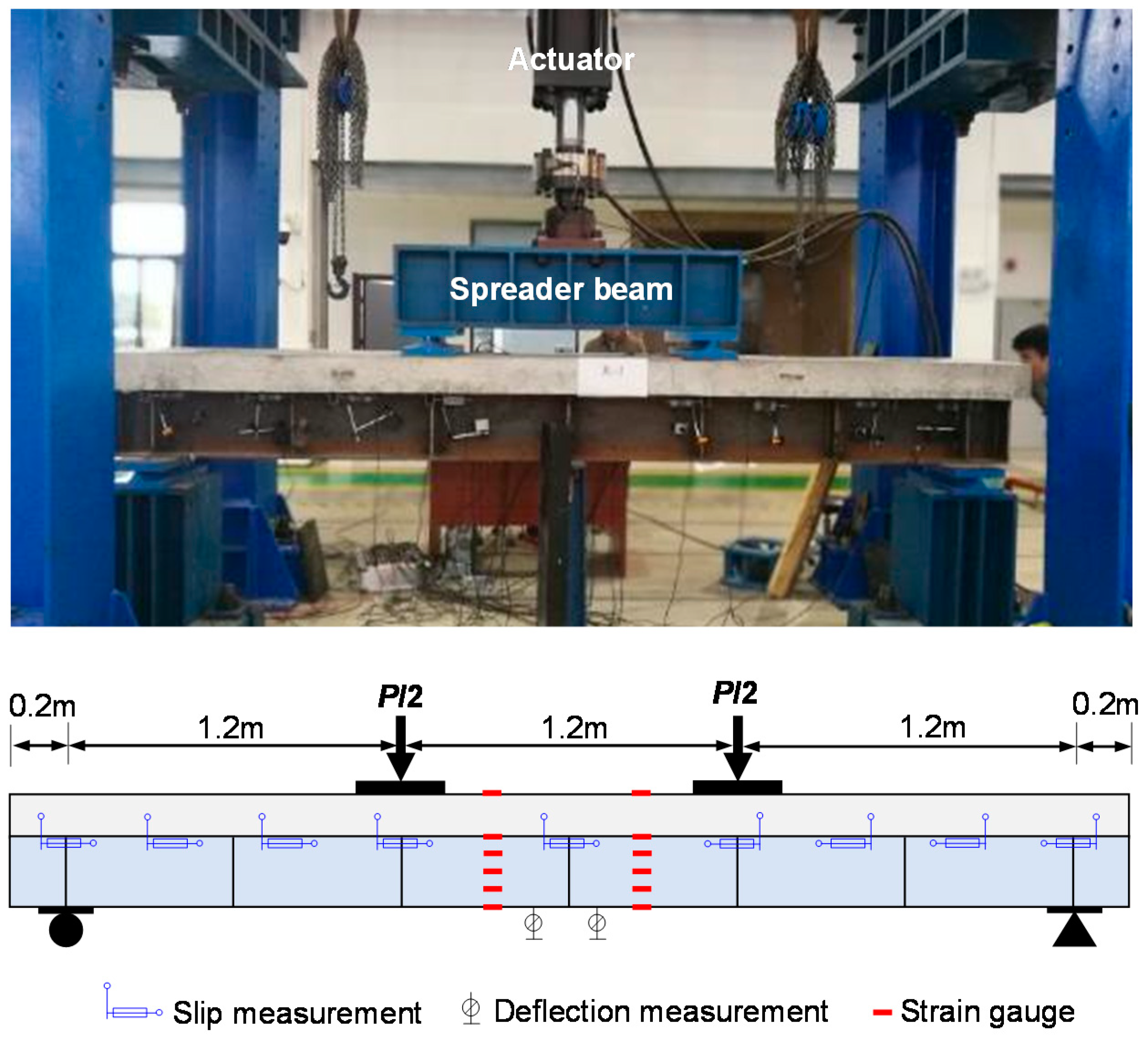
2.3.2. Test Set-Up and Instrumentation

Figure 6 shows the experimental set-up used for both the static and fatigue tests of the composite beam models. The tests were performed with a four-point flexural loading configuration. During the static tests for Beam 1 and Beam 2, loading was applied in increments of approximately 20 kN prior to the yielding of the steel girder. After that, loading was continued in displacement control at a speed of 2 mm per stage. Beam 3 was exposed to 2,000,000 cycles of cyclic loads at 3 Hz. The maximum and minimum cyclic loads were respectively 0.3Pu and 0.5Pu, where Pu is the ultimate failure load of the composite beam.
As shown in Figure 6, strain gauges were used to monitor the normal strains on critical sections and linear variable displacement transducers (LVDTs) were installed to measure the vertical deflections of the composite beam models. Mechanical dial indicators were installed along the beam for monitoring the steel-concrete interlayer load-slip relationship.

3. Results and Discussions

3.1. Push-Out Testing of Shear Connectors

According to the previous study of Papastergiou and Lebet [10], there are two primary types of failure for the embossed steel-cement grout interface: bearing failure and shear failure. In the current push-out tests, three specimens all failed along the embossed steel-UHPC-grout interface (Interface 2). Obvious relative slip occurred between the embossed steel plate and the UHPC-grout (Figure 7), while no obvious cracks appeared in the specimens.
Figure 8 shows the shear stress–slip curves of the push-out tests. All specimens exhibited similar load-slip behavior. The slip was primarily from the interface between the embossed steel rib and the UHPC grout. The ultimate shear resistance of the UHPC-grout strip shear connection (τu) is 15 MPa, and the residual frictional resistance (τfr) is roughly 9 MPa. Figure 8 also shows the typical load-slip behavior of the specimens tested by Diógenes et al. [11], which were grouted by High-Performance Mortar (HPM) with an average compressive strength of 80 MPa. As can be seen, the use of UHPC as the connection grout exhibited a significant increase in ultimate shear resistance compared to HPM, mainly attributing to the better mechanical properties of UHPC over traditional cementitious grouts.

3.2. Static Testing of Composite Beam 1 and Beam 2

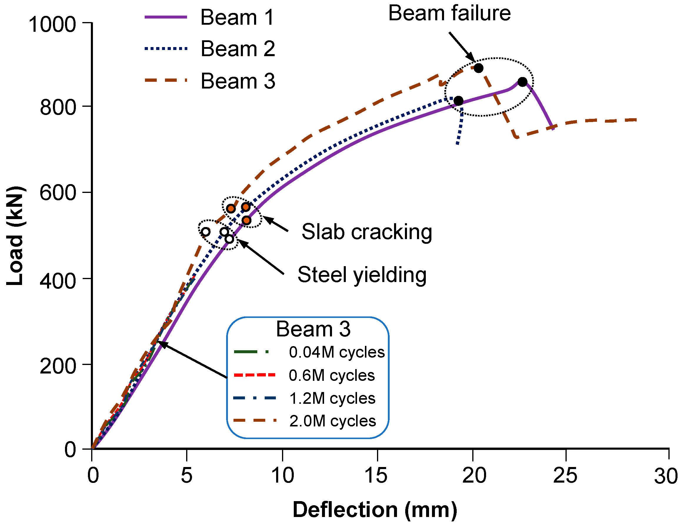
3.2.1. Load-Deflection Relationship and Failure Mode

Figure 9 shows the load-deflection curves at the midspan obtained from the static tests. Both composite beams behaved in a linear elastic manner until the supporting steel beam started to yield at a strain of 1250 με. Simultaneously, cracks began to appear on the precast concrete slab at the locations of loading plates. The final collapse of the composite beams was caused by the failure of the shear connection, where vertical cracks were observed at the beam ends. The ultimate loads of Beam 1 and Beam 2 are 845 kN and 810 kN, respectively. The ultimate midspan deflection is above 20 mm (i.e., l0/180, where l0 is the span length), indicating that the structural performance of the beam is ductile (Figure 10).

3.2.2. Composite Action

Figure 11 shows the longitudinal strain distributions over the beam depth at mid-span for Beam 1. As expected, the plane-section assumption is well satisfied in the elastic stage. Although inconsistencies can be seen in the plastic stage, it can be observed that effective composite action was developed between the deck slab and the steel girder up to failure. As can be seen from Figure 11, the theoretical location of the neutral axis is close to that identified from the test results. Once again, it can be concluded that an effective composite action was developed between the precast slab and the steel girder. When the load is increased to 800 kN, the longitudinal strain distribution over the mid-span section is not linear. This indicates that interface slippage occurred between the precast slab and the supporting steel girder.

3.2.3. Load–Slip Relationship

Figure 12 shows the load–slip relationships obtained for the test specimens. The slip between the concrete and steel was measured by mechanical dial indicators along the beam. At failure, a maximum slip of 0.5 mm was observed, which is identical to the result of the push-out specimens shown in Figure 8. The steel–concrete interfaces with the maximum slip were in the middle of the shear spans. As the applied load increased, the maximum slip increased nonlinearly.

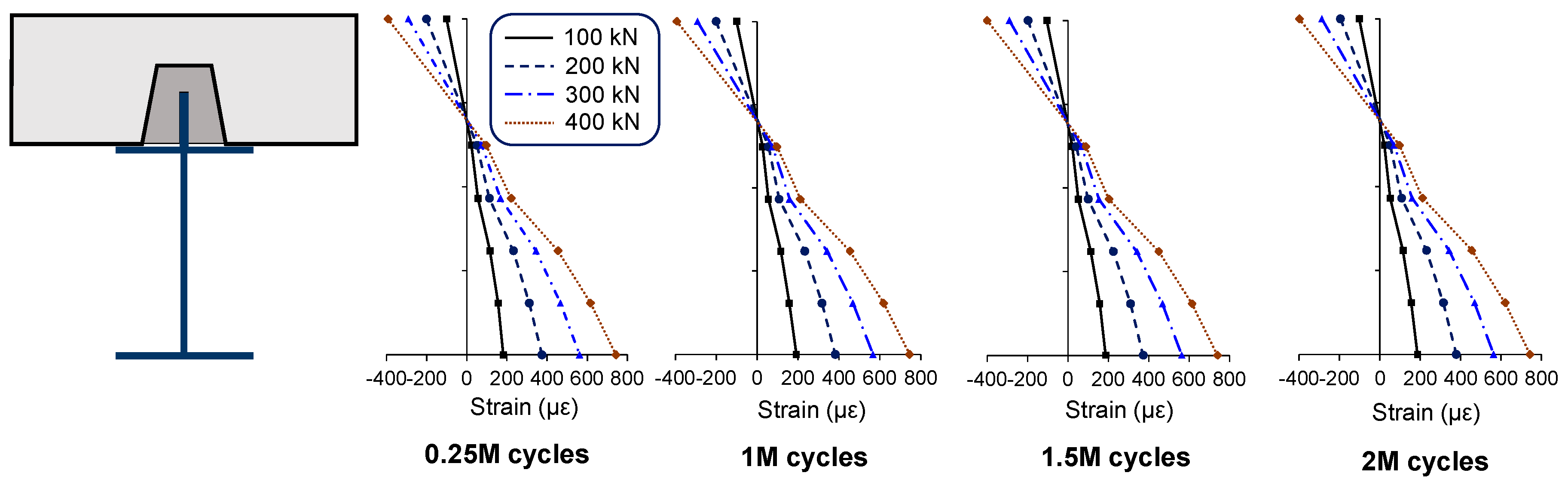
3.3. Fatigue Testing of Composite Beam 3

Beam 3 was tested with a cyclic loading followed by a static test to failure. The cyclic loading corresponds to a variation of 0.3Pu to 0.5Pu, where Pu is the ultimate load capacity of composite Beams 1 and 2.
Figure 13 shows the distributions of longitudinal strain over the beam depth at the mid-span after a specified number of load cycles. As can be seen, the composite action remained intact after testing for 2 million load cycles. After the cyclic load tests, Beam 3 was loaded to failure. Figure 14 shows the load-defection curve of Beam 3, together with the curves of Beam 1 and Beam 2. As can be seen, the fatigue loading has no damage effect on the structural performance of the composite beam.

4. Theoretical Analysis and Comparison

4.1. Evaluation of the Degree of Shear Connection

Composite beams are classified as fully composite and partially composite based on the degree of shear connection [22]. In the plastic approach adopted by the AASHTO and AISC specifications, it is assumed that the horizontal shear is distributed evenly along the interface (Figure 15). To develop a full interaction, the required horizontal shear (Vh*) along the interface between the concrete slab and the steel beam shall be:
Vh* = min {Asfy, 0.85Acfc},
where As is the area of the steel beam; fy is the yield strength of the steel beam; fc is the compressive strength of the concrete; and Ac is the effective area of the concrete slab.
Meanwhile, the actual shear force (Vh) provided by the UHPC-grout strip shear connection along the shear span is given as:
Vh = 2hp·av·τu,
where τu is the interface shear strength of the UHPC-grout strip shear connection, which can be taken as 15 MPa according to the pull-out tests; hp is the height of the embossed steel plate; and av is the length of the shear span.
The degree of shear connection is defined as:
η = Vh/Vh*.
If η is greater than or equal to 1, the beam is said to be a “full composite beam.” Otherwise, the beam is said to be a “partially composite beam.” For the composite beams tested in this study, Vh* is calculated as min{7512 × 250 × 10−3, 0.85 × 66,000 × 57.8 × 10−3} = min{1878, 3243} = 1878 kN, and Vh is calculated as 2 × 0.06 × 1.2 × 15 × 103 = 2160 kN. Therefore, the degree of shear connection is η = 2160/1878 = 1.15, which indicates that the tested beams are “full composite.”
In the tests, all three beams exhibited a sudden loss of load capacity due to the failure of the shear connection. As shown in Figure 15, the actual distribution of horizontal shear stresses along the interface slightly deviates from the uniform-distribution assumption in the plastic analysis. The maximum shear stress is roughly 15% larger than the average value. This provides a reasonable explanation for the failure mode of the tested beams.

4.2. Evaluation of Plastic Resistance Moment

For a full composite beam, the plastic resistance moment of the composite cross-section can be calculated based on the sectional analysis by CEN [23]. The calculation result in Figure 16 shows that the plastic neutral axis of the cross-section lies in the concrete slab. The depth of the neutral axis is given as:
x = Asfy/0.85bfc = 83.9 mm,
where As is the area of the steel beam and the embossed steel plate and b is the effective width of the concrete slab.
Therefore, the plastic resistance moment of the composite cross-section is obtained as:
Mu = Asfy(hhs/2 − x/2) = 480 kN·m,
where h is the overall height of the composite beam and hs is the height of the steel beam.
In the tests of Beam 1 and Beam 2, the experimental moment strengths are 507 kN·m and 489 kN·m, which are slightly higher than the above prediction (i.e., 480 kN·m).

5. Finite Element Modelling

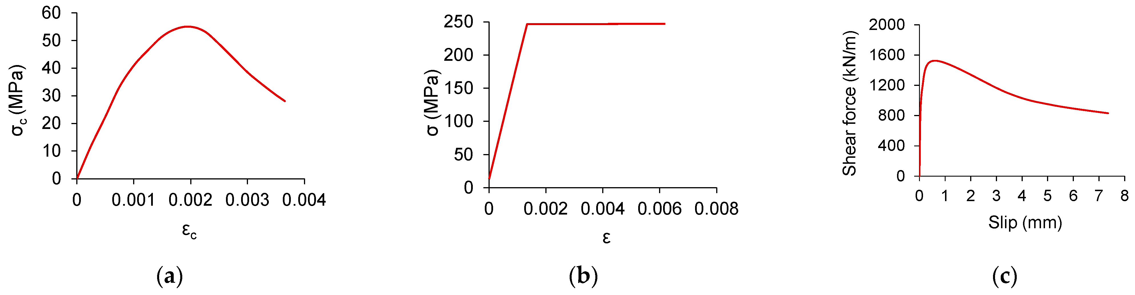
5.1. Finite Element Model

Three-dimensional stress analysis was conducted using the software ANSYS (Release 10.0). Figure 17 shows the finite element (FE) model, in which the concrete was modelled by eight-node solid elements (SOLID 65); steel girder and steel rib were modelled by four-node shell elements (SHELL 43); and UHPC grouting shear connections were modelled by spring elements (COMBIN 39). The constitutive relationship of concrete and steel were adopt as shown in Figure 18a,b. The shear stress–slip constitutive relationship of UHPC grouting material (Figure 18c) was adopted from the direct shear tests by Thomann et al. [13] and Papastergiou [14].

5.2. Comparisons between FEA and Test Results

Figure 19a shows the load-deflection relationship curves of test beams and FE simulation and Figure 19b gives the distribution of interface slip at the load of 800 kN. In the elastic and plastic stage, the load-deflection curve of the finite element simulation is in good agreement with that of test results, which shows that the shear behavior of composite beams with UHPC grouting material can be well simulated. The maximum relative slip of Beam 1, Beam 2 and FE modelling are 0.53 mm, 0.44 mm, and 0.46 mm respectively, with a high degree of coincidence. The maximum slip occurs at approximate 800 mm away from the bearing instead of at loading points or at the bearing. This could possibly be because the complex stress condition makes the slip stiffness of loading points or at the bearing increase.
Figure 20 shows the comparison of strain distribution of FE simulation and test results. During the loading process, the experimental and theoretical variation of strain agree well with each other at both the top of the concrete slab and the bottom of the steel girder.

6. Design of a Prototype Bridge

To facilitate future applications in bridge engineering, a trial design of a steel-concrete composite bridge using the UHPC-grout strip shear connection is presented here. The prototype bridge is designed in accordance with AASHTO [24].

6.1. Details of the Prototype Bridge

As illustrated in Figure 21, the prototype bridge has a simply-supported span of 35 m with a 12.4 m wide deck. The bridge carries two standard 3.75 m traffic lanes and a 3.4 m wide urgency parking strip. Precast panels 2–3 m wide are transversely connected by preformed shear key joints. The structural steel used for the main beams, stiffeners and cross bracing conforms to ASTM A709 Grade 345. The deck concrete has a minimum 28 day compressive strength of 40 MPa. The UHPC-grout has a minimum 28 day compressive strength of 120 MPa, and 1.5% high-strength steel fibers by volume.
Figure 22 shows typical cross-sections for the composite bridge at midspan and support. The superstructure consists of four steel I-girders with a full-depth precast concrete deck. The deck is 380 mm thick above the main beams and 220 mm thick at its center. The steel girders are 1.6 m deep and are spaced at 3.2 m center to center.
Figure 23 shows the details of the UHPC-grout strip shear connection. The grouting channel pre-formed in the slab has a trapezoidal-shaped cross-section. The depth of the grouting channel is 120 mm. The embossed steel plate for the shear connection has a thickness of 12 mm and a depth of 115 mm. It is roughed by 45° oriented grooves (2 mm deep and 40 mm wide) and is drilled with circular holes (40 mm diameter and 150 mm spacing).

6.2. Demand for Interface Shear

According to AASHTO [24], the nominal horizontal shear (Vh*) between the mid-span and the support shall be taken as:
Vh* = min {Asfy, 0.85Acfc} = 24,807 kN,
where As is the area of the steel beam (71,904 mm2); fy is the yield strength of the steel beam (345 MPa); fc is the compressive strength of the concrete (40 MPa); and Ac is the effective area of the concrete slab (0.832 m2).
The nominal shear resistance (Vh*) provided by the UHPC-grout strip shear connection along the shear span is given as:
Vh = Vn·l0/2 = 31,500 kN,
where Vn is the nominal shear resistance of the UHPC grout strip shear connection, which can be taken as 1800 kN/m according to composite beam tests; and l0 is the span length.
Therefore, the degree of shear connection is:
η = Vh/Vh* = 1.27.
The above result shows that the UHPC grout strip shear connection has the potential to meet the requirements for horizontal shear in the design of a real bridge.

6.3. Construction Process

Figure 24 shows the major construction stages of the prototype bridge, including (1) erection of steel girders and cross frames; (2) erection of precast deck panels; (3) field casting of panel-to-panel joints; (4) grouting of UHPC to the connection channel; and (5) casting of deck surfacing layer.

6.4. Discussions

The trail design of the prototype bridge shows that the UHPC-grout strip shear connection has the potential to be used in accelerated bridge construction. It is believed that the UHPC-grout strip shear connection is a promising option for the design of steel–concrete composite bridges. However, more research should be carried out, especially in relation to fatigue behavior under vehicular loading and the response under long-term loading.

7. Conclusions

An enhanced strip shear connection using UHPC as the grout has been developed for the prefabricated steel–concrete composite bridge system. Push-out tests of shear connectors and static and fatigue tests of composite beams were conducted to validate the performance of the new connection. The following conclusions can be drawn:
  • Based on the push-out testing, the ultimate capacity of the shear connection was dominated by the interface failure between the embossed steel and the UHPC grout. The interface shear strength of the UHPC grout strip shear connection could be as high as 15 MPa. The use of UHPC as the connection grout exhibited a significant increase in capacity compared to HPM.
  • Based on the static testing of composite beams, the UHPC-grout strip shear connection exhibited good interface shear performance. Full composite action was developed between the precast panels and steel beams in the composite beams.
  • Based on the fatigue testing of a composite beam, the composite action remained intact after testing for two million load cycles, and the fatigue loading had no damaging effect on the structural performance of the composite beam.
  • Both the experimental tests and theoretical calculations showed that a full interaction could be developed between the precast panels and steel beams. The ultimate capacity of the composite beam using the UHPC grout strip shear connection could be well predicted by the plastic approach. In the tests of Beam 1 and Beam 2, the experimental moment strengths are 507 kN·m and 489 kN·m, respectively, which are close to the theoretical moment strength of 480 kN·m predicted by the plastic approach.
  • The trail design of the prototype bridge shows that the UHPC grout strip shear connection has the potential to be used in accelerated bridge construction. Calculation results indicate that this novel connection has the potential to meet the requirements for horizontal shear in the design of a real bridge.

Author Contributions

Conceptualization, Z.-Q.H.; methodology, Z.-Q.H.; software, C.O.; validation, Z.-Q.H. and F.T.; formal analysis, Z.-Q.H.; investigation, Z.-Q.H. and C.O.; resources, Z.L.; data curation, C.O. and F.T.; writing—original draft preparation, Z.-Q.H.; writing—review and editing, Z.-Q.H. and Z.L.; visualization, F.T.; supervision, Z.L.; project administration, Z.L.; funding acquisition, Z.-Q.H. and Z.L. All authors have read and agreed to the published version of the manuscript.

Funding

This research was funded by the National Key R&D Program of China, grant number 2019YFE0119800; the National Natural Science Foundation of China, grant number U1934205 and 51778137; and the Outstanding Youth Foundation of Jiangsu Province, China, grant number BK20180063.

Institutional Review Board Statement

Not applicable.

Informed Consent Statement

Not applicable.

Data Availability Statement

The authors confirm that the data supporting the findings of this study are available within the article.

Conflicts of Interest

The authors declare no conflict of interest.

References

  1. Shim, C.S.; Lee, P.G.; Chang, S.P. Design of shear connection in composite steel and concrete bridges with precast decks. J. Constr. Steel Res. 2001, 57, 203–219. [Google Scholar] [CrossRef]
  2. Issa, M.A.; Patton, T.A.; Abdalla, H.A.; Yousif, A.A.; Issa, M.A. Composite behavior of shear connections in full-depth precast concrete bridge deck panels on steel stringers. PCI J. 2003, 48, 76–89. [Google Scholar] [CrossRef]
  3. Badie, S.S.; Girgis, A.; Tadros, M.K.; Nguyen, N.T. Relaxing the stud spacing limit for full-depth precast concrete deck panels supported on steel girders (phase I). J. Bridge Eng. 2010, 15, 482–492. [Google Scholar] [CrossRef]
  4. Badie, S.S.; Girgis, A.; Tadros, M.K.; Sriboonma, K. Full-scale testing for composite slab/beam systems made with extended stud spacing. J. Bridge Eng. 2011, 16, 653–661. [Google Scholar] [CrossRef]
  5. Huh, B.; Lam, C.; Tharmabala, B. Effect of shear stud clusters in composite girder bridge design. Can. J. Civ. Eng. 2015, 42, 259–272. [Google Scholar] [CrossRef]
  6. Xu, C.; Sugiura, K.; Masuya, H.; Hashimoto, K.; Fukada, S. Experimental study on the biaxial loading effect on group stud shear connectors of steel-concrete composite bridges. J. Bridge Eng. 2015, 20, 04014110. [Google Scholar] [CrossRef]
  7. He, Z.Q.; Xu, T.; Xing, Y.; Liu, Z.; Ma, Z.J. Overlap of splitting in slabs with closely spaced intermediate anchorages. J. Bridge Eng. 2020, 25, 04020045. [Google Scholar] [CrossRef]
  8. Ovuoba, B.; Prinz, G.S. Headed shear stud fatigue demands in composite bridge girders having varied stud pitch, girder depth, and span length. J. Bridge Eng. 2018, 23, 04018085. [Google Scholar] [CrossRef]
  9. Thomann, M. Connexions par Adhérence Pour les Ponts Mixtes Acier-Béton. Ph.D. Thesis, École Polytechnique Fédérale de Lausanne (EPFL), Lausanne, Switzerland, 2005. [Google Scholar]
  10. Papastergiou, D.; Lebet, J.P. Experimental investigation and modelling of the structural behavior of confined grouted interfaces for a new steel-concrete connection. Eng. Struct. 2014, 74, 180–192. [Google Scholar] [CrossRef]
  11. Diógenes, H.J.F.; Debs, A.E.; Valente, I.B. Experimental analysis of new interfaces for connections by adhesion, interlocking and friction. J. Constr. Steel Res. 2015, 110, 170–181. [Google Scholar] [CrossRef] [Green Version]
  12. Diógenes, H.J.F.; Debs, A.E.; Valente, I.B. Tests on composite beams using new connections by adherence. Proc. Inst. Civ. Eng. Struct. Build. 2018, 171, 149–165. [Google Scholar] [CrossRef]
  13. Thomann, M.; Lebet, J.P. The modelling of an embossed steel-to-cement paste confined interface loaded in shear. J. Constr. Steel Res. 2007, 63, 639–646. [Google Scholar] [CrossRef]
  14. Papastergiou, D. Connections by Adhesion, Interlocking and Friction for Steel-Concrete Composite Bridges under Static and Cyclic Loading. Ph.D. Thesis, École Polytechnique Fédérale de Lausanne (EPFL), Lausanne, Switzerland, 2012. [Google Scholar]
  15. Graybeal, B.A.; Bruhwiler, E.; Kim, B.S.; Toutlemonde, F.; Voo, Y.L.; Zaghi, A. International perspective on UHPC in bridge engineering. J. Bridge Eng. 2020, 25, 04020094. [Google Scholar] [CrossRef]
  16. Graybeal, B.A. Ultra-High Performance Concrete Composite Connections for Precast Concrete Bridge Decks; Report No. FHWA-HRT-12-041; Federal Highway Administration. Office of Infrastructure Research and Development: Washington, DC, USA, 2012. [Google Scholar]
  17. He, S.; Fang, Z.; Mosallam, A.S. Push-out tests for perfobond strip connectors with UHPC grout in the joints of steel-concrete hybrid bridge girders. Eng. Struct. 2017, 135, 177–190. [Google Scholar] [CrossRef]
  18. Kruszewski, D.; Wille, K.; Zaghi, A.E. Push-out behavior of headed shear studs welded on thin plates and embedded in UHPC. Eng. Struct. 2018, 173, 429–441. [Google Scholar] [CrossRef]
  19. Wang, J.; Qi, J.; Tong, T.; Xu, Q.; Xiu, H. Static behavior of large stud shear connectors in steel-UHPC composite structures. Eng. Struct. 2019, 178, 534–542. [Google Scholar] [CrossRef]
  20. Haber, Z.B.; Graybeal, B.A.; Nakashoji, B. Ultimate behavior of deck-to-girder composite connection details using UHPC. J. Bridge. Eng. 2020, 25, 04020038. [Google Scholar] [CrossRef]
  21. He, Z.Q.; Tian, F.; Zheng, H.F. New Shear Connections Using UHPC for Prefabricated Composite Bridges; Report No. 2015-ZJKJ-PTJS01; Southeast University: Nanjing, Jiangsu, China, 2017. [Google Scholar]
  22. Yura, J.A.; Methvin, E.R.; Engelhardt, M.D. Design of Composite Steel BEAMS for Bridges; Report No. FHWA/TX-08/0-4811-1; The University of Texas at Austin: Austin, TX, USA, 2008. [Google Scholar]
  23. BS EN. Design of Composite Steel and Concrete Structures Part 2: General Rules and Rules for Bridges; CEN: Brussels, Belgium, 2005. [Google Scholar]
  24. AASHTO. AASHTO LRFD Bridge Design Specifications; AASHTO: Washington, DC, USA, 2017. [Google Scholar]
Figure 1. Schematic of full-depth precast concrete deck panel system.
Buildings 11 00182 g001
Figure 2. Schematic of strip shear connection: (a) general view; (b) interface details.
Buildings 11 00182 g002
Figure 3. General details of push-out specimens (dimensions in mm): (a) elevation view; (b) plane view; (c) roughness treatment.
Buildings 11 00182 g003
Figure 4. General details of composite beam specimens (dimensions in mm): (a) elevation view; (b) cross section (c) plane view; (d) beam segment.
Buildings 11 00182 g004
Figure 5. Fabrication of composite beam specimens: (a) welding of embossed steel plate; (b) casting of precast slab; (c) sand-blasting; (d) grouting from pockets.
Buildings 11 00182 g005
Figure 6. Test set-up and instrumentation of composite beam specimens.
Buildings 11 00182 g006
Figure 7. Slip between embossed steel plate and UHPC grout.
Buildings 11 00182 g007
Figure 8. Comparison of shear stress–slip behaviors of the specimen tested by Diógenes et al. [11] and the ones tested in this study.
Buildings 11 00182 g008
Figure 9. Static testing results of Beam 1 and Beam 2: (a) load-deflection curves; (b) failure mode.
Buildings 11 00182 g009
Figure 10. Deformation capacity of Beam 2 at failure.
Buildings 11 00182 g010
Figure 11. Longitudinal strain distributions over mid-span section of Beam 1.
Buildings 11 00182 g011
Figure 12. Interface slip at different loading stages: (a) results of Beam 1; (b) results of Beam 2.
Buildings 11 00182 g012
Figure 13. Longitudinal strain distributions over mid-span section of Beam 3.
Buildings 11 00182 g013
Figure 14. Load-deflection curves of composite beams.
Buildings 11 00182 g014
Figure 15. Distribution of horizontal shear stresses along steel–concrete interface.
Buildings 11 00182 g015
Figure 16. Sectional analysis for plastic resistance moment.
Buildings 11 00182 g016
Figure 17. Three-dimensional FE model of composite beam: (a) general view of the FE model; (b) simulation of shear connections.
Buildings 11 00182 g017
Figure 18. Constitutive relationship: (a) concrete; (b) steel; (c) UHPC grouted shear connection.
Buildings 11 00182 g018
Figure 19. Comparison of test and FE results: (a) load-deflection relationship; (b) interface slip of steel and concrete at a load of 800 kN.
Buildings 11 00182 g019
Figure 20. Comparison of strain: (a) strain at the bottom of the steel beam; (b) strain at the top of the concrete slab; (c) strain distribution on sections at the load of 200 kN; (d) strain distribution on sections at the load of 800 kN.
Buildings 11 00182 g020
Figure 21. Schematic of the prototype bridge.
Buildings 11 00182 g021
Figure 22. Typical cross sections at midspan and support (dimensions in mm).
Buildings 11 00182 g022
Figure 23. Details of the UHPC grout strip shear connection (dimensions in mm): (a) plane view of precast deck panel; (b) details of grouting channel; (c) details of grouting pocket; (d) details of embossed steel plate.
Buildings 11 00182 g023aBuildings 11 00182 g023b
Figure 24. Major construction stages of the prototype bridge.
Buildings 11 00182 g024
Table 1. Relative weight ratios to cement in the mix design.
CementFine SandSilica FumeHigh Active AdmixtureSuperplasticizerSteel Fiber Water
1.01.10.250.280.050.220.2
Table 2. Material properties for composite beam specimens.
ComponentMaterial GradeMaterial Properties
Steel plateQ235Bfy = 250 MPa
Concrete slabC50fc = 57.8 MPa (28 days)
GroutUHPCfc = 125.6 MPa (28 days)
Mild steel rebarHRB400fy = 415 MPa
Note: fy is the yield strength of steel; fc is the cylinder compressive strength of concrete.
Publisher’s Note: MDPI stays neutral with regard to jurisdictional claims in published maps and institutional affiliations.

