Lubrication Analysis of Micro-Dimple Textured Die Surface by Direct Observation of Contact Interface in Sheet Metal Forming


1
Division of Mechanical Systems Engineering, Graduate School of System Design, Tokyo Metropolitan University, Japan 6-6, Asahigaoka, Hino, Tokyo 191-0065, Japan
2
Faculty of Production Engineering-Mechanical Engineering & Process Engineering, University of Bremen, Bibliothekstraße 1, 28359 Bremen, Germany
*
Author to whom correspondence should be addressed.
Metals 2019, 9(9), 917; https://doi.org/10.3390/met9090917
Submission received: 16 July 2019
/
Revised: 8 August 2019
/
Accepted: 15 August 2019
/
Published: 22 August 2019
(This article belongs to the Special Issue Metal Micro-forming)
Abstract
:To investigate the underlying mechanism of the effects of surface texturing on lubricated sliding friction in the metal forming operation, an in-situ observation system using transparent silica glass dies and a high speed recording camera was newly developed. To correlate the dimensional parameters of micro-dimple textured structures and tribological properties in the metal forming operation, the in-situ observation was performed during bending with the ironing process of the stainless steel sheet with a thickness of 0.1 mm. The lubrication behavior were compared between the different lubricant viscosities and the micro-dimple textures with different diameters of 10 µm, 50 µm, 100 µm fabricated by using femto-/pico-second laser processing. As a result, the textured die with dimple diameters of 10 µm and 50 µm showed the lubricant flow transferred from one to the other dimples owing to the lubricant reservoir effect, while that of 100 µm indicated the less supply of the lubricant. However, the textured die with a dimple diameter of 10 µm demonstrated higher ironing force than that of 50 µm, due to the severe adhesion of work materials inside the dimple structures. Based on these experimental findings, the dimple size dependencies on lubricant reservoirs effects and the generation of the hydrodynamic pressure were discussed by correlating with the in-situ observation results, a fluid-flow analysis and a laminar two-phase flow analysis using the finite element method.
1. Introduction
Surface texturing has attracted a great attention as a geometrical modification approach to improve tribological performances in the metal forming operation [1]. In particular, the development of laser processing technology has expanded its possibility in applying micro-textured array patterns on complex three-dimensional structures. Although the initial studies were mainly focused on the surface texturing of random dimple patterns on work materials, e.g., by shot-blast texturing [2] or by electrical discharge texturing [3], research activities are gradually shifting either for the application to metal forming tools within a great advancement in efficiency and varieties of laser processing [4].
Geiger et al. applied the micro-texture surface by using an excimer laser radiation onto a TiN coated cold forging tool surface. They have shown the significant improvement of tool life by applying the surface texture [5]. Costa and Hutchings investigated the effect of surface texturing by strip drawing tests under a lubricated sliding contact including plastic deformation of stainless steel work sheets. The impact of groove orientation to the drawing direction was demonstrated indicating the significant decrease of the coefficient of friction when it oriented perpendicularly to the drawing direction [6]. Xu et al. applied the micro-channel patterns by using laser surface texturing, and demonstrated the friction reduction during the single point incremental forming process [7].
General understanding for the functions of surface textures is the creation of the load carrying capacity owing to the hydrodynamic lift effect [8]. In addition, it acts as a lubricant reservoir, which enhances the lubricant entrainment and retention under boundary lubrication [9]. Moreover, it is also known as the structure for the wear debris entrapment to minimize the effect on damaging to the contact pair [10]. However, these effects are strongly dependent on the contact state and operating conditions, so that the optimal geometrical parameters for the design of surface texturing patterns are still under discussion.
In view of the design of surface texturing patterns, one of the most commonly used geometrical patterns are circular dimple structures sized in the range from a few microns to hundreds of microns [11]. In particular, dimple diameters, texture densities, and the relative dimple depth are the important design parameters for surface textures in contact. Most of the studies have been contributed to find optimal values for those parameters to obtain the best tribological performance to achieve the maximum load carrying capacity under hydrodynamic lubrication [12]. In comparison with the conventional studies in the field of tribology for bearing [13] or automotive piston [14], characteristic features of the contact state in metal forming is the contact pair loaded under plastic deformation. Thus, the amount of strain induced in the work material will strongly affect the real area of contact and so as the lubrication between tools and materials [15]. In such a contact state, it is well known that the role of the plasto-hydrodynamic lubrication (PHL) becomes dominant under certain specific contact conditions [16]. As the surface deformation proceeds under the mixed lubrication regime, the lubricant trapped in the valley of the surface asperities act as a hydrostatic medium [17]. In particular, this increase of the effect of PHL by the intentional formation of lubricant pockets in the work material or tool surface is called the microplastohydrodynamic lubrication (MPHDL) [18]. Thus, the surface texturing patterns for the metal forming die surface should be designed based on those specific contact states. However, the basic mechanisms of the contribution of the surface texture and design guideline optimized for metal forming operations are still under discussion, due to its difficulties in observing the lubricant flow behavior between workpieces and tools.
Within these backgrounds, the present study aims to clarify the basic mechanism and relationship between the geometrical parameters of dimple surface textures and lubrication properties during metal forming operations. In sheet metal forming, for example, the surface is loaded under contact pressure from few hundreds of MPa in the deep drawing process to more than 1 GPa such as for the ironing process, with the ratio of surface enlargement less than 2% [19]. As a first approach to investigate under these contact states, the in-situ observation system using transparent silica glass dies and a high speed recording camera was developed to directly observe the dynamic variation of the contact interface during ironing of the sheet material under the mixed lubrication regime. To correlate the dimensional parameters of surface textures and tribological properties, micro-dimple array patterns were fabricated on silica glass dies by using femto-/pico-second laser processing. By using this laser surface textured silica glass die, the in-situ observation was performed during ironing of the stainless steel sheet with a thickness of 0.1 mm. The difference in the lubricant flow behavior and its effect on the tribological properties between the different dimple structures under the different contact state was thoroughly investigated.
2. Experimental
2.1. Development of In-Situ Observation System
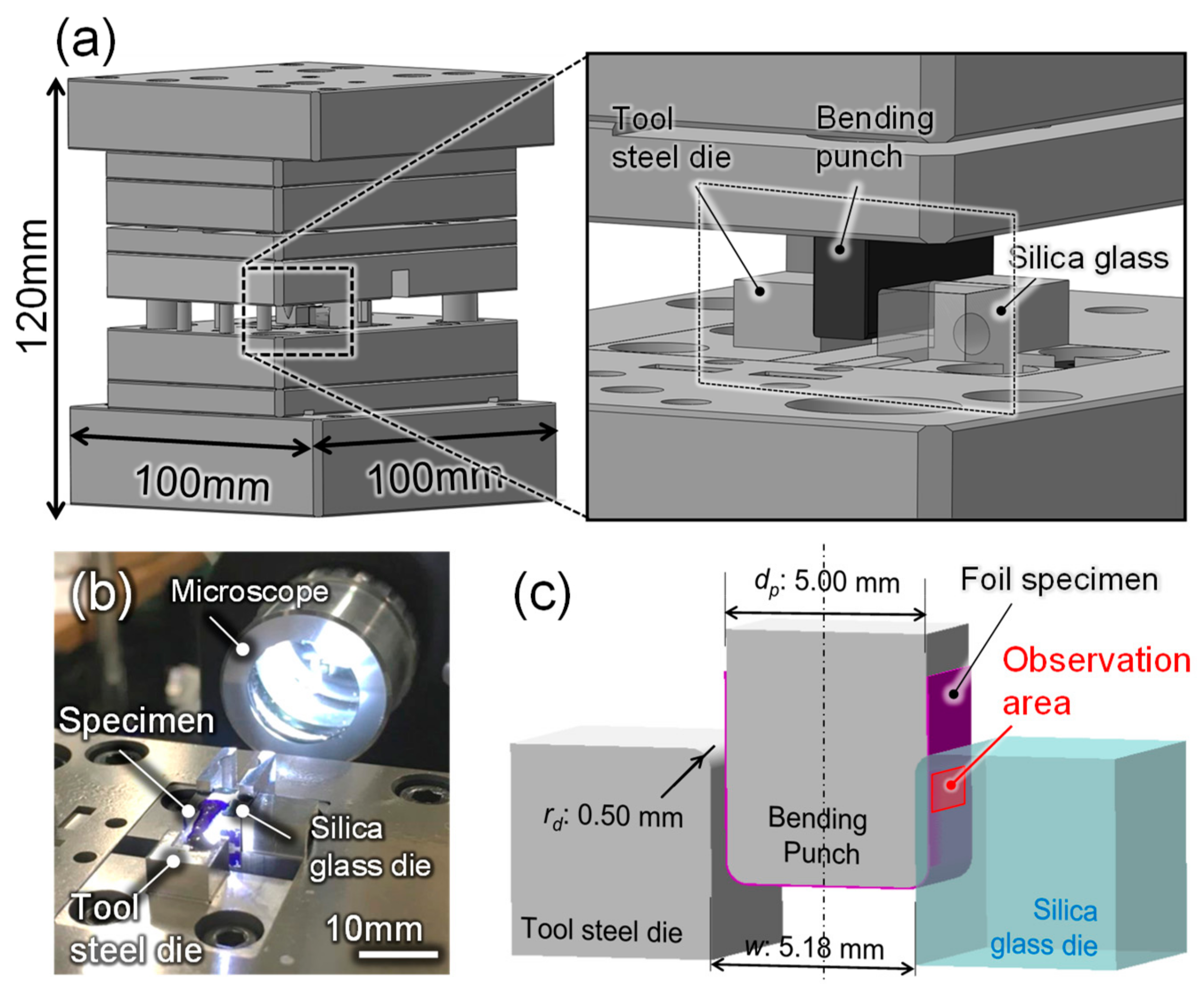
A new in-situ observation system was developed with a high-speed recording camera system, VW-9000, equipped with a microscope lens VH-Z75 (Keyence Corp., Osaka, Japan) attached to a sheet metal forming die assembly. A load cell and a high-precision stroke sensor were built into the sheet metal forming die assembly, which enables to determine the forming load and stroke by using a data logger. The magnification of the lens can be adjusted from 75 to 750. The whole setup is installed on a high-precision desktop-size servo screw press machine, type DT-J312, Micro Fabrication Laboratory LLC. The in-situ observation system and its schematic illustration are shown in Figure 1. To observe the contact interface between the textured die and work sheet materials, a transparent silica glass die with an elastic modulus of 72 GPa was used for bending with the ironing process. An initial arithmetic mean surface roughness (Sa) of the silica glass die was 0.3 µm. The in-situ observation was achieved by observing from the back side of this silica glass die as shown in the figure. The area of the observation was decided based on the contact state analysis using the finite element (FE) analysis described in Section 3. Another bending die opposed to this silica glass die and a punch were made of tool steels (JIS: SKD11).
2.2. Fabrication of Surface Texturing
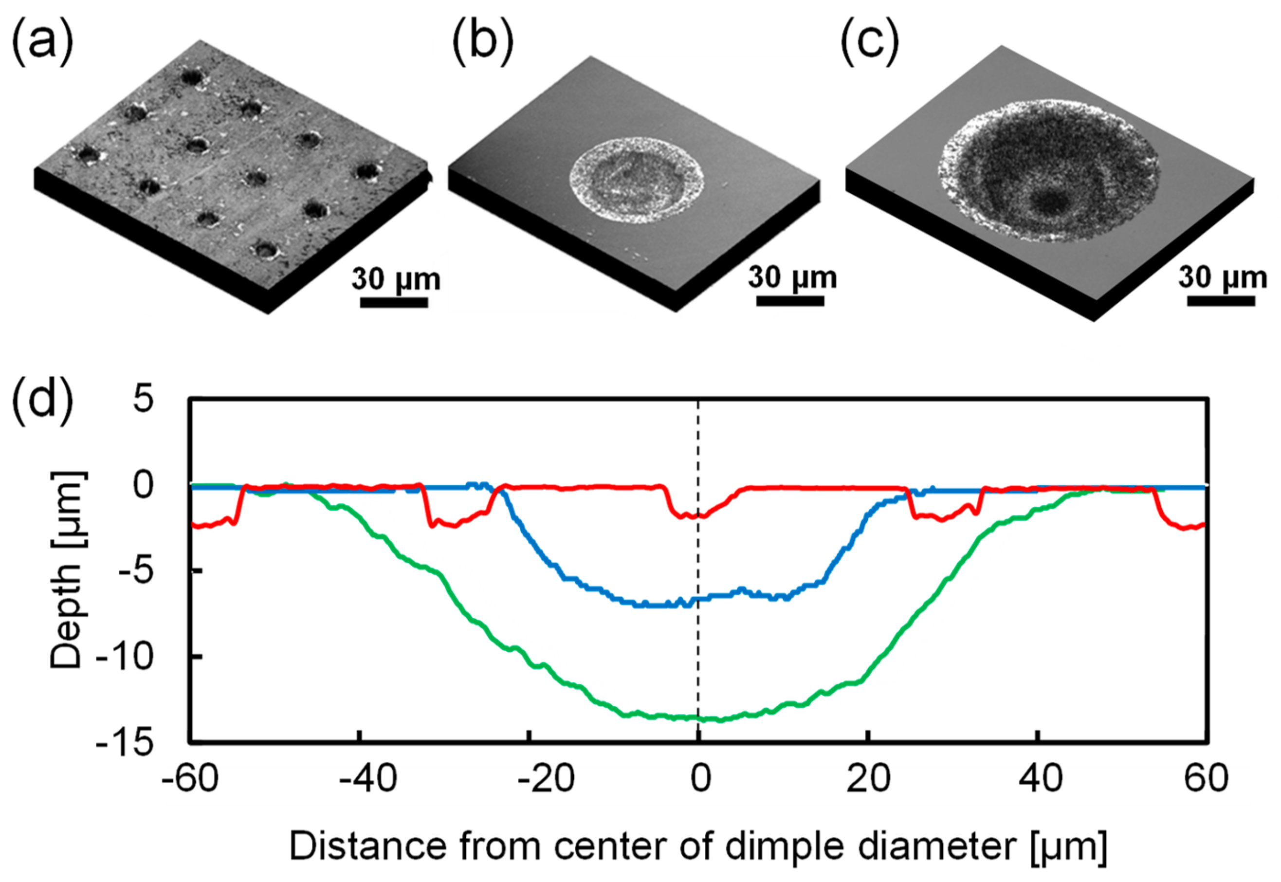
Micro-dimple array patterns were fabricated on a silica glass die surface by using the femto-/pico-second laser in view of the great advantage in its high accuracy and ability to process the µm-scale dimple textures [20]. The geometrical parameters for the micro dimple textures are summarized in Table 1. A texture density is defined as the ratio of the textured to the non-textured area. The dimple aspect ratio is defined as the ratio of the dimple depth to its diameter [11]. The micro dimple diameters were changed from 10 µm, 50 µm to 100 µm, keeping both density and aspect ratio constant. Figure 2 shows surface profiles and cross sectional profiles of dimples with different diameters fabricated by laser processing. The dimples with semi-ellipse shapes and smooth hole edges were successfully manufactured.
2.3. Experimental Conditions
Operation conditions of bending with the ironing process are summarized in Table 2. The material used was the stainless steel JIS: SUS304-H with a thickness of 0.1 mm, a width of 15 mm and a length of 3 mm. The clearance between the punch and die was set to 0.09 mm, so that the ironing was achieved for the sheet thickness of 0.1 mm. The punch velocity was 50 mm/s with a maximum stroke of 4 mm without acceleration during the process. To investigate the effect of the lubricant viscosity on the flow behavior on the textured surface, commercially available lubricants (G-6311, G-6030M, G-3116HS, Nihon Kohsakuyu Co., Ltd., Tokyo, Japan) with three different viscosities of 1.27 mm/s2, 2.53 mm/s2 and 4.51 mm/s2 were used. The in-situ observation during bending with the ironing process was carried out using silica glass dies with different dimple diameters as above. The non-textured silica glass die was also used as a reference.
3. Finite Element (FE) Simulation of Contact State
To decide the in-situ observation area along the sliding surface, the apparent contact length and contact pressure were estimated by using the FE-analysis. The analysis was done with an implicit dynamic finite element model using ABAQUS 6.16. A 2D plane-strain model was used as schematically shown in Figure 3. The mechanical properties of the work material and bending dies are summarized in Table 3 [21,22]. The model of the work sheet material was meshed with linear quadrilateral 4-node plane stress elements and was assumed as an isotropic elasto-plastic body. The material properties were obtained by uniaxial tensile tests of SUS304-H with a thickness of 0.1 mm. A total number of 77,278 elements were meshed in the whole FE model. The silica glass die and tool steel die were modeled as the elastic body and the punch was modelled as the rigid body. In the analysis, the contact state was assumed using the penalty method with a friction coefficient μ of 0.1. The validation of the simulation was confirmed by the comparison with a load-stroke curve of the non-textured silica glass die obtained by the experiment.
4. FE Based Computational Fluid Dynamics (CFD) Analysis
To analyze the lubricant flow behavior for different dimple dimensions obtained by the in-situ observation, two different CFD analyses were performed by using the COMSOL Multiphysics 5.2a. One is a laminar two-phase (air and lubricant) analysis to simulate the flow-in behavior of the lubricant to the inside of the dimple structures, and another is a fluid-flow analysis to simply simulate the steady state flow behavior during the sliding surface. Figure 4 shows a schematic illustration of the numerical model. A single unit cell of the texture patterns was chosen for the modelling domain. It consists of the moving wall at the top surface as the sliding work sheet and the lubricant film filled in between the textured tool and the work sheet. As geometrical parameters of the texture patterns, dimple diameter d, pitch b, lubricant film thickness hl were defined. To reduce the calculation time, a 2D computational domain with the textured die in cross-section was used. Details of each analysis are described in the following sections.
4.1. Laminar Two-Phase Flow Analysis
To analyze the inflow behavior of the lubricant to the inside of the dimple structure with different dimensions, the laminar two-phase flow analysis at the fluid interface between the lubricant and air was carried out. In this simulation, the phase field were time dependent since the position of the interface was dependent of its history. Two-dimensional incompressible Navier-Stokes equations were used. In addition, the Level Set method was used to describe the convection of the fluid interface. The level set function ϕ was defined below;
In a transition layer of liquid close to the interface between liquid and gas, ϕ varied smoothly from zero to one. Details for the level set function and modified Navier-Stokes equations are described elsewhere [23,24]. The sliding velocity of vw was defined at the moving wall boundary conditions of the top surface, while the bottom wall with the dimple structure are modelled as a stationary wetted wall. In addition, the lubricant inflow from the inlet at a constant flow velocity of vf was modelled and the outlet of the lubricant flow was defined as the zero gauge pressure. Table 4 summarizes the analytical conditions for the laminar two-phase flow analysis.
4.2. Fluid-Flow Analysis
To roughly estimate the generation of the hydrodynamic pressure in the steady state lubricant flow for each texture dimension during the sliding of the work sheet surface, the simple fluid flow analysis was performed. Following two-dimensional incompressible Navier-Stokes equations were used to simulate the steady state lubricant flow in between the work material and tool surface.
v is the velocity vector, p is the pressure, ρ is the mass density of the fluid and η is the viscosity of the lubricant. As well as the above laminar two-phase flow analysis, the constant velocity of v was defined as the moving wall boundary conditions of the top surface of lubricant films, while the bottom wall with dimple structure are modelled as the stationary body. In addition, the pressure at the inlet and outlet of the lubricant flow, where the end of the modelled domain of the lubricant is observed, was defined as the zero gauge pressure. Analytical conditions are summarized in Table 5.
5. Results
5.1. Contact State Analysis
Figure 5a shows a calculated result of the variation of the contact pressure and apparent contact length during bending with the ironing process for the in-situ observation. Contour figures as shown in Figure 5b show the distribution of the equivalent stress state at the corresponding punch strokes denoted in Figure 5a. The contact pressure increases with the increasing punch stroke during bending and it reaches the maximum of 1600 MPa at a stroke of 1.2 mm. Afterwards, it decreases until a stroke of 2.5 mm and it becomes almost constant until the process is completed. On the other hand, the contact length linearly increases from 0.1 mm at a stroke of 1.2 mm and it reaches the maximum contact length of 2.8 mm at a stroke of 4.0 mm. To visualize the variation in the contact state and to observe the lubricant flow of the contact interface during ironing processing, the area directly under the die radius was chosen as the in-situ observation area, where the maximum contact pressure was observed.
5.2. In-Situ Observation of Lubricant Flow
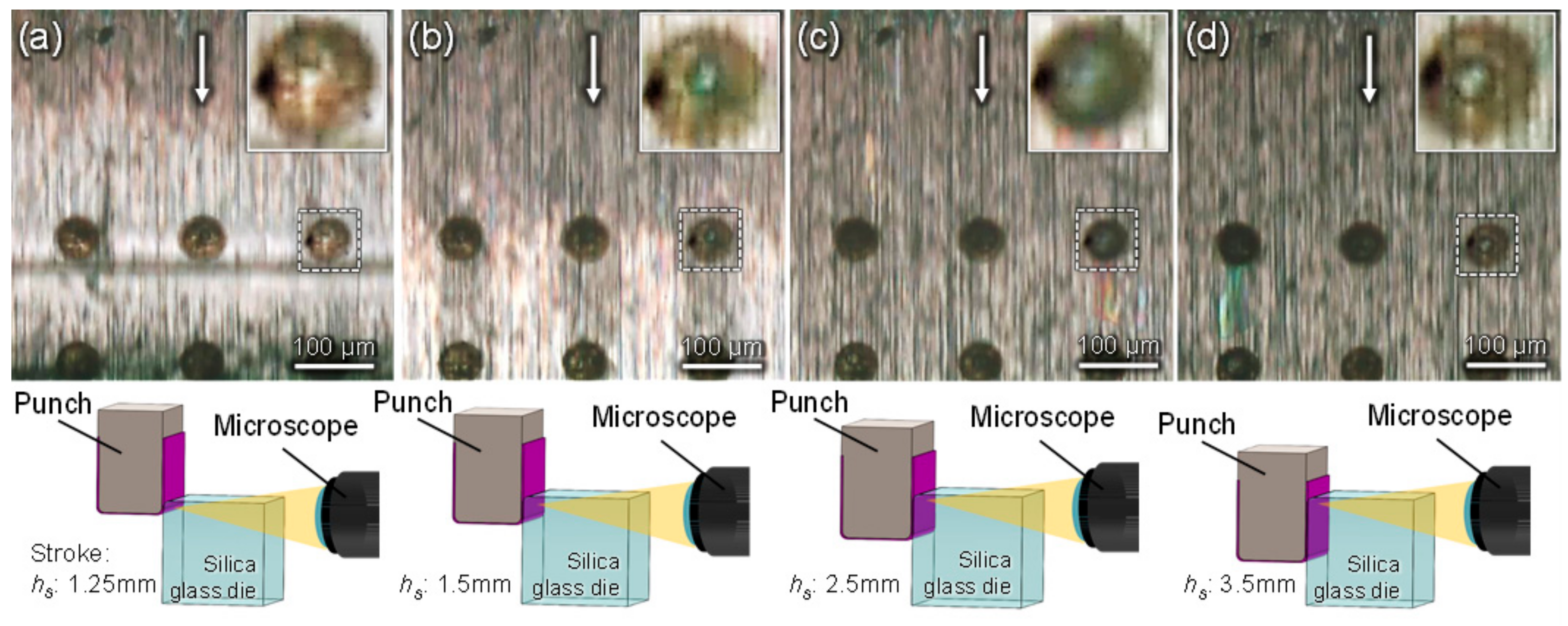
Figure 6 shows captured images from the recorded in-situ observation movies during the ironing process using a silica glass die with a dimple of 50 µm in the diameter at a stroke of (a) 1.25 mm, (b) 1.5 mm, (c) 2.5 mm and (d) 3.5 mm. The sliding direction of the work sheet is indicated by an arrow directed from top to bottom. The inset figure at each stroke shows magnified views of one dimple cell. A line below the first row of the dimples in Figure 6a indicates the edge of the radius of the work sheet bended by the punch corner radius, showing that it slides over the first row of the dimples. The area around this edge shows a stronger light reflection from the surface of the work sheet and it appears brighter. Considering from the results of the FE-analysis, the brightness of the captured images indicates the high pressure contact leading to a thin lubricant film thickness. While, the small air bubbles are generated inside the dimples directly after the radius edge of the work sheet slides over the dimples. When it slides over the second dimple row, this brighter area shifts downwards as shown in Figure 6b. The diameter of the air bubbles increases with increasing of the punch stroke. Note that brightness at the area below the first row of the dimples in the sliding direction became darker, indicating the lubricant transfer from the first to the second row. At a stroke of 2.5 mm as shown in Figure 6c, the diameter of the air bubble inside the dimples further increases. When the air bubble diameter reaches the diameter of the dimple, an area with the interference color is observed, moving from the first to the second row of the dimples along the sliding direction. Afterwards, the air bubble diameter at the first row dimples decreases as shown in the inset figure of Figure 6d indicating a refill of the lubricant inside the dimple.
A conceivable explanation for this generation of air bubbles is the air carried into the contact interface or to the local cavitation, which is caused by rapid pressure drops [25]. However, considering from the range of the relative sliding speed and the observation of the remaining air bubbles even without the movement of the punch stroke, that the cavitation effect seems to be less effective [26]. Instead, the air bubbles seem to be a flow from the surface of work material or inside of the initial lubricant. Therefore, the generation of the air bubbles and the variation of its diameter can be identified as an indicator of the lubricant supply from the dimples during the ironing process.
5.3. Effect of Micro-Dimple Diameters
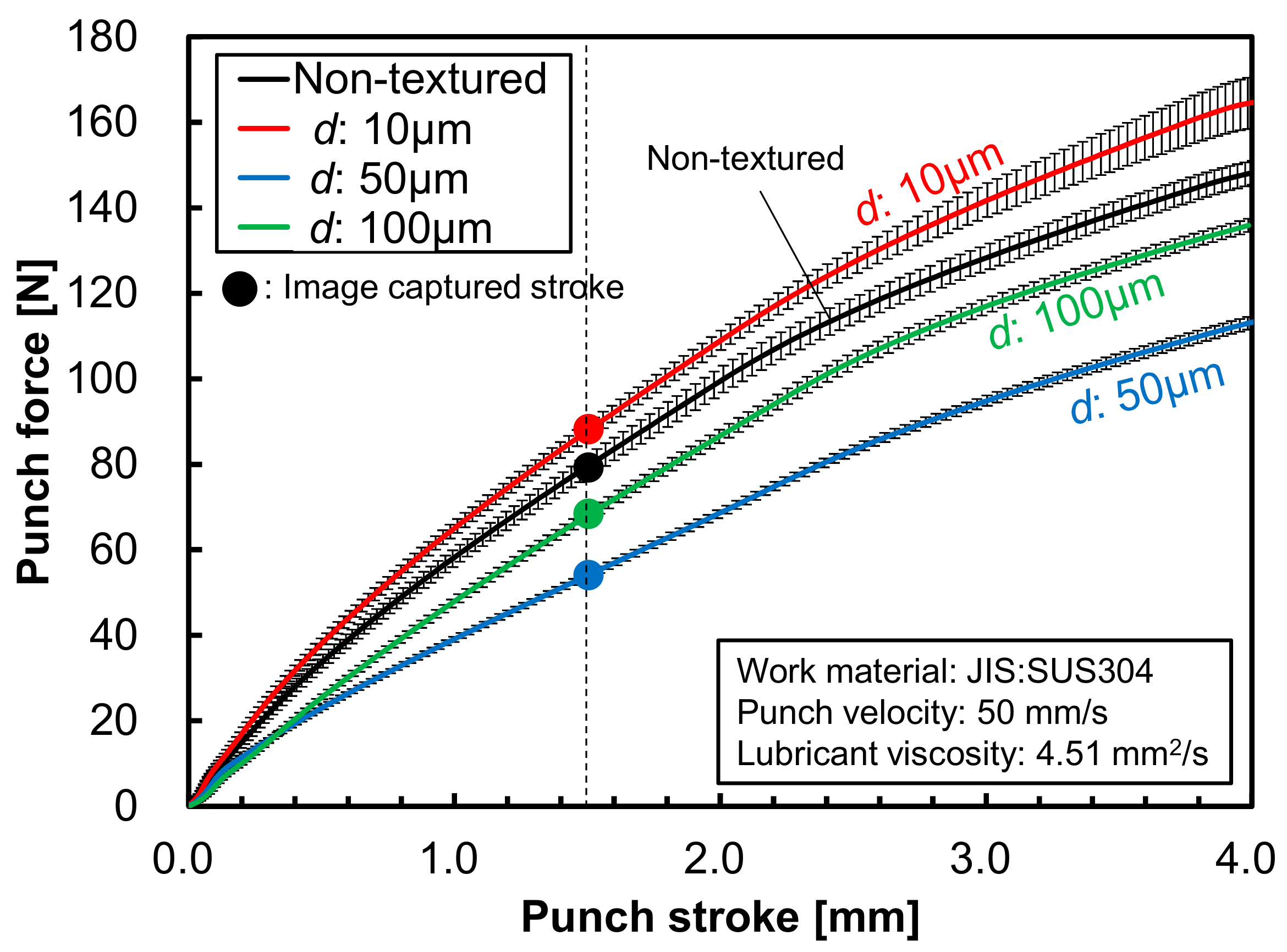
Averaged punch force–stroke curves for the non-textured die and the textured die with different dimple diameters of 10 µm, 50 µm, 100 µm are plotted in Figure 7. The error bars in the figure show the standard deviations for seven processes for each condition. In comparison with the non-textured tool surface, lower punch forces were obtained for a 50 µm and 100 µm dimple diameter, while the die with a dimple diameter of 10 µm shows higher force and it increases over seven processes.
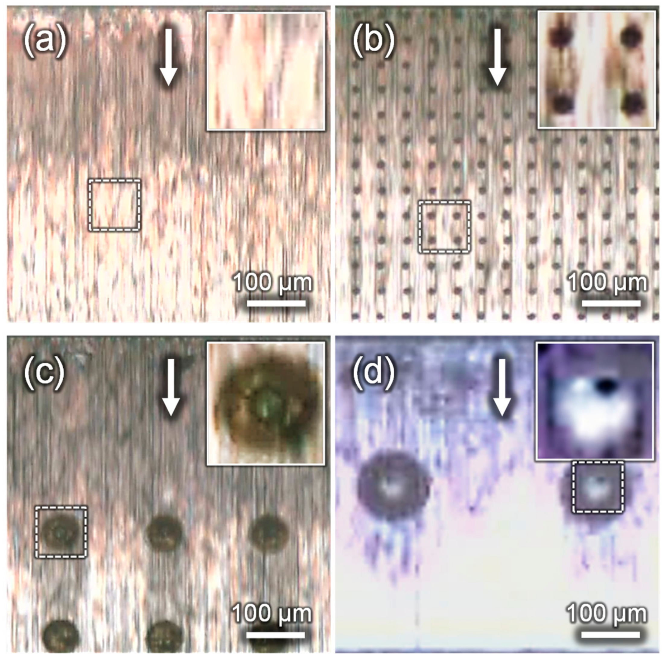
Figure 8 shows the captured images from the in-situ observation movies during the ironing process at a stroke of 1.5 mm with (a) the non-textured die and the dies with the dimple size of (b) 10 µm, (c) 50 µm and (d) 100 µm in diameter. In view of the brightness of the observation images, which shows the less lubricant under higher brightness region, the non-textured silica glass die has the brighter area at the latter half of the image, while the other textured die has the darker region below the dimple arrays. In particular, the textured dies with a dimple size of 10 µm and 50 µm in diameter show clear images of the sufficient supply of the lubricant below the dimple structure, where the lack of the lubricant was observed for the non-textured die at the same stroke of 1.5 mm. As for the textured die of 100 µm in diameter, however, the darker area between the dimples in the sliding direction do not reach the second row of dimple arrays. Additionally, the generation of the air bubbles inside the dimple structures is not clearly observed.
5.4. Effect of Lubricant Viscosity
Figure 9 shows the punch force–stroke curves of bending with the ironing processes using a 50 µm textured silica glass die with different lubricant viscosities of 1.27 mm/s2, 2.53 mm/s2 and 4.51 mm/s2. As mentioned above, error bars in the figure show the standard deviations for seven processes for each viscosity condition. The lubricant with the highest viscosity of 4.51 mm/s2 shows the lowest punch force with less deviation, while the lubricant with an intermediate viscosity of 2.53 mm/s2 indicates the slightly larger punch force. On the other hand, the lubricant with the lowest viscosity of 1.27 mm/s2 results in the highest punch force with a large deviation, which is caused by the significant increase over the series of seven processes.
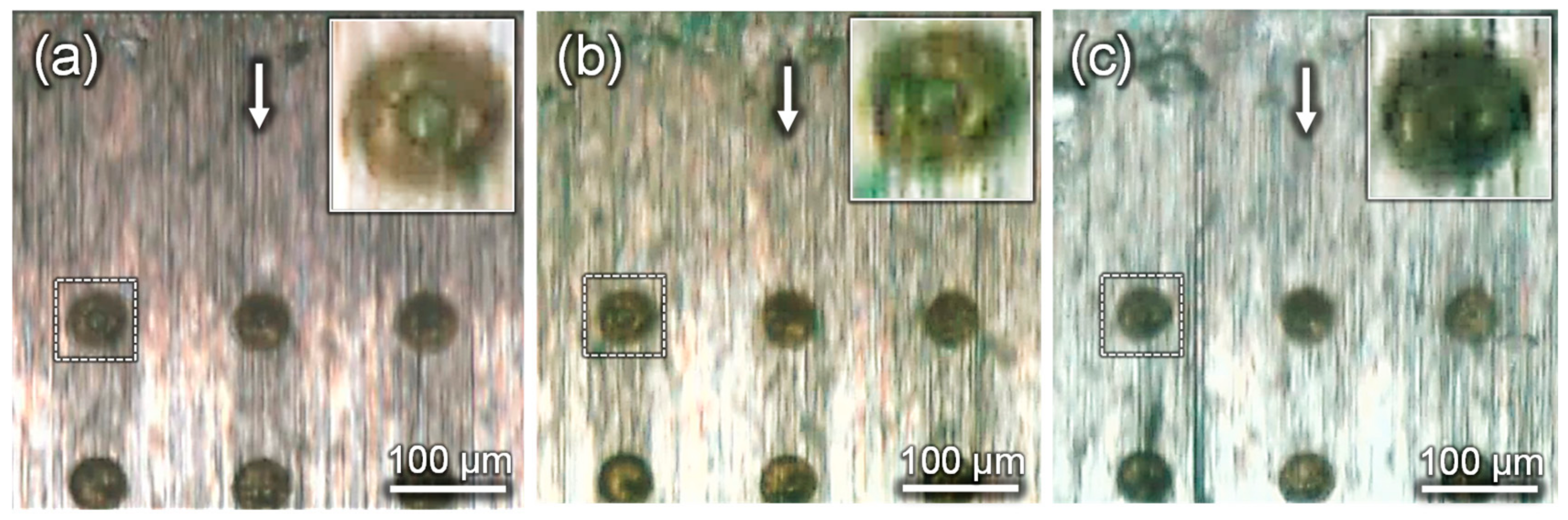
Figure 10 shows the comparison of the captured images at a 1.5 mm punch stroke with the viscosities of (a) 4.51 mm/s2, (b) 2.53 mm/s2, and (c) 1.27 mm2/s, using the silica glass die with dimple diameters of 50 µm. Since the brightness between the first and second row of the dimples were dark for the viscosity of 4.51 mm/s2 and 2.53 mm2/s, the lubricant seems to be well transferred between the dimples. On the other hand, for the lowest viscosity of 1.27 mm/s2, the brightness at the area between the first and the second row dimple arrays becomes slightly brighter, suggesting a less supply of lubricant between the dimples.
From the above observations, the sufficient lubricant supply and its transfer between the dimple arrays appear to be dominant for the difference in punch forces, as described in Section 5.3 and Section 5.4. The cause of this difference in the punch force and related lubricant flow between the different dimple dimensions are further discussed based on the results of the CFD analysis in the following sections.
6. Discussion
From the observation of the lubricant flow behavior shown in Figure 6a–d, dimple array patterns seem to act as lubricant reservoirs transferring the lubricant at the interface, which leads to a fluid film lubrication from boundary lubrication. To analyze the difference in the flow-in behavior between different dimple sizes, as shown in Figure 8, the laminar two-phase flow analysis was performed. Figure 11 shows the lubricant inflow behavior at each time step of the calculations for different dimple diameters of 10 µm, 50 µm and 100 µm. The colored side bar shows the level set value, which means the transition degree of the two phases of the lubricant and air; one for the lubricant phase and zero means the air phase. As can be seen from the transition at each time step, the time delay flowing into the dimple structure is more significant for the larger dimple size. Although the smallest dimple with 10 µm was filled with the lubricant at a step time of 0.66, the one with 100 µm was not filled with the lubricant even at a step time of 1.0. This is apparently due to the relative volume of the lubricant that flowed into the dimple to the volume of dimple structure. When we assume that the same amount of the lubricant will flow into the interface, the relative volume of the lubricant reserved into the dimple cells and the original volume of the dimple structure with different diameters can be roughly estimated by geometrical calculations.
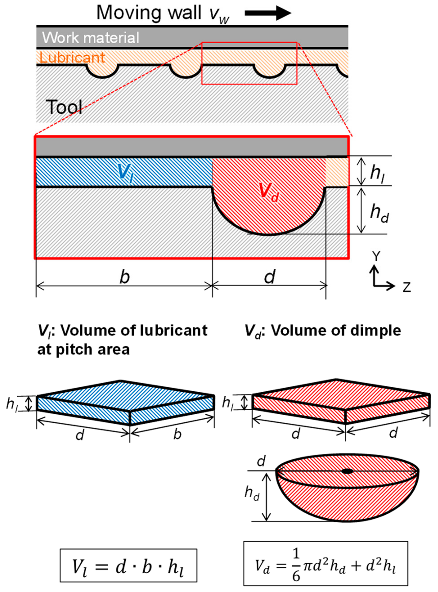
Figure 12 shows a schematic illustration of the calculation area of the lubricant volume. The geometry of the dimple cell was defined as half of the ellipsoid, and expressed as the following equation,
where Vd denotes the volume at the area of dimples and Vl is the volume of the lubricant at the area of the pitch between the dimples flowing into the dimples. According to a report of Azushima et al., the range of the thickness of lubricant films, hl, was assumed as 0.5 µm to 2.0 µm [27].
Figure 13 shows the variations of the relative volume, Vl/Vd, as a function of the lubricant film thickness. Dotted lines in the figure are quadratic approximation lines for the calculated data plots for each dimple diameter. Since the amount of lubricant flowing into the dimple structure decreases with decreasing of the lubricant film thickness, Vl/Vd indicates the decreasing tendency. In particular, the dimple size with a 100 µm in diameter shows the lowest Vl/Vd under all lubricant film thickness conditions, due to its relative large volume of the dimple cell structure compared to the amount of lubricant flow into the structure. Thus, the lubricant will not be sufficiently reserved during sliding and it will be rather difficult to be supplied to the next row of dimple arrays along the sliding direction. Those tendencies are well corresponding to the in-situ observation results, which showed the less lubricant supply between the dimple array for the 100 µm dimple size as shown in Figure 8d. In view of the inflow and retention behavior of the lubricant into the dimple structure, the relative volume of the inflow lubricant to the dimple structure is of great importance to have a sufficient retention of lubricant and its supply to the next row of the dimple arrays. Therefore, the volume of the dimple structure needs to be designed corresponding to the amount of lubricant transferred by the sliding of work materials, which is related to the lubricant viscosity, contact pressure and sliding velocity at the interface.
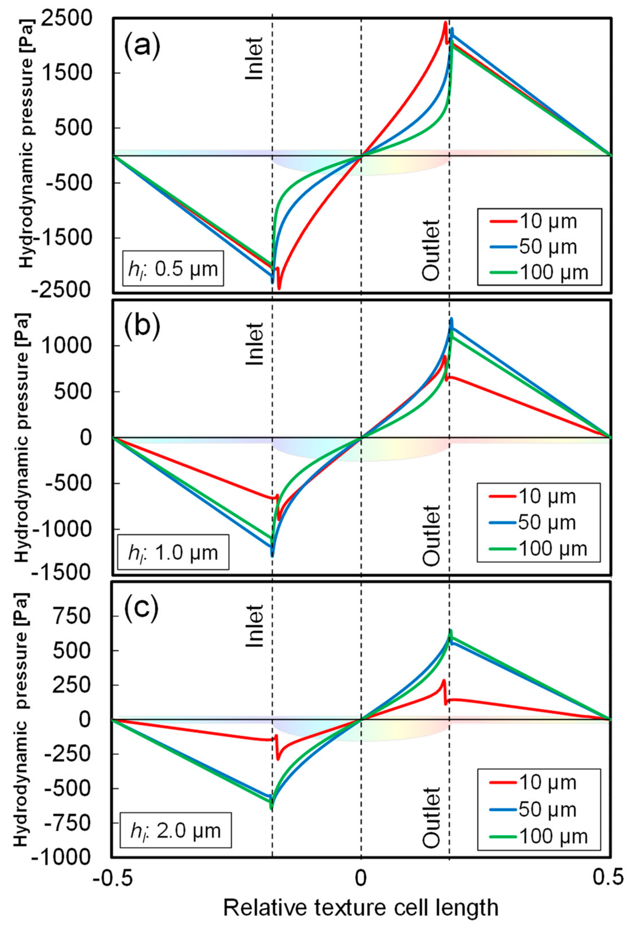
Another observation is the results of the dimple with a 10µm in diameter, which shows the highest punch forces even under the sufficient supply of lubricant between the dimple arrays as seen in Figure 8c. To further discuss the cause of this tendency, a steady state fluid flow analysis was carried out focusing on the effect of the hydrodynamic pressure. Figure 14 shows the comparison of the hydrodynamic pressure distribution between different dimple dimensions under different lubricant film thicknesses of (a) 0.5 µm, (b) 1.0 µm and (c) 2.0 µm. As a general tendency, the hydrodynamic pressure significantly decreases at the inlet of the dimple structure, and it increases at the outlet for all dimple diameters. It is well known that those significant decrease and increase of the hydrodynamic pressure at the edge of the dimples contribute to the inlet suction effect to introduce the lubricant into the dimple structure [28]. However, it can be seen that those tendencies of pressure drop and rise at the dimple cell are relatively small for the dimple with 10 µm at a film thickness of 1 µm and 2 µm. This is due to the relative small depth of the dimple cell structure compared to the lubricant film thickness. Figure 15 shows the distribution of the flow velocity and its flow lines for each dimple size of 10 µm, 50 µm and 100 µm under a lubricant film thickness of 2 µm. As can be seen from the direction of the flow lines, the vortex-like flow behavior was observed inside the dimple structure with 50 µm and 100 µm in diameter, while the coquette flow oriented to the sliding direction was obtained for that with 10 µm. The generation of the vortex flow inside the dimple might be attributed to this pressure drops, and it can be also related to the generation of the air bubbles as seen in the in-situ observations [29].
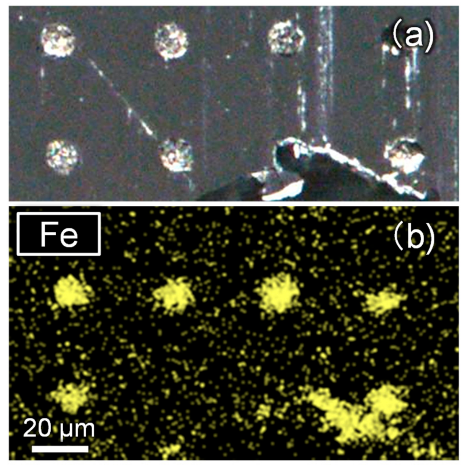
Due to this lower hydrodynamic pressure for the dimple diameter of 10 µm, the sliding contact pair can be directly contacted with each other. In fact, from the observation by using the optical microscopy as shown in Figure 16, it was found that a metallic material was accumulated inside the dimples, on which the work sheet edges slid over. This accumulation was found to wear the debris from the work material, by detecting the iron (Fe) elements from the energy dispersive X-ray (EDX) analysis as shown in Figure 16. This accumulation of wear debris may cause the instability and higher load during the ironing process.
From the viewpoint of load carrying capacity of inside the dimples, the hydrodynamic pressure drops at the inlet and rapid increase at the outlet should be taken into account, which strongly relates to the relative depth of the dimple structure to the thickness of the lubricant. Even the texture has the lubricant reservoir effect as seen in the dimple with a 10 µm in diameter, it may cause the direct contact with work materials due to the less hydrodynamic pressure, and it promotes the wear debris generation to worsen the friction properties. The similar tendency was also observed in comparison between the different viscosities of the lubricant as shown in Figure 10. The highest punch force with a large deviation at low viscosity lubricant seems to be attributed to the less hydrodynamic pressure, resulting in the flow out of the lubricant from the contact interface. Therefore, the lubricant transfer to the next dimple array patterns became difficult, as leading the direct contact with the work materials.
7. Conclusions
In the present study, to investigate the underlying mechanism of the effect of surface texturing on the lubricated sliding friction in the metal forming operation, an in-situ observation system which enables to observe the contact interface between tools and work materials during the sheet metal forming process was newly developed. The in-situ observation results under the different texture dimensions and the different lubricant viscosities are compared with the load stroke measurements and additional CFD analysis for the single cell of dimple texture. From these experimental and analytical results, the following conclusions can be drawn;
A series of inflow, retaining and supply of the lubricant at the contact interface was successfully observed during bending with the ironing process, by referring the brightness of the captured images and the generation and growth of the air bubbles inside the dimple structure as an indicator.
In comparison between the laser textured dies with different dimple diameters, the lowest punch force was obtained for the dimple diameter of 50 µm, which can be proper dimensions for the sliding contact state with a maximum pressure of 1.6 GPa at a contact length of 0.1 mm.
Although the dimple with a diameter of 100 µm also indicated the lower punch force than the non-textured die, less transfer of lubricant between dimple array patterns due to the large volume of dimple structure resulted in the higher punch force than that with 50 µm.
While for the dimple with a diameter of 10 µm, less hydrodynamic pressure due to the relative shallow depth of the structure caused the direct contact with work materials, and it resulted in the highest punch force with larger deviations.
The tendency between the different lubricant viscosities also supported the above observation that the lowest viscosity lubricant showed less lubricant transfer under low hydrodynamic pressure than the other higher viscosity lubricants.
Consequently, to obtain the sufficient load carrying capacity of the lubricant during the metal forming operation by applying the surface texturing, the contribution by the lubricant reservoir effect will be a main dominant role. To have the sufficient lubricant supply, the surface texture should be designed based on the relative volume of the dimple structure for the lubricant retention, thickness of lubricant films and the amount of lubricant transferred by the work materials during the operation. Further investigation is required to correlate those dimensional parameters of the surface texture and pitch of patterning with the distribution of the contact pressure, thickness of the lubricant film, and resulting friction properties during the forming operation.
Author Contributions
T.S. and M.Y. made the experimental concept and design, J.V. carried out the experiments, H.K. executed the FE simulation.
Funding
This work has been funded by the Tokyo Metropolitan University Co-Tutorial Program between Bremer Institute für Angewandte Strahtechnik (BIAS) and Graduate School of System Design, Tokyo Metropolitan University.
Acknowledgments
The authors gratefully acknowledge Frank Volletsen, Lukas Heinrich and Hendrik Flosky and Hamza Messaoudi at BIAS for the fruitful discussion regarding the lubricant flow behavior on dimple surface texturing. We would also like to thank Tomomi Shiratori and Yasuaki Ohsawa at Komatsu-Seiki Kosakusho. Co., Ltd. and Yoshihiro Sagisaka in Industrial Research Institute of Shizuoka Prefecture for the fabrication of surface dimple textures on silica glass die, and the Nihon-Kousakuyu Company for their support in providing lubricant with different viscosities.
Conflicts of Interest
The authors declare no conflicts of interest.
Nomenclature
| List of symbols | ||
| b | Pitch | [mm] |
| c | Clearance between punch and die | [mm] |
| d | Dimple diameter | [mm] |
| dp | Punch with | [mm] |
| E | Elastic modulus | [GPa] |
| hd | Dimple depth | [mm] |
| hl | Lubricant film thickness | [μm] |
| hs | Maximum stroke | [mm] |
| lc | Contact length | [mm] |
| np | Number of forming processes | (dimensionless) |
| pc | Contact pressure | [MPa] |
| rd | Bending die radius | [mm] |
| rp | Punch radius | [mm] |
| t | Work sheet thickness | [mm] |
| T | Temperature | [˚C] |
| u | Kinematic viscosity | [mm2/s] |
| vp | Punch velocity | [mm/s] |
| vw | Sliding wall velocity | [mm/s] |
| vf | Flow velocity | [mm/s] |
| Vd | Volume of dimple cell | [mm3] |
| Vl | Volume of lubricant at pitch area | [mm3] |
| w | Width of die gap | [mm] |
| Greek letters | ||
| µ | Friction coefficient | (dimensionless) |
| η | Kinematic viscosity of lubricant | [mm2/s] |
| ηlub | Lubricant viscosity | [Pa·s] |
| ηgas | Gas viscosity | [Pa·s] |
| λ | Dimple aspect ratio | (dimensionless) |
| ρ | Mass density of fluid | [kg/m3] |
| ρgas | Gas density | [kg/m3] |
| ρliquid | Liquid density | [kg/m3] |
| ρd | Texture density ratio | (dimensionless) |
| σ | Surface tension coefficient | [mN/m] |
| σy | Yield stress | [MPa] |
| ν | Poisson’s ratio | (dimensionless) |
| θ | Contact angle | [degree] |
| φ | Level set function | (dimensionless) |
References
- Wagner, K.; Volkl, R.; Engel, U. Tool life enhancement in cold forging by locally optimized surfaces. J. Mater. Process. Technol. 2008, 201, 2–8. [Google Scholar] [CrossRef]
- Steinhof, K.; Rasp, W.; Pawelski, O. Development of deterministic-stochastic surface structures to improve the tribological conditions of sheet forming processes. J. Mater. Process. Technol. 1996, 60, 355–361. [Google Scholar] [CrossRef]
- Zhou, R.; Cao, J.; Wang, Q.J.; Meng, F.; Zimowski, K.; Xia, Z.C. Effect of EDT surface texturing on tribological behavior of aluminum sheet. J. Mater. Process. Technol. 2011, 211, 1643–1649. [Google Scholar] [CrossRef]
- Evans, C.J.; Bryan, J.B. “Structured”, “Textured”, or “Engineered” Surfaces. CIRP Ann. 1999, 48, 541–556. [Google Scholar] [CrossRef]
- Geiger, M.; Popp, U.; Engel, U. Excimer laser micro texturing of cold forging tool surfaces-influence on tool life. CIRP Ann. 2002, 51, 231–234. [Google Scholar] [CrossRef]
- Costa, H.L.; Hutchings, I.M. Effects of die surface patterning on lubrication in strip drawing. J. Mater. Process. Technol. 2009, 209, 1175–1180. [Google Scholar] [CrossRef]
- Xu, D.; Wu, W.; Malhotra, R.; Chen, J.; Lu, B.; Cao, J. Mechanism investigation for the influence of tool rotation and laser surface texturing (LST) on formability in single point incremental forming. Int. J. Mach. Tools Manuf. 2013, 73, 37–46. [Google Scholar] [CrossRef]
- Hamilton, D.B.; Walowit, J.A.; Allen, C.M. A theory of lubrication by micro- irregularities. J. Fluids Eng. 1966, 88, 177–185. [Google Scholar]
- Wakuda, M.; Yamauchi, Y.; Kanzaki, S.; Yasuda, Y. Effect of surface texturing on friction reduction between ceramic and steel materials under lubricated sliding contact. Wear 2003, 254, 356–363. [Google Scholar] [CrossRef]
- Varenberg, M.; Halperin, G.; Etsion, I. Different aspects of the role of wear debris in fretting wear. Wear 2002, 252, 902–910. [Google Scholar] [CrossRef]
- Ibatan, T.; Uddin, M.S.; Chowdhury, M.A.K. Recent development on surface texturing in enhancing tribological performance of bearing sliders. Surf. Coat. Technol. 2015, 272, 102–120. [Google Scholar] [CrossRef]
- Gropper, D.; Wang, L.; Harvey, T.J. Hydrodynamic lubrication of textured surfaces: A review of modeling techniques and key findings. Tribol. Int. 2016, 94, 509–529. [Google Scholar] [CrossRef] [Green Version]
- Ramesh, A.; Akram, W.; Mishra, S.P.; Cannon, A.H.; Polycarpou, A.A.; King, W.P. Friction characteristic of microtextured surface under mixed and hydrodynamic lubrication. Tribol. Int. 2013, 57, 170–176. [Google Scholar] [CrossRef]
- Profito, F.J.; Vlădescu, S.J.; Reddyhoff, T.; Dini, D. Transient experimental and modelling studies of laser-textured micro-grooved surface with a focus on piston-ring cylinder liner contacts. Tribol. Int. 2017, 113, 125–136. [Google Scholar] [CrossRef]
- Ike, H.; Makinouchi, A. Effect of lateral tension and compression on plane strain flattening processes of surface asperities lying over a plastically deformable bulk. Wear 1990, 140, 7–38. [Google Scholar] [CrossRef]
- Schey, J.A. Tribology in Metalworking. Friction, Lubrication and Wear; ASM, Metals Park: Novelty, OH, USA, 1983. [Google Scholar]
- Azushima, A.; Uda, M.; Kudo, H. An interpretation of the speed dependence of the coefficient of friction under the micro PHL condition in sheet drawing. CIRP Ann. 1991, 40–41, 227–230. [Google Scholar] [CrossRef]
- Mizuno, T.; Okamoto, M. Effects of lubricant viscosity at pressure and sliding velocity on lubricating conditions in the compression- friction test on sheet metals. Trans. ASME J. Lubr. Technol. 1982, 104, 53–59. [Google Scholar] [CrossRef]
- Bay, N.; Azushima, A.; Groche, P.; Ishibashi, I.; Merklein, M.; Morishita, M.; Nakamura, T.; Schmid, S.; Yoshida, M. Environmentally benign tribo-systems for metal forming. CIRP Ann. 2010, 59, 760–780. [Google Scholar] [CrossRef] [Green Version]
- Gachot, C.; Rosenkarnz, A.; Hsu, S.M.; Costa, H.L. A critical assessment of surface texturing for friction and wear improvement. Wear 2017, 372–373, 21–41. [Google Scholar] [CrossRef]
- Shin-etsu Quartz, Co. Available online: https://www.sqp.co.jp/catalog/images/Technology_Guide1_j.pdf (accessed on 18 November 2017).
- Tokyo Kohshin, Co. Available online: http://tokyokohshin.co.jp/wp/wp-content/themes/theme064/images/pdf/skd11_hi.pdf (accessed on 18 November 2017).
- Sethian, J.A.; Smereka, P. Level set methods for fluid interface. Ann. Rev. Fluid Mech. 2003, 35, 341–372. [Google Scholar] [CrossRef]
- Sussman, M.; Smereka, P.; Osher, S. A level set approach for computing solutions to incompressible two-phase flow. J. Comput. Phys. 1994, 114, 146–159. [Google Scholar] [CrossRef]
- Wahl, R.; Schneider, J.; Gumbsch, P. In situ observation of cavitation in crossed microchannels. Tribol. Int. 2012, 55, 81–86. [Google Scholar] [CrossRef]
- Qiu, Y.; Khonasari, M.M. Experimental investigation of tribological performance of laser textured stainless steel rings. Tribol. Int. 2011, 44, 635–644. [Google Scholar] [CrossRef]
- Azushima, A. In lubro 3D measurement of oil film thickness at the interface between tool and workpiece in sheet drawing using a fluorescence microscope. Tribol. Int. 2005, 38, 105–112. [Google Scholar] [CrossRef]
- Olver, A.V.; Fowell, M.T.; Spikes, H.A.; Pegg, I.G. ‘Inlet suction’, a load support mechanism in non-convergent, pocketed, hydrodynamic bearings. Proc. Inst. Mech. Eng. Part J J. Eng. Tribol. 2006, 220, 105–108. [Google Scholar] [CrossRef]
- Karker, A.; Ostayen, R.A.J.; Beek, A.; Rixen, D.J. A multiscale method modeling surface texture effects. J. Tribol. 2007, 129, 221–230. [Google Scholar] [CrossRef]
Figure 1.
Schematic illustrations of the in-situ observation system, (a) bending with ironing die assembly, (b) appearance of the system and (c) dimensions of bending with ironing dies and punch.
Figure 1.
Schematic illustrations of the in-situ observation system, (a) bending with ironing die assembly, (b) appearance of the system and (c) dimensions of bending with ironing dies and punch.

Figure 2.
Confocal laser scanning microscope images of the laser textured dimple cell with a diameter of (a) 10 μm, (b) 50 μm, (c) 100 μm and (d) its surface line profiles.
Figure 2.
Confocal laser scanning microscope images of the laser textured dimple cell with a diameter of (a) 10 μm, (b) 50 μm, (c) 100 μm and (d) its surface line profiles.

Figure 3.
Schematic illustration of the finite element (FE) model for the contact state analysis of bending with the ironing process.
Figure 3.
Schematic illustration of the finite element (FE) model for the contact state analysis of bending with the ironing process.
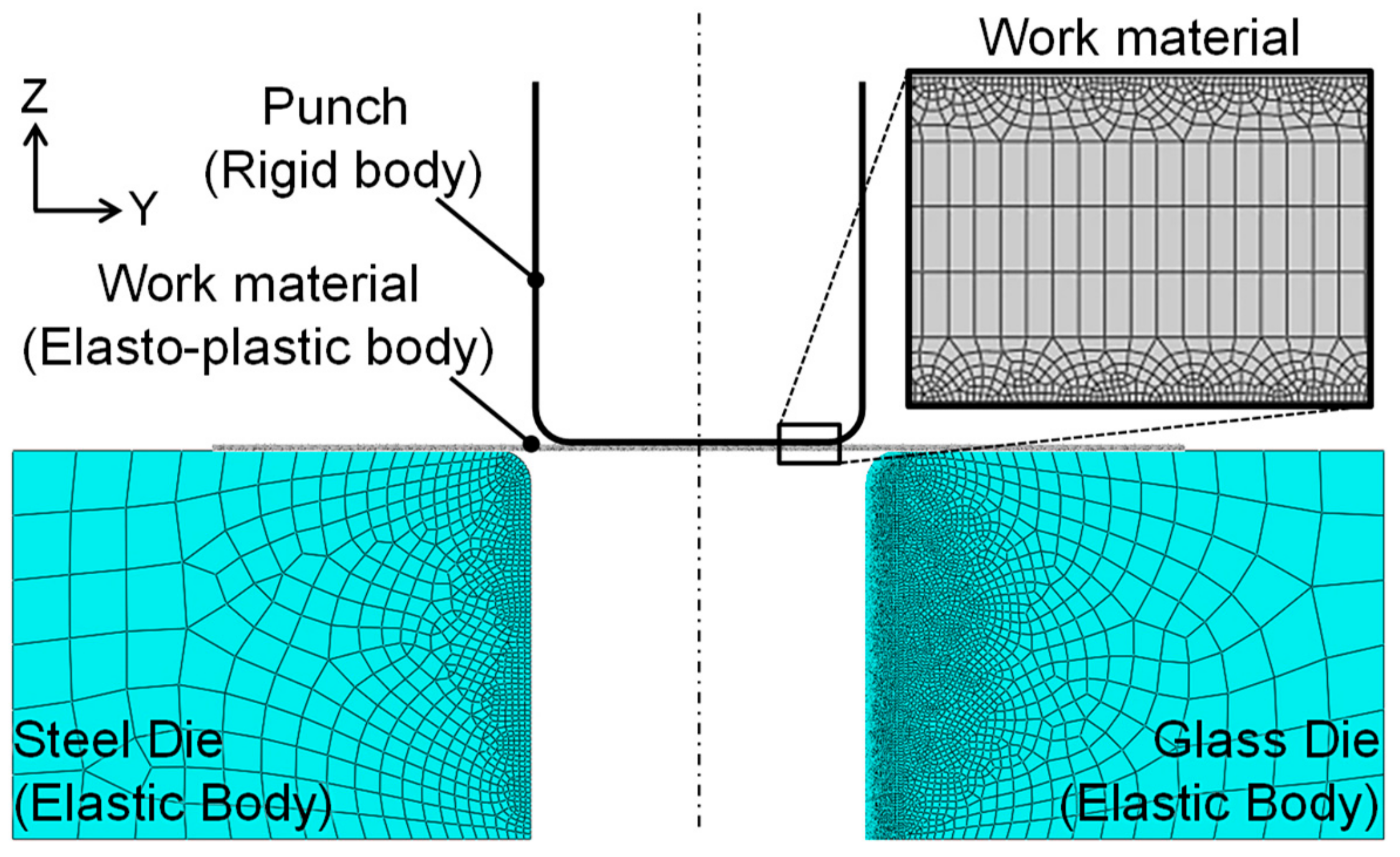
Figure 4.
Schematic illustration of the model of micro dimple cells for the CFD (computational fluid dynamics) analysis.
Figure 4.
Schematic illustration of the model of micro dimple cells for the CFD (computational fluid dynamics) analysis.
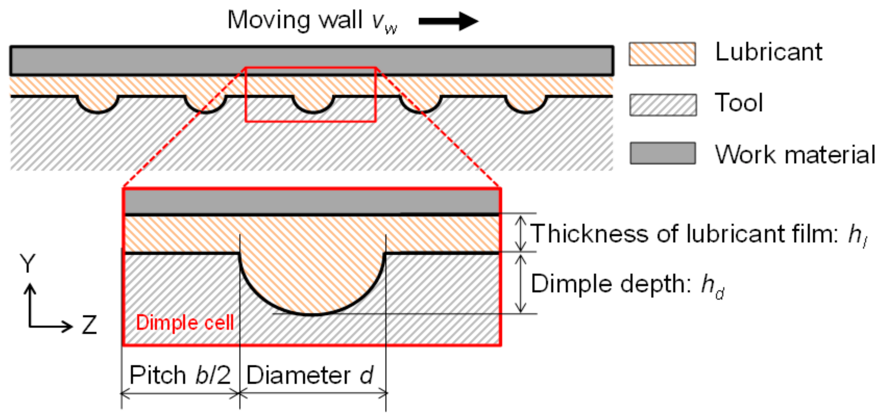
Figure 5.
Results of the contact state analysis. (a) Variations of the contact pressure and apparent contact length during bending with the ironing process, (b) variation of the equivalent stress distribution at each punch stroke denoted in (a).
Figure 5.
Results of the contact state analysis. (a) Variations of the contact pressure and apparent contact length during bending with the ironing process, (b) variation of the equivalent stress distribution at each punch stroke denoted in (a).
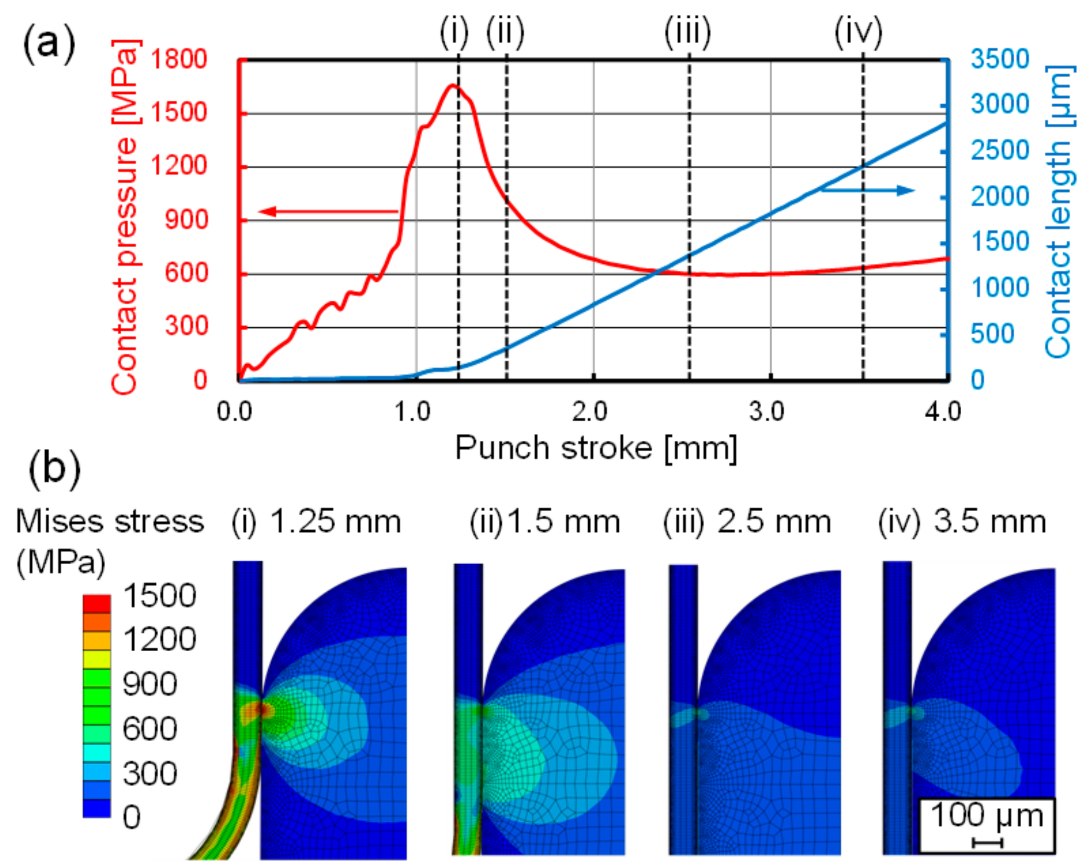
Figure 6.
Captured images from in-situ observations at various punch strokes of (a) hs:1.25 mm, (b) hs:1.5 mm, (c) hs:2.5 mm and (d) hs:3.5 mm in bending with the ironing process using the surface textured die with a dimple diameter of 50 μm.
Figure 6.
Captured images from in-situ observations at various punch strokes of (a) hs:1.25 mm, (b) hs:1.5 mm, (c) hs:2.5 mm and (d) hs:3.5 mm in bending with the ironing process using the surface textured die with a dimple diameter of 50 μm.

Figure 7.
Punch force–stroke curves of bending with the ironing process using the non-textured die and surface textured die with different dimple diameters of 10 µm, 50 µm, and 100 µm.
Figure 7.
Punch force–stroke curves of bending with the ironing process using the non-textured die and surface textured die with different dimple diameters of 10 µm, 50 µm, and 100 µm.

Figure 8.
Captured images from in-situ observations at a punch stroke of 1.5 mm in bending with the ironing process using (a) the non-textured die and surface textured die with different dimple diameters of (b) 10 μm, (c) 50 μm and (d) 100 μm.
Figure 8.
Captured images from in-situ observations at a punch stroke of 1.5 mm in bending with the ironing process using (a) the non-textured die and surface textured die with different dimple diameters of (b) 10 μm, (c) 50 μm and (d) 100 μm.

Figure 9.
Comparison of punch force–stroke curves between different lubricant viscosities in bending with the ironing process using the surface textured die with dimple diameters of 50 µm.
Figure 9.
Comparison of punch force–stroke curves between different lubricant viscosities in bending with the ironing process using the surface textured die with dimple diameters of 50 µm.
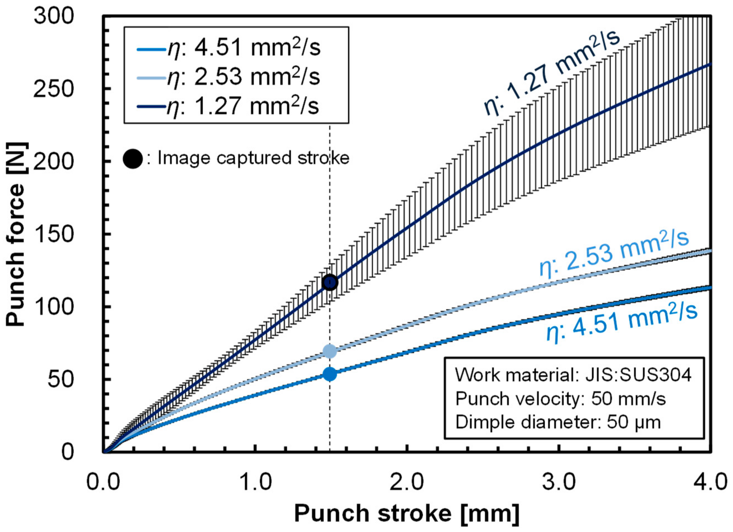
Figure 10.
Captured images from in-situ observations at a punch stroke of 1.5 mm in bending with the ironing process with a 50 μm-dimple textured die using lubricants with different viscosities of (a) 4.51 mm/s2, (b) 2.53 mm/s2, and (c) 1.27 mm2/s.
Figure 10.
Captured images from in-situ observations at a punch stroke of 1.5 mm in bending with the ironing process with a 50 μm-dimple textured die using lubricants with different viscosities of (a) 4.51 mm/s2, (b) 2.53 mm/s2, and (c) 1.27 mm2/s.

Figure 11.
Comparison of the variations of the flow-in behavior of the lubricant at different time steps in the laminar two-phase flow analysis for different dimple diameters of 10 µm, 50 µm and 100 µm.
Figure 11.
Comparison of the variations of the flow-in behavior of the lubricant at different time steps in the laminar two-phase flow analysis for different dimple diameters of 10 µm, 50 µm and 100 µm.
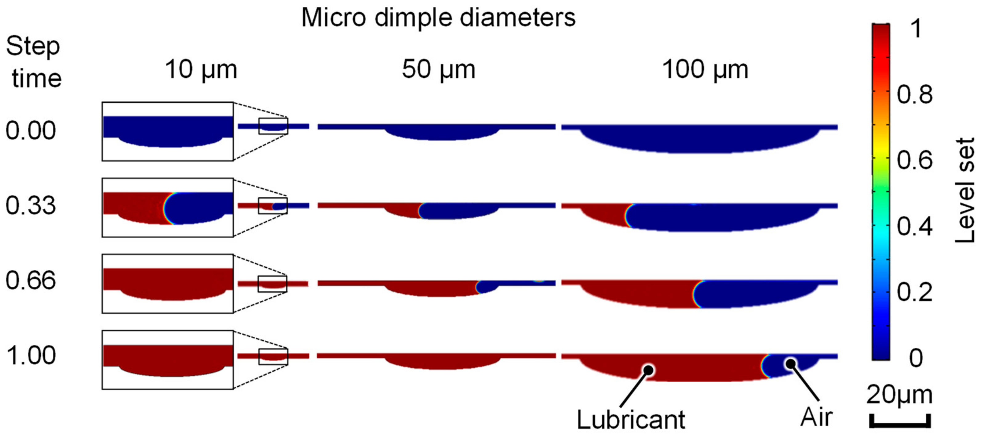
Figure 12.
Schematic illustration for geometrical calculations of the relative volume of lubricant flow into the dimple cell Vl and the volume of dimple cell structure Vd.
Figure 12.
Schematic illustration for geometrical calculations of the relative volume of lubricant flow into the dimple cell Vl and the volume of dimple cell structure Vd.

Figure 13.
Variations of the relative volume Vl/Vd as a function of the lubricant film thickness hl for different dimple diameters of 10 µm, 50 µm, and 100 µm. Dotted lines are quadratic approximated lines for the data of each dimple diameter.
Figure 13.
Variations of the relative volume Vl/Vd as a function of the lubricant film thickness hl for different dimple diameters of 10 µm, 50 µm, and 100 µm. Dotted lines are quadratic approximated lines for the data of each dimple diameter.
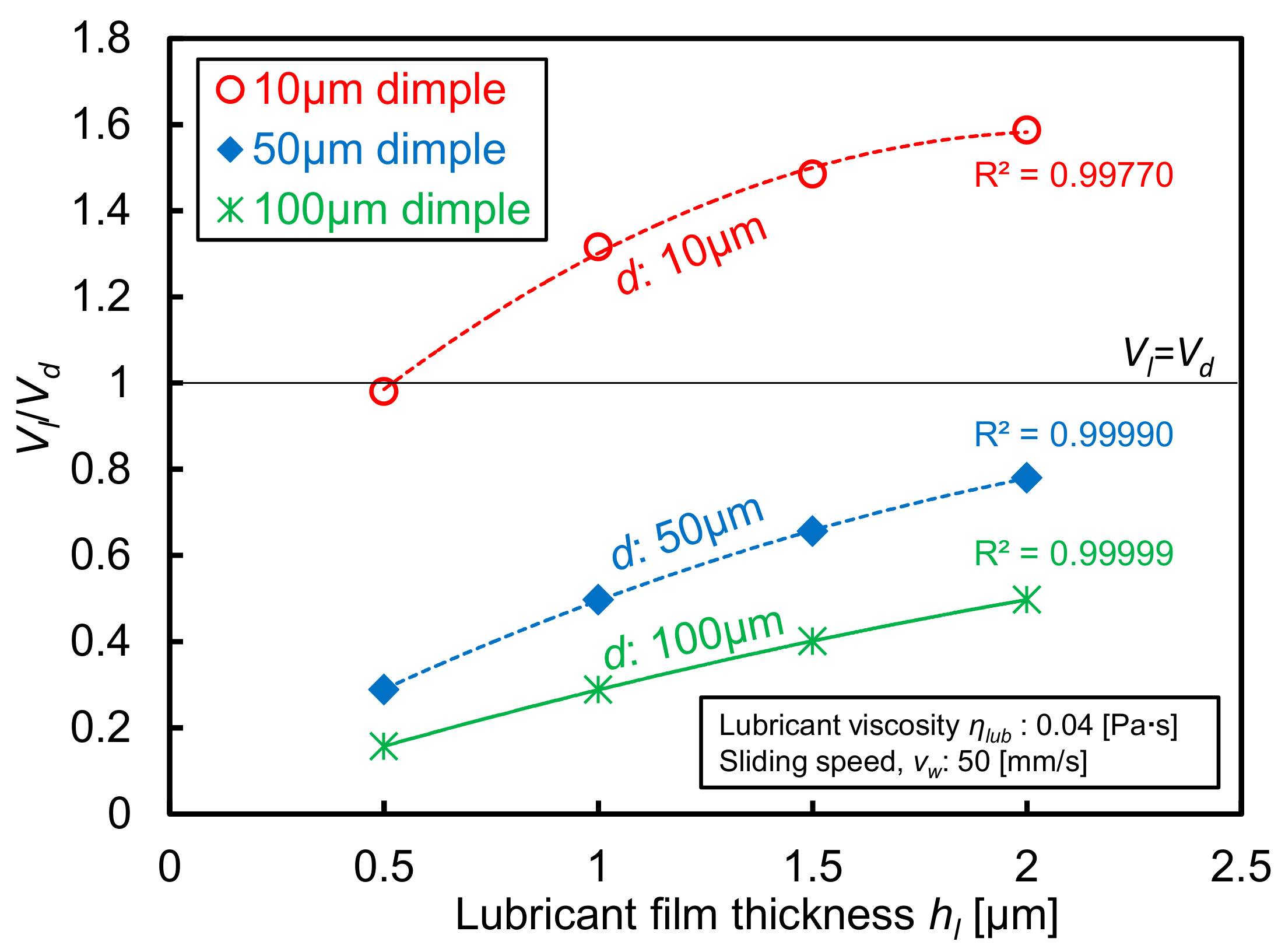
Figure 14.
Comparisons of the calculated hydrodynamic pressure distribution between different dimple diameters of 10 µm, 50 µm and 100 µm under different lubricant film thicknesses hl of (a) 0.5 µm, (b) 1.0 µm and (c) 2.0 µm.
Figure 14.
Comparisons of the calculated hydrodynamic pressure distribution between different dimple diameters of 10 µm, 50 µm and 100 µm under different lubricant film thicknesses hl of (a) 0.5 µm, (b) 1.0 µm and (c) 2.0 µm.

Figure 15.
Comparison of the distribution of the lubricant flow velocity in the dimple cells with different diameters of 10 µm, 50 µm, 100 µm under a lubricant film thickness of 2.0 µm.
Figure 15.
Comparison of the distribution of the lubricant flow velocity in the dimple cells with different diameters of 10 µm, 50 µm, 100 µm under a lubricant film thickness of 2.0 µm.
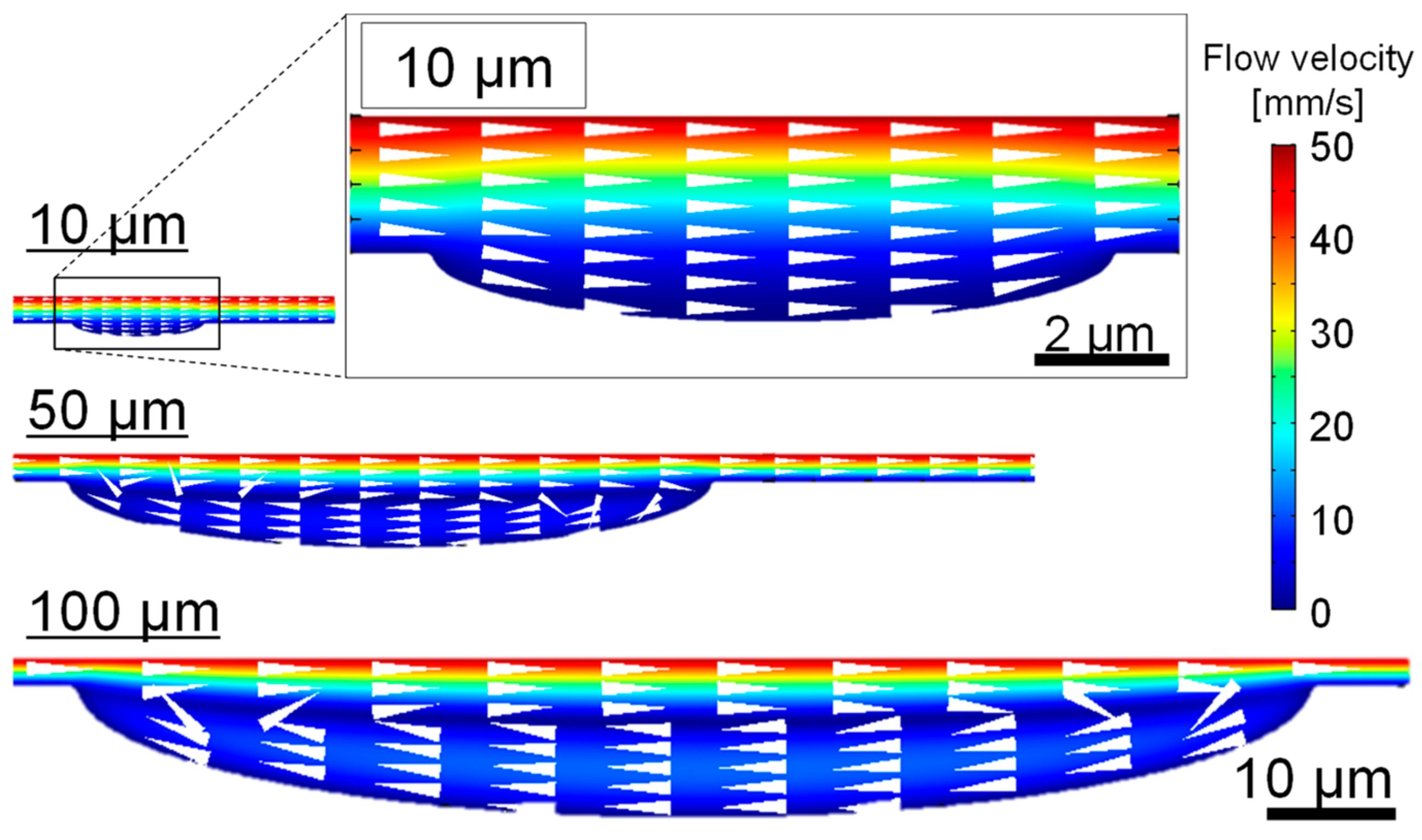
Figure 16.
Surface images of silica glass die with textured dimple with 10 µm in diameter after bending with ironing processes, (a) optical microscopic image, (b) EDX (energy dispersive X-ray) mapping of Fe (Iron).
Figure 16.
Surface images of silica glass die with textured dimple with 10 µm in diameter after bending with ironing processes, (a) optical microscopic image, (b) EDX (energy dispersive X-ray) mapping of Fe (Iron).

Table 1.
Geometrical parameters of micro dimple arrays.
| Texture Density ρd | Aspect Ratio λ | Diameter d [mm] | Depth hd [mm] | Pitch b [mm] |
|---|---|---|---|---|
| 0.1 | 0.1 | 0.1 | 0.01 | 0.18 |
| 0.1 | 0.1 | 0.05 | 0.005 | 0.09 |
| 0.1 | 0.1 | 0.01 | 0.001 | 0.02 |
Table 2.
Operation conditions of bending with the ironing process.
| Work Material | Stainless Steel | (JIS:SUS304-H) |
|---|---|---|
| Sheet thickness t | [mm] | 0.1 |
| Bending die radius rd | [mm] | 0.5 |
| Punch corner radius rp | [mm] | 0.5 |
| Clearance c | [mm] | 0.09 |
| Maximum stroke hs | [mm] | 4 |
| Punch Velocity vp | [mm/s] | 50 |
| Lubricant viscosity η | [mm2/s] | 1.27, 2.53, 4.51 |
Table 3.
Analytical conditions of material models for the contact state analysis.
| Material | Stainless Steel | Silica Glass Die | Tool Steel Die | (JIS:SUS304-H) |
|---|---|---|---|---|
| Material model | Elasto-plastic body | Elastic body | Elastic body | |
| Mass density ρ | [g/cm3] | 7.93 | 2.2 | 7.72 |
| Elastic modulus E | [GPa] | 200 | 72 | 206 |
| Yield stress σy | [MPa] | 1170 | - | - |
| Poisson’s ratio ν | 0.3 | 0.17 | 0.3 |
Table 4.
Analytical conditions for the laminar two-phase flow analysis.
| Mass Density of Lubricant ρliquid | [kg/m3] | 899.8 |
| Lubricant viscosity of ηlub | [Pa·s] | 0.04 |
| Sliding speed vw | [mm/s] | 50 |
| Flow velocity vf | [mm/s] | 50 |
| Lubricant film thickness hl | [µm] | 2 |
| Density of gas ρgas | [kg/m3] | 1.2 |
| Viscosity of gas ηgas | [Pa·s] | 1.8 × 10⁻⁵ |
| Atmosphere temperature T | [K] | 293.15 |
| Contact angle θ | [degrees] | 20 |
Table 5.
Analytical conditions for the fluid-flow analysis.
| Mass Density ρ | [kg/m3] | 899.8 |
| Viscosity ηl | [Pa·s] | 0.04 |
| Sliding speed vw | [mm/s] | 50 |
| Lubricant film thickness hl | [µm] | 0.5, 1, 2 |
© 2019 by the authors. Licensee MDPI, Basel, Switzerland. This article is an open access article distributed under the terms and conditions of the Creative Commons Attribution (CC BY) license (http://creativecommons.org/licenses/by/4.0/).
Share and Cite
MDPI and ACS Style
Shimizu, T.; Kobayashi, H.; Vorholt, J.; Yang, M. Lubrication Analysis of Micro-Dimple Textured Die Surface by Direct Observation of Contact Interface in Sheet Metal Forming. Metals 2019, 9, 917. https://doi.org/10.3390/met9090917
AMA Style
Shimizu T, Kobayashi H, Vorholt J, Yang M. Lubrication Analysis of Micro-Dimple Textured Die Surface by Direct Observation of Contact Interface in Sheet Metal Forming. Metals. 2019; 9(9):917. https://doi.org/10.3390/met9090917
Chicago/Turabian StyleShimizu, Tetsuhide, Hiroyuki Kobayashi, Jochen Vorholt, and Ming Yang. 2019. "Lubrication Analysis of Micro-Dimple Textured Die Surface by Direct Observation of Contact Interface in Sheet Metal Forming" Metals 9, no. 9: 917. https://doi.org/10.3390/met9090917
Note that from the first issue of 2016, this journal uses article numbers instead of page numbers. See further details here.