Article

Influence of Tool Material, Tool Geometry, Process Parameters, Stacking Sequence, and Heat Sink on Producing Sound Al/Cu Lap Joints through Friction Stir Welding

1
College of Mechanical & Electrical Engineering, Nanjing University of Aeronautics & Astronautics, Nanjing 210016, China
2
Faculty of Mechanical Engineering, GIK Institute of Engineering Sciences & Technology, Topi 23460, Pakistan
3
Mechanical Engineering Department, Universiti Teknologi Petronas, Bandar Seri Iskandar, Perak 32610, Malaysia
*
Author to whom correspondence should be addressed.
Metals 2019, 9(8), 875; https://doi.org/10.3390/met9080875
Submission received: 28 June 2019 / Revised: 22 July 2019 / Accepted: 23 July 2019 / Published: 8 August 2019
(This article belongs to the Special Issue Advanced Welding Technology in Metals)

Abstract

:
The present study was focused on establishing guidelines for successful friction stir welding of Al alloys and Cu lap joints. Detailed investigations in respect to tool geometry, tool material, work-piece material, welding parameters, stacking sequence, and heat sink were carried out. The soundness of welded joints was tested through microscopic analysis and the lap shear test. The results revealed that the tungsten carbide (WC) tool with square-pin produced sound joints in terms of minimized defects and high strength. Further, the use of heat sink proved as an important pre-requisite when the stacking sequence was inversed (i.e., Cu-Al), and this stacking configuration in comparison with the Al-Cu stacking yielded weaker joints. The influence of the tool welding speed (F, mm/min) was found to depend upon the tool material. A range of tool welding speed (23.5–37.5 mm/min) worked well for the WC tool. However, only two values of welding speed (30 mm/min and 37 mm/min) were observed to be conducive when the tool material was HSCo (high-speed cobalt)-steel. Finally, it was concluded to employ the WC tool with square-pin, a welding speed of 30 mm/min, the rotational speed (S, rpm) of 1500 mm/min, and Al-Cu stacking sequence to successfully process the Al/Cu lap joints.

1. Introduction

Al-Cu bilayer sheet offers an attractive combination of high thermal and electrical conductivity and good corrosion resistance. This combination of metals is also comparatively cheaper than the standalone Cu sheet. Owing to these salient properties, the Al-Cu metal has found a host of applications in aerospace, chemical, transport, electronic, and power industries [1]. The most common applications include electrical connectors, power supply module, power LED, heat sinks, electromagnetic shielding, solder float, and radiators. Another interesting application of Al-Cu sheet is that it can be employed as a fire-resistant material [2]. Numerous conventional joining techniques such as brazing and laser welding are applied to join Al and Cu but it is challenging because of the difference in the physical and chemical properties of the metals and the tendency to form brittle intermetallic compounds (IMCs) during the formation of welded joints [3]. These IMCs can impair the mechanical and electrical properties of the joint [4].
The temperature of metals in solid-state joining, on the other hand, does not approach melting point and this fact minimizes the undesired formation of intermetallics in dissimilar joints. Friction stir welding (FSW) is relatively an innovative solid-state welding technique, whereby joining is realized by the stirring action of a pin-tool without applying any significant external heating. This aspect renders FSW a very competitive process for joining the dissimilar metals, as described in the literature [5,6,7,8]. Besides experimental analyses, numerical modeling has also significant contribution in establishing the fundamentals of FSW process. Luo et al. [9] worked on numerical modeling of AA2A14-T6 to visualize the material flow during the FSW process. They found that either high welding speed or low rotational speed could cause welding defects such as holes and cracks. Dialami et al. [10] performed numerical modeling to study the microstructure evolution of AZ31Mg alloy during FSW and established relation among grain size, strain rate, micro-hardness, and temperature.
Some researchers [11,12] have attempted to produce dissimilar joints of Al with other metals. Sharma et al. [13] utilized five different pin profiles including cylindrical, taper, cylindrical cam, taper cam, and square to produce butt joint between AA5754 and commercially pure Cu. They reported that square-pin offered better mechanical properties because it facilitated mixing at the nugget zone. Akbari et al. [14] examined the trend of mechanical properties with respect to the material position in dissimilar 7070 Al/Cu lap joint and showed that better welded joint quality achieved when Al was placed on the top of Cu. Bisadi et al. [15] studied the effect of FSW parameters on the microstructure and mechanical properties of Al 5083 and commercial Cu FSW lap joint and reported that very low and very high welding temperature can lead to several joint defects like channel and voids defects. Celik et al. [16] performed a similar investigation on Al/Cu butt joint and suggested that higher tensile strength is attributed to dispersion strengthening of fine Cu particles distributed over the Al material in the stir zone.
Karimi et al. [17] investigated the effect of tool material on the metallurgical and mechanical properties of dissimilar Al/Cu butt joints. They found that the tool with low thermal conductivity produced better welded joints. Çevik et al. [18] employed uncoated and TiN-coated X210Cr12 steel tools in order to fabricate 7075-T651 Al butt joints revealing that the uncoated tool produced favored results. Bozkurt et al. [19], on the other hand, observed opposite findings while butt welding of AA2124-T4 alloy with uncoated and CrN and AlTiN-coated HSS tools.
Although some scholars [14,15,20,21,22,23] have performed work on different aspects of FSW of Al/Cu lap joint, a common agreement has not yet arrived in certain respects. As an example, the effect of tool material has not been agreed upon. Furthermore, nature of the influence of various factors is associated with the type of weld (say butt or lap). Therefore, more investigations are required to acquire a thorough understanding on FSW of Al/Cu lap joints. Moreover, most studies furnish knowledge on one or two aspects of the process. A comprehensive study undertaking a range of important aspects/factors can provide useful insights to the user for successful welding. The present study is an attempt in this direction wherein the effects of a number of factors namely tool geometry, tool material, process parameters, stacking sequence, and heat sink are taken into account.
Two types of tool materials namely HSCo and WC; two thicknesses of materials (1.65 mm and 3 mm for Cu and 2.15 mm and 4 mm for Al); and two types of tool geometries namely round and square are employed. To successfully produce Al/Cu lap joints at varying of these variables, the welding speed and rotational speed are altered over a range. It is observed that the joining results (i.e., lap shear strength and defects) vary as either of the tool material, plate thickness, or tool geometry is changed. Further, the favorable range of feed and speed also experiences a change with a change in the rest of the conditions. The presented results can serve as a guideline to produce sound FSW Al/Cu lap joints.

2. Materials and Methods

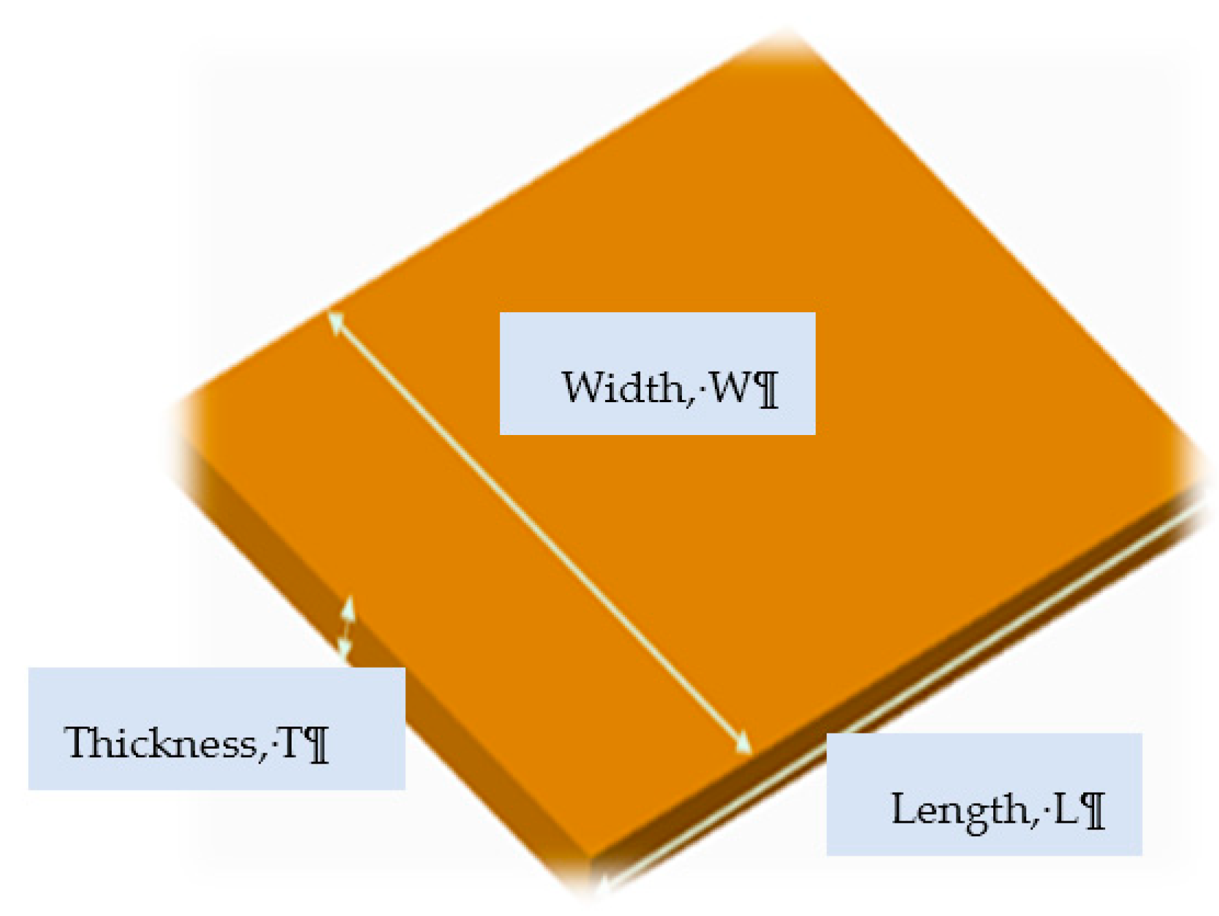
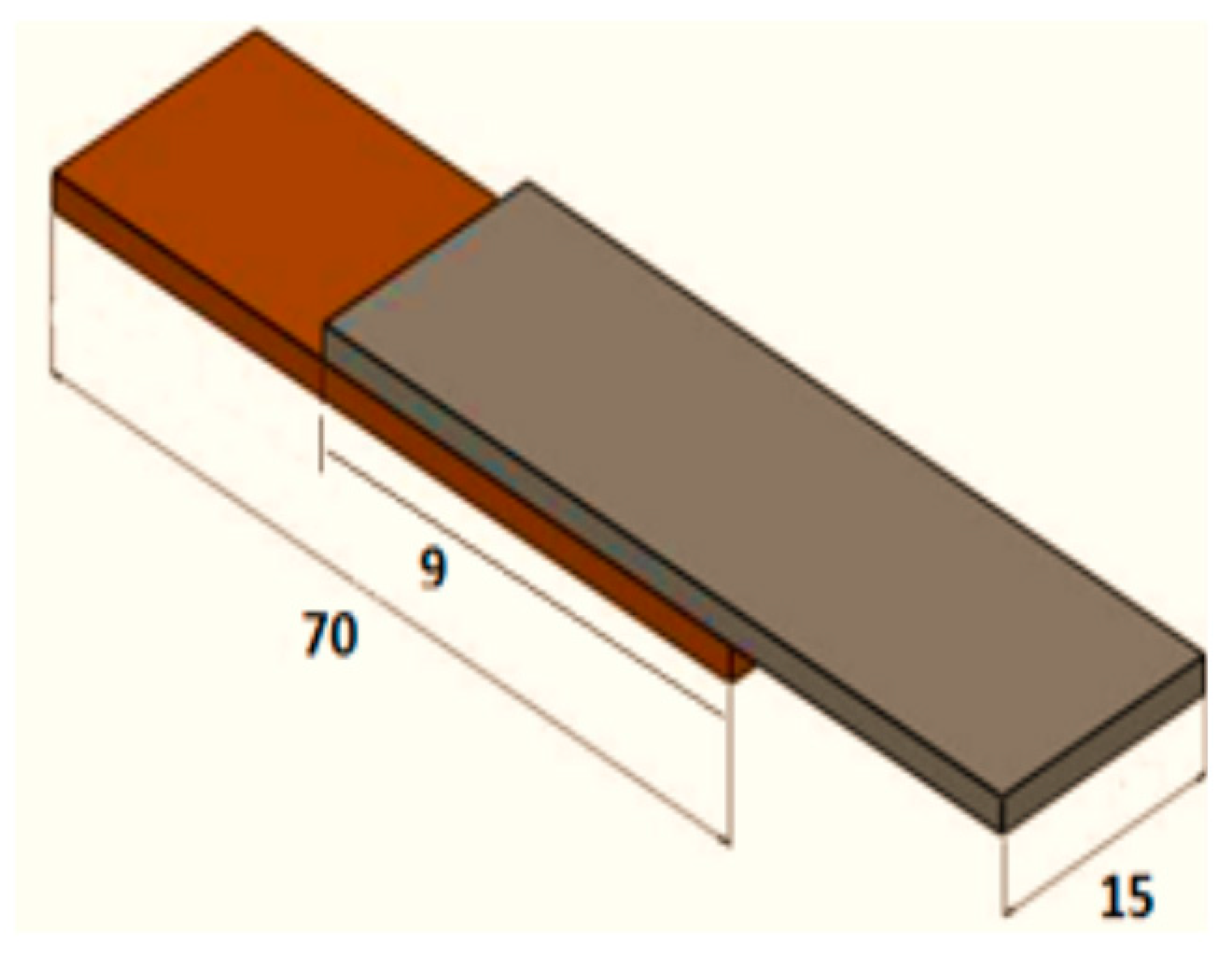
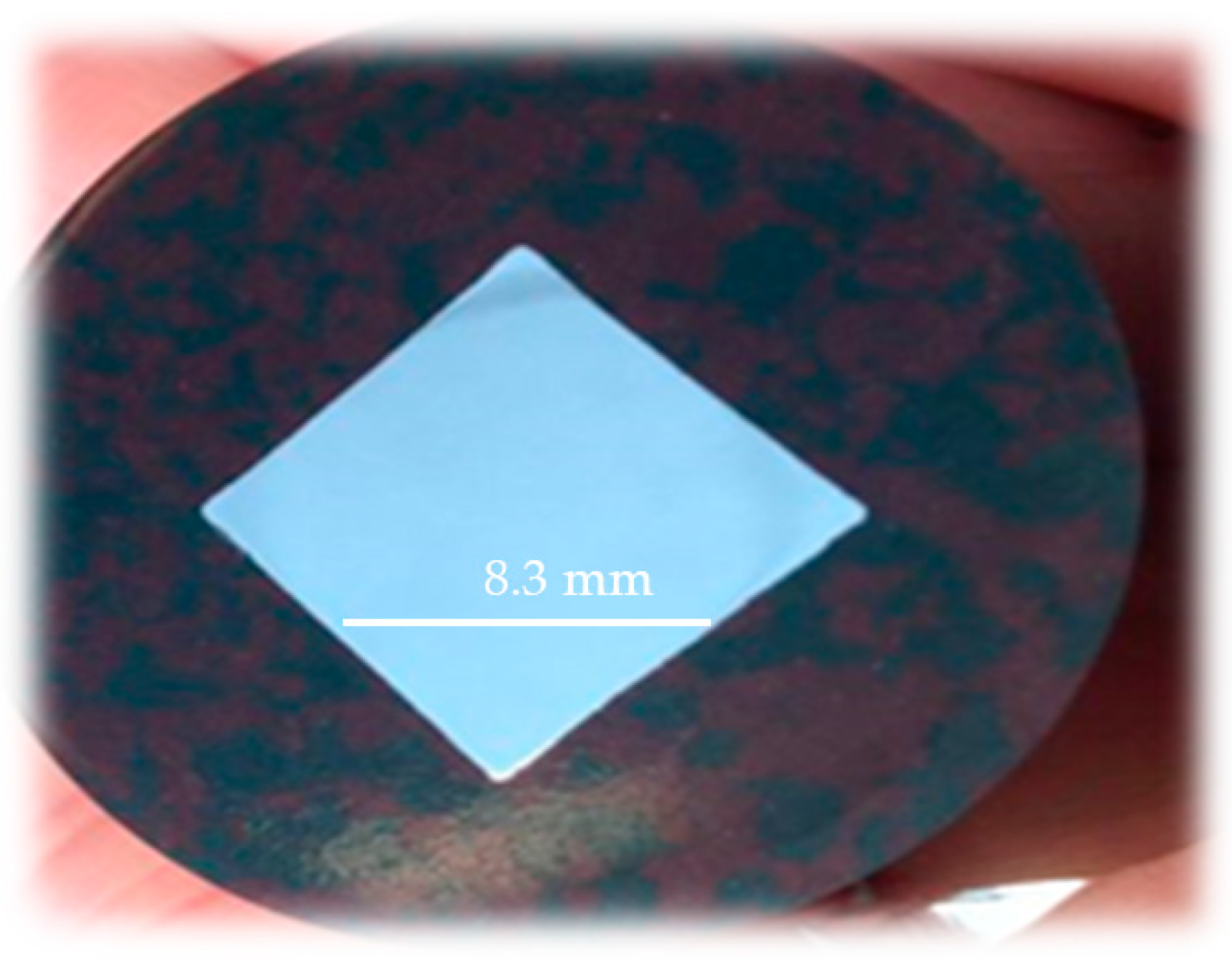
For the current investigations, three different materials namely 1060 Al (thick), 2219 Al (thin), and pure Cu as listed in Table 1 and three different tools such as high-speed cobalt taper-pin (HSCo) tool (HSCo), high-speed cobalt (HSCo) square-pin tool, and tungsten carbide (WC) square-pin tool were employed as shown in Figure 1 and specifications listed in Table 2. The stress–strain curve of each of the materials is shown in Figure 2 and the mechanical properties are presented in Table 3. The blank from each material was cut to the size of 100 mm × 70 mm, as shown in Figure 3. The surface oxides from the plates were removed using the abrasive paper. The plates were firmly held in a fixture shown in Figure 4. The FSW was performed along the long dimension of plates (i.e., rolling direction) utilizing the BYJC vertical milling machine. The tilt angle was kept constant at 2° and the dwell time ranged from 20–35 s. After welding, the strength of lap joints was characterized by conducting lap shear tests on the Universal Testing Machine 5567 (Instron Corp., Norwood, MA, USA): The geometry of the test sample is shown in Figure 5. To examine the microstructure and defects, samples (size: 16 mm × 16 mm) were cut using a CNC EDM wire cut machine and were ground with 220, 320, 500, 800, 1000, 2400, and 4000 abrasive papers of Silicon Carbide (Figure 6). The samples were thoroughly observed with the TESCAN scanning electron microscope (TESCAN, Brno, Czech Republic) and OLYMPUS B061 optical microscope (OLYMPUS, Tokyo, Japan). OMEGA infrared thermometer (OMEGA, Norwalk, USA) was utilized during friction stir welding to measure the temperature at the center on the top surface of the upper plate as shown in Figure 4.

3. Results and Discussion

3.1. Selection of Tool Geometry to Fabricate Dissimilar Al/Cu Lap Joints

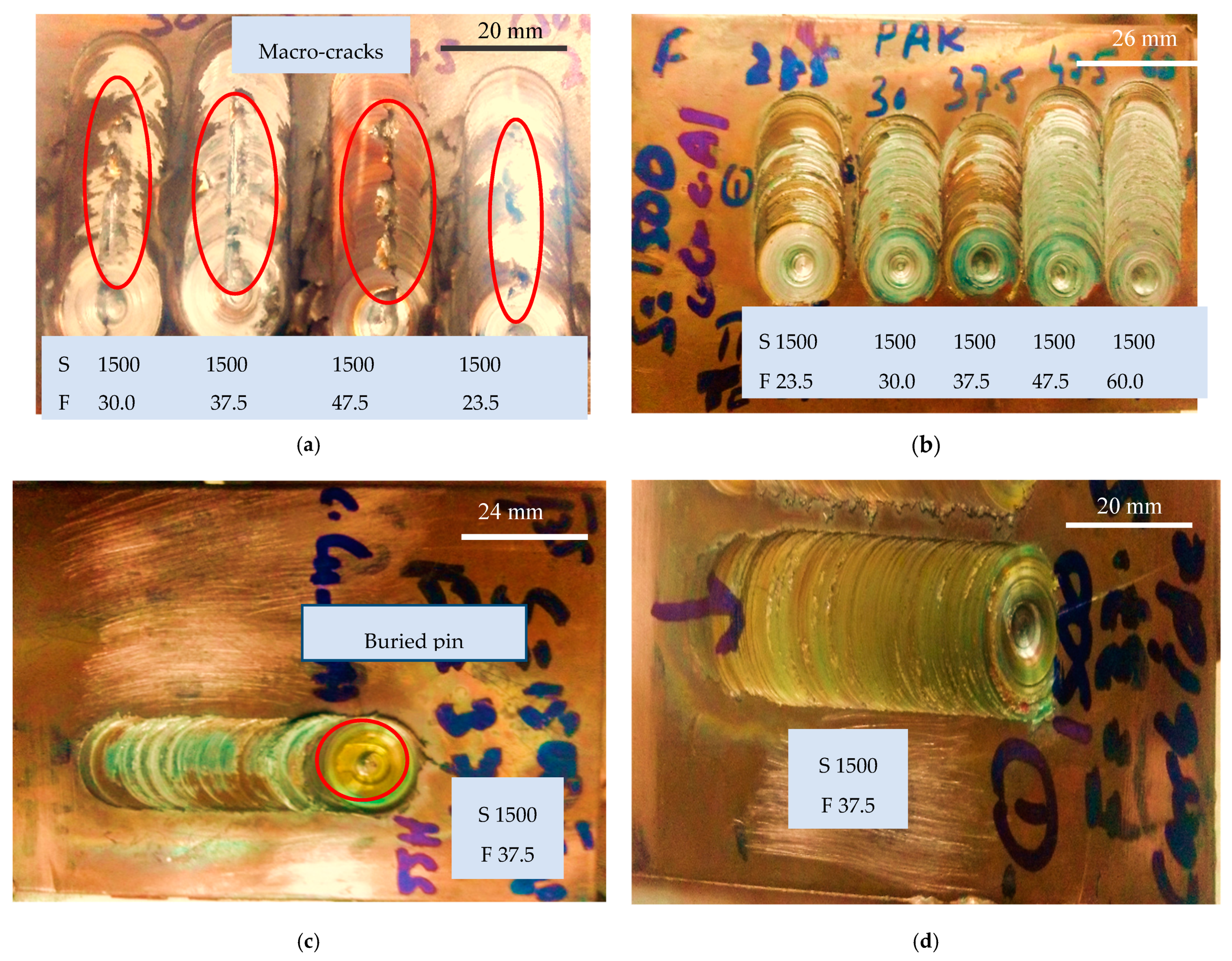
Experiments were performed to select suitable tool geometry to successfully produce Al/Cu lap joints. Based on literature reports [24,25,26], two shapes of pins namely round tapered and square were utilized (Figure 1). The shoulder diameter in each case was 16 mm, the pin height was 3.2 mm, and the other details were as listed in Table 2. The commercial Cu sheet (1.65 mm thick) was placed on the top of the 1060 Al sheet (4 mm thick) to fabricate dissimilar lap joint. The welding was performed employing the tapered-pin tool made of high-speed cobalt (HSCo) steel (Figure 1a). The attempts were made by employing the rotation speed of 1500 rpm and varying the feed from 23.5 mm/min to 47.5 mm/min as listed in Table 4. As shown in Figure 7a and indicated in Table 4, surface cracks were generated while welding thus rendering all of the attempts to be unsuccessful. Moreover, the HSCo tapered-pin tool was observed to have a shorter life in these tests wherein pin detachment led to complete failure of the tool.
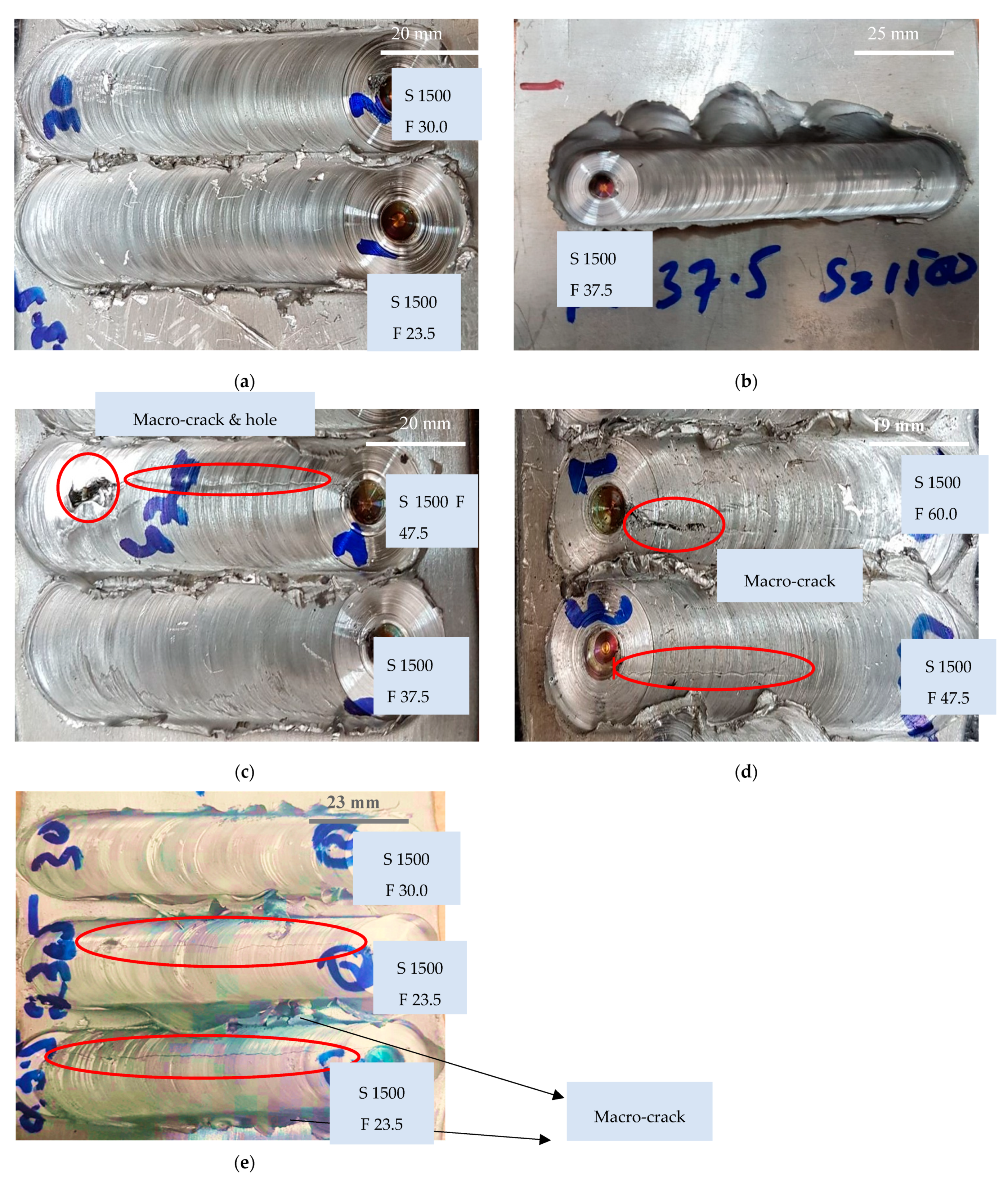
The second experimental plan was launched to select appropriate tool geometry with the square-pin tool. As summarized in Table 5, the square-pin tool contrary to the tapered-pin tool apparently produced successful joints as observable from Figure 7b,c. However, this tool also encountered failure after a few tests as indicated in Figure 7c whereby a pin left inside the material can be noticed. The observation from these primary tests revealed that the square-pin tool produced comparatively successful joints because its squared corners while rotating in a circle generates waves that help in the breaking and mixing of materials [24]. However, the issue regarding the breakage of the tool-pin that probably occurred due to tool softening owing to heating while welding yet needed to be resolved. Therefore, further tests were performed by varying the tool material (WC) as detailed in the coming section. A test experiment was performed through the WC square-pin tool exactly on the same parameters (S 1500 rpm and F 36.5 mm/min) as applied for the HSCo square-pin tool to check the success of the welded joint (Cu-Al) and the strength of WC tool as shown in Figure 7d.

3.2. Selection of Tool Material to Fabricate Dissimilar Al/Cu Lap Joints

In an attempt to opt an appropriate tool material for successful welding of Al/Cu joints, two dissimilar lap joints of 2219 Al-Cu and Cu-1060 Al were fabricated employing two types of tool materials namely HSCo Steel and WC Carbide. The pin geometry in both cases was square because, as found above, this geometry offered better results in comparison to other considered ones. The complete set of conditions has been listed in Table 6.
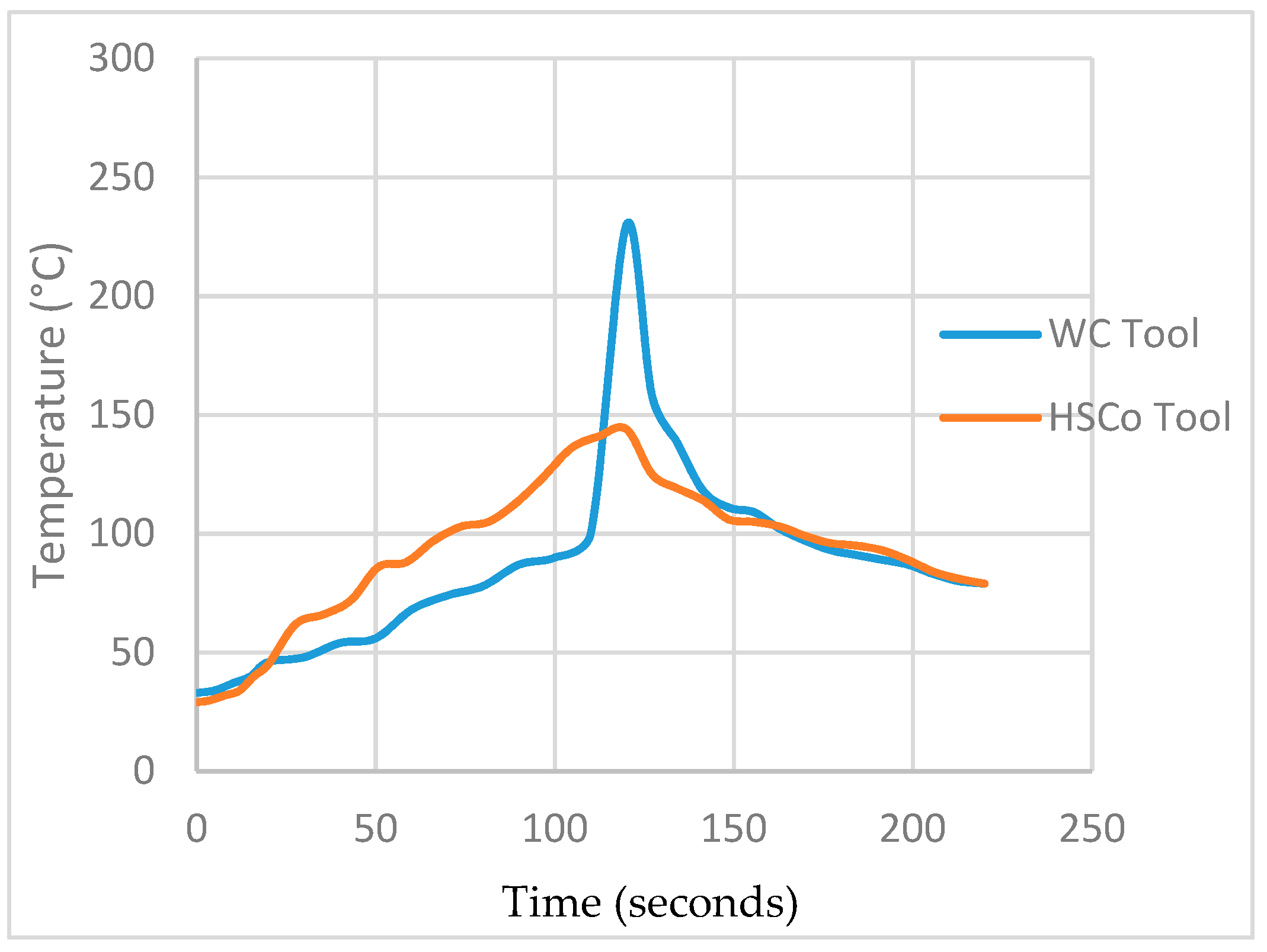
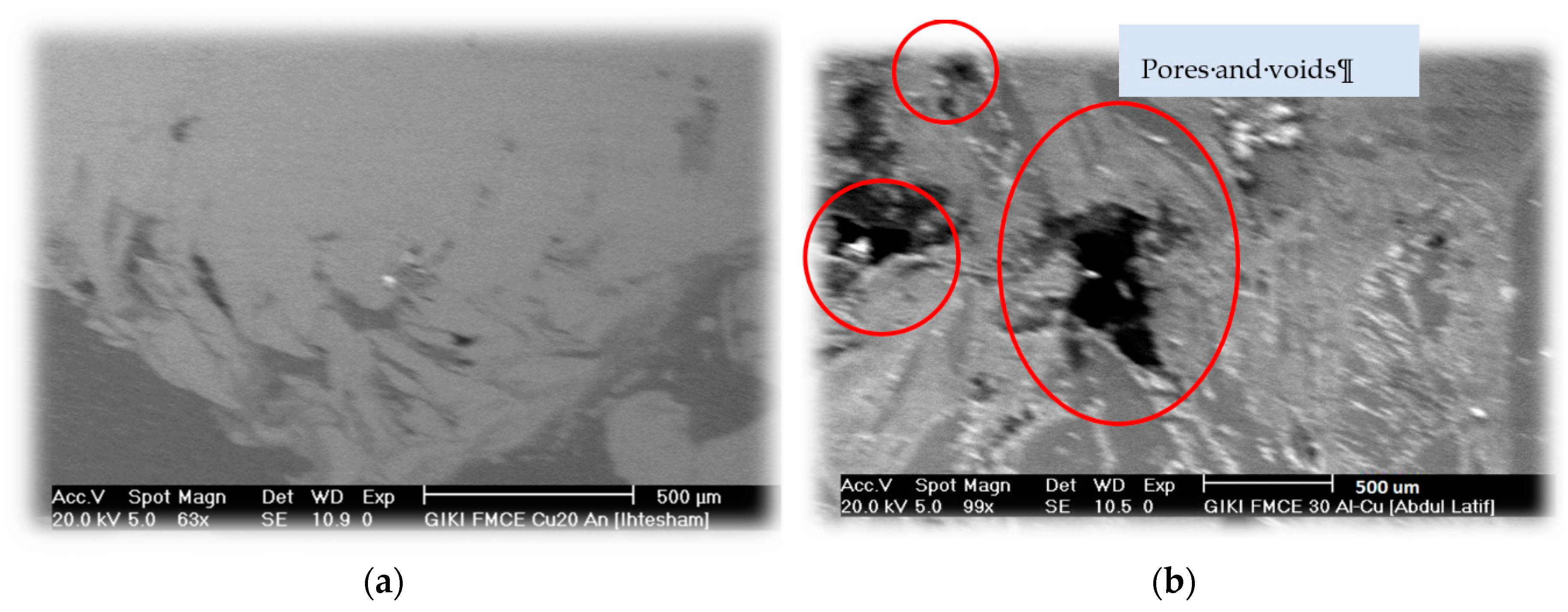
Lap shear tests were carried out in order to assess the mechanical performance of lap joints. The joints and their strength results are shown in Table 7. As observable, both 2219 Al-Cu and Cu-1060 Al dissimilar joints exhibit fairly good strength when welding was done utilizing the WC tool. Furthermore, the WC tool offers greater joint strength than the HSCo-Steel tool. For example, the joint strength of the 2219 Al-Cu joint is doubled when the tool material is altered from HSCo-steel to WC. The strength gain in the case of the Cu-1060 joint is even better (about 29 times). Figure 9 presents the temperature profiles recorded during welding. The peak temperature obtained with the WC tool is 250 °C and that obtained with HSCo-steel tool is 150 °C. This difference in the temperature is due to a fact that the WC material has higher conductivity (110 W/mK) than HSCo-steel (60 W/mK). As a result, the workpiece experiences greater heat input that in turn helps in proper mixing and defect free welding when the WC tool is employed. This can be witnessed from the SEM images shown in Figure 10 wherein joints produced with the WC tool are sound while those fabricated with the HSCo-steel tool suffer from defects like pores and voids. These shreds of evidence support why the WC tool produces sound joints with high strength.

3.3. Effect of Plate Positioning in Dissimilar Al/Cu Lap Joints

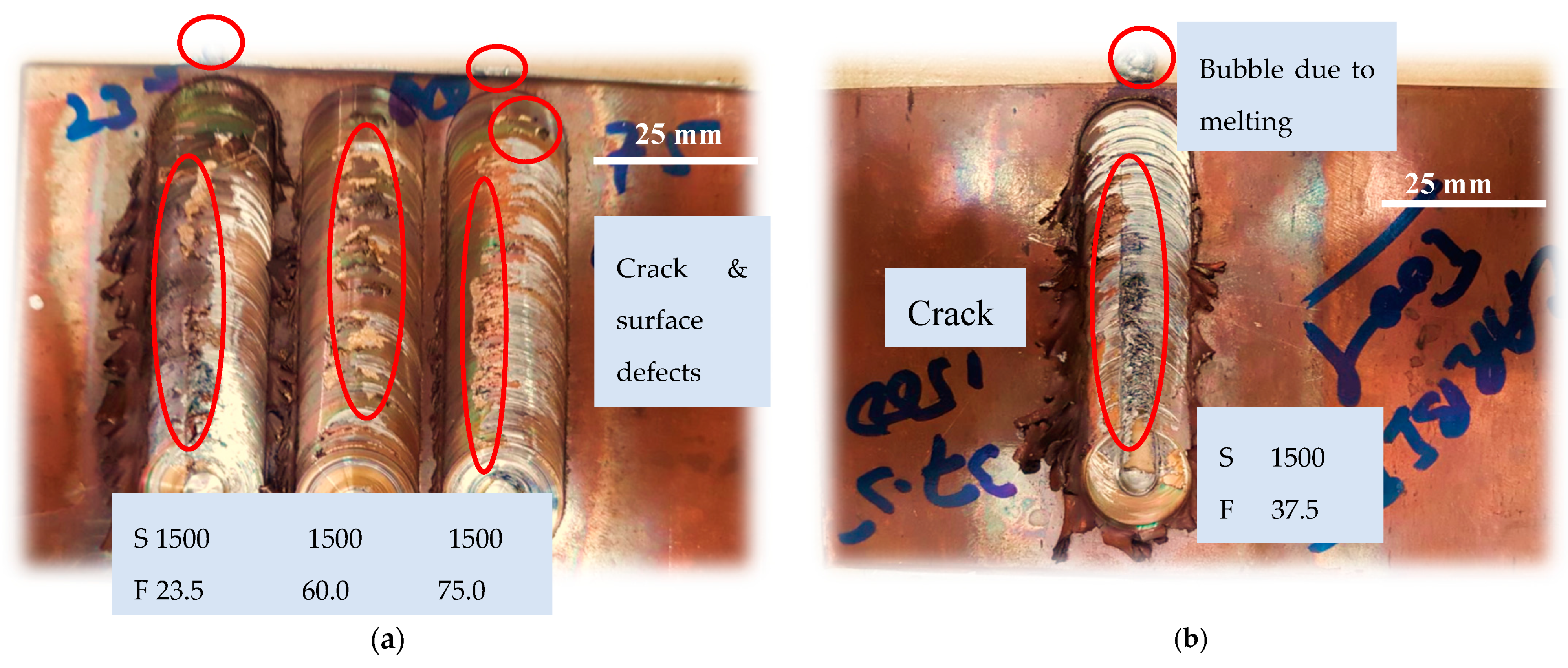
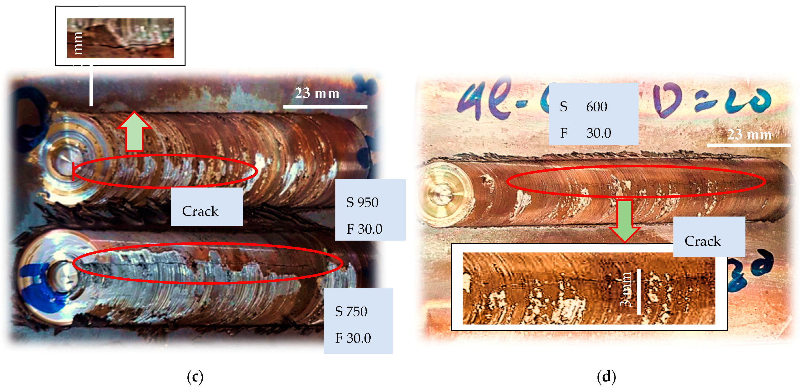
To compare the soundness of lap joints with respect to the position of the plates, initial experiments were performed keeping 2219 Al plate onto the Cu plate (1.65 mm). The joining was done using the WC tool and a range of welding speed as listed in Table 8. Successful joining in this stacking configuration was realized for the welding speed ranging from 23.5 mm/min to 37.5 mm/min (Figure 8 and Table 8). On the other hand, the entire range of joints remained unsuccessful when the Cu plate was stacked onto the Al plate (Table 9). In fact, the authors observed melting of the Al plate during welding as evidenced in Figure 11a,b. This observation points out that the Cu plate being very conductive radiated heat into the Al plate, and the heat was sufficient to cause melting of Al.
To reduce excessive heat generation, the rotational speed was decreased in steps from 1500 rpm to 600 rpm (Table 9). However, success could not be realized as the defects like cracks and holes occurred as observable from Figure 11c,d.

3.4. Role of Heat Sink in 2219 Al-Cu Lap Joints

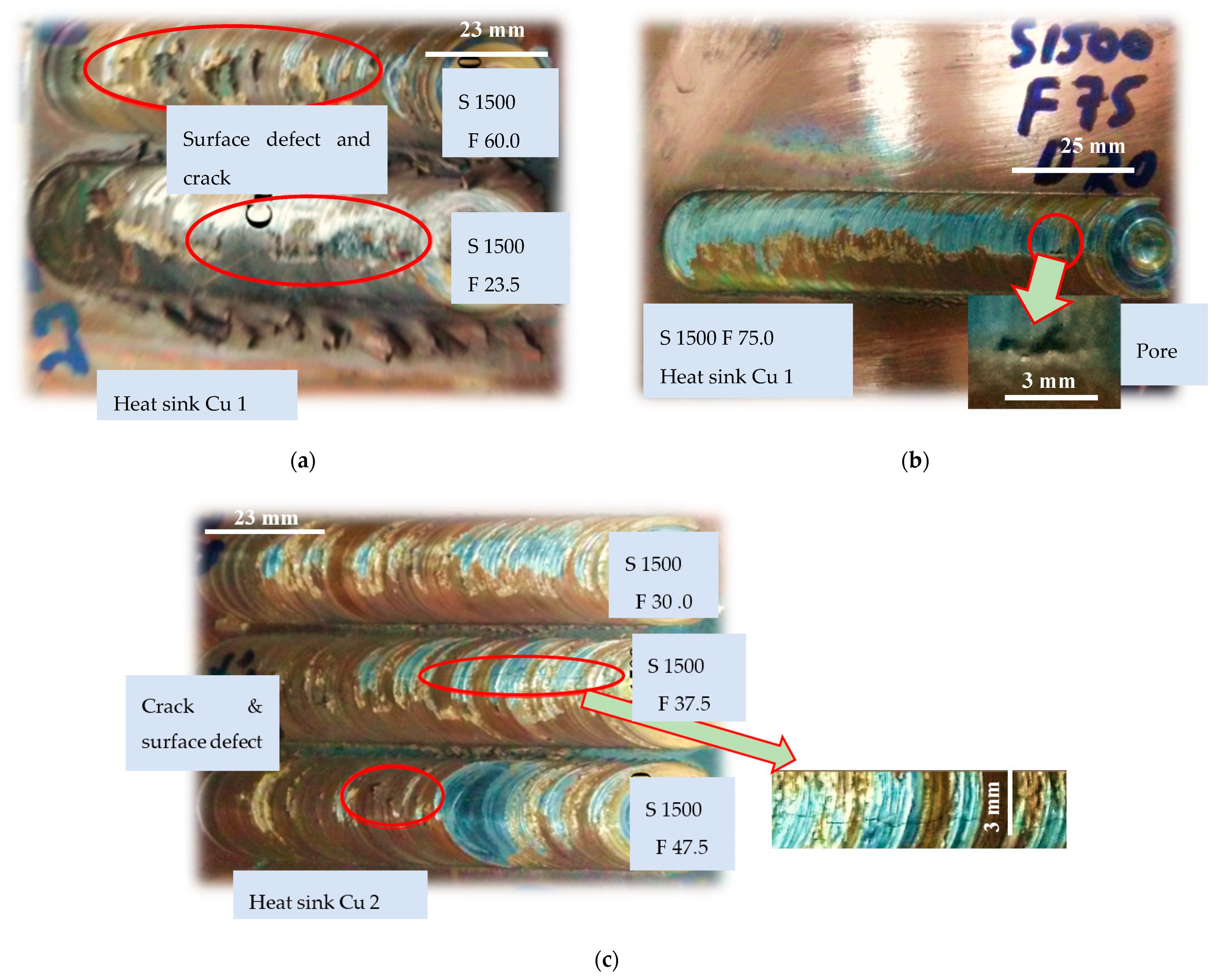
In order to avoid melting of the Al plate in the Cu-Al stacking configuration found earlier, a number of trials were made with having the Cu plate as a sink under the Al plate. Two plates of Cu with thickness of 1.65 mm and 3 mm were utilized. The welding speed was varied over a range as listed in Table 10. The cracks and flakes of Cu were observed in many instances although the quality of the weld joint was significantly improved in terms of bubbles formation and cracking in comparison to the scenario(s) when no heat sink was used. The sound joint was achieved when thicker heat sink (3 mm Cu plate) was placed and the joining was performed at the rotational speed of 1500 rpm and welding speed of 30 mm/min as indicated in Table 10.
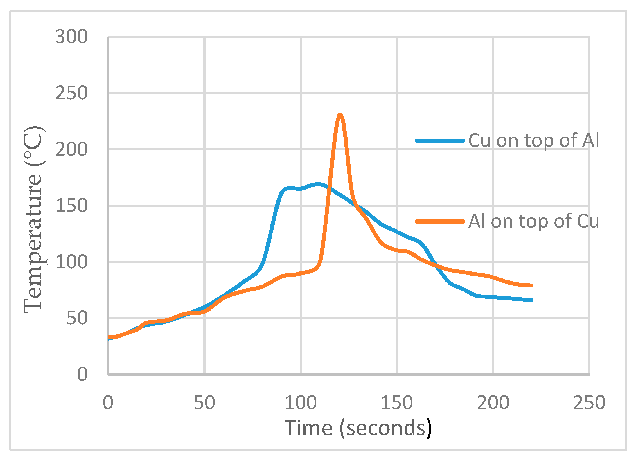
Table 11 compares the effect of stacking sequence on the joint strength. It can be noticed that the Al-Cu sequence offers around 4 times greater strength than the Cu-Al stacking. This happens due to a fact that the peaks temperature in Al-Cu stacking is 220 °C and that in Cu-Al stacking is 160 °C (Figure 13), which promotes material mixing and defect-free joining. Further, the cooling rate in the former case is higher that promotes the joint strength [27,28]. Moreover, Akbari et al. [14] have reported that weaker compounds are formed when joining is done with the Cu-Al stacking sequence. These, besides defects, impair the interfacial strength.

4. Conclusions

In the present study, investigations were conducted in order to produce sound Al/Cu dissimilar lap joints through friction stir welding. For this purpose, a number of process conditions including tool-pin shape, tool material, stacking sequence, workpiece material, heat sink, rotational speed, and welding speed were altered. To know their soundness in terms of defects and strength, the joints were subjected to microscopic and mechanical tests. The following important findings can be drawn from the study:
  • The HSCo-steel tool with tapered-pin does not adequately mix the materials to realize a sound joint. The successful joining is observed when the square-pin tool is employed.
  • The WC tool forms superior joints (in terms of defects and strength) than the HSCo-tool, attributing to a reason that greater peak temperature is achieved with the former tool (say 250 °C vs. 150 °C in case of 2219 Al-Cu joints). The former tool offers joint strength of 25 MPa in comparison to 13 MPa offered by the HSCo-tool. Moreover, the WC tool exhibits greater life than the HSCo-Steel tool.
  • Stacking sequence is one of the key factors to have a successful Al/Cu lap joint. The joining is realized only when the Al-Cu configuration is arranged. With an inverse arrangement (Cu-Al), Al plate melts down. However, use of heat sink proves beneficial to radiate the heat and thus for the successful joining in the Cu-Al stacking configuration. Additionally, sound joint in this configuration is achieved with a particular set of conditions, i.e., heat sink: 3 mm thick Cu plate, feed rate: 30 mm/min, speed: 1500 rpm, tilt angle: 2°, tool: WC with square-pin.

Author Contributions

Conceptualization, A.L., H.W. and G.H.; methodology, A.L. and H.W.; formal analysis, A.L., H.W., G.H. and B.H.; investigation, A.L., H.W. and G.H.; writing—original draft preparation, A.L. and H.W.; writing—review and editing, A.L., G.H., K.A. and B.H.; visualization, A.L. and H.W.; supervision, G.H.

Funding

The necessary funding to realize this work in the research community was provided by Fundamental Research Funds for the Central Universities (Grant No. NS2015055), High-End Foreign Experts Project with Universities directly under the Administration of Ministries and Commissions of the Central Government (Grant No. 011951G19061), National Natural Science Foundation of China (Grant No. 51105202) and State Administration of Foreign Experts Affairs PR China and Ministry of Education PR China (111 project, Grant No. B16024), for which the authors are grateful.

Acknowledgments

The authors are thankful to GIK Institute of Engineering Sciences and Technology (Pakistan) for providing advisory and technical support.

Conflicts of Interest

The authors declare no conflict of interest.

Abbreviations

SRotational speed
rpmRevolution per minute
FWelding speed
mm/minMillimeters per minute
CuCopper, Cu 1 thickness is 1.65 mm & Cu 2 thickness is 3 mm
Al-CuAluminum plate placed on the copper plate
Cu-AlCopper plate placed on the Al plate
Al/CuEither aluminum on top of copper or vice versa
HSCoHigh-speed cobalt
WCTungsten carbide
TDDwell time
T (°C)Temperature in centigrade

References

  1. Perrett, J.; Martin, J.; Threadgill, P.; Ahmed, M. Recent developments in friction stir welding of thick section aluminium alloys. In Proceedings of the 6th World Congress on Aluminium Two Thousand, Florence, Italy, 13–17 March 2007; pp. 13–17. [Google Scholar]
  2. Ji, F.; Xue, S.; Dai, W. Reliability studies of Cu/Al joints brazed with Zn–Al–Ce filler metals. Mater. Des. 2012, 42, 156–163. [Google Scholar]
  3. Kah, P.; Vimalraj, C.; Martikainen, J.; Suoranta, R. Factors influencing Al-Cu weld properties by intermetallic compound formation. Int. J. Mech. Mater. Eng. 2015, 10, 10. [Google Scholar] [CrossRef]
  4. Galvão, I.; Oliveira, J.; Loureiro, A.; Rodrigues, D. Formation and distribution of brittle structures in friction stir welding of aluminium and copper: Influence of shoulder geometry. Intermetallics 2012, 22, 122–128. [Google Scholar] [CrossRef]
  5. Shigematsu, I.; Kwon, Y.-J.; Suzuki, K.; Imai, T.; Saito, N. Joining of 5083 and 6061 aluminum alloys by friction stir welding. J. Mater. Sci. Lett. 2003, 22, 353–356. [Google Scholar] [CrossRef]
  6. Cao, X.; Jahazi, M. Effect of tool rotational speed and probe length on lap joint quality of a friction stir welded magnesium alloy. Mater. Des. 2011, 32, 1–11. [Google Scholar] [CrossRef]
  7. Xu, N.; Ueji, R.; Fujii, H. Dynamic and static change of grain size and texture of copper during friction stir welding. J. Mater. Process. Technol. 2016, 232, 90–99. [Google Scholar] [CrossRef] [Green Version]
  8. Galvao, I.; Oliveira, J.; Loureiro, A.; Rodrigues, D. Formation and distribution of brittle structures in friction stir welding of aluminium and copper: Influence of process parameters. Sci. Technol. Weld. Join. 2011, 16, 681–689. [Google Scholar] [CrossRef]
  9. Luo, H.; Wu, T.; Wang, P.; Zhao, F.; Wang, H.; Li, Y. Numerical Simulation of Material Flow and Analysis of Welding Characteristics in Friction Stir Welding Process. Metals 2019, 9, 621. [Google Scholar] [CrossRef]
  10. Dialami, N.; Cervera, M.; Chiumenti, M. Numerical modelling of microstructure evolution in friction stir welding (FSW). Metals 2018, 8, 183. [Google Scholar] [CrossRef]
  11. El Chlouk, Z.G.; Achdjian, H.H.; Ayoub, G.; Kridli, G.T.; Hamade, R.F. The Effect of Tool Geometry on Material Mixing during Friction Stir Welding (FSW) of Magnesium AZ31B Welds. In Proceedings of the TMS Middle East-Mediterranean Materials Congress on Energy and Infrastructure Systems (MEMA 2015), Doha, Qatar, 11–14 January 2015; pp. 235–242. [Google Scholar]
  12. Patel, V.; Li, W.; Wang, G.; Wang, F.; Vairis, A.; Niu, P. Friction Stir Welding of Dissimilar Aluminum Alloy Combinations: State-of-the-Art. Metals 2019, 9, 270. [Google Scholar] [CrossRef]
  13. Sharma, N.; Siddiquee, A.N.; Khan, Z.A.; Mohammed, M.T. Material stirring during FSW of Al–Cu: Effect of pin profile. Mater. Manuf. Processes 2018, 33, 786–794. [Google Scholar] [CrossRef]
  14. Akbari, M.; Abdi Behnagh, R.; Dadvand, A. Effect of materials position on friction stir lap welding of Al to Cu. Sci. Technol. Weld. Join. 2012, 17, 581–588. [Google Scholar] [CrossRef]
  15. Bisadi, H.; Tavakoli, A.; Sangsaraki, M.T.; Sangsaraki, K.T. The influences of rotational and welding speeds on microstructures and mechanical properties of friction stir welded Al5083 and commercially pure copper sheets lap joints. Mater. Des. 2013, 43, 80–88. [Google Scholar] [CrossRef]
  16. Celik, S.; Cakir, R. Effect of friction stir welding parameters on the mechanical and microstructure properties of the Al-Cu butt joint. Metals 2016, 6, 133. [Google Scholar] [CrossRef]
  17. Karimi, N.; Nourouzi, S.; Shakeri, M.; Habibnia, M.; Dehghani, A. Effect of tool material and offset on friction stir welding of Al alloy to carbon steel. Adv. Mater. Res. 2012, 445, 747–752. [Google Scholar] [CrossRef]
  18. Çevik, B.; Özçatalbaş, Y.; Gülenç, B. Effect of tool material on microstructure and mechanical properties in friction stir welding. Mater. Test. 2016, 58, 36–42. [Google Scholar] [CrossRef]
  19. Bozkurt, Y.; Boumerzoug, Z. Tool material effect on the friction stir butt welding of AA2124-T4 Alloy Matrix MMC. J. Mater. Res. Technol. 2018, 7, 29–38. [Google Scholar] [CrossRef]
  20. Wiedenhoft, A.G.; Amorim, H.J.; Rosendo, T.S.; Strohaecker, T.R. Friction Stir Welding of Dissimilar Al-Cu Lap Joints with Copper on Top. Key Eng. Mater. 2017, 724, 71–76. [Google Scholar] [CrossRef]
  21. Wiedenhoft, A.G.; de Amorim, H.J.; Rosendo, T.d.S.; Tier, M.A.D.; Reguly, A. Effect of Heat Input on the Mechanical Behaviour of Al-Cu FSW Lap Joints. Mater. Res. 2018, 21. [Google Scholar] [CrossRef]
  22. Marstatt, R.; Krutzlinger, M.; Luderschmid, J.; Constanzi, G.; Mueller, J.; Haider, F.; Zaeh, M. Intermetallic layers in temperature controlled Friction Stir Welding of dissimilar Al-Cu-joints. IOP Conf. Ser. Mater. Sci. Eng. 2018, 373, 012017. [Google Scholar] [CrossRef]
  23. Mubiayi, M.P.; Akinlabi, E.T. Friction stir welding of dissimilar materials between aluminium alloys and copper, An overview. In Proceedings of the World Congress on Engineering, London, UK, 3–5 July 2013; pp. 3–5. [Google Scholar]
  24. Patel, J.B.; Bhatt, K.; Shah, M. Replacement of Tool-pin Profile and Simulation of Peak Temperature & Flow Stress during FSW of AA6061 Alloy. IJISET 2014, 1, 273–276. [Google Scholar]
  25. Sahu, P.K.; Kumari, K.; Pal, S.; Pal, S.K. Hybrid fuzzy-grey-Taguchi based multi weld quality optimization of Al/Cu dissimilar friction stir welded joints. Adv. Manuf. 2016, 4, 237–247. [Google Scholar] [CrossRef]
  26. Buffa, G.; De Lisi, M.; Sciortino, E.; Fratini, L. Dissimilar titanium/aluminum friction stir welding lap joints by experiments and numerical simulation. Adv. Manuf. 2016, 4, 287–295. [Google Scholar] [CrossRef]
  27. Humphreys, F.J.; Hatherly, M. Recrystallization and Related Annealing Phenomena; Elsevier: Oxford, UK, 2012. [Google Scholar]
  28. Nelson, T.; Steel, R.; Arbegast, W. In situ thermal studies and post-weld mechanical properties of friction stir welds in age hardenable aluminium alloys. Sci. Technol. Weld. Join. 2003, 8, 283–288. [Google Scholar] [CrossRef]
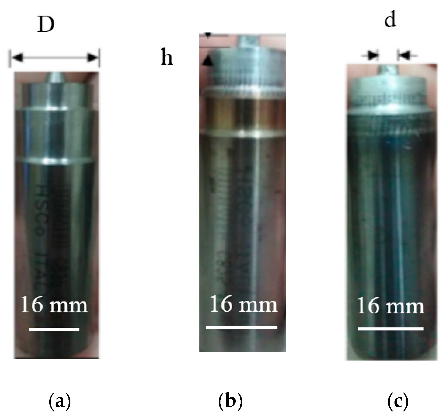
Figure 1. Tool geometries employed in the present study: (a) HSCo tapered tool; (b) HSCo squared tool; and (c) WC squared tool.
Metals 09 00875 g001
Figure 2. Stress–strain curve for: (a) 2.15 mm 2219 Al, (b) 4 mm 1060 Al, (c) 3 mm Cu, and (d) 1.65 mm Cu.
Metals 09 00875 g002
Figure 3. Schematics of friction stir welding (FSW) lap sample.
Metals 09 00875 g003
Figure 4. Setup for clamping FSW sample.
Metals 09 00875 g004
Figure 5. Lap shear sample.
Metals 09 00875 g005
Figure 6. Microscopy and micro-hardness sample.
Metals 09 00875 g006
Figure 7. 1060Al-Cu lap joints produced; HSCo (a) tapered-pin tool, (b,c) square-pin tool, and (d) tungsten carbide (WC) square-pin tool.
Metals 09 00875 g007
Figure 8. Dissimilar 2219 Al-Cu lap joints fabricated employing different tool materials: (ad) WC square-pin tool at scale, (e) HSCo square-pin tool.
Metals 09 00875 g008
Figure 9. Effect of tool material on temperature profiles during FSW of 2219 Al-Cu joints with square-pin tools.
Metals 09 00875 g009
Figure 10. Scanning electron microscopy of 2219Al-Cu lap joint at F 30.0 mm/min using (a): WC tool, (b) HSCo square- tool.
Metals 09 00875 g010
Figure 11. Dissimilar Cu-2219 Al lap joints fabricated by WC square-tool.
Metals 09 00875 g011aMetals 09 00875 g011b
Figure 12. Redesign of dissimilar Cu-2219 Al lap joints fabricated by WC square-tool and using heat sink: (a,b) Cu 1 and (c) Cu 2.
Metals 09 00875 g012
Figure 13. Temperature distribution curves of 2219 Al-Cu and Cu-2219 Al fabricated by WC at S 1500 rpm and F 30.0 mm/min.
Metals 09 00875 g013
Table 1. Blank size utilized in the present study.
MaterialLength (mm), LWidth (mm), WThickness (mm), T
1060 Al100704
2219 Al100702.15
Commercial Cu 1100701.65
Commercial Cu 2100703
Table 2. Specifications of FSW tools.
ToolShoulder Diameter (mm)Pin Height (mm)Pin Cross Section Dimension (mm)
HSCo Tapered Tool163.2Small diameter = 3 Large diameter = 5
HSCo Squared Tool163.2Squared shaped each side = 4
Carbide Squared Tool163.2Squared shaped each side = 4
Table 3. Mechanical properties of base metals.
MaterialYield Strength (MPa),YSUltimate Tensile Strength (MPa), UTS%Elongation (mm/mm), eVicker’s Micro-Hardness at 1 gm
1060 Al181.72248.6617.6981.12
2219 Al60.42117.9719.7552.02
Commercial Cu 1219.21248.8536.56107.71
Commercial Cu 2291.18303.8619.48112.21
Table 4. Experimental conditions employed to fabricate Cu 1-1060Al lap joints using HSCo-steel tapered-pin tool ( T D : 22 s).
Test no.S, rpmF, mm/minRemark
1150023.5Crack as shown in Figure 7a
230.0Crack as shown in Figure 7a
337.5Crack as shown in Figure 7a
447.5Crack as shown in Figure 7a
Table 5. Experimental conditions employed to fabricate Cu 1-1060Al lap joints using HSCo square-pin tool ( T D : 22 s).
Test No.S, rpmF, mm/minRemark
1150023.5Successful as shown in Figure 7b
230.0Successful as shown in Figure 7b
337.5Successful as shown in Figure 7b
447.5Successful as shown in Figure 7b
560.0Successful as shown in Figure 7b
Table 6. Fabrication of 2219 Al-Cu (1.65 mm) lap joint using WC and HSCo square-pin tool ( T D : 22 s).
Test No.S, rpmF, mm/minToolRemarks
1150023.5WCSuccessfully fabricated (Figure 8a)
230.0Successfully fabricated (Figure 8a)
337.5Successfully fabricated (Figure 8b)
447.5Crack and hole occurred (Figure 8c)
560.0Crack occurred (Figure 8d)
1150023.5HSCoCrack occurred (Figure 8e)
230.0Successfully fabricated (Figure 8e)
337.5Successfully fabricated
447.5Crack occurred
Table 7. Comparison of joint strength between dissimilar lap joints fabricated with WC and HSCo-steel tools.
S. #Lap JointsF mm/minJoint Strength (MPa) by WC ToolJoint Strength (MPa) by HSCo Tool
12219 Al-Cu30.025.3
Metals 09 00875 i001
13.1
Metals 09 00875 i002
2Cu-1060 Al37.517.8
Metals 09 00875 i003
0.58
Metals 09 00875 i004
Table 8. Experiments for fabricating 2219Al-Cu lap joint using WC square-pin tool ( T D : 22 s).
Test No.S, rpmF, mm/minRemarks
1150023.5Successfully fabricated (Figure 8a)
230.0Successfully fabricated (Figure 8a)
337.5Successfully fabricated (Figure 8b,c)
447.5Crack occurred (Figure 8c,d)
560.0Cracks occurred (Figure 8d)
Table 9. Experiments for fabricating Cu -2219Al lap joint using WC square-pin ( T D : 20 s).
Test No.S, rpmF, mm/minRemarks
1150023.0Cracks and bubbles occurred (Figure 11a)
2150037.5Cracks hole and bubbles occurred (Figure 11b)
3150060.0Cracks occurred (Figure 11a)
4150075.0Cracks and bubbles occurred (Figure 11a)
595030.0Cracks occurred (Figure 11c)
675030.0Cracks occurred (Figure 11c)
760030.0Cracks occurred (Figure 11d)
Table 10. Experiments to fabricate dissimilar Cu-2219 Al lap joint with WC square-tool using heat sink ( T D : 20 s).
S, 1500 rpmHeat sink FRemarks
Test No.Cu 1
123.5Cracks occurred (Figure 12a)
260.0Surface defect and crack occurred (Figure 12a)
375.0Small pore occurred (Figure 12b)
4Cu 230.0Successfully fabricated (Figure 12c)
537.5Crack occurred (Figure 12c)
647.5Pore occurred (Figure 12c)
Table 11. Effect of plate position on the strength of lap joint.
S. #Lap JointsF, mm/min Joint Strength (MPa) by WC Tool
12219 Al-Cu30.025.3
Metals 09 00875 i005
2Cu-2219 Al30.0 5.9
Metals 09 00875 i006