Article

Electronic Structure Calculations of Oxygen Atom Transport Energetics in the Presence of Screw Dislocations in Tungsten

1
Department of Materials Science and Engineering, University of California Los Angeles, Los Angeles, CA 90095, USA
2
Department of Metallurgy, Materials Science and Engineering, Institut Jean Lamour, Université de Lorraine, Campus ARTEM, Allée André Guinier, F-54011 Nancy, France
3
Laboratory of Excellence on Design of Alloy Metals for low-mAss Structures (DAMAS), Universitat de Lorraine, F-57073 Metz, France
4
Department of Mechanical and Aerospace Engineering, University of California Los Angeles, Los Angeles, CA 90095, USA
*
Author to whom correspondence should be addressed.
Metals 2019, 9(2), 252; https://doi.org/10.3390/met9020252
Submission received: 13 December 2018 / Revised: 12 February 2019 / Accepted: 15 February 2019 / Published: 20 February 2019
(This article belongs to the Special Issue Advanced Tungsten Materials)

Abstract

:
Plastic flow in body-centered cubic (bcc) alloys is governed by the thermally-activated motion of screw dislocations in close-packed planes. In bcc interstitial solid solutions, solute diffusion can occur at very fast rates owing to low migration energies and solute concentrations. Under mechanical loading, solutes may move on the same or similar time scale as dislocations glide, even at low temperatures, potentially resulting in very rich co-evolution processes that may have important effects in the overall material response. It is therefore important to accurately quantify the coupling between interstitial impurities and dislocations, so that larger-scale models can correctly account for their interactions. In this paper, we use electronic structure calculations to obtain the energetics of oxygen diffusion under stress and its interaction energy with screw dislocation cores in bcc tungsten. We find that oxygen atoms preferentially migrate from tetrahedral to tetrahedral site with an energy of 0.2 eV. This energy couples only weakly to hydrostatic and deviatoric deformations, with activation volumes of less than 0.02 and 0.02 b 3 , respectively. The strongest effect is found for the inelastic interaction between O atoms and screw dislocation cores, which leads to attractive energies between 1.2 and 1.9 eV and sometimes triggers a transformation of the screw dislocation core from an easy core configuration to a hard core configuration.

1. Introduction

Refractory transition metals such as those in Groups V and VI of the periodic table belong to a class of materials with important potential applications thanks to their high-temperature strength and corrosion resistance [1,2,3]. However, they typically display poor low-temperature fracture toughness and must be alloyed with other transition metal elements to improve their ductility. For example, in the case of body-centered cubic (bcc) W, W-Re alloys have been shown to lower the ductile-to-brittle transition temperature by up to hundreds of degrees [4], resulting in commercially-viable alloys. Interstitial impurities, however, are known to produce marked increases in the ductile-to-brittle transition temperature of polycrystalline specimens [5]. Specifically, oxygen is seen to lower both the tensile and yield strengths, while promoting intergranular fracture at concentrations as low as 30 appm. In single crystals, the effect is less pronounced, although some evidence suggests a hardening effect at low temperatures [6,7,8]. In addition, oxygen is known to be involved in dynamic strain aging in tungsten-based alloys deformed within a certain strain rate and temperature window [9,10]. In principle, O is soluble in tungsten up to the formation of the line compound WO 2 at 66.7 at.% [11], although embrittling second phases have been seen to form at grain boundaries at only a few appm of concentration [12]. In single crystals, the effect can be isolated to dislocation core/solute interactions, particularly screw dislocations, as they are known to control plasticity in bcc metals at low-to-intermediate temperatures [13,14,15]. By its very nature, this interaction can only be studied using atomistic resolution methods to describe the large deformations found around the dislocation core. At the same time, the method must capture the essential details of W-O chemistry, which may become important in non-dilute conditions. These restrictions point to density functional theory (DFT) as the technique of choice to investigate dislocation–O interactions in W.
Numerous studies have been performed on dislocation core/solute interactions using DFT calculations. For substitutional solutes, several works including face and body-centered materials exist [16,17,18,19,20,21,22,23], while for interstitial impurities, several calculations including a number of different solutes in Fe have been recently published [24,25,26], as well as dislocation-C interactions in most bcc transition metals [27]. These calculations show that solute atoms stabilize the hard core configuration of a screw dislocation when the solutes are placed inside the triangular prism formed by the three 111 atomic rows enclosing the dislocation core.
Interestingly, despite its technological importance, no DFT studies have been performed on the interactions between dislocation and O in W. The primary objective of this work is to investigate the interactions of oxygen interstitial solute with screw dislocations in bcc W. These interactions can be categorized as long-range, i.e., elastic interactions affecting the diffusive behavior of oxygen atoms in the presence of dislocations, or short-range, i.e., local binding of a chemical nature between dislocation cores and impurities. Consequently, here, we study first the dependence on stress of the diffusivity of O interstitial atoms in bulk W, followed by the calculation of interaction energies between O atoms and screw dislocation cores. We end the paper with a discussion and the conclusions.

2. Computational Details

All DFT calculations were carried out using the Vienna Ab Initio Simulation Package (VASP) code [28] and the projector augmented wave (PAW) [29,30] pseudopotential scheme within the Perdew–Burke–Ernzerhof (PBE) generalized gradient approximation and a 400-eV kinetic-energy cutoff. The Hermite-Gaussian scheme was employed, with a smearing of 0.2 eV for electronic occupation. Structure relaxation was performed until the forces on all the atoms were less than 2 × 10 2 eV/Å.

2.1. O Solution and Migration Energies under Strain

Calculations of O-atom solution and migration energy in bulk W were performed using 250-atom bcc supercells with a 4 × 4 × 4 k-point grid. The migration barrier was calculated between two neighboring configurations of lowest energy (tetrahedral sites in the present case) using the nudged elastic band (NEB) method as implemented in VASP. O migration in bulk W under strain was investigated by applying the following transformation matrices to the supercell lattice vectors:
a = ε + I a
where a are the deformed lattice vectors, ε is the applied strain tensor, I is the identity tensor, and a are the undeformed lattice vectors. The undeformed configuration is expressed in a canonical Cartesian reference system with a 1 a 0 0 0 , a 2 = 0 a 0 0 , and a 3 0 0 a 0 , where a 0 = 3.168 Å is the lattice parameter of W calculated with the pseudopotential employed here. Two different strain tensors were applied for the simulations:
(i)
Hydrostatic strain:
ε = ϵ 0 0 0 ϵ 0 0 0 ϵ
(ii)
Volume-conserving shear:
ε = 0 γ / 2 0 γ / 2 0 0 0 0 0
where ϵ and γ are the applied dilatational and shear strains, respectively. Positive values of ϵ are taken to represent tensile distortions. Note that in the limit of small deformations, (i) the volumetric strain ε v = Δ V / V Tr ( ε ) = 3 ϵ and (ii) γ = tan θ , with θ the shear angle as defined in Figure 1. Note that shear deformation turns a symmetric cubic cell into a monoclinic one, which results in a shortening of certain tetrahedral→tetrahedral paths and in the extension of others, as illustrated in the figure. This is equivalent to applying negative shear strain, and consequently, we have investigated both reaction paths when calculating O migration in sheared bcc W. We used 10 NEB images in the majority of the cases considered here, the only exceptions being ϵ = 1 % , 2 % and γ = 1 % , where seven images where used.

2.2. Screw Dislocation–O Interaction

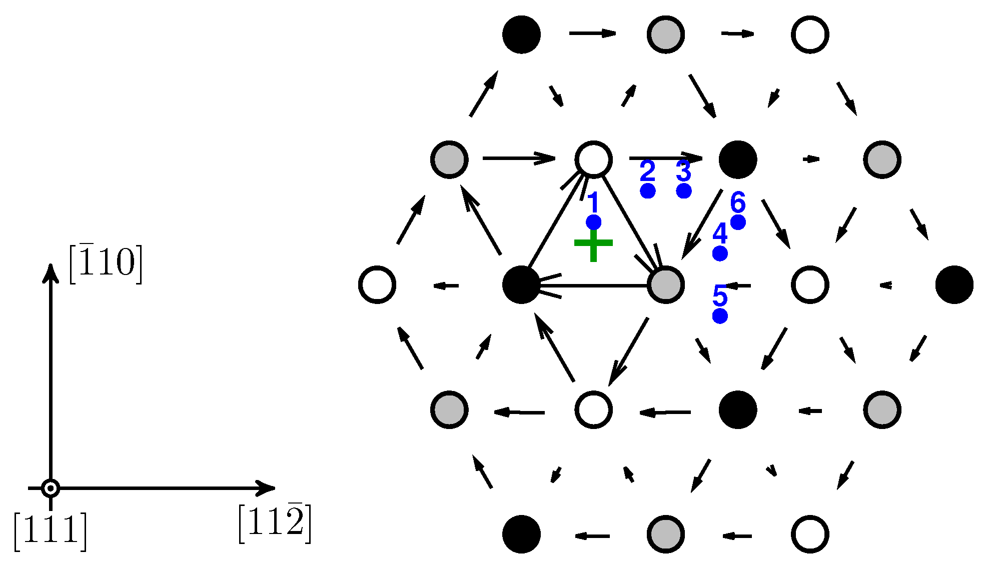
Simulations of dislocation–O interactions were performed using 135 W-atom supercells containing two screw dislocation cores with Burgers vectors + b and b ( b = a 0 / 2 [ 111 ] ) arranged in a balanced quadrupolar configuration, as is typically used for such simulations [31,32,33], with a 1 × 2 × 16 k-point grid. The cell was first relaxed in the absence of oxygen to determine the reference configuration for dislocation–solute interactions. This results in a non-degenerate, easy core configuration, consistent with a number of other independent DFT calculations [32,33,34,35,36,37]. Solute atoms were subsequently placed at various tetrahedral sites around both dislocation cores to ensure symmetric structures with equivalent energies. Figure 2 represents an expanded view of one of the dislocation cores of the supercell in order to highlight the six tetrahedral sites investigated as initial positions of the O atom. A differential displacement map is used to identify the position of the dislocation in the figure [38,39]. The use of periodic boundary conditions along the [ 111 ] direction when placing an O atom in the supercell results in a row of atoms separated by a distance of 1 b (equal to the thickness of the box). We tested the impact of using such thin specimens by repeating one of the calculations with a thickness of 2 b to preliminarily quantify the box thickness effect on the final results.

3. Results

3.1. Oxygen Atom Stability in Bulk Tungsten

Oxygen stability in bulk W was evaluated by separately inserting one oxygen atom in tetrahedral and octahedral sites of a bulk W bcc structure. Figure 3 shows the geometric location of the interstices in a bcc unit cell. The solution energy H s (heat of solution) is defined as:
H s = E W O E W μ O
where E W O and E W are, respectively, the energies of a W cell with and without O and μ O is the reference energy of a single O atom (chemical potential). In accordance with previous works [21,40], we took μ O to be half of the total energy of a O 2 molecule, which was calculated to be 4.92 eV (compared to 1.59 eV for an isolated O atom in a vacuum), i.e.,:
μ O = 1 2 E O 2 = 4.92 eV
With this, we found solution energies of 1.01 eV and 0.70 eV for for octahedral and tetrahedral sites, respectively. While this is consistent with recent studies in W-O [41,42], it deviates from what was found in other bcc metals, where octahedral sites were more stable for interstitial impurities (this is consistent with an octahedral volume of V oct = a 0 3 / 3 , versus a tetrahedral one of V tet = a 0 3 / 12 ) [26]. The reasons behind this behavior appear to be related to the overlap between the electron charge densities of O and W when the O atom is at a tetrahedral location [41].
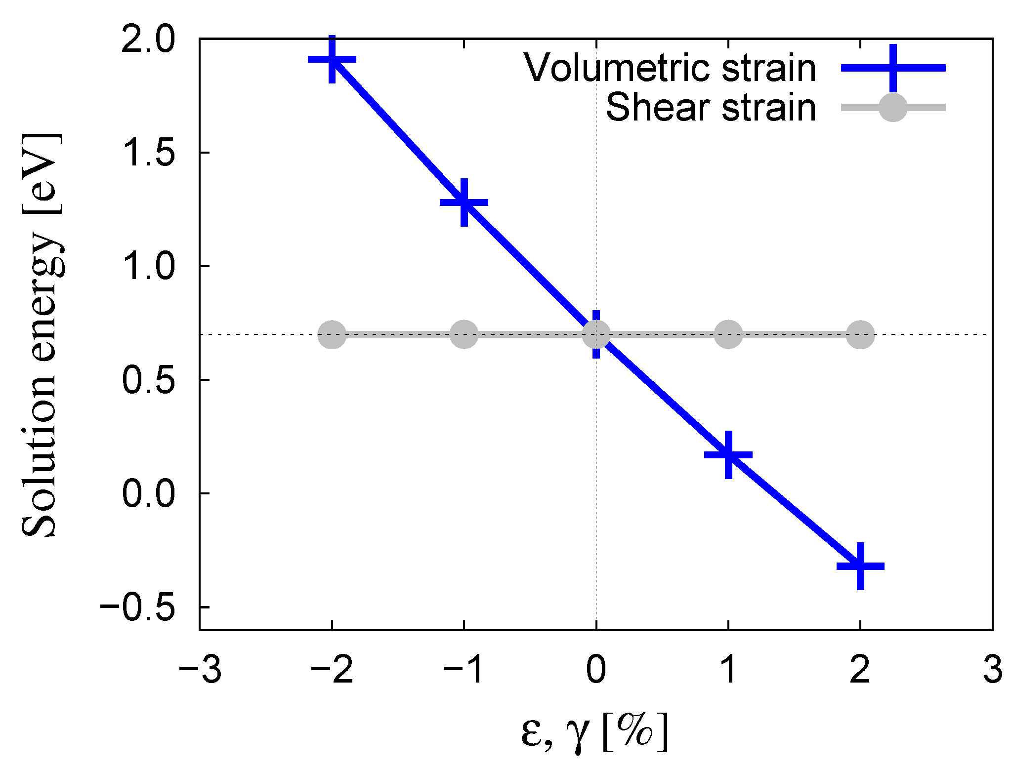
Next, we studied the dependence of H s with strain applied in the manner described in Section 2.1. The results are shown in Figure 4, clearly indicating a strong coupling to volumetric strain, but an almost negligible one to shear deformation. Assuming a linear dependence with ϵ , we find:
H s ( ϵ ) = 0.70 57.7 ϵ = 0.70 57.7 p 3 B W [ eV ]
where p = 1 / 3 Tr ( σ ) is the pressure and B W is the bulk modulus of pure W. For a value of B W = 308.5 GPa calculated using the same pseudopotential, we obtain the dependence of the heat of the solution with stress:
H s ( σ ) = 0.70 9.98 × 10 3 p = 0.70 3.33 × 10 3 ( σ x x + σ y y + σ z z ) [ eV ]
with p and the components of σ expressed in MPa.
We have also calculated the formation energy of an O atom at a vacant site and have obtained a value of 0.14 eV. This association with a vacancy results in a substitutional O atom, which, as earlier DFT calculations have shown for other interstitial solutes [43], effectively immobilizes it, thus changing the character of its contribution to the kinetic evolution of the system. This case will not be studied further, and in the following, we focus on interstitial oxygen migration pathways.

3.2. Oxygen Migration in Bulk Tungsten

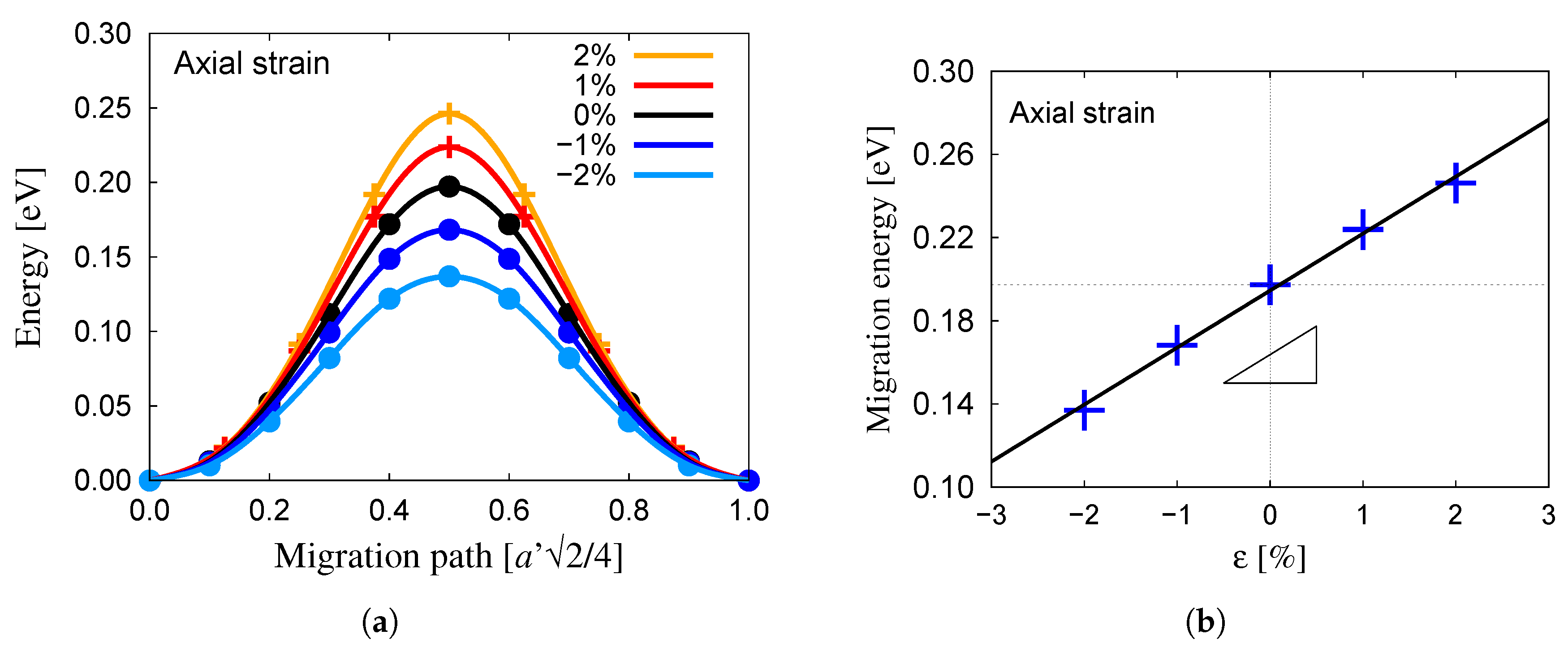
The migration barrier, E m , between two neighboring tetrahedral sites was evaluated using the NEB method (refer to Section 2). For zero strain, we found a value of 0.20 eV for the migration energy of O in W, in good agreement with the 0.17 eV obtained by Alkhamees et al. [41] and in contrast with values over 0.3 eV for octahedral→octahedral transitions by the same authors. This is also in concordance with both DFT and semi-empirical interatomic potential calculations of O migration in other bcc metals that consistently yielded larger values for the octahedral→octahedral jump [44,45,46]. Here, we expand on the calculations by Alkhamees et al. by studying the dependence of the migration barrier on hydrostatic and shear strain. Results for tensile and compressive strains are shown in Figure 5a. The results revealed a linear dependence of the migration energy barrier on hydrostatic strain, as shown in Figure 5b, with a proportionality constant of k hydro = 2.74 eV. This implies a constant activation volume, which for this transition can be calculated as:
Ω hydro = k hydro 3 B W
For the value of B W given above, Ω hydro = 0.47 Å 3 = 0.022 b 3 .
The dependence of the migration energy on shear strain is shown in Figure 6a. As mentioned above, shortened and lengthened paths (refer to Figure 1) are simply manifestations of the sign of the applied shear strain, and thus, we show all the calculations on the same plot.
In the case of shear, the activation volume is defined as:
Ω shear = k shear μ W
where, from the results in Figure 6b, k shear = 3.70 eV is the proportionality constant and μ W = 160.2 GPa is the shear modulus for the current pseudopotential. With this, an activation volume Ω shear = 3.98 Å 3 = 0.19 b 3 was obtained.
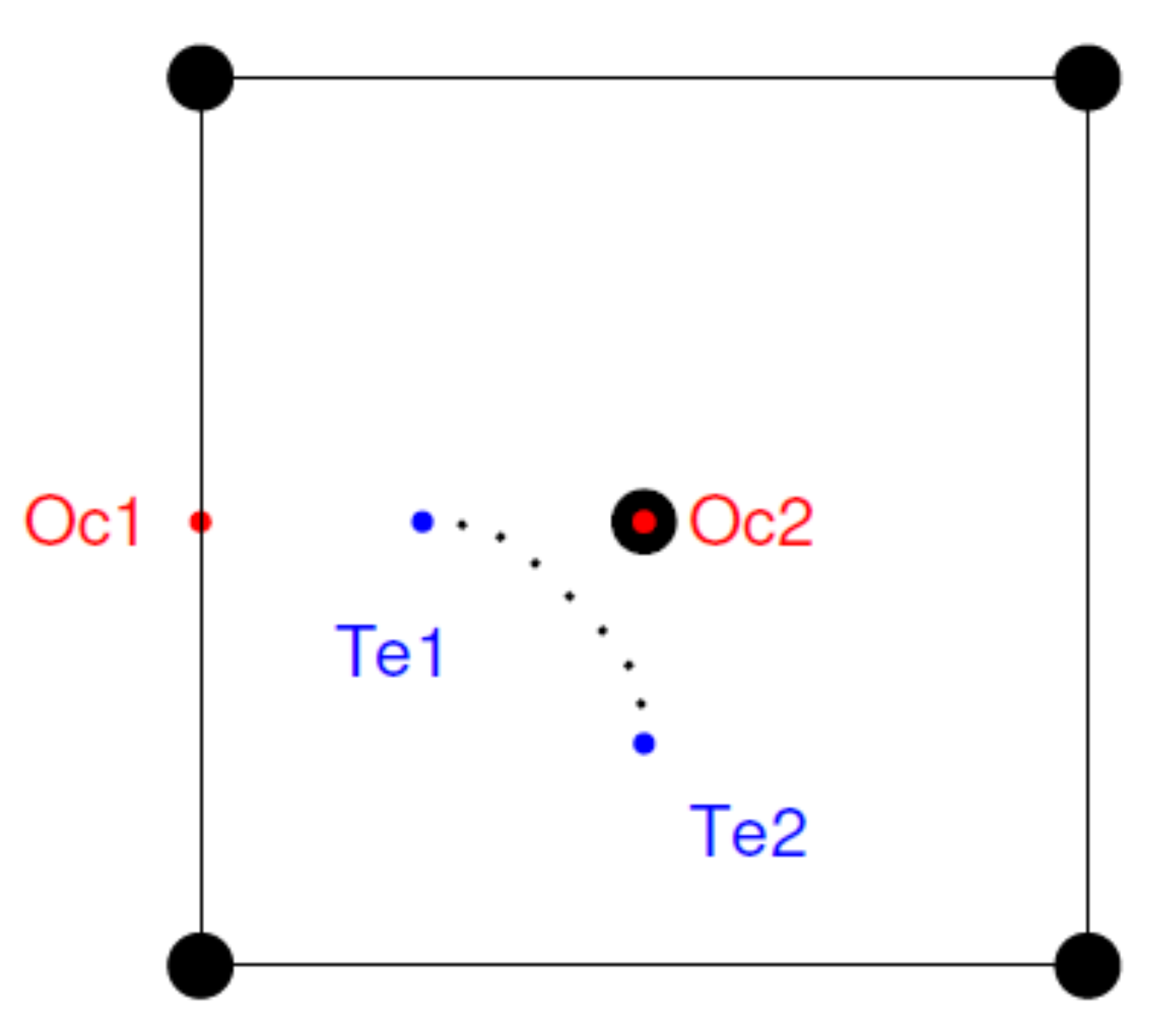
It is worth noting that although the reaction path in Figure 5a and Figure 6a is shown as projected along the rectilinear path joining two first-nearest neighbor (NN) tetrahedral sites, the actual trajectory is curved, as can be seen in Figure 7 for the unstrained case. The figure also shows the positions of two octahedral sites lying on the same ( 001 ) plane as the tetrahedral ones. It is important to point out that the while the octahedral position represents a local minimum for the O atom, the saddle point of the tetrahedral→tetrahedral transition is still a lower energy state than the octahedral one. This strengthens our assumption to discard octahedral→octahedral transitions as energetically less relevant than their tetrahedral→tetrahedral counterparts.

3.3. Screw Dislocation–Oxygen Interaction in Tungsten

The calculations carried out in the previous section allowed us to couple solute diffusion to the dislocation elastic fields. However, there also existed an inelastic interaction that took place when the solute atom was found close to the dislocation core. There, local nonlinear effects dominated over long-range elastic interactions, and it was therefore important to quantify them. Next, we calculated the interaction energies between oxygen atoms and screw dislocation cores in W using the geometries described in Section 2.2. The interaction energy is defined as:
E i = 1 2 E W O dislo E W dislo + E W bulk E W O bulk
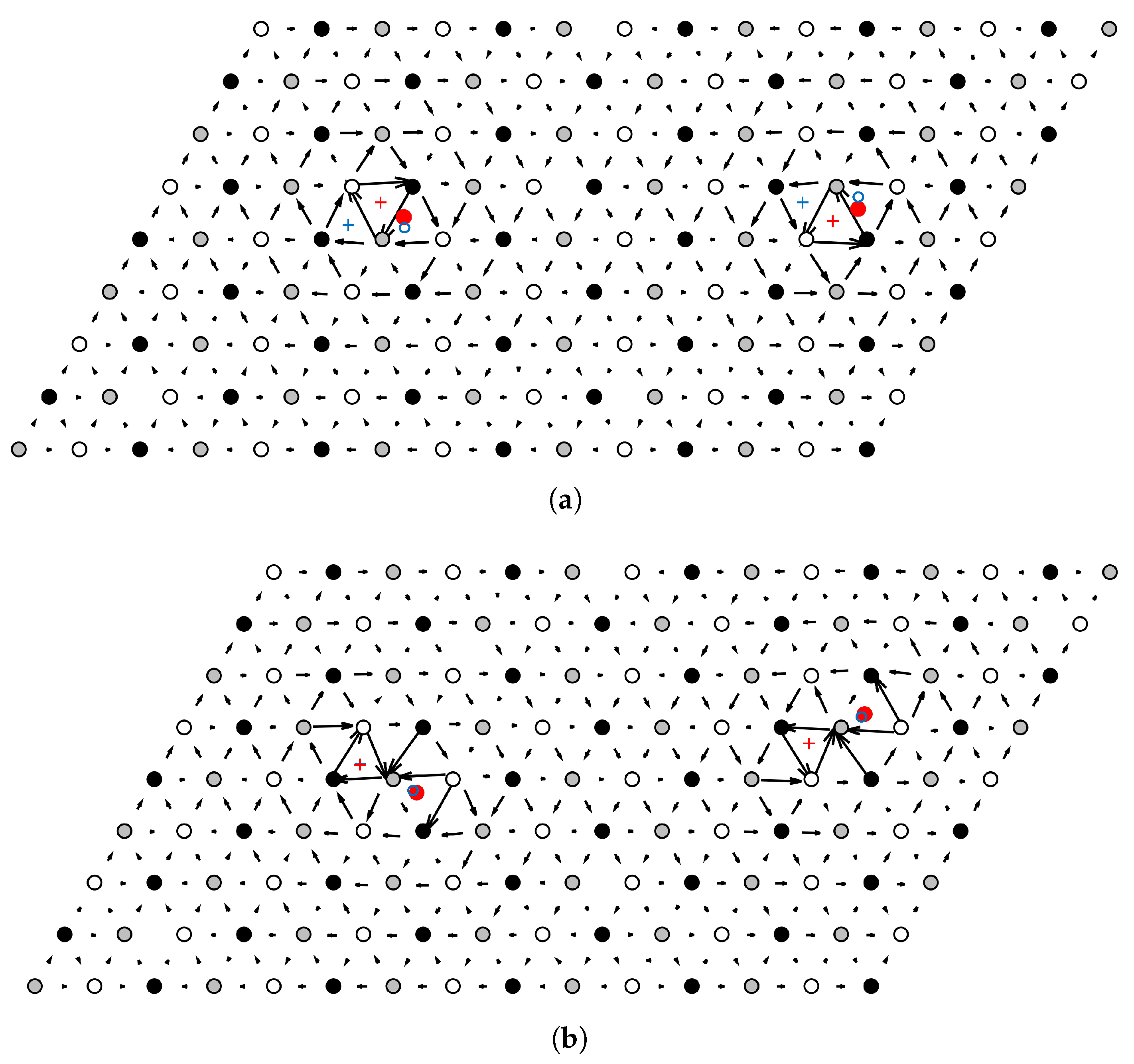
where E W O dislo and E W dislo are the energies of the dislocated cells with and without oxygen atoms, respectively, while E W O bulk and E W bulk are the energies of bulk W with and without O atoms. The 1 2 factor was used to account for the existence of two dislocations in the simulation cell with their corresponding oxygen atoms located at one of the six nearest tetrahedral sites to the dislocation core, as illustrated in Figure 2. Upon relaxation of the dislocation–O system in W, we found that only two stable final configurations were possible, depending on the initial position of the O atom, as illustrated in Figure 8. In the figure, the initial positions of the dislocation cores and the oxygen atoms are marked with blue crosses and blue circles, respectively, while their final relaxed positions are shown using red crosses and filled red dots. As for the reference configuration, differential displacement maps are used to identify the position of dislocation cores after relaxation.
Figure 8a shows the final configuration for the case where the O atom was originally introduced in the fourth NN position. One can see that upon relaxation, the dislocation core remained compact and symmetric, but its center had shifted towards the center of a neighboring downward-pointing triangle. This final dislocation core configuration corresponds to the so-called hard core configuration. Although the hard core configuration is known to be unstable in W and in most pure bcc metals [27,33], here, we found that the presence of O induced a reconstruction from the easy to the hard core configuration, similar to what has been reported for W-C in [24,27]. Because of this shift after relaxation, the relative position of the oxygen atom changed from fourth NN to second NN. Indeed, this was found to be the case for initial O atoms’ positions located in 1st, 2nd, 4th, and 6th NN tetrahedral sites, all with an interaction energy of 1.83 eV, which is indicative of a strong short-range interaction between the dislocation core and the oxygen atom.
A second possible stable configuration was obtained by relaxation of the dislocation–O system when the oxygen atom was inserted in the fifth NN tetrahedral site. In that case, both the dislocation cores and the O atoms remained in their initial positions, as illustrated in Figure 8b by the superposition of blue and red crosses and points that indicate the initial and final dislocation and O positions. The final core configuration was a distorted easy core, where the core was seen to spread between its original location and that of the O atom. A similar configuration has been reported for C interstitials in Ta [27]. Thus, the fifth NN tetrahedral site appeared to be a second stable possibility for the O atom in the vicinity of the dislocation core, with a corresponding interaction energy of 1.20 eV. Finally, when O was initially located in the third NN tetrahedral site, one of the dislocations of the dipole shifted to a hard core configuration with the O atom in the second NN position, and the other relaxed to the distorted easy core of the fifth NN configuration. Not surprisingly, its interaction energy was 1.52 eV, which was exactly the average of the energies of the second and fifth NN cases. Details for all six cases studied here, including a table showing all the corresponding energies, are given in Appendix A.
All the calculated energies were strongly negative, indicating a strong attraction between O atoms and the dislocation core. This is consistent with calculated elastic distortions of nearly 40 % in the atoms bounding the tetrahedral site around the solute atom (analyzed using local atomic displacements in OVITO [47]). The effect of the dislocation core is thus to accommodate these distortions caused by the O atom in its own displacement field, resulting in energetically very favorable configurations. For its part, it was seen that the deformation field due to the solute decayed very rapidly, such that it was almost zero at the second nearest neighbor positions from it.

4. Discussion

The present calculations are intended to provide quantitative support for mesoscale models of dislocation–solute coevolution, ultimately designed to explore the mechanisms behind serrated flow in bcc metals. As such, two types of interactions must be characterized, long and short range, of an elastic and inelastic nature, respectively. The former affects tetrahedral→tetrahedral oxygen atom migration under dislocation stress fields via an Arrhenius expression of the following type:
ν T , σ ( r ) = ν 0 exp Δ H a ( σ ( r ) ) k T
where ν 0 is an attempt frequency, Δ H a is the activation enthalpy for the diffusive jump, and k and T are Boltzmann’s constant and the absolute temperature, respectively. The activation enthalpy has several contributions:
Δ H a = E m + Δ H s W m
with:
E m = 0.20 eV Δ H s = H s ( σ ( r 2 ) ) H s ( σ ( r 1 ) ) W m = σ ( r 1 ) : Ω
where W m is the mechanical work and Ω is the activation volume tensor obtained in this work:
Ω = E m σ = Ω hydro Ω shear Ω shear Ω shear Ω hydro Ω shear Ω shear Ω shear Ω hydro = b 3 0.022 0.190 0.190 0.190 0.022 0.190 0.190 0.190 0.022
In Equation (5), σ represents the stress tensor defined at spatial points r 1 and r 2 representing the initial and final coordinates of the O atom transition, including all contributions, e.g., applied external stress, stresses from other dislocation segments, etc.
Our computed energies can also be put in the context of experimental measurements of oxygen diffusion in W. There were a number of studies looking at diffusion profiles of oxygen atoms in exposed W surfaces performed in the 1960s [48,49,50], and more recently in oxidized W specimens [51,52]. In general, activation energies between 1.0 and 2.0 eV were found in these tests. Our calculations (activation energy: H s + E m 0.9 eV) fell in the low end of these measurements. However, it is difficult to separate the effects due to surface roughness, impurity content, and other imponderables, from the experiments, while our calculations of course were free from these.
For its part, the inelastic effect occurs locally at the dislocation core, where linear elasticity is no longer suitable to capture the dislocation–oxygen interaction. A strong dislocation core–O atom attraction is found, as evidenced by interaction energies of up to 1.83 eV. While this is generally consistent with existing DFT studies of small interstitial impurities bound to screw dislocation cores in the literature [24,26,27,53,54], it must also be kept in mind that the present calculations were done for dislocation segments of length 1 b , and thus, a contribution to E i from periodic image O–O interactions cannot be discounted. By way of example, the interaction energies found in cells with thicknesses of 1 b and 2 b were 1.83 and 1.60 eV, respectively, for the case of a second NN stable O position. This suggests that a portion of the interaction energy calculated here is attributable to the stabilization effect created by the O–O bond. By way of example, we have calculated a relaxed bond length in the O 2 molecule of 1.23 Å, in good agreement with prior works [55,56]. While still smaller than the cell thickness of b = 2.75 Å, it appears to have a measurable impact on the final interaction energies. To ascertain this in more quantitative terms, we have also calculated the energy of a O–O pair separated by distances of 1 b and 2 b . The results are given in Table 1:
We recall that the energy of an isolated O atom is 1.59 eV (Section 3.1), which means that at a separation of 2 b , an O–O pair can be regarded as a pair of isolated atoms. This implies that computational cells with thicknesses of 2 b are sufficient to eliminate any O–O bonding from the simulations along the dislocation line. For separations of 1 b , an O–O pair has a binding energy of 0.56 eV. This is consistent with an excess energy of approximately 0.23 eV between the values of E i for 1 b and 2 b just discussed. In any case, these corrections do not affect our overall conclusions that a high attractive energy governs solute-dislocation core interactions, based on which it is reasonable to assume that the inelastic effect dominated over the elastic one as it relates to long-term evolution.
Additionally, when O atoms decorate the dislocation line in the manner created by the DFT calculations presented here, the core structure is seen to stabilize preferentially in a “hard” core configuration. Whether this is the case for longer dislocation segments (> 2 b ), i.e., for smaller O-atom linear densities, is not clear at present. On this point, it is worth noting that, although the hard core is in general a higher energy configuration for screw dislocations in bcc metals [32,33,35,57], several studies have shown that it can be stabilized by both substitutional [22,24] and interstitial [24,26] solute atoms, in agreement with the present study.
All the above effects must be included in simulations of the microstructural evolution to study the fundamental mechanisms behind interstitial solid solution softening/hardening or dynamic strain aging. We have some experience developing this type of model for substitutional alloys [58], which allowed us to push the length and timescale envelope to experimentally-meaningful levels. The coupling of the energetics obtained in this work and mesoscopic models of dislocation–solute evolution is the subject of an ongoing effort, which will be published in future studies.

5. Conclusions

  • We have conducted electronic structure calculations of the fundamental energetics of oxygen atoms in tungsten, including the heat of solution, migration energies, activation volumes, and interaction energy with screw dislocation cores.
  • Oxygen atoms are preferentially found in tetrahedral lattice sites, with solution energies of 0.70 eV. The substitutional heat of solution (an O atom associated with a vacant site) was found to be 0.14 eV.
  • The migration energy for the tetrahedral→tetrahedral transition in the bulk is 0.20 eV. This energy is modified by stress according to activation volumes of 0.02 b 3 and 0.19 b 3 for volumetric and shear deformations, respectively.
  • The interaction energy between a screw dislocation core and an O atom depends on the relative position of the oxygen, but it is found to be either 1.20 or 1.83 eV, depending on the final configuration. We find that this is due to the accommodation of the large local distortions induced by the O atom in the lattice, which is seen to lead to a core reconstruction from an easy core configuration to a hard core one when O atoms are present.
  • In most cases, once absorbed at a screw dislocation core, O atoms are seen to induce a dislocation core transformation from an easy core configuration to a hard core one.
  • These calculations will serve to parameterize mesoscale models of material deformation by dislocation slip.

Author Contributions

L.D. and J.M. designed the research. Y.Z. performed the DFT calculations. All authors discussed the data and participated in writing the manuscript.

Funding

The authors acknowledge support by the National Science Foundation under Grant DMR-1611342 and the U.S. Department of Energy’s Office of Fusion Energy Sciences, Project DE-SC0012774:0001. This work was also supported by the French State through the program “Investment in the future” operated by the National Research Agency (ANR) and referenced by ANR-11-LABX-0008-01 (LabEx DAMAS).

Acknowledgments

Computer time allocations at UCLA’s IDRE Hoffman2 supercomputer are acknowledged. Part of this research was performed using HPC resources from GENCI-CINES and TGCC from CEA under Grants 2016-097647, A0020910156, and A0040910156.

Conflicts of Interest

The authors declare no conflict of interest.

Appendix A. Compilation of DFT Results for Dislocation Core–Oxygen Atom Interaction Energy Calculations

Table A1 provides detailed information about the six dislocation–oxygen configurations studied in this work. We start our analysis with the structures shown in Figure 8a,b. The fourth NN and sixth NN configurations relax to a second NN configuration with two hard cores separated by the same distance as before relaxation and with the oxygen atoms also spaced the same amount ( 7.5 h 0 19.5 Å). Naturally, both of these configurations have identical interaction energies of 1.83 eV. Likewise, in the fifth NN case, the distances between oxygen atoms and between dislocation cores do not change, but a different final configuration is found (an extended easy core, cf. Figure 8b). In this case, the energy calculated with DFT is 1.20 eV.
The final configuration obtained for the third NN case is a combination of the two discussed above: one core adopts a hard-second NN configuration, while the second transforms into a fifth NN extended easy configuration. The resulting energy is exactly the average of 1.83 and 1.20 , i.e., 1.52 eV.
For the other cases, i.e., the first and second NN structures, the relaxed dislocation–O structure is a hard-second NN configuration achieved by way of core or solute shifts during relaxation. Due to the small simulation cell sizes, when such a shift occurs, an additional elastic energy is stored in the cell. For the first NN case, the distance between O atoms varies with relaxation, leading to a stored elastic energy of 0.07 eV (the O–O interaction in W was calculated with DFT). After the correction, we obtain an energy of 1.90 + 0.07 = 1.83 eV, consistent with the hard-second NN final configuration. Conversely, for the second NN case, core shifts lead to an increase of the separation distance between them, leading to an excess elastic energy of 0.02 eV (for details, see [33]). After correcting for this amount, we again get an energy of 1.81 0.02 = 1.83 eV, also consistent with a hard-second NN final configuration.
Table A1. Details of the calculations of the dislocation–O atom interaction energies for the six tetrahedral configurations considered in Figure 2. The first two columns specify the relative core–O atom positions before and after relaxation. The third and fourth columns indicate the distance between the two dislocation cores before and after relaxation in units of the periodicity of the Peierls potential, h 0 = a 0 6 / 3 (equal to the length of the triangles in Figure 2 and Figure 8). For example, 7.5 h 0 19.5  Å. Columns 5 and 6 give the distance between the oxygen atoms before and after relaxation, also in units of h 0 . The next column gives the structure of the dislocation cores obtained after relaxation (refer to Figure 8 for visual guidance). Finally, the last two columns give the uncorrected and corrected interaction energies in each case.
O-AtomDistance betweenDistance betweenFinal CoreUncorrectedCorrected
Location (NN)Cores ( h 0 )Oxygen Atoms ( h 0 )Configuration E i (eV) E i (eV)
initialfinalinitialfinalinitialfinal
127.57.57.56.5hard 1.90 1.83
227.58.57.57.5hard 1.81 1.83
32/57.57.57.57.5hard/ext.easy 1.52 1.52
427.57.57.57.5hard 1.83 1.83
557.57.57.57.5ext. easy 1.20 1.20
627.57.57.57.5hard 1.83 1.83

References

  1. Tietz, T.E.; Wilson, J.W. Behavior and Properties of Refractory Metals; Stanford University Press: Stanford, CA, USA, 1965. [Google Scholar]
  2. Davis, J.R. Alloying: Understanding the Basics; ASM International: Materials Park, OH, USA, 2001. [Google Scholar]
  3. Lassner, E.; Schubert, W.D. Tungsten alloys. In Tungsten; Springer: Berlin/Heidelberg, Germany, 1999; pp. 255–282. [Google Scholar]
  4. Lassner, E.; Schubert, W.D. Properties, Chemistry, Technology of the Element, Alloys, and Chemical Compounds; Vienna University of Technology: Vienna, Austria, 1999; pp. 124–125. [Google Scholar]
  5. Stephens, J.R. Effects of Interstitial Impurities on the Low-Temperature Tensile Properties of Tungsten; Technical Report; National Aeronautics and Space Administration Cleveland OH Lewis Research Center: Cleveland, OH, USA, 1964. [Google Scholar]
  6. Ulitchny, M.; Gibala, R. The effects of interstitial solute additions on the mechanical properties of niobium and tantalum single crystals. J. Less Common Met. 1973, 33, 105–116. [Google Scholar] [CrossRef]
  7. Stein, D.; Low, J., Jr. Effects of orientation and carbon on the mechanical properties of iron single crystals. Acta Metall. 1966, 14, 1183–1194. [Google Scholar] [CrossRef]
  8. Smialek, R.; Mitchell, T. Interstitial solution hardening in tantalum single crystals. Philos. Mag. 1970, 22, 1105–1127. [Google Scholar] [CrossRef]
  9. Baird, J. The effects of strain-ageing due to interstitial solutes on the mechanical properties of metals. Metall. Rev. 1971, 16, 1–18. [Google Scholar]
  10. Das, J.; Sankaranarayana, M.; Nandy, T. Serrated flow behavior in tungsten heavy alloy. Mater. Sci. Eng. A 2015, 646, 75–81. [Google Scholar] [CrossRef]
  11. Wells, A.F. Structural Inorganic Chemistry; Oxford University Press: Oxford, UK, 2012. [Google Scholar]
  12. Stephens, J.R. Effect of Oxygen on Mechanical Properties of Tungsten; Technical Report; National Aeronautics and Space Administration Cleveland OH Lewis Research Center: Cleveland, OH, USA, 1963. [Google Scholar]
  13. Cottrell, A.H.; Bilby, B. Dislocation theory of yielding and strain ageing of iron. Proc. Phys. Soc. Sect. A 1949, 62, 49. [Google Scholar] [CrossRef]
  14. Vitek, V.; Perrin, R.; Bowen, D. The core structure of 1/2 (111) screw dislocations in bcc crystals. Philos. Mag. 1970, 21, 1049–1073. [Google Scholar] [CrossRef]
  15. Clouet, E.; Garruchet, S.; Nguyen, H.; Perez, M.; Becquart, C.S. Dislocation interaction with C in α-Fe: A comparison between atomic simulations and elasticity theory. Acta Mater. 2008, 56, 3450–3460. [Google Scholar] [CrossRef]
  16. Trinkle, D.R.; Woodward, C. The chemistry of deformation: How solutes soften pure metals. Science 2005, 310, 1665–1667. [Google Scholar] [CrossRef]
  17. Medvedeva, N.; Gornostyrev, Y.N.; Freeman, A. Solid solution softening and hardening in the group-V and group-VI bcc transition metals alloys: First principles calculations and atomistic modeling. Phys. Rev. B Condens. Matter 2007, 76, 212104. [Google Scholar] [CrossRef]
  18. Romaner, L.; Ambrosch-Draxl, C.; Pippan, R. Effect of rhenium on the dislocation core structure in tungsten. Phys. Rev. Lett. 2010, 104, 195503. [Google Scholar] [CrossRef] [PubMed]
  19. Zhao, Y.; Lu, G. QM/MM study of dislocation—Hydrogen/helium interactions in α-Fe. Model. Simul. Mater. Sci. Eng. 2011, 19, 065004. [Google Scholar] [CrossRef]
  20. Li, H.; Wurster, S.; Motz, C.; Romaner, L.; Ambrosch-Draxl, C.; Pippan, R. Dislocation-core symmetry and slip planes in tungsten alloys: Ab initio calculations and microcantilever bending experiments. Acta Mater. 2012, 60, 748–758. [Google Scholar] [CrossRef]
  21. Itakura, M.; Kaburaki, H.; Yamaguchi, M.; Okita, T. The effect of hydrogen atoms on the screw dislocation mobility in bcc iron: A first-principles study. Acta Mater. 2013, 61, 6857–6867. [Google Scholar] [CrossRef]
  22. Samolyuk, G.D.; Osetsky, Y.; Stoller, R. The influence of transition metal solutes on the dislocation core structure and values of the Peierls stress and barrier in tungsten. J. Phys. Condens. Matter 2012, 25, 025403. [Google Scholar] [CrossRef] [PubMed] [Green Version]
  23. Romaner, L.; Razumovskiy, V.; Pippan, R. Core polarity of screw dislocations in Fe–Co alloys. Philos. Mag. Lett. 2014, 94, 334–341. [Google Scholar] [CrossRef]
  24. Ventelon, L.; Lüthi, B.; Clouet, E.; Proville, L.; Legrand, B.; Rodney, D.; Willaime, F. Dislocation core reconstruction induced by carbon segregation in bcc iron. Phys. Rev. B Condens. Matter 2015, 91, 220102. [Google Scholar] [CrossRef]
  25. Rodney, D.; Ventelon, L.; Clouet, E.; Pizzagalli, L.; Willaime, F. Ab initio modeling of dislocation core properties in metals and semiconductors. Acta Mater. 2017, 124, 633–659. [Google Scholar] [CrossRef]
  26. Lüthi, B.; Ventelon, L.; Rodney, D.; Willaime, F. Attractive interaction between interstitial solutes and screw dislocations in bcc iron from first principles. Comput. Mater. Sci. 2018, 148, 21–26. [Google Scholar] [CrossRef]
  27. Lüthi, B.; Ventelon, L.; Elsässer, C.; Rodney, D.; Willaime, F. First principles investigation of carbon-screw dislocation interactions in body-centered cubic metals. Model. Simul. Mater. Sci. Eng. 2017, 25, 084001. [Google Scholar] [CrossRef] [Green Version]
  28. Kresse, G.; Hafner, J. Ab initio molecular dynamics for liquid metals. Phys. Rev. B Condens. Matter 1993, 47, 558. [Google Scholar] [CrossRef] [PubMed]
  29. Blöchl, P.E. Projector augmented-wave method. Phys. Rev. B Condens. Matter 1994, 50, 17953–17979. [Google Scholar] [CrossRef] [PubMed] [Green Version]
  30. Kresse, G.; Joubert, D. From ultrasoft pseudopotentials to the projector augmented-wave method. Phys. Rev. B Condens. Matter 1999, 59, 1758–1775. [Google Scholar] [CrossRef]
  31. Clouet, E.; Ventelon, L.; Willaime, F. Dislocation core energies and core fields from first principles. Phys. Rev. Lett. 2009, 102, 055502. [Google Scholar] [CrossRef]
  32. Ventelon, L.; Willaime, F.; Clouet, E.; Rodney, D. Ab initio investigation of the Peierls potential of screw dislocations in bcc Fe and W. Acta Mater. 2013, 61, 3973–3985. [Google Scholar] [CrossRef]
  33. Dezerald, L.; Ventelon, L.; Clouet, E.; Denoual, C.; Rodney, D.; Willaime, F. Ab initio modeling of the two-dimensional energy landscape of screw dislocations in bcc transition metals. Phys. Rev. B Condens. Matter 2014, 89, 024104. [Google Scholar] [CrossRef]
  34. Ventelon, L.; Willaime, F. Generalized stacking-faults and screw-dislocation core-structure in bcc iron: A comparison between ab initio calculations and empirical potentials. Philos. Mag. 2010, 90, 1063–1074. [Google Scholar] [CrossRef]
  35. Itakura, M.; Kaburaki, H.; Yamaguchi, M. First-principles study on the mobility of screw dislocations in bcc iron. Acta Mater. 2012, 60, 3698–3710. [Google Scholar] [CrossRef]
  36. Hossain, M.; Marian, J. Stress-dependent solute energetics in W–Re alloys from first-principles calculations. Acta Mater. 2014, 80, 107–117. [Google Scholar] [CrossRef]
  37. Weinberger, C.R.; Tucker, G.J.; Foiles, S.M. Peierls potential of screw dislocations in bcc transition metals: Predictions from density functional theory. Phys. Rev. B Condens. Matter 2013, 87, 054114. [Google Scholar] [CrossRef]
  38. Duesbery, M.; Vitek, V.; Bowen, D.K. The effect of shear stress on the screw dislocation core structure in body-centred cubic lattices. Proc. R. Soc. Lond. A 1973, 332, 85–111. [Google Scholar] [CrossRef]
  39. Vitek, V. Structure of dislocation cores in metallic materials and its impact on their plastic behaviour. Prog. Mater. Sci. 1992, 36, 1–27. [Google Scholar] [CrossRef]
  40. Jiang, D.E.; Carter, E.A. Diffusion of interstitial hydrogen into and through bcc Fe from first principles. Phys. Rev. B 2004, 70, 064102. [Google Scholar] [CrossRef]
  41. Alkhamees, A.; Liu, Y.L.; Zhou, H.B.; Jin, S.; Zhang, Y.; Lu, G.H. First-principles investigation on dissolution and diffusion of oxygen in tungsten. J. Nucl. Mater. 2009, 393, 508–512. [Google Scholar] [CrossRef]
  42. Nguyen-Manh, D. Ab-Initio Modelling of Point Defect-Impurity Interaction in Tungsten and other BCC Transition Metals. Adv. Mater. Res. 2009, 59, 253–256. [Google Scholar] [CrossRef]
  43. Barouh, C.; Schuler, T.; Fu, C.C.; Jourdan, T. Predicting vacancy-mediated diffusion of interstitial solutes in α-Fe. Phys. Rev. B 2015, 92, 104102. [Google Scholar] [CrossRef]
  44. Shang, S.; Fang, H.; Wang, J.; Guo, C.; Wang, Y.; Jablonski, P.; Du, Y.; Liu, Z. Vacancy mechanism of oxygen diffusivity in bcc Fe: A first-principles study. Corros. Sci. 2014, 83, 94–102. [Google Scholar] [CrossRef]
  45. Frank, W.; Engell, H.; Seeger, A. Migration energy and solubility of oxygen in body centered cubic iron. Z. Metallkd. 1967, 58, 452–455. [Google Scholar]
  46. Li, R.; Zhang, P.; Li, X.; Zhang, C.; Zhao, J. First-principles study of the behavior of O, N and C impurities in vanadium solids. J. Nucl. Mater. 2013, 435, 71–76. [Google Scholar] [CrossRef]
  47. Stukowski, A. Visualization and analysis of atomistic simulation data with OVITO—The Open Visualization Tool. Model. Simul. Mater. Sci. Eng. 2009, 18, 015012. [Google Scholar] [CrossRef]
  48. Jacobs, A.J. Diffusion of Oxygen in Tungsten and some other Transition Metals. Nature 1963, 200, 1310. [Google Scholar] [CrossRef]
  49. Lee, C.H. Oxygen Diffusion in Tungsten. Nature 1964, 203, 1163. [Google Scholar] [CrossRef]
  50. Rapperport, E.; Nerses, V.; Smith, M. Diffusion in Refractory Metals; Technical Report; Defense Technical Information Center: Fort Belvoir, VA, USA, 1964. [Google Scholar]
  51. Butz, R.; Wagner, H. Diffusion of oxygen on tungsten (110). Surf. Sci. 1977, 63, 448–459. [Google Scholar] [CrossRef]
  52. Sikka, V.; Rosa, C. The oxidation kinetics of tungsten and the determination of oxygen diffusion coefficient in tungsten trioxide. Corros. Sci. 1980, 20, 1201–1219. [Google Scholar] [CrossRef]
  53. Lu, G.H.; Zhou, H.B.; Becquart, C.S. A review of modelling and simulation of hydrogen behaviour in tungsten at different scales. Nucl. Fusion 2014, 54, 086001. [Google Scholar] [CrossRef]
  54. Bakaev, A.; Terentyev, D.; Grigorev, P.; Posselt, M.; Zhurkin, E.E. Ab initio study of interaction of helium with edge and screw dislocations in tungsten. Nucl. Instrum. Methods Phys. Res. Sect. B Beam Interact. Mater. Atoms 2017, 393, 150–154. [Google Scholar] [CrossRef]
  55. Wang, G.; Ramesh, N.; Hsu, A.; Chu, D.; Chen, R. Density functional theory study of the adsorption of oxygen molecule on iron phthalocyanine and cobalt phthalocyanine. Mol. Simul. 2008, 34, 1051–1056. [Google Scholar] [CrossRef]
  56. Zhao, B.; Shang, C.; Qi, N.; Chen, Z.; Chen, Z. Stability of defects in monolayer MoS2 and their interaction with O2 molecule: A first-principles study. Appl. Surf. Sci. 2017, 412, 385–393. [Google Scholar] [CrossRef]
  57. Xu, W.; Moriarty, J. Atomistic simulation of ideal shear strength, point defects, and screw dislocations in bcc transition metals: Mo as a prototype. Phys. Rev. B 1996, 54, 6941. [Google Scholar] [CrossRef]
  58. Zhao, Y.; Marian, J. Direct prediction of the solute softening-to-hardening transition in W–Re alloys using stochastic simulations of screw dislocation motion. Modell. Simul. Mater. Sci. Eng. 2018, 26, 045002. [Google Scholar] [CrossRef] [Green Version]
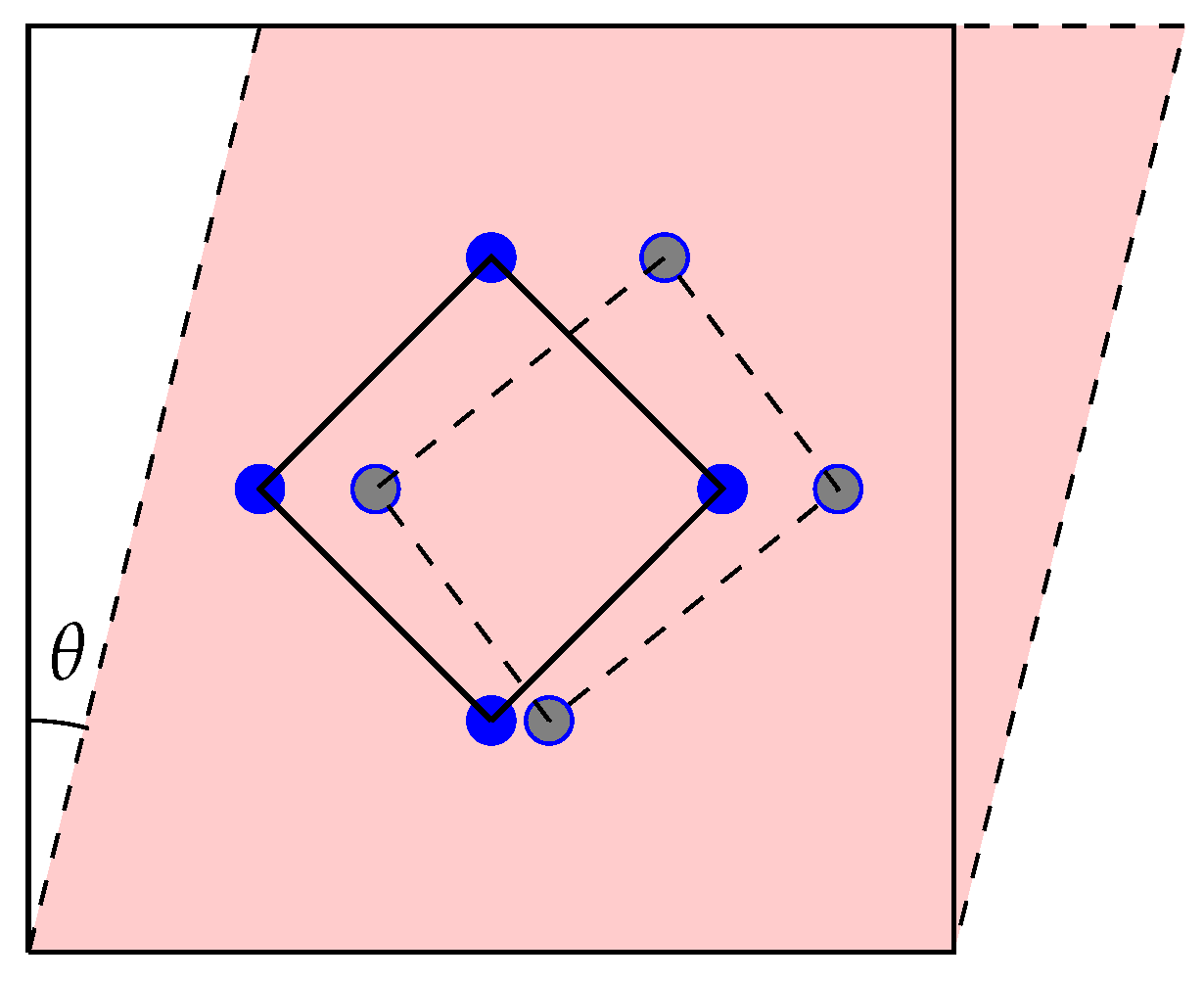
Figure 1. Illustration of the distortion of tetrahedral→tetrahedral paths under shear deformation. The undeformed path becomes stretched along two directions and compressed along the other two. θ represents the shear angle (refer to Section 2).
Metals 09 00252 g001
Figure 2. Location of the six nearest tetrahedral sites (blue points) to the geometric center of a screw dislocation core (green cross) before the relaxation of the dislocation–O system with DFT. The dislocation is in an easy core configuration. The arrows represent the amplitude of differential atomic displacements along the 111 direction (normal to the image) induced by the presence of the dislocation. The atoms are color-coded according to their relative position along the [ 111 ] direction (off-plane): white for z = 0 , grey for z = b / 3 and black for z = 2 b / 3 .
Metals 09 00252 g002
Figure 3. Elementary bcc lattice cell showing octahedral and tetrahedral interstitial sites. As a guide to the eye, the figures show a shaded octahedron and tetrahedron with the interstitial site highlighted in their respective centers. In principle, transitions may occur between any two nearest neighbor interstitial sites.
Metals 09 00252 g003
Figure 4. Variation of the heat of solution of tetrahedral O as a function of volumetric, ε , and shear, γ , strain.
Metals 09 00252 g004
Figure 5. (a) Tetrahedral→tetrahedral oxygen migration energy path in bulk W calculated with DFT between two neighboring tetrahedral sites under hydrostatic strain. a is defined in Equation (1). (b) Migration energy barrier under uniform axial strain. The black line represents a least-squares linear fit, from whose slope (black triangle) the activation volume can be calculated.
Metals 09 00252 g005
Figure 6. (a) Tetrahedral→tetrahedral oxygen migration energy path in bulk W calculated with DFT between two neighboring tetrahedral sites under shear strain. (b) Migration energy barrier under shear strain. The black line represents a least-squares linear fit, from whose slope (black triangle) the activation volume can be calculated.
Metals 09 00252 g006
Figure 7. Relaxed migration path of an oxygen atom between two tetrahedral sites on a ( 001 ) plane under zero strain showing two neighboring octahedral sites for reference. The trajectory follows a curved path arched towards the closest octahedral site.
Metals 09 00252 g007
Figure 8. Stable relaxed configurations of the dislocation core/O-atom system. All other initial configurations (see Figure 2) relax to one of these. The cross marks the location of the dislocation core (blue: initial, red: final), while the blue and red dots mark the initial and final position of the O atoms, respectively. (a) The initial configuration starts with the oxygen atom in a fourth NN tetrahedral position. After relaxation, the core shifts to a hard core configuration, and the oxygen atoms shifts to a second NN position. The dislocation maintains its compact core structure after relaxation. The calculated interaction energy is 1.83 eV. (b) The initial configuration starts with the oxygen atom in a fifth NN tetrahedral position. After relaxation, neither the dislocation nor the O atom have shifted; however, the dislocation core becomes asymmetric. The calculated interaction energy is 1.20 eV.
Metals 09 00252 g008
Table 1. Bond lengths and total and half energies of O–O complexes in the vacuum. The top row corresponds to the stable O 2 molecule.
d O O ( Å) E O O (eV) 1 2 E O O (eV)
1.23 (O 2 ) 9.84 4.92
2.76 ( 1 b ) 3.74 1.87
5.52 ( 2 b ) 3.18 1.59