Joining of Aluminium Alloy Sheets to Aluminium Alloy Foam Using Metal Glasses
by
 ,
,
Muhammad Kashif Bangash
1,* ,
,
Graziano Ubertalli
1,
Davide Di Saverio
1,
Monica Ferraris
1 and
Niu Jitai
2 1
Department of Applied Science and Technology, Politecnico di Torino, Corso Duca degli Abruzzi, 24, 10129 Torino, Italy
2
School of Material Science and Engineering, Harbin Institute of Technology, Harbin 150001, China
*
Author to whom correspondence should be addressed.
Metals 2018, 8(8), 614; https://doi.org/10.3390/met8080614
Submission received: 3 July 2018
/
Revised: 30 July 2018
/
Accepted: 3 August 2018
/
Published: 6 August 2018
(This article belongs to the Special Issue Diffusion Bonding and Brazing of Advanced Materials)
Abstract
:Aluminium alloy foam is a lightweight material with high energy absorption properties and can potentially replace bulk Al-components. The aim of this work is to develop a brazing technique to join aluminium facing sheets to aluminium alloy foam to obtain aluminium foam sandwich panels for applications where high service temperature is a requirement. Al-6016 alloy sheets were brazed to aluminium alloy foam using two aluminium based (Al-Cu-Mg and Al-Si-Mg-Ti) metal glasses at 560 °C–590 °C in an argon atmosphere. Microstructure and microhardness profiles of the aluminium alloy sheet/aluminium alloy foam brazed joints were analysed using a microhardness tester and scanning electron microscope equipped with electron dispersion spectroscopy. A three-point bending test was conducted to study the flexural behaviour of the aluminium foam sandwich composite panels.
1. Introduction
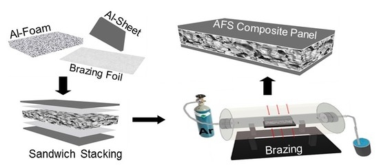
Aluminium foam sandwich (AFS) panels, compared to bulk Al components of the same mass, are multifunctional, stiffer, and offer excellent corrosion resistance for many industrial applications including automotive, marine, aerospace, construction and railway [1,2]. AFS are made of thin rigid Al-alloy sheets (facing sheets) joined with a porous, lightweight Al-alloy foam (core). The outer sheets bear the tensile loads while the foam core contributes to absorbing static and dynamic impact energies [3]. Most recently Al-alloy metal foam parts were developed by the Technical University Berlin and Pohltec Metalfoam used in the prototype of an ultra-light electric vehicle recently developed in a European project [4].
Different applications of AFS have led to the development of various Al-alloy foam manufacturing and Al-alloy foam/Al-alloy sheet joining techniques, such as casting, brazing [5], and soldering [6] techniques. The current practice of AFS components joining using adhesives and solders restrict the applications of AFS composite panels in the range 220 °C–380 °C. The fabrication of AFS composite panels for higher service temperatures requires alternative joining methods and materials, which is focused in this study. The AFS obtained by brazing the facing sheets to the core can meet the heat resistance, stability at elevated temperatures and non-flammability requirements, which are not satisfied when the facing sheets are joined to the core by an adhesive or a solder alloy [7].
In general, a configuration comprising two massive face sheets or a hollow metal piece with a foamable material in the core layer is adapted to produce AFS bonded by the foaming technique. The central foamable aluminium-based material melts at a lower temperature with respect to face sheets. This difference in the melting temperatures is exploited to produce AFS composite panels by expanding the foamable material and prevent the face sheets from melting [2].
The melting temperature of the most common foamable precursor alloy (AlSi6Cu4 or AlSi6Cu6) is 524 °C which can be coupled with 1xxx, 3xxx, 5xxx, and 6xxx series Al-alloys face sheets to produce AFS panels by foaming technique [7]. The solubility of Mg, Cu, and Ti in solid aluminium, by weight, is 17.4% at 460 °C, 5.65% at 548 °C, and 1.3% at 665 °C, respectively [8], and their addition suppresses the melting point of the aluminium-based alloy and/or precursor. The addition of Ti traces to the Al-Si-Mg system is suggested to be further beneficial as the diffusion of Ti atoms towards Al is more pronounced than Al atoms towards Ti [9]. The advantage of replacing Cu with Mg is the improved corrosion resistance [4]. The disadvantages of bonding Al-alloy sheets to Al-alloy foam by the foaming process include the restricted set of possible alloy combinations for the core and face sheet due to the necessity to coordinate the melting temperatures of the core and the sheet, the need to use expensive metal powders, and the high number of processing steps [7].
Soldering/brazing is a well-known joining method, where a relatively low melting filler material is used to bond two similar or dissimilar materials by heating. The success of soldering/brazing process depends on careful optimization of the fundamental parameters, such as time, temperature, and the provided atmosphere (inert/vacuum). The brazing cycle itself can be considered a thermal treatment to achieve a precipitation hardening effect whenever the adopted cooling rates are sufficiently fast [10]. The pore structure of aluminium alloy foam and Al-sheet collapses at higher temperatures and also densifies the AFS due to difficulty in the foaming of the weld pool along the joint.
Huang et al. [11] and Wan et al. [12] proposed fluxless soldering options, with and without mechanical vibration assistance, and used Zn-Al-Cu-Mg-Mn-Ag alloy as the joining material. Al-Si alloys have been used as filler materials, for AFS with a 6xxx series Al face sheet, which contain 7–12 wt % silicon as a melting point depressant [13]. The addition of Mg, Si, and Cu to Al, if added up to their respective solubility limits, increases the mechanical strength of the joint [14]. Most recently, Ubertalli et al. [15] reported a soldering method using pure Zn or Zn + 2%Al as joining materials in an argon atmosphere as a simple, reliable, and less time-consuming alternative to achieve a porous joint. In the recent past, Nannan et al. [5] successfully experimented with higher temperature brazing of Al-alloy foam to itself in vacuum at 590 °C using a multilayer Al12Si1.8Mg alloy as the brazing filler metal, however, the brazing of Al-alloy sheets to Al-alloy foam for applications where the service temperature is above 400 °C is still required.
In this study, AFS panels were produced by using two Al-based (Al-Cu-Mg and Al-Si-Mg-Ti) metal glasses as a brazing material: the choice was dictated by their composition, which is similar to the Al-alloy foam precursor [8,16,17]. The Al-alloy sheet/Al-alloy foam joints were characterized by microstructural observation and microhardness analysis through the thickness. Three-point bending tests were conducted to evaluate the flexural behaviour and to determine the bending strength of the produced AFS panel. A comparison of different joining materials for AFS, the effect of high-temperature brazing on Al-6016 sheets, and the optimization of the joining processes are discussed.
2. Materials and Methods
Aluminium alloy (Al-6016) sheets were brazed to a pre-manufactured Al-alloy foam plate to obtain aluminium foam sandwich (AFS) panels using metal glasses as a joining material. Al-6016 (Al 98.4% + Si 1.2% + Mg 0.4%), 1.2 mm thick plate (density 2.7 g/cm3), one of the most common Al alloy used in automobile industry, was selected as the facing sheet material for AFS. A lightweight (1/10 aluminium, 1/30 iron, 1/4 wood), closed cell, non-flammable and recyclable (eco-friendly) Al-alloy foam, (Alporas Type, Composition: Al1.5Ca + 1.5 Ti wt % [16]), 9 mm thick, average density 0.24 g/cm3 (measured dividing mass by volume), produced by Foamtech, Seoul, South Korea and supplied by Vaber, Torino, Italy, was used as a core material.
The production of Alporas foams starts with the addition of 1.5 wt % calcium metal into the molten aluminium to increase the viscosity by the formation of calcium oxides. Titanium hydride (TiH2) is added (typically 1.6 wt %) as a blowing agent. The melt starts to expand slowly and gradually fills the foaming vessel at constant pressure. Upon cooling the liquid foam turns into a solid Al foam [18,19].
The macrographs of cross-sectional surfaces of a set of twenty-five Al-alloy foam samples of dimension 9 mm × 20 mm were analysed, using the free digital image analysis software, Image-J (Fiji) [20], to determine a statistically relevant average pore size and pore distribution in the cross-section of Al-alloy foam used in this study. The Al-alloy foam surface is characterized by cells of variable size and their walls and plateau borders represent the surface area available for joining. Lower average pore size results in a higher density of foam and also in an increase of available area for joining.
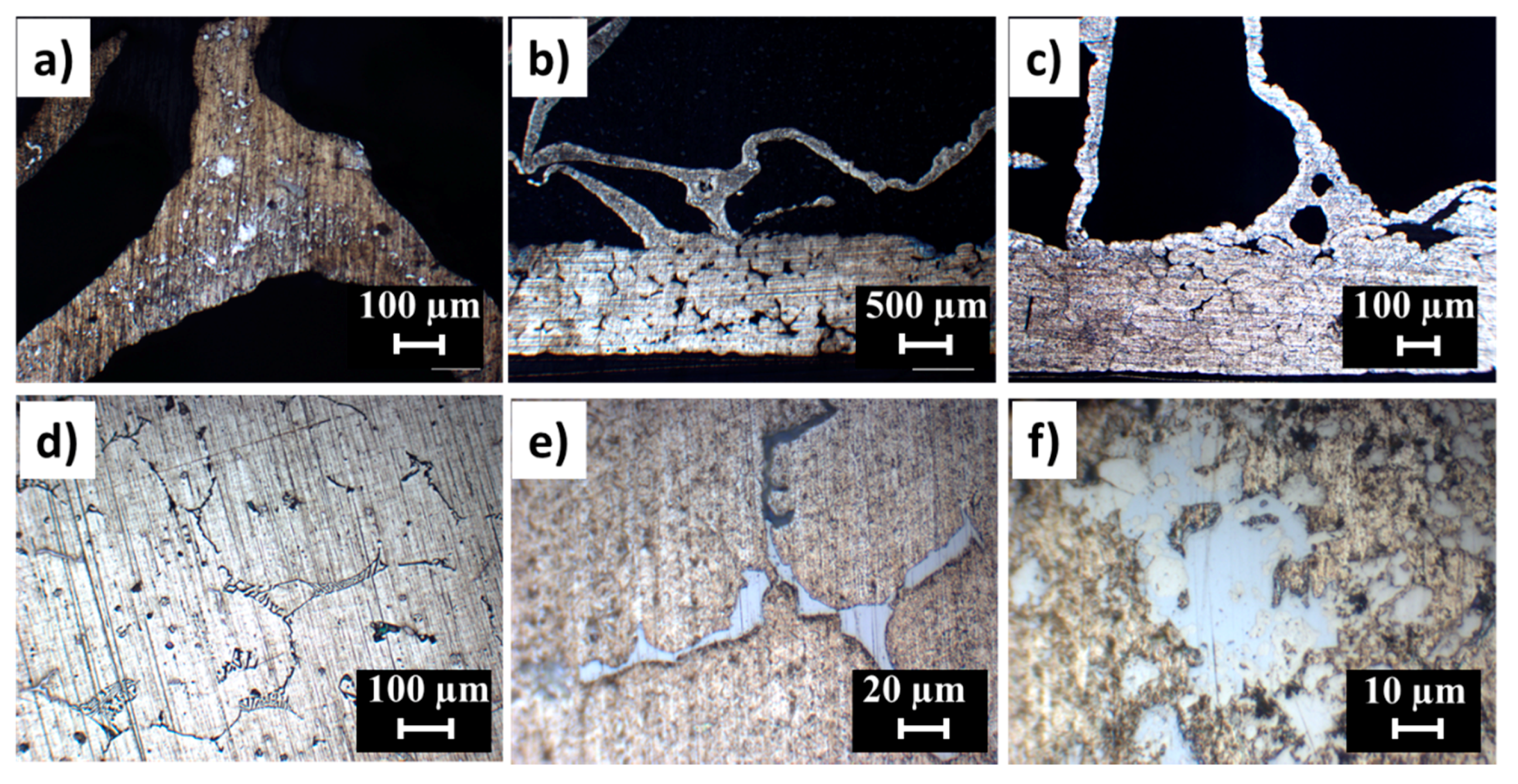
Figure 1a represents the as-received closed cell Al-alloy foam surface, Figure 1b the prepared samples for macro-image and Figure 1c the digitally-elaborated image of the Al-alloy foam surface. The Image J gives 2D results for the equivalent pore size as most of the cells were not cut through their maximal diameter due to their non-homogenous distribution in the foam structure. Figure 1d shows the pores distribution on the surface of 25 Al-alloy foam samples that fit into a bell-shaped curve; the equivalent pore diameter calculated was 5.2 mm ± 1.5 mm. The pore cell walls and the plateau borders, which constitute the potential joining area, accounts for around 12.8% of the total Al-alloy foam plate surface area.
The brazing materials were two Al-based amorphous brazing alloys (metal glasses), Al-14Cu-4Mg alloy (0.06 mm thick foil) and Al-7Si-2Mg-1Ti (0.08 mm thick foil) produced by the rapid planar flow casting method [21]. Al-6 flux supplied by Stella Srl, Albizzate, Italy was used to improve the joining surface wettability and to prevent Al-oxide inclusions in the joints.
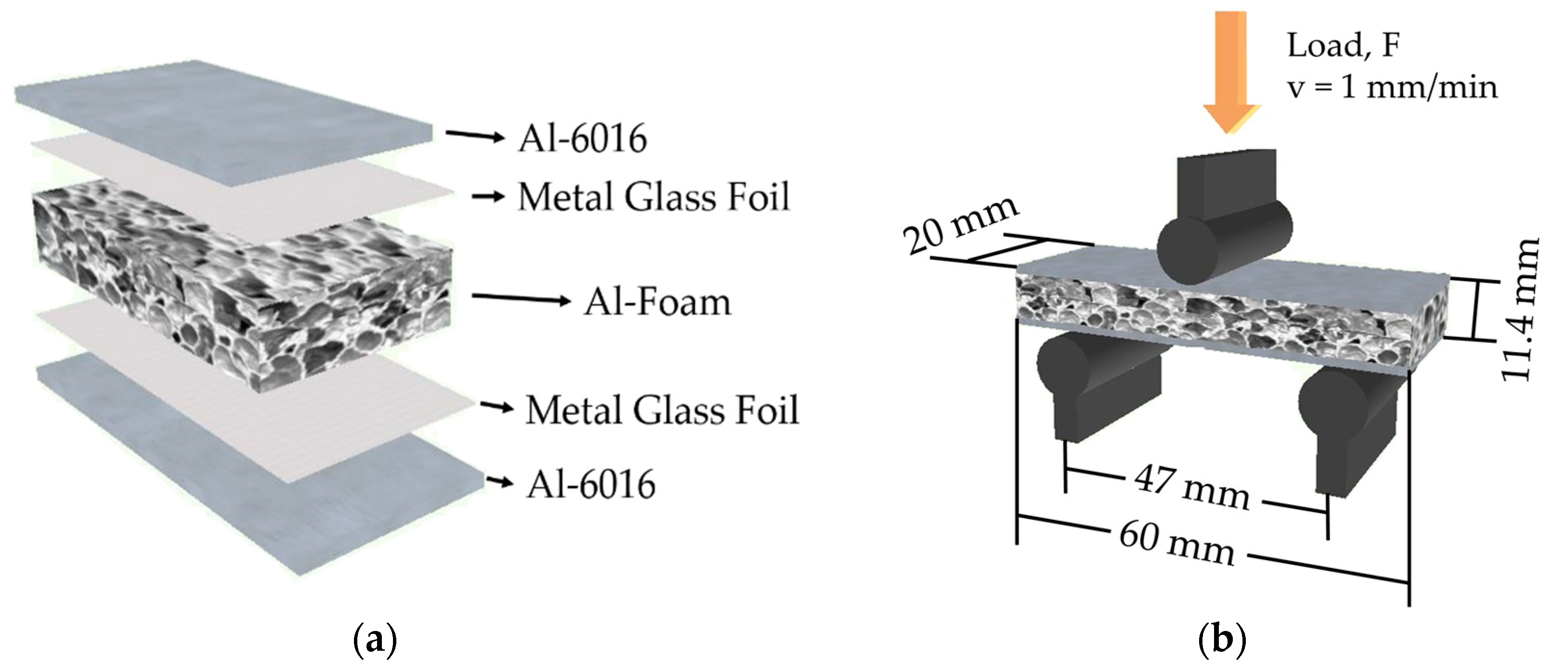
The joining faces of Al-alloy sheet and Al-alloy foam were first abraded with 120–360 grid SiC emery paper to remove the surface oxide layer and then cleaned with alcohol in an ultrasonic bath at 60 °C for 10 min. Subsequently, the Al-alloy foam surface (Figure 1a) was activated by using 12% nitric acid solution for 30 min as is suggested by Qingxian et al. [22]. The stacking configuration adopted for AFS in the current study is shown in Figure 2a.
The brazing experiment was carried out in a tube furnace (Carbolite Gero®, Hope Valley, UK) at 560–590 °C for 10–15 min at a heating rate of 600 °C/h–1000 °C/h, and then cooled (100 °C/h cooling rate) to room temperature, in an argon flow. Several sets of time/temperature pairs were tried to achieve good joints. The optimized conditions to join Al-alloy foam to Al-6016 facing sheets were: brazing for 10 min at 560 °C when three foils Al-Cu-Mg amorphous alloy were used as brazing material and brazing for 15 min at 590 °C when three layers of Al-Si-Mg-Ti were used as the brazing material. During the joining process optimization, a lower brazing temperature was preferred with respect to a shorter time because at higher temperatures the Al-alloy sheets were severely affected. The average density of AFS produced with Al-Cu-Mg and Al-Si-Mg-Ti amorphous joining materials was observed at 0.89 ± 0.01 g/cm3 and 0.82 ± 0.01 g/cm3, respectively.
At the optimized brazing conditions, six AFS composite specimens were produced (three specimens with each of the brazing materials) for mechanical characterization and metallographic cross-section analysis. The AFS cross-section morphology was analysed using an optical microscope (OM) and scanning electron microscope (SEM) equipped with electron dispersion spectroscopy (EDS).
The microhardness of the base components (Al-alloy foam and Al-alloy sheet) and the Al-alloy foam/Al-alloy sheet joining interface was determined using a microhardness tester equipped with a VM4-USB camera and measuring software VMS-VMH software (Leitz–Wetzlar, Wetzlar, Germany). The cross-sections of AFS brazed specimens were cut off the sandwich AFS specimens and the open foam pores were completely filled with resin to avoid the deterioration and/or buckling of the foam cell walls during grinding, polishing, and subsequent microhardness testing. In the case of Al-alloy foam, microhardness was preferably measured in the vertices or in the thicker cell walls. Vickers hardness values were obtained using a load of 10 g for 30 s at various positions in the Al-alloy foam, Al-alloy sheet and at the joining interface of the AFS before and after the brazing process.
The brazed AFS specimens produced for the flexural test were 60 mm long, 20 mm wide with a total thickness of around 11.4 mm. In order to analyse the effect of brazing conditions on the properties of base materials, three specimens of each base material (Al-alloy sheet and Al-alloy foam) were also subjected to three-point bending test before and after the similar thermal treatment adopted in this study. All three-point bending tests were conducted using a universal testing machine (MTS-810 at DISAT, Politecnico di Torino) at room temperature (25 °C) and 65% relative humidity. Figure 2b presents the three-point bending test assembly configuration and the parameters adopted during the test. When 10 mm cross-head displacement was reached, loading was stopped. The collapse behaviour of Al-alloy foam and the failure modes of AFS components were determined by analysing digital images and the video recorded for each test event.
3. Results and Discussion
3.1. Al-Alloy Sheet/Al-Alloy Foam Joint Microstructure Analysis
Transverse metallographic sections of the produced AFS components were obtained and observed using OM, SEM, and EDS.
Figure 3a,b micrographs of polished cross-sections of the two categories of produced AFS show apparently good connections at the interface between the joining substrates (Al-alloy sheet and Al-alloy foam) after the brazing process. As the Al-alloy foam is non-homogenous and the pores size and distribution vary, therefore, Al-alloy sheet/Al-alloy foam joint is not continuous. The amount of Al-alloy foam/Al-alloy sheet connecting points depends on the number of cell-walls and the plateau border per unit area in the foam surface as discussed in Section 2.
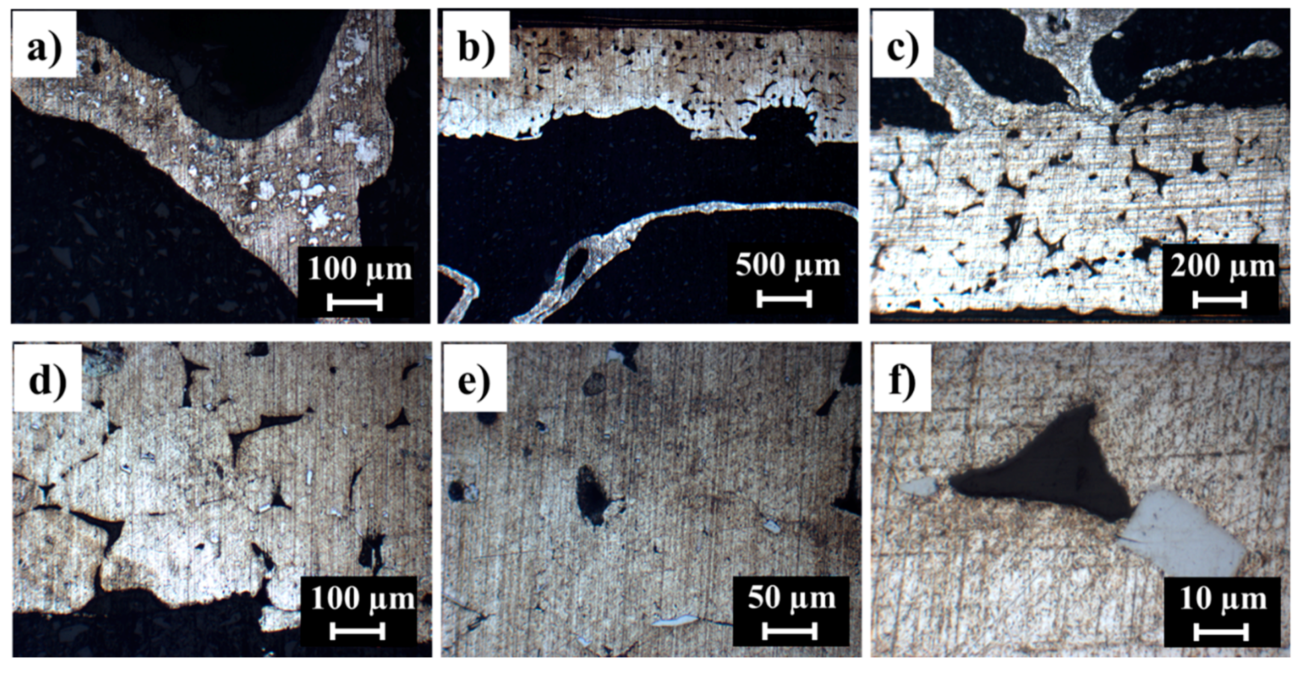
Figure 4 presents the micrographs of the AFS specimen brazed with Al-Cu-Mg brazing alloy at higher magnification. Al-alloy foams are relatively stable at higher temperatures (melting T = 660 °C) because the metal matrix contains finely dispersed oxide particles originating from the surfaces of the powder particles in the foamable precursor material [23]. However, after the brazing process, the precipitation of finely dispersed secondary particles was observed, Figure 4a, throughout the Al-alloy foam wall structure. In a similar investigation [24], the formation of Mg2Si and AlFeMnSi phases in the microstructure of heat treated Al-alloy foam (6xxx series, at 503 °C for 90–100 min) were observed. The microstructure analysis of the joining interface revealed that Al-Cu-Mg alloy melted and reacted with the joining substrates when the temperature reached 560 °C. At this brazing temperature, the Al-alloy sheet partially melted along some grain boundaries and, after the solidification, a porous microstructure appeared due to shrinkage of the melted zones, Figure 4c,d. It happened due to the diffusion of molten Al-Cu-Mg glass alloy into the Al-alloy sheet which suppressed the melting point of Al-alloy sheet and resulted in its partial melting, as can be seen in Figure 4b,c. Similar observations are reported by Ubertalli et al. [15] where Zn based joining material suppressed the melting point of the Al-alloy (6016) sheet during the soldering of Al-alloy foam (Alporas) to Al-alloy (6016) sheet. Figure 4e,f evidences the formation of secondary phase particles’ precipitation in the microstructure of the Al-alloy sheet.
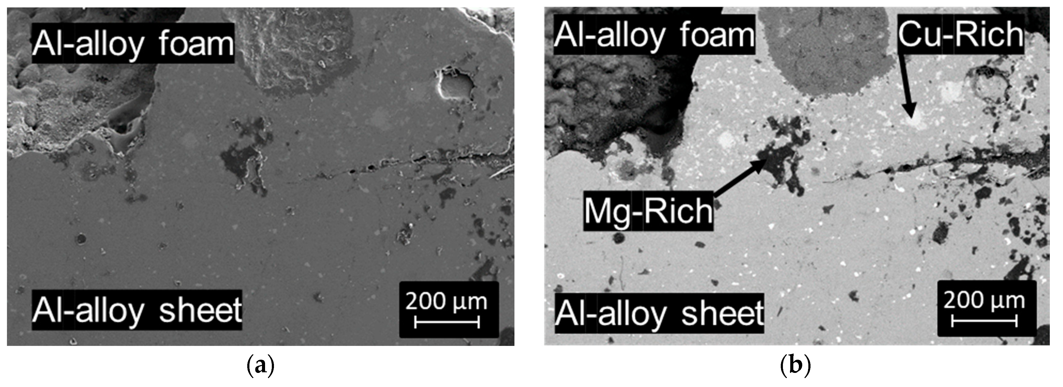
SEM and back-scattered observation were conducted to show the type of secondary phase compounds dispersed in the microstructure, Figure 5. Figure 5a shows a sound connecting point between the Al-alloy sheet and Al-alloy foam where the brazing alloy is diffused into the joining substrates. The spot EDS analysis, conducted in the arrows positions confirmed the presence of Cu-rich and Mg-rich, Figure 5b, containing compounds, along with traces of oxygen, which evidences the possible formation of oxides.
At the brazing temperature (560 °C), the brazing amorphous alloy with 14% Cu produces a liquid phase in equilibrium with Al alpha (α) solid phase that solves around 5.6% of Cu at the eutectic temperature and rejects the excess Cu as coarse theta (θ) particles. During cooling, the solidification of the liquid produces eutectic microstructure containing precipitates of θ particles. Below the eutectic temperature, the amount of Cu in α phase decreases and this can both induce a growth of the primary formed θ particles and/or the formation of new finer secondary θ phase particles. At room temperature, the α phase contains less than 0.5% Cu while the inter-metallic compound, CuAl2 (θ) contains 52% Cu, Figure 5b (Cu-rich phase). The θ particles have a moderate strengthening effect on the alloy properties [25]. The contribution of Mg as an alloying element is the formation of stable intermetallic compounds β-Al3Mg2 and γ-Al12Mg17 [26,27], Figure 5b (Mg-rich phase). Both of these intermetallic compounds (Cu-rich and Mg-rich) are brittle [28] which may influence the mechanical properties of the resultant alloy.
In fact, the solid-state diffusion is a time-temperature dependent phenomenon and it becomes more rapid at a temperature above 425 °C when Mg diffuses very quickly and forms oxides at higher melting temperature [29] at early stages of the brazing process. Orman et al. [30] reported that Mg favours the formations of oxides and suggested that oxide free joint can be achieved if Mg content is restricted to or below 0.3% along with the use of standard brazing flux. Higher amounts of Mg deteriorate the brazing joint quality due to the formation of oxides, having higher melting points, which reduces the fluidity of molten cladding alloy. The lower brazing alloys fluidity affects the resultant joint strength, which has a direct relation to the extent of the wetted surface area. Moller and Grann et al. [31] suggests that, at a temperature above 570 °C, Mg vaporizes and produces a “mag burst” which works as an oxygen getter. This loss of filler metal caused by vaporization reduces the quantity of joining material and compromises the joint strength.
For this reason, the second selected amorphous brazing alloy as a joining material used was with a lower Mg content, to avoid the higher amount of oxide formation while the addition of Si and Ti maintains the strength properties of the joint.
The metallographic analysis of the AFS cross-section, where Al-Si-Mg-Ti was used as a brazing alloy, are shown in Figure 6. Formation of relatively smaller secondary phase particles with agglomerated, but smaller, second phase particles was observed in the morphology of Al-alloy foam, Figure 6a, as compared to those observed in Figure 4a. Very likely, a higher brazing temperature and longer brazing time triggered the grain growth and allowed the recrystallization of secondary phase particles. Figure 6b,c shows that most of the brazing material reacted with the joining substrates (Al-alloy foam and Al-alloy sheet) when the brazing temperature was raised to 590 °C and brazing time to 15 min. The amount of liquid phase was enough to join the Al-alloy sheet to Al-alloy foam without suppressing the melting point of Al-alloy sheet. The higher brazing temperature activated the melting of Al-alloy sheet mainly along the grain boundaries to some extent. Figure 6c,d show the eutectic mixture after solidification of the liquid phase along the grain boundaries of α the Al-rich phase with almost lamellar microstructure around some grain boundaries. Figure 6e,f indicates the formation of secondary phase particles dispersed in the microstructure of the Al-alloy sheet.
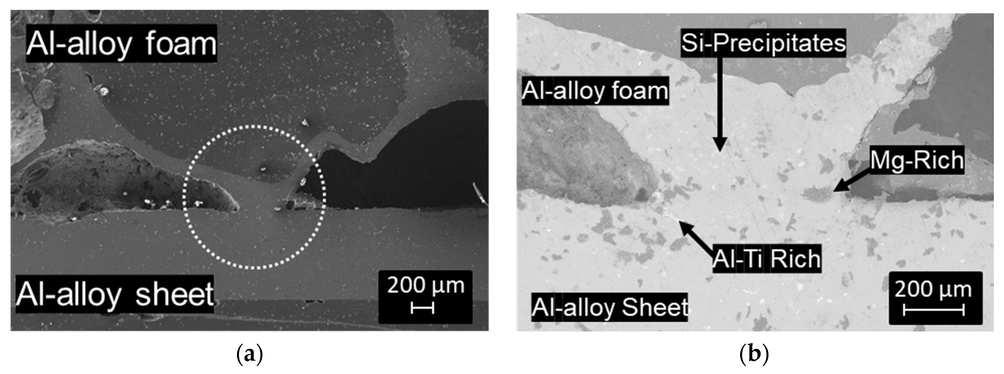
Figure 7 shows SEM micrographs of an Al-alloy foam/Al-alloy sheet joint interface produced using Al-Si-Mg-Ti amorphous alloy. Figure 7a shows a sound brazed joint produced at the interface of the joining substrates. The spot EDS analysis, conducted in the arrows positions, confirms the formation Mg-rich, Si precipitates, and Ti-rich phase, intermetallic compounds, Figure 7b. The oxygen traces were, however, observed within or in the surroundings of the intermetallic compounds, confirming the formation of oxides. The possible reasons for the oxidation during the brazing of AFS are the entrapped air inside the foam cells, the presence of oxides on the surface of amorphous joining strips and/or the oxide layer on the inner surface of the foam pores.
When the Si percentage is higher than 1.65%, the eutectic reaction takes place at 577 °C at a silicon weight percentage of 12.6%. Directly from the liquid phase Al-Si eutectic microstructures form when the Si content is 12.6% (hypoeutectic when the Si content is lower and hypereutectic when the Si content is higher). Upon slow cooling (cooling rates between 1–10 K/min), Si precipitates typically in a coarse and flaky morphology provided that no chemical modifiers are added [32]. Luo and Acoff et al., [10] reported the formation of a TiAl3 compound as the only compound after a reactive diffusion between Ti and Al in the temperature range of 516–642 °C. MgO and Al-Ti compound phases generally have higher melting points and favour the thermal stability of the joint but, on the contrary, they hinder the wettability of joining surfaces during brazing.
3.2. Microhardness Analysis
The microhardness values determined for AFS components before and after the brazing heat treatment are presented in Figure 8.
Around a 35% decrease in the average microhardness of the Al-alloy sheet was observed after the brazing process due to the grain growth (Figure 4d and Figure 6d). However, the thermal treatment studies of the Al [33] suggests that the strength and hardness properties can be recovered if brazing joining is followed by a proper solution heat treatment and ageing temper.
Instead, the microhardness values of the Al-alloy foam before and after the thermal treatment were found to be almost similar. The Al-alloy foam production process and characteristics support such behaviour. Luo and Acoff et al. [9] also subjected Al-alloy foam to heat treatments at different temperatures and reported no significant changes in the mechanical properties of Al-alloy foam.
The joints produced with Al-Cu-Mg brazing alloy showed around 15% higher microhardness values with respect to that produced with Al-Si-Mg-Ti amorphous brazing alloy. The microhardness of the secondary phase particles formed during brazing with Al-Cu-Mg amorphous alloy at 560 °C was higher by around 43% in comparison to those precipitated during brazing using Al-Si-Mg-Ti amorphous alloy at 590 °C. The higher reactivity of Al-Cu-Mg (as was observed) produced a higher amount of joining melt, resulting in precipitation of secondary phase particles with relatively higher microhardness values.
3.3. Mechanical Characterisation
AFS base components (Al-alloy sheet and Al-alloy foam) and composite panels were tested to determine the bending strength and to observe the failure modes involved. The load-crosshead displacement curves shown in Figure 9 are representative results for the AFS components. Al-6016 facing sheet curves were almost overlapped, while those of the Al-alloy foam is the average one, as the curves did not completely overlap due to the non-homogeneity of the foam in the as received and treated conditions. The curves of facing sheets and the Al-alloy foam cannot be compared directly as the Al-alloy sheet thickness (1.2 mm) was completely different from the Al-alloy foam (9 mm). After the heat treatment (thermal simulation of the brazing process), the Al-6016 sheet showed around 65% decrease in bending load compared to the as-received ones, while the Al-alloy foam showed no prominent difference in bending strength and bending behaviour before and after the heat treatment. The mechanical properties of the Al-6016 sheet are affected by brazing and can be recovered by a post-brazing heat treatment.
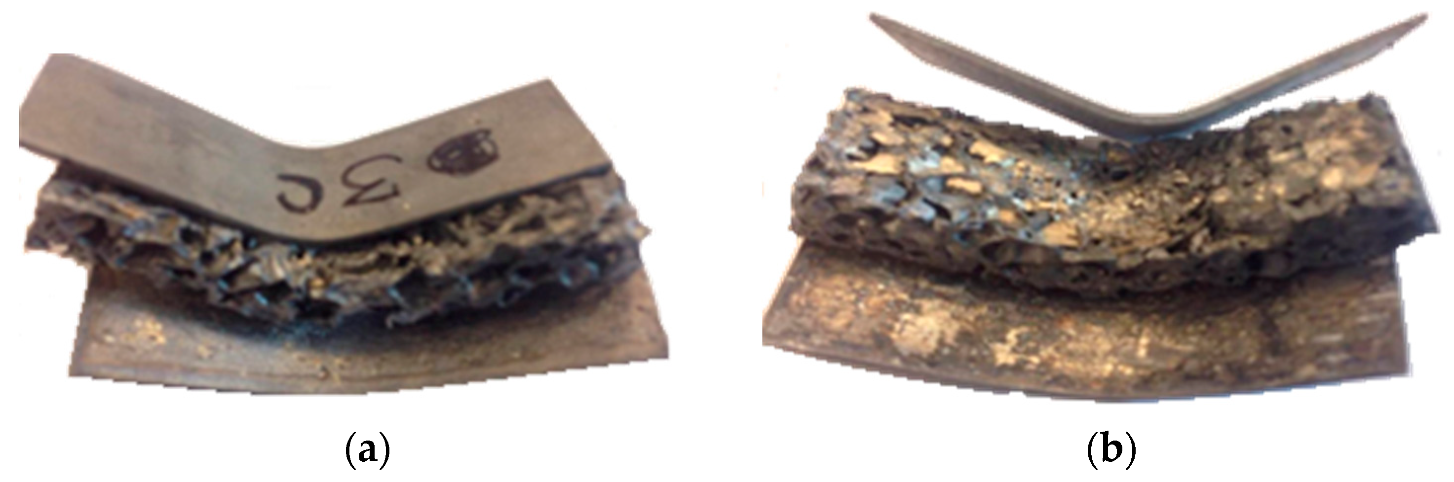
The behaviour of the Al-alloy foam sandwich composite specimens (11.4 mm thick), subjected to three-point bending tests is shown in Figure 10. The analysis of digital images and videos recorded during bending tests showed that, after the elastic behaviour, at around 100 N, the loading cylinder induced a localized deformation primarily at the loading point. With the increase in load, this deformation progressively increased and reached the underlying Al-alloy foam. This induced a sheer plastic deformation in the foam, as well as at the foam-sheet interface. When the shear stresses exceeded the apparent maximum Al-alloy sheet/Al-alloy foam joint shear strength, the failure of the AFS structure occurred with the delamination between Al-alloy sheets and foam, as can be seen in Figure 11a,b. Otherwise, in the case of higher interface strength, the failure would occur in the core material [34]. The formation of less deformable intermetallic compounds in the interface gives brittle behaviour in the joint, and this was the reason for the obtained lower joining strength and the subsequent sudden delamination.
The AFS composite specimens produced with the Al-Cu-Mg amorphous brazing alloy as joining material, displayed around 16% higher bending strength at failure compared to AFS composite specimens produced by using Al-Cu-Mg-Ti amorphous brazing alloy as joining material. The mechanical properties of AFS components can also be further improved if subjected to post-brazing heat treatment [35].
A sharp drop in load-displacement curves evidenced the delamination (Figure 11) of Al-alloy sheets when the cross-head displacement reached the 5.5 mm and 6.5 mm for AFS produced with Al-Cu-Mg alloy and Al-Si-Mg-Ti alloy, respectively, Figure 10. After these points, the cylinder load induced a bulking effect by local plastic foam deformation.
The mechanical behaviour of AFS specimens subjected to three-point bending is influenced by both the specimen specifications and test parameters. However, a general comparison has been established in Table 1 to compare approximate service temperature (assumed to be 50 °C lower than the joining temperature) and the bending load at failure results of the current work in comparison to those of produced with different bonding techniques proposed in the literature.
Failure modes, including face yielding, face wrinkling, core yielding, indentation, complete, partial, and no delamination of Al-alloy sheets were reported for AFS composite panels in the past studies [15,37,38,39,40]. Isabel et al. [41] studied the flexural behaviour of adhesively-bonded AFS panels and reported two different failure modes: (i) symmetric deformation, and (ii) asymmetric deformation, for adhesively-bonded sandwich panels where failure occurred in the core due to excessive shear stress and no delamination of facing skins was observed. However, the AFS produced in this study delaminated at relatively lower load values due to the lower joining interface strength compared to core shear strength.
AFS composites produced with the proposed joining technique failed at lower bending load in comparison to those reported by [15], where the specimen dimension and test conditions are similar, Table 1. However, the AFS composites produced with the joining technique proposed in this work can sustain higher service temperature than other joining techniques, including adhesive joining or soldering.
Unlike joining techniques based on adhesives, the soldering and brazing joining of Al-alloy sheet to Al-alloy foam gives complete metallic character to the AFS structure, which is of importance for automotive and aerospace applications, for instance. As a drawback, in the presence of particular alloying elements, intermetallic compounds can form and give a brittle behaviour to the joints. However, Swidersky et al. [42] suggested a caesium-containing flux material, as an effective solution to avoid Mg-oxides by favouring potassium magnesium fluoride formation, which has lower melting temperatures than required for oxide formation. Research in this direction is ongoing.
4. Conclusions
Joining of Al-6016 facing sheets to Al-alloy foam was carried out to produce AFS composite panels using Al-based metal glasses in an argon atmosphere.
The composition of brazing alloys was selected on the basis of precursor materials used for Al-alloy foam production. Higher diffusion of Al-Cu-Mg amorphous brazing alloy was observed into the joining substrates compared to Al-Si-Mg-Ti amorphous joining alloy.
Sound connections between the Al-alloy foam and Al-alloy sheet were achieved, however, the formation of hard and brittle intermetallic phases in the joining interface affected the maximum strength.
AFS produced in this study can be usefully applied at an operational temperature up to 520 °C. However, the idea to achieve joining of Al-alloy sheet to Al-alloy foam using Al-based amorphous alloys still needs improvement and optimization. Further improvement in joint strength of brazed AFS can replace the traditional adhesive and solder joining methods currently in practice.
Author Contributions
M.K.B. carried out the main experimental work and drafted the manuscript. D.D.S. carried out the image and microhardness analysis, G.U. and M.F. analysed the results and supervised the research activity. N.J. produced the brazing alloys for joining.
Funding
This research received no external funding from funding agencies in the public, commercial, or not-for-profit sectors.
Acknowledgments
The financial support of the Higher Education Commission (HEC) Pakistan in the form of a PhD fellowship is greatly acknowledged. The role of Mauro Raimondo and Antonio Favero for providing assistance during the mechanical characterization and SEM facility is highly appreciated.
Conflicts of Interest
The authors declare no conflict of interest in the design of the study; in the collection, analyses, or interpretation of data; in the writing of the manuscript, and in the decision to publish the results.
References
- Crupi, V.; Epasto, G.; Guglielmino, E. Impact Response of Aluminum Foam Sandwiches for Light-Weight Ship Structures. Metals 2011, 1, 98–112. [Google Scholar] [CrossRef] [Green Version]
- Banhart, J.; Seeliger, H.-W. Aluminium Foam Sandwich Panels: Manufacture, Metallurgy and Applications. Adv. Eng. Mater. 2008, 10, 793–802. [Google Scholar] [CrossRef]
- Güner, A.; Arıkan, M.; Nebioglu, M. New Approaches to Aluminum Integral Foam Production with Casting Methods. Metals 2015, 5, 1553–1565. [Google Scholar] [CrossRef] [Green Version]
- Banhart, J.; Berlin, H.; Heim, K.; Seeliger, H.; Gmbh, P.M. Light-weighting in transportation and defence using aluminium foam sandwich structures. In Proceedings of the International Symposium on Light Weighting for Defence, Aerospace and Transportation, Goa, India, 11 November 2017; pp. 1–10. [Google Scholar]
- Chen, N.; Feng, Y.; Chen, J.; Li, B.; Chen, F.; Zhao, J. Vacuum Brazing Processes of Aluminum Foam. Rare Met. Mater. Eng. 2013, 42, 1118–1122. [Google Scholar] [CrossRef]
- Matsumoto, R.; Tsuruoka, H.; Otsu, M.; Utsunomiya, H. Fabrication of skin layer on aluminum foam surface by friction stir incremental forming and its mechanical properties. J. Mater. Process. Technol. 2015, 218, 23–31. [Google Scholar] [CrossRef]
- Banhart, J.; Seeliger, H.-W. Recent Trends in Aluminium Foam Sandwich Technology Industrial Implementation of AFS Technology. Adv. Eng. Mater. 2011, 14, 1082–1087. [Google Scholar] [CrossRef]
- Polmear, I. Light Alloys-From Traditional Alloys to Nanocrystals, 4th ed.; Butterworth-Heinemann: Oxford, UK, 2006. [Google Scholar] [CrossRef]
- Luo, J.-G.; Acoff, V.L. Interfacial Reactions of Titanium and Aluminum during Diffusion Welding. Weld J. 2000, 79, 239–243. [Google Scholar]
- Banhart, J.; Seeliger, H.-W. Recent Trends in Aluminum Foam Sandwich Technology. Adv. Eng. Mater. 2012, 14, 1082–1087. [Google Scholar] [CrossRef]
- Huang, Y.; Gong, J.; Lv, S.; Leng, J.; Li, Y. Fluxless soldering with surface abrasion for joining metal foams. Mater. Sci. Eng. A 2012, 552, 283–287. [Google Scholar] [CrossRef]
- Wan, L.; Huang, Y.; Huang, T.; Lv, S.; Feng, J. Novel method of fluxless soldering with self-abrasion for fabricating aluminum foam sandwich. J. Alloys Compd. 2015, 640, 1–7. [Google Scholar] [CrossRef]
- Fleming, K.M.; Zhu, A.; Scully, J.R. Corrosion of AA6061 brazed with an Al-Si alloy: Effects of Si on metallurgical and corrosion behavior. Corrosion 2012, 68, 1126–1145. [Google Scholar] [CrossRef]
- Han, Y.; Ma, K.; Li, L.; Chen, W.; Nagaumi, H. Study on microstructure and mechanical properties of Al-Mg-Si-Cu alloy with high manganese content. Mater. Des. 2012, 39, 418–424. [Google Scholar] [CrossRef]
- Ubertalli, G.; Ferraris, M.; Bangash, M.K. Joining of AL-6016 to Al-foam using Zn-based joining materials. Compos. Part A Appl. Sci. Manuf. 2017, 96, 122–128. [Google Scholar] [CrossRef]
- Duarte, I.; Oliveira, M. Aluminium Alloy Foams: Production and Properties. In Powder Metallurgy; InTech: Rijeka, Croatia, 2012; pp. 47–72. [Google Scholar]
- Campana, G.; Ascari, A.; Fortunato, A. Laser foaming for joining aluminum foam cores inside a hollow profile. Opt. Laser Technol. 2013, 48, 331–336. [Google Scholar] [CrossRef]
- García-Moreno, F. Commercial applications of metal foams: Their properties and production. Materials 2016, 9, 85. [Google Scholar] [CrossRef] [PubMed]
- Banhart, J.; Vinod-Kumar, G.S.; Kamm, P.H.; Neu, T.R.; García-Moreno, F. Light-metal foams: Some recent developments. Ciência Tecnol. Dos Mater. 2016, 28, 1–4. [Google Scholar] [CrossRef]
- Schindelin, J.; Arganda-Carreras, I.; Frise, E.; Kaynig, V.; Longair, M.; Pietzsch, T.; Preibisch, S.; Rueden, C.; Saalfeld, S.; Schmid, B.; et al. Fiji: An open-source platform for biological-image analysis. Nat. Methods 2012, 9, 676. [Google Scholar] [CrossRef] [PubMed]
- Yu, Y.; Xu, D.; Tian, J.; Wang, D.; Wang, P.; Niu, J. Effects of Al–8.5Si–25Cu–xY filler metal foils on vacuum brazing of SiCp/Al composites. Mater. Sci. Technol. 2017, 0836, 1–11. [Google Scholar] [CrossRef]
- Qingxian, H.; Sawei, Q.; Yuebo, H. Development on Preparation Technology of Aluminum Foam Sandwich Panels. Rare Met. Mater. Eng. 2015, 44, 548–552. [Google Scholar] [CrossRef]
- Banhart, J. Manufacture, characterisation and application of cellular metals and metal foams. Prog. Mater. Sci. 2001, 46, 559–632. [Google Scholar] [CrossRef]
- Lehmhus, D.; Banhart, J. Properties of heat-treated aluminium foams. Mater. Sci. Eng. 2003, 349, 98–110. [Google Scholar] [CrossRef]
- Kailas, S.V. Chapter 6. Pase Diagram. In Material Science; Dept. of Mechanical Engineering, Indian Institute of Science: Bangalore, India, 2007; Available online: http://docplayer.net (accessed on 22 January 2018).
- Samson, S. The crsytal structure of the phase Mg2Al3. Acta Crystallogr. 1965, 19, 401–413. [Google Scholar] [CrossRef]
- Pearson Burton, W.; Villars, P.; Calvert, D.L. Pearson’s Handbook of Crystallographic Data for Intermetallic Phases; American Society for Metals: Metals Park, OH, USA, 1987; Volume 1. [Google Scholar]
- Vušanovic, I.; Voronjec, D.; Krane, M.J.M. Microsegregation Phenomena in Al-Cu-Mg Alloy with Considering of Diffusion Phenomena in Primary Phase. Facta Univ. Ser. Mech. Eng. 2001, 1, 965–980. [Google Scholar]
- Bolingbroke, R.K.; Gray, A.; Lauzon, D. Optimisation of Nocolok(TM) Brazing Conditions for Higher Strength Brazing Sheet; SAE Technical Paper: Warrendale, PA, USA, 1997. [Google Scholar] [CrossRef]
- Orman, L.; Swidersky, H.W.; Lauzon, D. Brazing of Aluminum alloys with higher magnesium content using non-corrosive fluxes. Keikinzoku Yosetsu/J. Light Met. Weld Constr. 2014, 52, 24–29. [Google Scholar]
- Moller, C.; Grann, J. Aluminum Brazing—What Matters Most: Fundamentals and Case Studies. In Proceedings of the 5th International Brazing Soldering Conference, Las Vegas, NV, USA, 22–25 April 2012; pp. 1–9. [Google Scholar]
- Makhlouf, M.M.; Guthy, H.V. The aluminum-silicon eutectic reaction: Mechanisms and crystallography. J. Light Met. 2002, 1, 199–218. [Google Scholar] [CrossRef]
- Marioara, C.D.; Andersen, S.J.; Jansen, J.; Zandbergen, H.W. The influence of temperature and storage time at RT on nucleation of the β′ phase in a 6082 Al-Mg-Si alloy. Acta Mater. 2003, 51, 789–796. [Google Scholar] [CrossRef]
- Kabir, K.; Vodenitcharova, T.; Hoffman, M. Response of aluminium foam-cored sandwich panels to bending load. Compos. Part B Eng. 2014, 64, 24–32. [Google Scholar] [CrossRef]
- Shabestari, S.G.; Wanderka, N.; Seeliger, W.; Banhart, J. Optimisation of the Strength of Aluminium Foam Sandwich (AF) Panels by Different Heat Treatments. Mater. Sci. Forum 2006, 521, 1221–1226. [Google Scholar] [CrossRef]
- Wan, L.; Huang, Y.; Lv, S.; Feng, J. Fabrication and interfacial characterization of aluminum foam sandwich via fluxless soldering with surface abrasion. Compos. Struct. 2015, 123, 366–373. [Google Scholar] [CrossRef]
- Crupi, V.; Montanini, R. Aluminium foam sandwiches collapse modes under static and dynamic three-point bending. Int. J. Impact Eng. 2007, 34, 509–521. [Google Scholar] [CrossRef]
- Duarte, I.; Vesenjak, M.; Krstulović-Opara, L.; Anžel, I.; Ferreira, J.M. Manufacturing and bending behaviour of in situ foam-filled aluminium alloy tubes. Mater. Des. 2015, 66, 532–544. [Google Scholar] [CrossRef]
- Bastawros, A. Experimental analysis of deformation mechanisms in a closed-cell aluminum alloy foam. J. Mech. Phys. Solids 2000, 48, 301–322. [Google Scholar] [CrossRef]
- Li, Z.; Zheng, Z.; Yu, J.; Qian, C.; Lu, F. Deformation and failure mechanisms of sandwich beams under three-point bending at elevated temperatures. Compos. Struct. 2014, 111, 285–290. [Google Scholar] [CrossRef]
- Duarte, I.; Teixeira-Dias, F.; Graça, A.; Ferreira, A.J.M. Failure Modes and Influence of the Quasi-static Deformation Rate on the Mechanical Behavior of Sandwich Panels with Aluminum Foam Cores. Mech. Adv. Mater. Struct. 2010, 17, 335–342. [Google Scholar] [CrossRef]
- Swidersky, H.W. Aluminium Brazing with Non-corrosive Fluxes State of the Art and Trends in NOCOLOK® Flux Technology. In Proceedings of the 6th International Conference Brazing, High Temperature Brazing and Diffusion Bonding, Aachen, Germany, 8–10 May 2001. [Google Scholar]
Figure 1.
(a) Closed-cell Al-alloy foam, (b) scanned image of resin embedded Al-alloy foam (representative) sample used for pore size/distribution analysis, (c) adjusted black and white layout (binarization) of Al-alloy foam surface by Image J software and the Identification of pores per unit area, and (d) the average equivalent pore size distribution.
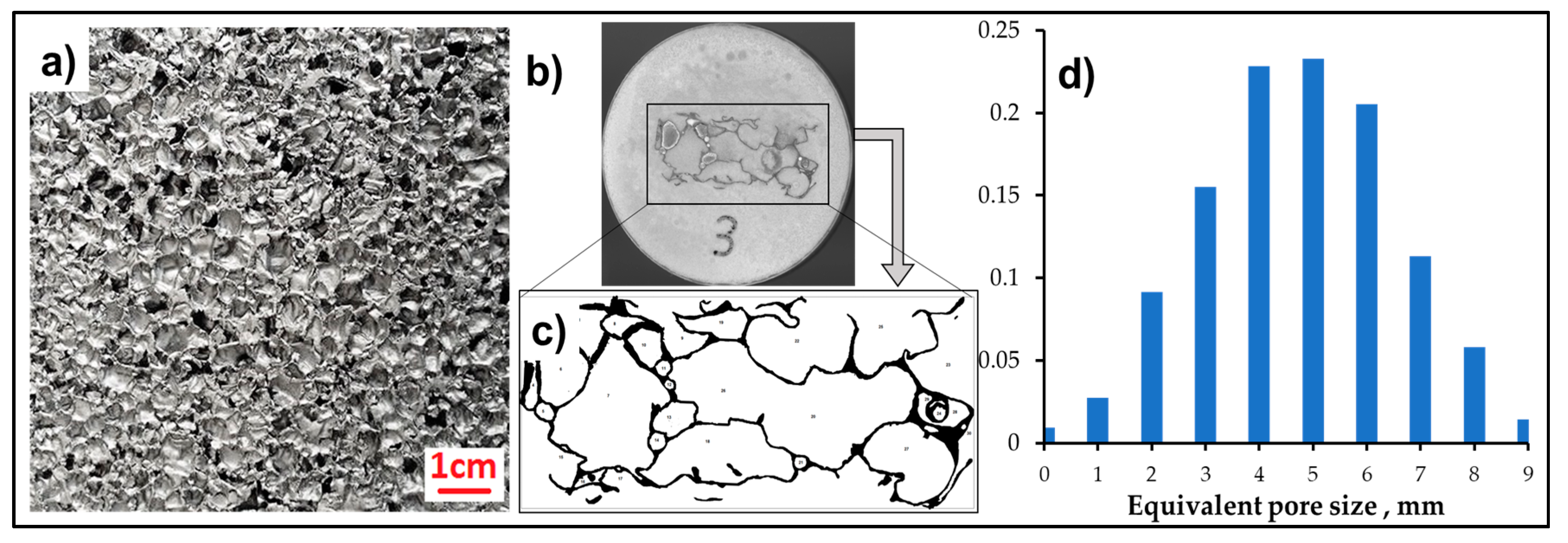
Figure 2.
(a) AFS composite stacking configuration, and (b) the three-point bending (flexural) test assembly.
Figure 2.
(a) AFS composite stacking configuration, and (b) the three-point bending (flexural) test assembly.

Figure 3.
Macrographs of polished cross-sections of AFS specimens produced using (a) Al-Cu-Mg amorphous alloy; and (b) using Al-Si-Mg-Ti amorphous alloy.
Figure 3.
Macrographs of polished cross-sections of AFS specimens produced using (a) Al-Cu-Mg amorphous alloy; and (b) using Al-Si-Mg-Ti amorphous alloy.
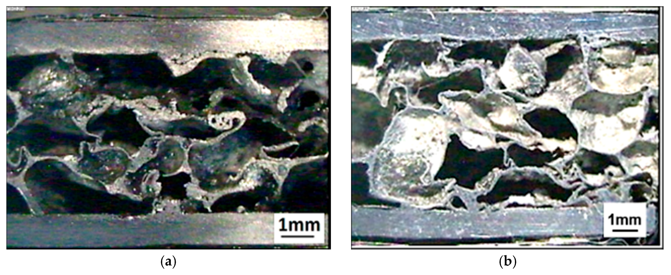
Figure 4.
Macrographs, showing the Al-alloy sheet/Al-alloy foam joint produced using Al-Cu-Mg amorphous alloy, (a) Al-alloy foam, (b,c) Al-alloy sheet/Al-alloy foam joint interface, and (d–f) Al-alloy sheet.
Figure 4.
Macrographs, showing the Al-alloy sheet/Al-alloy foam joint produced using Al-Cu-Mg amorphous alloy, (a) Al-alloy foam, (b,c) Al-alloy sheet/Al-alloy foam joint interface, and (d–f) Al-alloy sheet.

Figure 5.
SEM and back-scattered images of Al-alloy foam/Al-Cu-Mg/Al-alloy sheet interface. (a) Higher-magnification micrograph in secondary electron mode. (b) Micrograph in backscattered electron mode. Arrows indicate spot EDS analysis.
Figure 5.
SEM and back-scattered images of Al-alloy foam/Al-Cu-Mg/Al-alloy sheet interface. (a) Higher-magnification micrograph in secondary electron mode. (b) Micrograph in backscattered electron mode. Arrows indicate spot EDS analysis.

Figure 6.
Macro- and micrographs, showing the Al-alloy sheet/Al-alloy foam joint produced using Al-Si-Mg-Ti amorphous alloy, (a) Al-alloy foam, (b,c) Al-alloy sheet/Al-alloy foam joint interface, and (d–f) Al-alloy sheet.
Figure 6.
Macro- and micrographs, showing the Al-alloy sheet/Al-alloy foam joint produced using Al-Si-Mg-Ti amorphous alloy, (a) Al-alloy foam, (b,c) Al-alloy sheet/Al-alloy foam joint interface, and (d–f) Al-alloy sheet.

Figure 7.
SEM and back-scattered images of Al-alloy foam/Al-Mg-Si-Ti/Al-alloy sheet interface. (a) Micrograph in secondary electron mode. (b) Micrograph in backscattered electron mode. Arrows indicate spot EDS analysis.
Figure 7.
SEM and back-scattered images of Al-alloy foam/Al-Mg-Si-Ti/Al-alloy sheet interface. (a) Micrograph in secondary electron mode. (b) Micrograph in backscattered electron mode. Arrows indicate spot EDS analysis.

Figure 8.
Average microhardness analysis results.
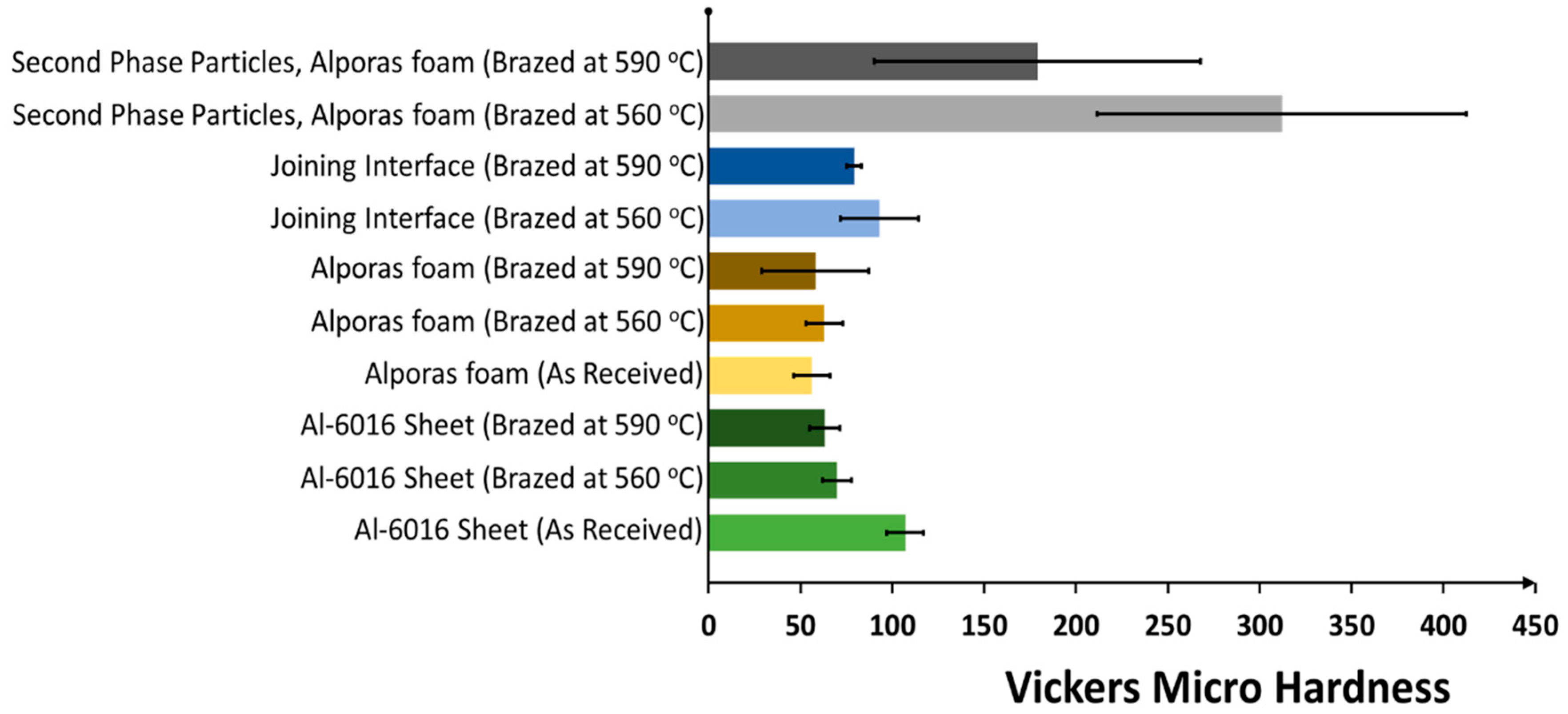
Figure 9.
Representative results for base materials of AFS specimens subjected to the three-point bending test.
Figure 9.
Representative results for base materials of AFS specimens subjected to the three-point bending test.
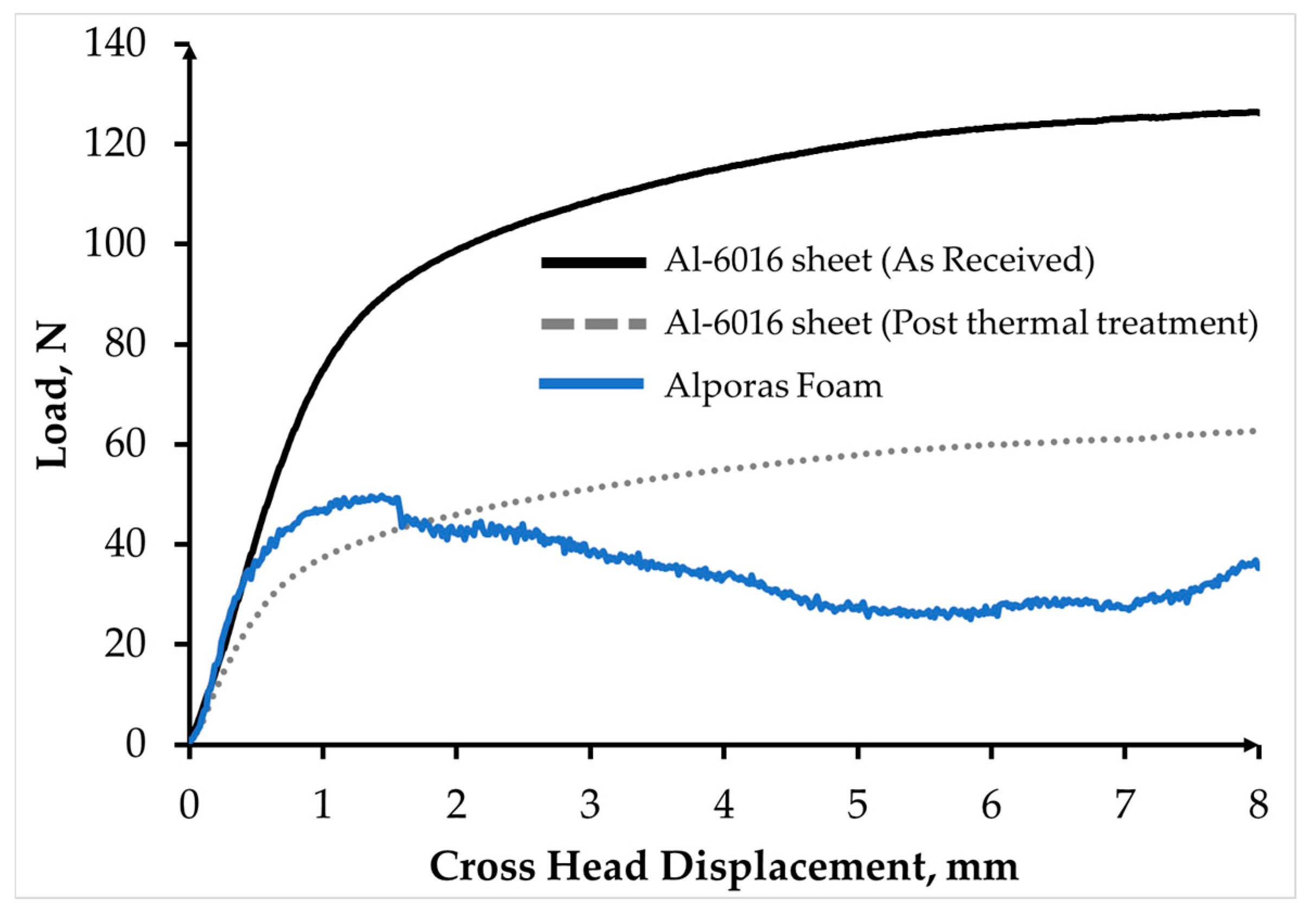
Figure 10.
Flexural behaviour of AFS components produced using Al-based amorphous brazing alloy.
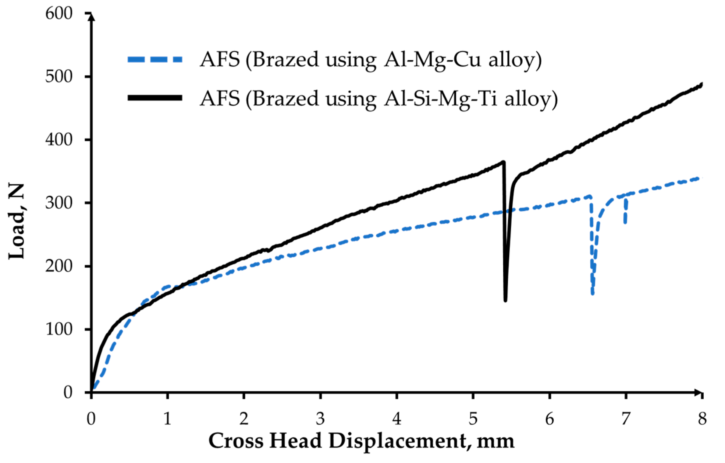
Figure 11.
Representative post-three-point bending test delaminated specimens (specimen dimensions: 60 mm × 20 mm × 11.4 mm). (a) Brazed using Al-Cu-Mg and (b) brazed using Al-Si-Mg-Ti brazing alloy.
Figure 11.
Representative post-three-point bending test delaminated specimens (specimen dimensions: 60 mm × 20 mm × 11.4 mm). (a) Brazed using Al-Cu-Mg and (b) brazed using Al-Si-Mg-Ti brazing alloy.


Table 1.
Average three-point bending test results for obtained and similar AFS components reported in the literature.
Table 1.
Average three-point bending test results for obtained and similar AFS components reported in the literature.
| Joint | Joining Parameters | Joining Material | Specimen Dimensions, (mm) | Span Length, (mm) | Approx. Service Temperature, (°C) | Bending Load at Failure, (N) | Reference |
|---|---|---|---|---|---|---|---|
| Al-6016/Al-alloy foam | 10 min at 560 °C | Al-Cu-Mg amorphous alloy | 1 l = 60 | 47 | 520 | 341 ± 30 | Current work |
| 2 b = 20 | |||||||
| 3 c = 9 | |||||||
| 4 t = 1.2 | |||||||
| Al-6016/Al-alloy foam | 10 min at 590 °C | Al-Si-Mg-Ti amorphous alloy | l = 60 | 47 | 520 | 284 ± 20 | Current work |
| b = 20 | |||||||
| c = 9 | |||||||
| t = 1.2 | |||||||
| Al-6016/Al-alloy foam | 1 min at 420 °C | Pure Zn foils | l = 60 | 47 | 380 | 785 ± 50 | [15] |
| b = 20 | |||||||
| c = 9 | |||||||
| t = 1.2 | |||||||
| Al-6016/Al-alloy foam | 5 min at 430 °C | Zn-2Al alloy strips | l = 60 | 47 | 380 | 904 ± 60 | [15] |
| b = 20 | |||||||
| c = 9 | |||||||
| t = 1.2 | |||||||
| Al 1100-0/Al-alloy foam | Room temperature | Epoxy | l = 150 | 50 | 25 | 310 | [34] |
| b = 35 | |||||||
| c = 12 | |||||||
| t = 0.34 | |||||||
| Al 3104-H19/Al-alloy foam | Room temperature | Epoxy | l = 150 | 50 | 25 | 400 | [34] |
| b = 35 | |||||||
| c = 12 | |||||||
| t = 0.34 | |||||||
| Al-5056/Al-alloy foam | 10min at 420 °C (Without vibration) | Zn6.2Al4.3Cu1.2Mg0.8Mn0.5Ag alloy | l = 60 | 40 | 380 | 1000 | [36] |
| b = 15 | |||||||
| c = 15 | |||||||
| t = 1.2 |
1 length, 2 width, 3 Core thickness, 4 Facing sheet thickness.
© 2018 by the authors. Licensee MDPI, Basel, Switzerland. This article is an open access article distributed under the terms and conditions of the Creative Commons Attribution (CC BY) license (http://creativecommons.org/licenses/by/4.0/).
Share and Cite
MDPI and ACS Style
Bangash, M.K.; Ubertalli, G.; Di Saverio, D.; Ferraris, M.; Jitai, N. Joining of Aluminium Alloy Sheets to Aluminium Alloy Foam Using Metal Glasses. Metals 2018, 8, 614. https://doi.org/10.3390/met8080614
AMA Style
Bangash MK, Ubertalli G, Di Saverio D, Ferraris M, Jitai N. Joining of Aluminium Alloy Sheets to Aluminium Alloy Foam Using Metal Glasses. Metals. 2018; 8(8):614. https://doi.org/10.3390/met8080614
Chicago/Turabian StyleBangash, Muhammad Kashif, Graziano Ubertalli, Davide Di Saverio, Monica Ferraris, and Niu Jitai. 2018. "Joining of Aluminium Alloy Sheets to Aluminium Alloy Foam Using Metal Glasses" Metals 8, no. 8: 614. https://doi.org/10.3390/met8080614
Note that from the first issue of 2016, this journal uses article numbers instead of page numbers. See further details here.