
Residual Stress Distribution and Microstructure at a Laser Spot of AISI 304 Stainless Steel Subjected to Different Laser Shock Peening Impacts

Abstract
:
1. Introduction
2. Experimental Procedures
2.1. Specimen Preparation

| Type | Value |
|---|---|
| Tensile strength, (σb) (kgf/mm2) | 520 |
| Specific gravity, (d) (g/cm3) | 7.93 |
| Yield strength, (σ) (kgf/mm2) | 205 |
| Vickers-hardness (HV) | 200 |
| Elongation, (δ) (%) | 40 |
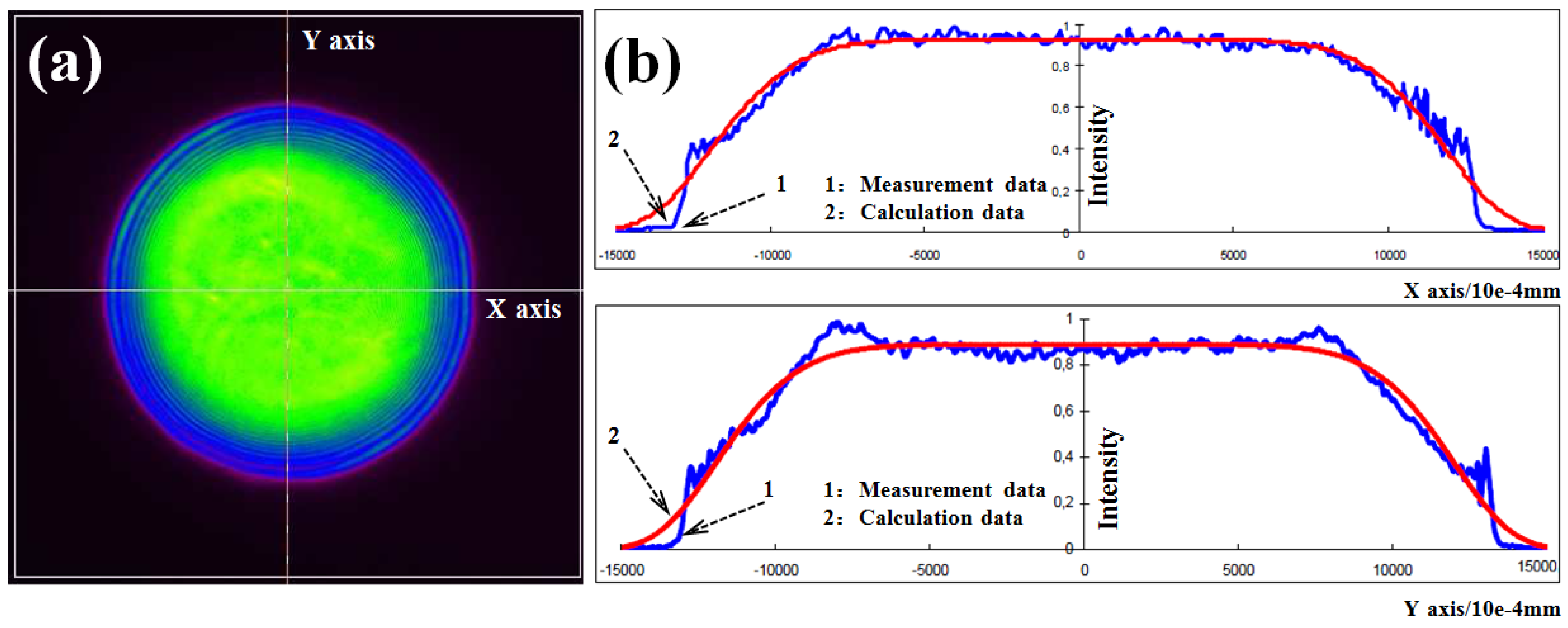
2.2. LSP Experiment

2.3. Residual Stress Measurement and Microstructural Observations
3. Result and Discussions
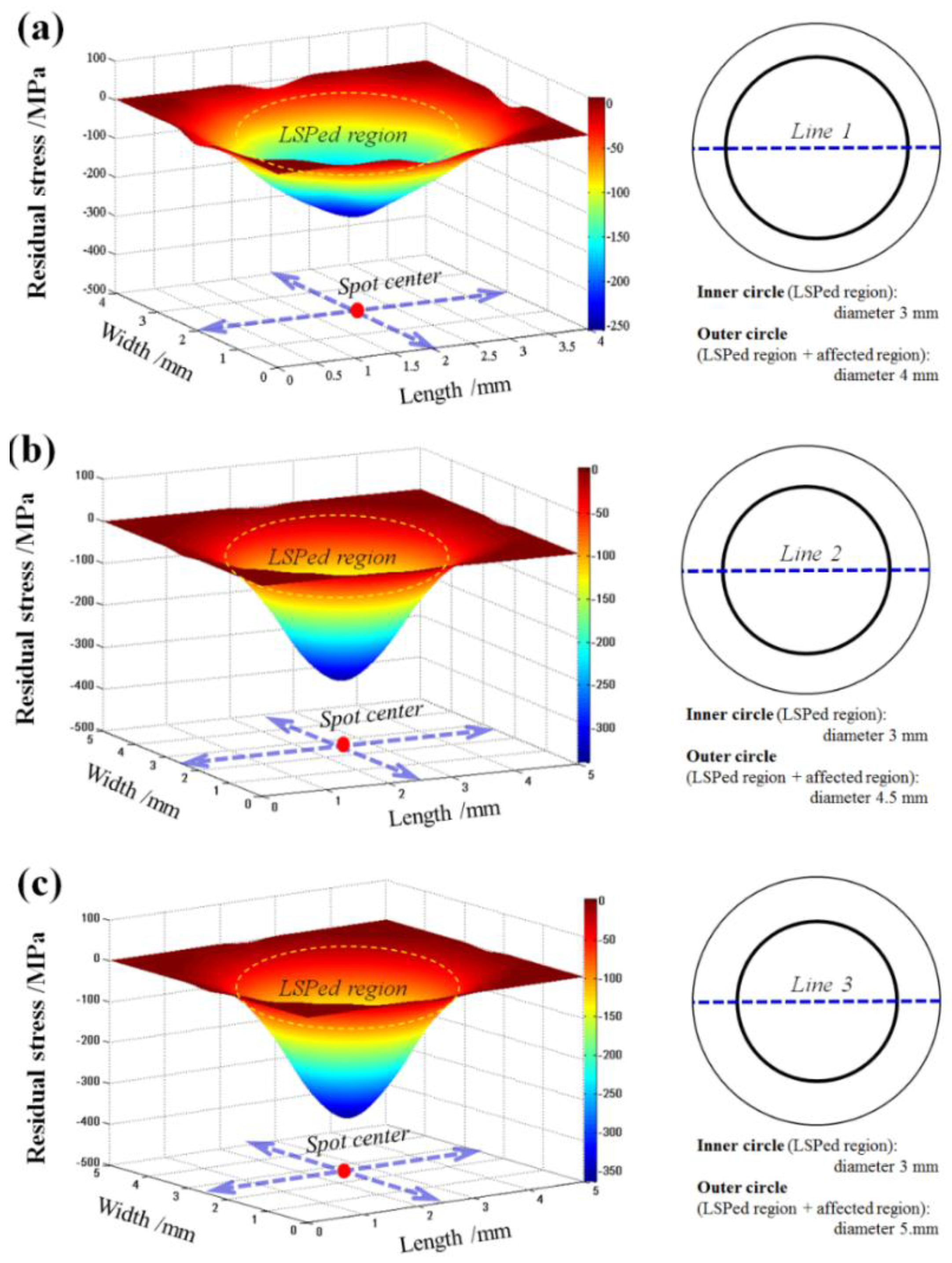
3.1. Surface Residual Stress Distribution at a Single Laser Spot

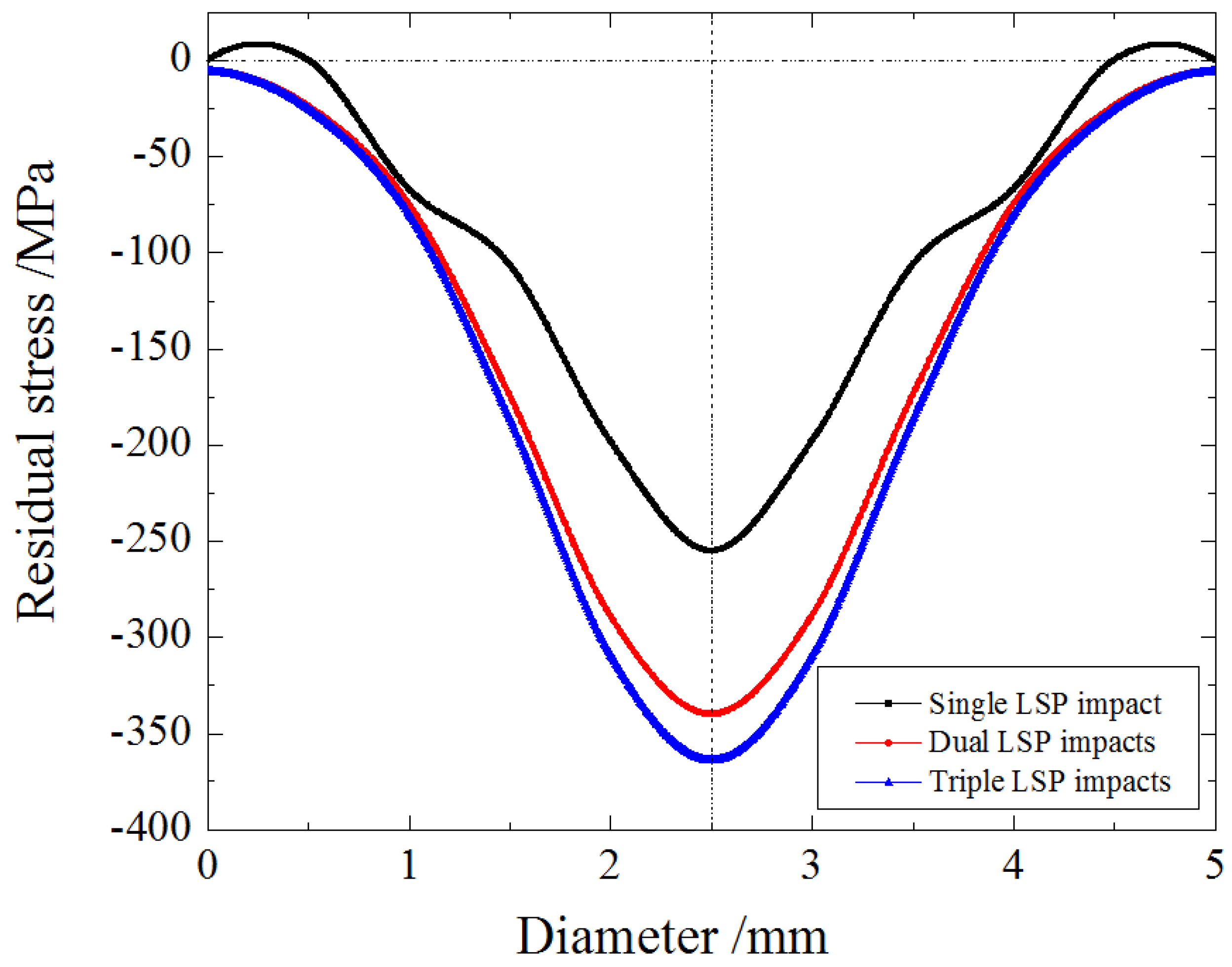
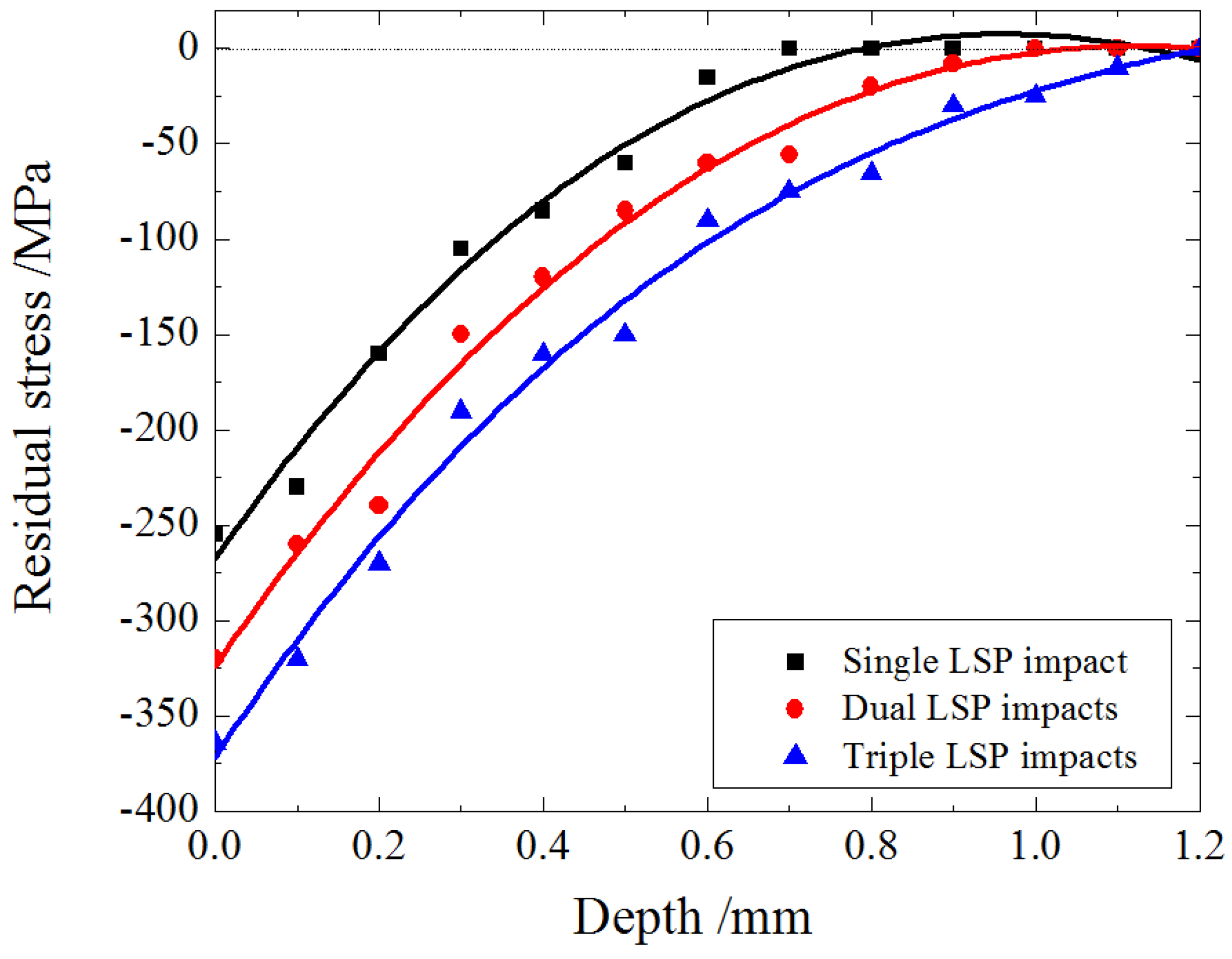
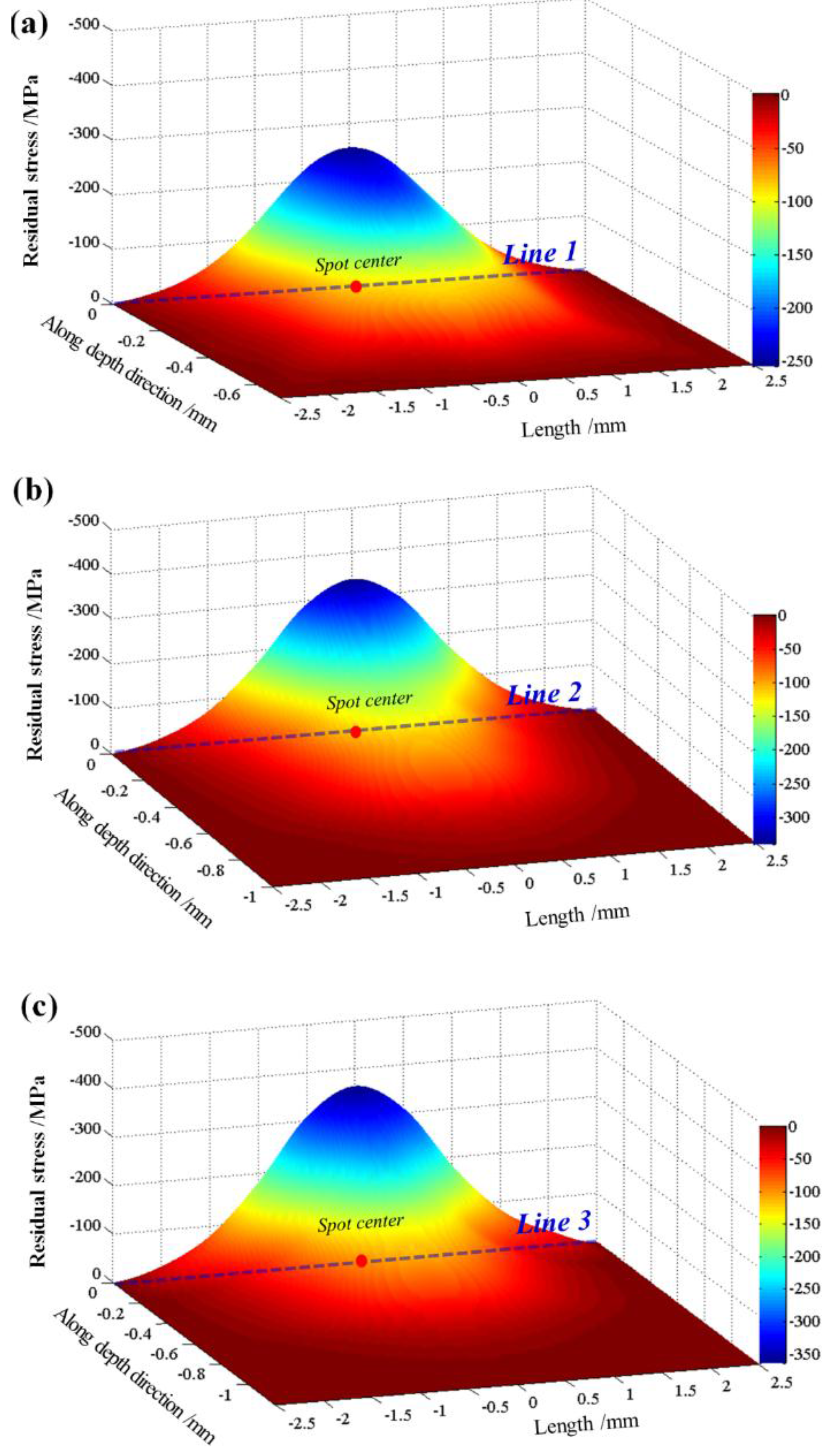
3.2. Residual Stress Distribution in Depth Direction along the Diameter of Laser Spot

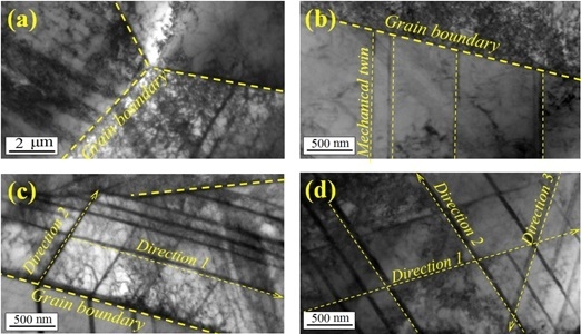
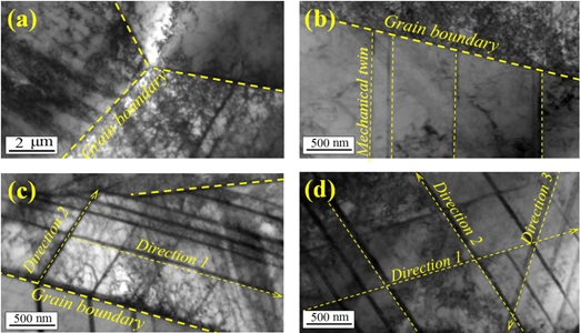
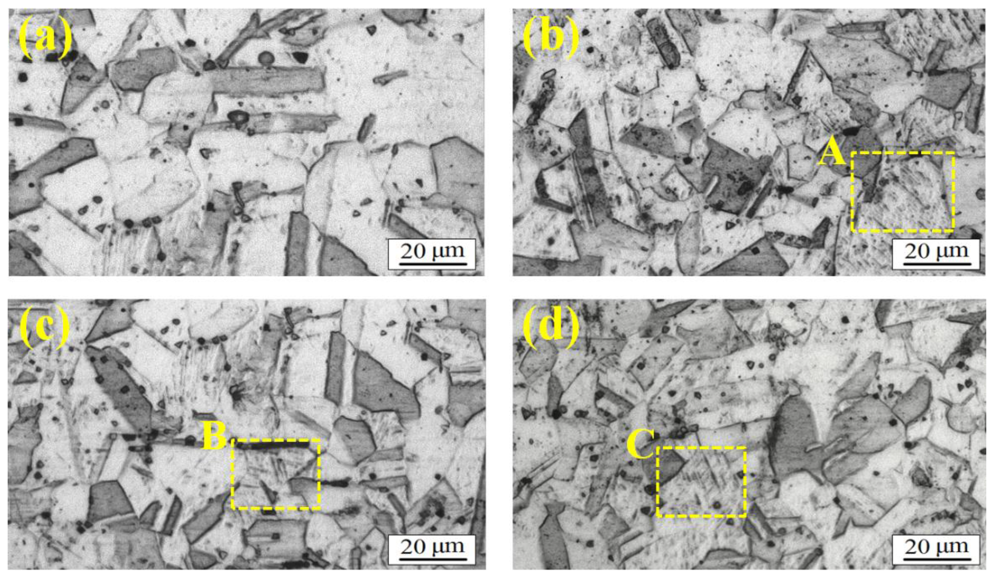
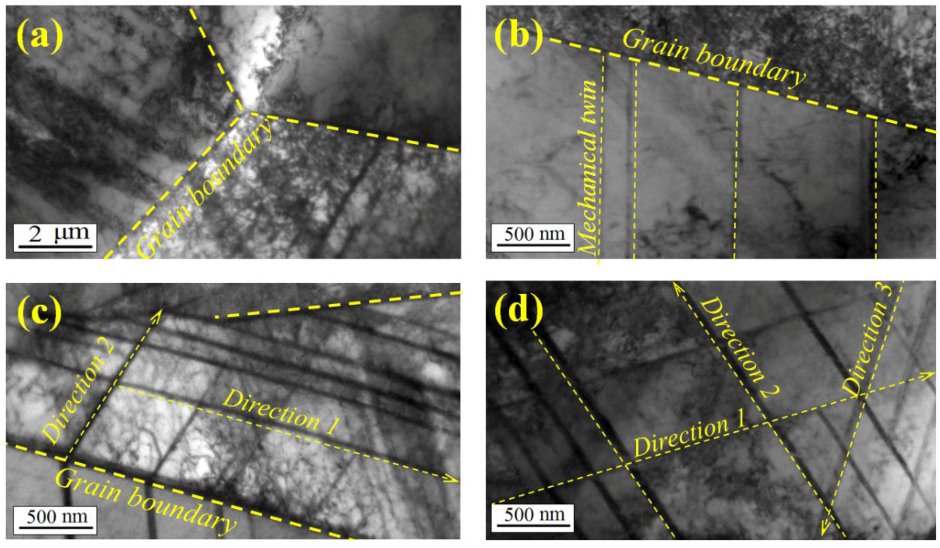
3.3. Metallographic Observation and Microstructural TEM Characterization
4. Conclusions
Acknowledgments
Author Contributions
Conflicts of Interest
References
- Ye, C.; Suslov, S.; Fei, X.L.; Cheng, G.J. Bimodal nanocrystallization of NiTi shape memory alloy by laser shock peening and post-deformation annealing. Acta Mater. 2011, 59, 7219–7227. [Google Scholar] [CrossRef]
- Trdan, U.; Grum, J. SEM/EDS characterization of laser shock peening effect on localized corrosion of Al alloy in a near natural chloride environment. Corros. Sci. 2014, 82, 328–338. [Google Scholar] [CrossRef]
- Trdan, U.; Grum, J. Evaluation of corrosion resistance of AA6082-T651 aluminium alloy after laser shock peening by means of cyclic polarisation and ElS methods. Corros. Sci. 2012, 59, 324–333. [Google Scholar] [CrossRef]
- Wang, J.T.; Zhang, Y.K.; Chen, J.F.; Zhou, J.Y.; Ge, M.Z.; Lu, Y.L.; Li, X.L. Effects of laser shock peening on stress corrosion behavior of 7075 aluminum alloy laser welded joints. Mater. Sci. Eng. A 2015, 647, 7–14. [Google Scholar] [CrossRef]
- Trdan, U.; Porro, J.A.; José, L.; Ocaña, J.G. Laser shock peening without absorbent coating (LSPwC) effect on 3D surface topography and mechanical properties of 6082-T651 Al alloy. Surf. Coat. Technol. 2012, 208, 109–116. [Google Scholar] [CrossRef]
- Jia, W.J.; Hong, Q.; Zhao, H.Z.; Li, L.; Han, D. Effect of laser shock peening on the mechanical properties of a near-α titanium alloy. Mater. Sci. Eng. A 2014, 606, 354–359. [Google Scholar] [CrossRef]
- Correa, C.; de Lara, L.R.; Díaz, M.; Porro, J.A.; García-Beltrán, A.; Ocaña, J.L. Influence of pulse sequence and edge material effect on fatigue life of Al2024-T351 specimens treated by laser shock processing. Int. J. Fatigue 2015, 70, 196–204. [Google Scholar] [CrossRef]
- Lu, J.Z.; Luo, K.Y.; Yang, D.K.; Cheng, X.N.; Hu, J.L.; Dai, F.Z.; Qi, H.; Zhang, L.; Zhong, J.S.; Wang, Q.W.; Zhang, Y.K. Effects of laser peening on stress corrosion cracking (SCC) of ANSI 304 austenitic stainless steel. Corros. Sci. 2012, 60, 145–152. [Google Scholar] [CrossRef]
- Lu, J.Z.; Luo, K.Y.; Zhang, Y.K.; Cui, C.Y.; Sun, G.F.; Zhou, J.Z.; Zhang, L.; You, J.; Chen, K.M.; Zhong, J.W. Grain refinement of LY2 aluminum alloy induced by ultra-high plastic strain during multiple laser shock processing impacts. Acta Mater. 2010, 58, 3984–3994. [Google Scholar] [CrossRef]
- Lu, J.Z.; Luo, K.Y.; Zhang, Y.K.; Sun, G.F.; Gu, Y.Y.; Zhou, J.Z.; Ren, X.D.; Zhang, X.C.; Zhang, L.F.; Chen, K.M.; et al. Grain refinement mechanism of multiple laser shock processing impacts on ANSI 304 stainless steel. Acta Mater. 2010, 58, 5354–5362. [Google Scholar] [CrossRef]
- Zhan, K.; Jiang, C.H.; Ji, V. Uniformity of residual stress distribution on the surface of S30432 austenitic stainless steel by different shot peening processes. Mater. Lett. 2013, 99, 61–64. [Google Scholar] [CrossRef]
- Nikitin, I.; Altenberger, I. Comparison of the fatigue behavior and residual stress stability of laser-shock peened and deep rolled austenitic stainless steel AISI 304 in the temperature range 25–600 °C. Mater. Sci. Eng. A 2007, 465, 176–178. [Google Scholar] [CrossRef]
- Withers, P.; Bhadeshia, H. Residual stress Part 2—Nature and origins. Mater. Sci. Technol. 2001, 17, 65–355. [Google Scholar] [CrossRef]
- Li, J.; Liao, Y.L.; Suslov, S.; Cheng, G.J. Laser shock-based platform for controllable forming of nanowires. Nano Lett. 2012, 12, 3224–3230. [Google Scholar] [CrossRef] [PubMed]
- Chu, J.P.; Rigsbee, J.M.; Banas, G.; Elsayed-Ali, H.E. Laser shock processing effects on surface microstructure and mechanical properties of low carbon steel. Mater. Sci. Eng. A 1999, 260, 260–268. [Google Scholar] [CrossRef]
- Tao, N.R.; Wang, Z.B.; Tong, W.P.; Sui, M.L.; Lu, J.; Lu, K. An investigation of surface Nano crystallization mechanism in Fe induced by surface mechanical attrition treatment. Acta Mater. 2002, 50, 4603–4616. [Google Scholar] [CrossRef]
- Bohn, R.; Haubopld, T.; Birringer, R.; Gleiter, H. Nanocrystalline intermetallic compounds—An approach to ductility? Scr. Metall. Mater. 1991, 25, 811–816. [Google Scholar] [CrossRef]
- Lu, K.; Wang, J.T.; Wei, W.D. A new method for synthesizing nanocrystalline alloys. J. Appl. Phys. 1991, 69, 522–531. [Google Scholar] [CrossRef]
- Chen, M.W.; Ma, E.; Hemke, K.J.; Sheng, H.W.; Wang, Y.M.; Cheng, X.M. Deformation twinning in nanocrystalline aluminum. Science 2003, 300, 1275–1277. [Google Scholar] [CrossRef] [PubMed]
© 2015 by the authors; licensee MDPI, Basel, Switzerland. This article is an open access article distributed under the terms and conditions of the Creative Commons by Attribution (CC-BY) license (http://creativecommons.org/licenses/by/4.0/).
Share and Cite
Zhang, W.; Lu, J.; Luo, K. Residual Stress Distribution and Microstructure at a Laser Spot of AISI 304 Stainless Steel Subjected to Different Laser Shock Peening Impacts. Metals 2016, 6, 6. https://doi.org/10.3390/met6010006
Zhang W, Lu J, Luo K. Residual Stress Distribution and Microstructure at a Laser Spot of AISI 304 Stainless Steel Subjected to Different Laser Shock Peening Impacts. Metals. 2016; 6(1):6. https://doi.org/10.3390/met6010006
Chicago/Turabian StyleZhang, Wenquan, Jinzhong Lu, and Kaiyu Luo. 2016. "Residual Stress Distribution and Microstructure at a Laser Spot of AISI 304 Stainless Steel Subjected to Different Laser Shock Peening Impacts" Metals 6, no. 1: 6. https://doi.org/10.3390/met6010006