Article

Mechanism of Friction and Wear in MoS2 and ZDDP/F-PTFE Greases under Spectrum Loading Conditions

Materials Science and Engineering Department, University of Texas at Arlington, 501 West First Street, Rm. 231, Arlington, TX 76019, USA
*
Author to whom correspondence should be addressed.
Lubricants 2015, 3(4), 687-711; https://doi.org/10.3390/lubricants3040687
Submission received: 26 July 2015 / Revised: 8 December 2015 / Accepted: 9 December 2015 / Published: 18 December 2015
(This article belongs to the Special Issue Tribofilms and Solid Lubrication)

Abstract

:
Two different greases formulated using MoS2 and a combination of ZDDP and functionalized PTFE (F-PTFE) were examined under spectrum loading conditions where loads, frequency, and duration of the steps were treated as variables. Combination of ZDDP and F-PTFE were synergistic resulting in a significant reduction in the wear and friction under spectrum loading condition. Decreasing the time step during the ramp up and ramp down cycles resulted in larger wear for the grease containing MoS2 particles in comparison to ZDDP/F-PTFE in grease. The tribofilm formed on the surface was analyzed using various characterization techniques like SEM, EDS, and Stereo Optical Microscopy. Tribofilms from MoS2 additives had extensive amounts of abrasive and adhesive wear and showed the formation of MoS2 on the surface on the other hand the tribofilms from ZDDP/F-PTFE had smaller amounts of severe wear and exhibited patchy tribofilms of Zn-phosphates as well as sulfides of Zn and Fe.

1. Introduction

Greases can be considered as semi-solid lubricants consisting of a thickener material, which is generally a soap that is dispersed in mineral or synthetic oils. Greases have gained prominence in the lubricant industry since the onset of the industrial revolution wherein machine parts had to be lubricated and lube oils had limited effectiveness. They are used in applications wherein lube oils cannot stay in place and frequent lubrication is unnecessary. Soaps of lithium, calcium, and sodium are commonly used as thickeners that form a large entanglement network that is responsible for trapping the oil [1,2,3,4]. The rheological as well as lubricating properties of the grease depend on its constituents and the microstructure achieved during its production.
MoS2 has been used as a solid lubricant as well as an EP additive for greases in addition to other solid lubricants such as graphite, PTFE, and talc. The lamellar structures of the MoS2 and graphite particles are mainly responsible for their load bearing capabilities wherein the layers that are interconnected by weak Van der Waals forces are sheared and deposited onto the interacting surfaces thereby preventing the contact in between asperities and protecting the surface from further seizure, wear, and abrasion [5,6,7,8,9]. ZDDP has been widely used as an anti-wear (AW) additive and as a mild anti-oxidant as well [10,11,12,13,14,15,16]. ZDDP forms protective tribofilms that are hard and glassy in nature; the other advantages that ZDDP has is the ease of manufacturing and low costs. ZDDP has been extensively used in engine oils owing to these properties. ZDDP is also used for greases as an effective AW additive that is generally used at lower operating temperatures [17,18].
PTFE on the other hand has been used as a friction modifier either by itself or in a lubricant. PTFE has known to increase the load bearing capability when used with grease [17,19,20]. In a study by Stolarski et al. [21,22], it was seen that a thin layer of PTFE adheres to the interacting surface due to a physical reaction in between PTFE and the metal substrate. It was also shown that due to the mechanical fracture of the PTFE chain, chemical reactions are induced on the interacting surfaces where asperity contact is the highest. However under prolonged loads, PTFE suffers from cold-flow and leads to an increase in the wear rate. Some of the recent studies have shown that a combination of ZDDP and PTFE is known to be synergistic that yields superior wear and weld performance [17,18,23]. Suresh et al. [18,23], used irradiated PTFE (functionalized PTFE or F-PTFE) that had carboxylic functionality with a combination of ZDDP; they reported strong synergism between the ZDDP and F-PTFE used in greases. In a study by Aswath et al. [20], strong interaction between fluorinated-ZDDP and PTFE was shown to be the reason for the superior wear and weld performance for oils and greases [20].
In the current study, two different formulations are prepared in lithium-base greases and tested in a Four-ball tribometer in accordance to ASTM D2266 standard. However, actual components including roller bearings are subjected to varied loads and frequency and hence there is a need to conduct wear tests under spectrum loading conditions. A recent study on the role of morphology of MoS2 on wear and friction behavior under spectrum loading showed that presence of sharp edges on the MoS2 particles lead to increased wear [24]. The role of anti-wear chemistry on wear and friction characteristics of greases under spectrum loading conditions forms the basis of this work.

2. Experimental Procedure

2.1. Additive Chemistries and Formulation of Greases

Two grease blends were prepared in batches of approximately 200 g. The Lithium-base grease used in the study was Texaco Marfak Multipurpose grease. It had a NLGI grade of 2 and had a dropping point of 188 °C. The thickener type used was lithium 12-hydroxystearate. The grease had a kinematic viscosity of 220 cSt at 40 °C. A Kitchen Aid stand mixer with a flat beater was used for blending and had a power rating of 250 W and a capacity of 1 gallon.
  • The first grease blend was prepared using Techfine MoS2 that was supplied by Climax Molybdenum (Phoenix, AZ). A total of 3 wt.% was used in the base grease. The average particle size of MoS2 was in a range of 5–20 µm. The mixture was blended using a kitchen aid mixer for 2 h at a speed setting of 2 on a 10-point scale. After an interval of 15 to 20 min, the blender was stopped and a spatula was used to manually mix the content in the steel bowl of the blender that ensured homogeneity and adequate blending of the grease.
  • The second grease blend was prepared using a mixture of functionalized PTFE-MP1150 (Poly tetrafluorethylene) supplied by Dupont and a secondary ZDDP (Zinc dialkyl dithiophosphate). PTFE is a well-known anti-friction additive and ZDDP has been used extensively as an anti-wear additive for engine oils and other lubricants. It was particularly interesting to formulate grease with these additives as they are known to be synergistic [17,18] and to evaluate their performance under spectrum loading conditions. About 3 wt.% of ZDDP in oil (68 wt.% ZDDP and 32 wt.% mineral base oil) and 2 wt.% of F-PTFE was used in lithium base grease and the mixture was blended in a kitchen aid mixer for 2 h at a speed setting of 2 on a 10-point scale. This particular combination of chemistries was chosen as it was shown to have a good balance of wear protection and extreme pressure properties at this treat rate [17,18]. In addition, the cost of the additive package with 3 wt. % ZDDP and 2 wt.% PTFE is less than that of 3 wt.% MoS2 at current market prices.
The blended greases were tested in a four-ball tribometer to evaluate the wear and friction performance. Before testing the greases, they were stirred using a spatula so as to ensure the consistency of the grease. Table 1 provides a brief overview of the grease formulations and the additives used.
Table 1. Overview of grease formulation and additives used.
Sl. NoBase GreaseAdditiveWeight % of Additive
Blend 1Lithium 12 hydroxystearate (NLGI grade 2)MoS23 wt.%
Blend 2Lithium 12 hydroxystearate (NLGI grade 2)ZDDP + F-PTFEZDDP: 3 wt.%;
F-PTFE: 2 wt.%

2.2. Four-Ball Tribometer Tests

The four-ball wear tests were conducted in a continuous sliding mode under boundary lubrication regime using a Plint TE92 Four-ball Tribometer. There were six different tests that were conducted which could be classified on the basis of the variables such as load and speed that were altered during the test. The tests wherein the load was varied keeping other variables fixed were termed as “Cyclic Loading” tests and when the speed was varied while maintaining all other variables constant were termed as “Cyclic Frequency” tests. The test was conducted using three steel balls placed in a chuck that is locked using a cage and a fourth ball is rotated against the three stationary balls with the lubricating medium in between. The four-balls are made up of E52100 steel (Bearing quality aircraft grade steel) and are ½” in (12.5 mm) diameter. Table 2 gives the details of various test conditions that were used in the study.
Table 2. Overview of different test conditions used in the study.
Test No.Test ConditionsType of TestConstant ValuesGraphical Representation
Test 180-40-80-40 (Kg)-15 min stepRamp-down1200 RPM, 75 °C, 72,000 cycles Lubricants 03 00687 i001
Test 280-40-80-40 (Kg)-7.5 min stepRamp-down1200 RPM, 75 °C, 72,000 cycles Lubricants 03 00687 i002
Test 340-80-40-80 (Kg)-15 min stepRamp-up1200 RPM, 75 °C, 72,000 cycles Lubricants 03 00687 i003
Test 440-80-40-80 (Kg)-7.5 min stepRamp-up1200 RPM, 75 °C, 72,000 cycles Lubricants 03 00687 i004
Test 51800-1200-600 (RPM), (13.3-20-40 (min))Ramp-down40 kg, 75 °C, 72,000 cycles Lubricants 03 00687 i005
Test 6600-1200-1800 (RPM), (40-20-13.3 (min))Ramp-up40 kg, 75 °C, 72,000 cycles Lubricants 03 00687 i006
The cyclic loading tests were categorized as Ramp-up and Ramp-down conditions wherein the tests were started with initial load of 40 kg and were terminated at a final load of 80 kg and vice versa. These tests were further classified on the basis of load step sizes of 7.5 min and 15 min each. The rpm and test temperature were maintained at 1200 rpm and 75 °C. The cyclic frequency tests were classified as Ramp-up and Ramp-down conditions wherein the frequency was varied from 600 rpm to 1800 rpm in steps of 600 rpm and vice versa. The load and test temperature were maintained at 40 kg and 75 °C and the total number of cycles were limited to a total of 72,000 in every case.
Tests 1 to 4 are known as “Cyclic Loading” tests and the tests 5 and 6 are known as “Cyclic Frequency” tests. Tests 1, 2, and 5 can be categorized under “Ramp-down” tests wherein the test begins at a higher load or frequency and terminates at a corresponding lower value. On a similar basis, Tests 3, 4, and 6 can be categorized under “Ramp-up” tests wherein the tests begin at a lower load or frequency and terminate at a higher load or frequency. All the tests were run in duplicate to avoid any discrepancy in the data and had 72,000 cycles maintained constant for each test. After the termination of every test, the three stationary steel balls were retrieved and analyzed to determine the WSD (Wear Scar Diameter).

2.3. Scanning Electron Microscopy (SEM) and Stereo-Optical Microscopy Studies

Stereo-Optical microscope (model type: Nikon SMZ 1500) was used to image the wear scars formed on the three stationary steel balls after the four-ball tests. The steel balls were cleaned using hexane and were mounted on a specially designed sample holder; which were then imaged at a magnification of 100× on the microscope. The images were analyzed using the software provided by Quartz Imaging Corporation to determine the wear scar diameter (WSD) for all the three steel balls and an average value was reported.
A scanning electron microscope (model type: Hitachi S-3000N) was used in the Secondary electron (SE) mode to image the wear surfaces at an accelerating voltage between 15 and 20 kV. Carbon tape was used to maintain good electrical contact in between the steel balls and sample holder. Specific areas on the surface that were of interest were imaged at a higher magnification to understand the wear mechanism. The energy dispersive spectroscopy (EDS) microanalyzer unit (model type: EDAX genesis) attached to the SEM was used to study the elemental composition of wear surface imaged in the secondary electron mode.

3. Results

The following section discusses the results obtained from the four-ball tribometer, the wear scar dimension, EDS elemental maps, and an in-depth analysis of the wear surface using the SEM. The effect of anti-wear additive chemistry on spectrum loading conditions and synergism between the additives is examined.

3.1. Scanning Electron Microscopy of F-PTFE and MoS2 Particles

The secondary electron images were obtained for both MoS2 and F-PTFE particles at an acceleration voltage of 10 kV to 15 kV. Figure 1 compares the particle morphology of MoS2 and F-PTFE. It can be clearly seen that the MoS2 particles have sharp edges and corners whereas the F-PTFE particles are much smoother and have rounded edges. The problem of surface charging was minimized by sputtering the F-PTFE particles with silver. The F-PTFE particles are agglomerated and much larger than the 200 nm primary particle size of the individual particles.
Figure 1. (a) SEM images of MoS2 particles at 500×; (b) SEM images of F-PTFE particles at 100×.
Lubricants 03 00687 g001

3.2. ASTM D2266 Standard

Baseline tests were conducted using ASTM D2266 for the greases with MoS2 and ZDDP + F-PTFE. Figure 2a,b compares the coefficient of friction (COF) and dimensions of the wear scar. The coefficient of friction (COF) in the case of MoS2 increases to 0.07 and stays high for the duration of the test with minimal drops where as in the case of ZDDP + F-PTFE grease it can be seen that the COF remains low (≈0.03) for the first half of the test and the rises to about 0.05 and stabilizes. The wear scar diameters (WSD) are reported in µm and it can be clearly seen that the grease with MoS2 particles exhibits a wear scar diameter that is approximately twice that of the grease with ZDDP and F-PTFE.
Figure 2. (a) COF values; and (b) Wear Scar Diameters for grease with MoS2 and grease with ZDDP + F-PTFE under ASTM D2266 standard; (c) Wear Scar Diameters for grease with MoS2 and grease with ZDDP + F-PTFE under Spectrum Loading Conditions.
Lubricants 03 00687 g002

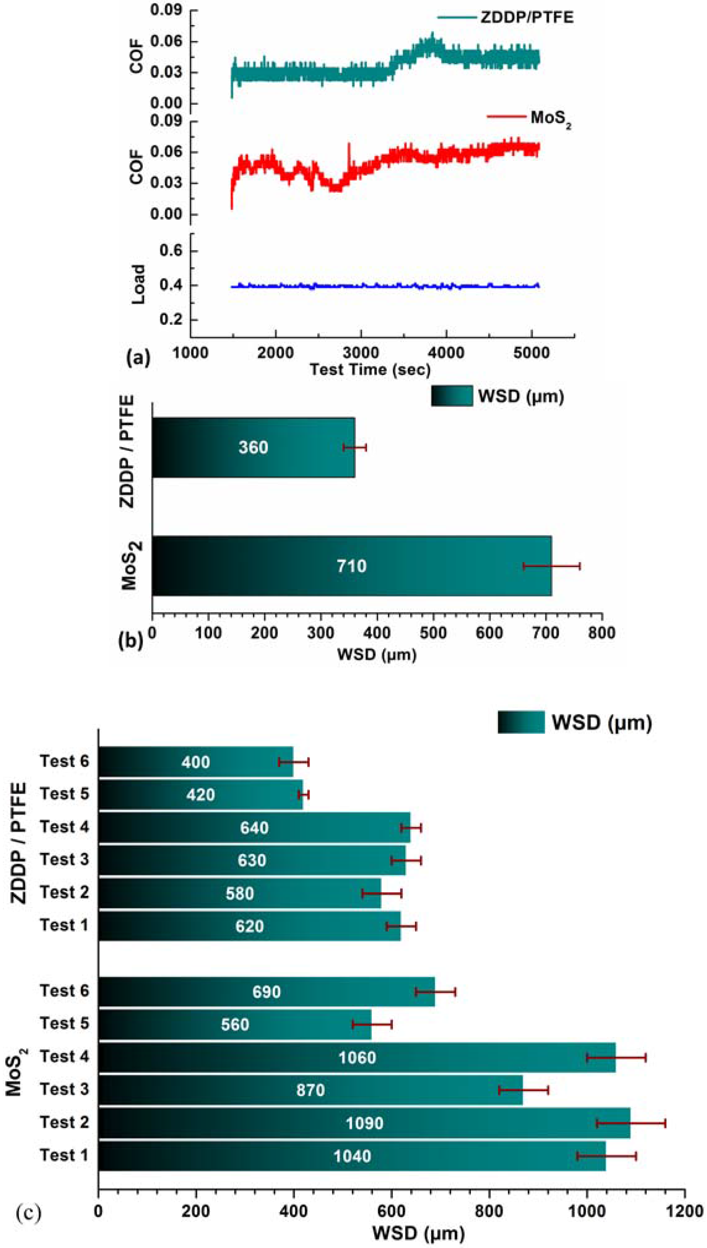
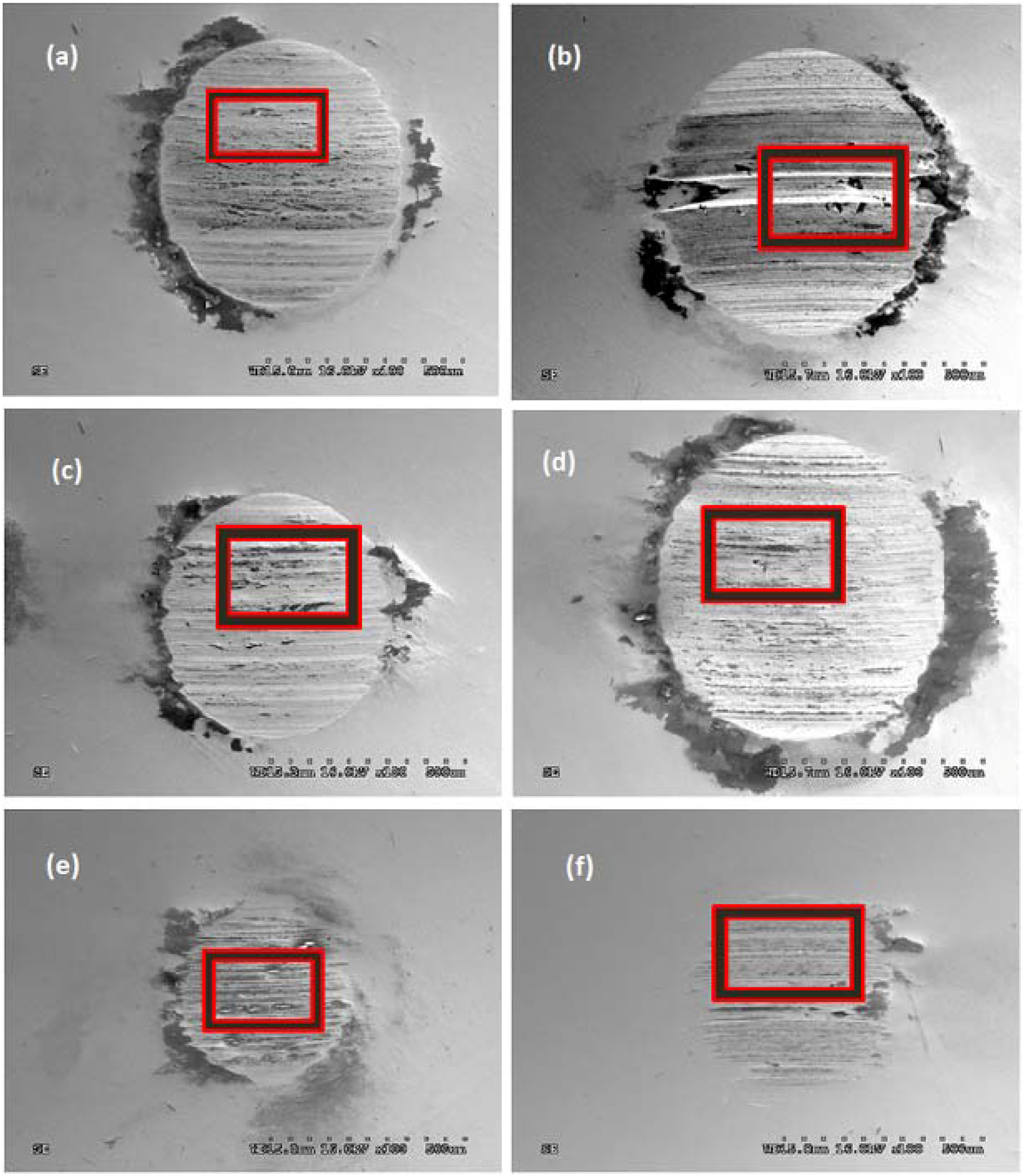
3.3. Analysis of Wear Scar Diameter (WSD) for Spectrum Loading Tests

The WSD was obtained for all the test balls using the method described in the Section 2.3 and an average value was reported. Figure 2c gives a representation of the wear numbers plotted in the form of a bar chart. The Test 1 to Test 6 represent a different set of spectrum loading conditions as summarized in Table 2. It can be seen that in every case the WSD in the MoS2 grease is much larger when compared to the grease with ZDDP + F-PTFE. When cyclic frequency tests are compared to cyclic load tests it can be seen that WSD are always smaller for the cyclic frequency tests irrespective of the choice of anti-wear additive.

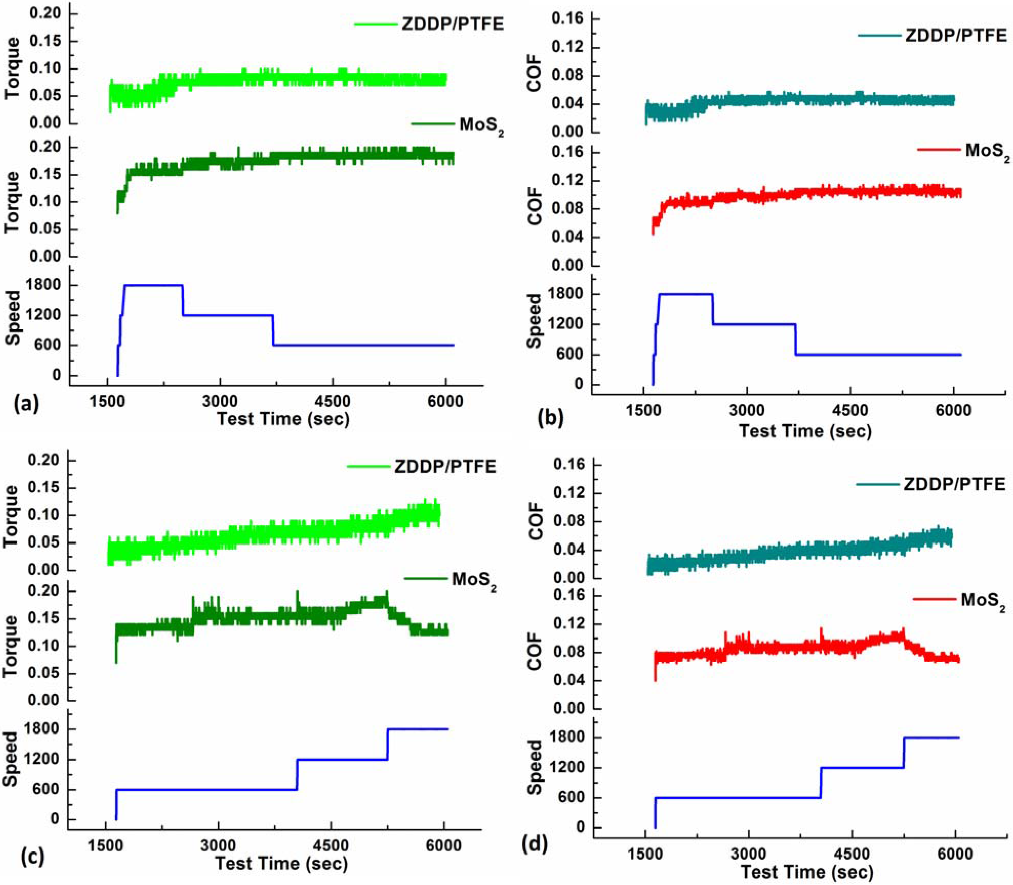
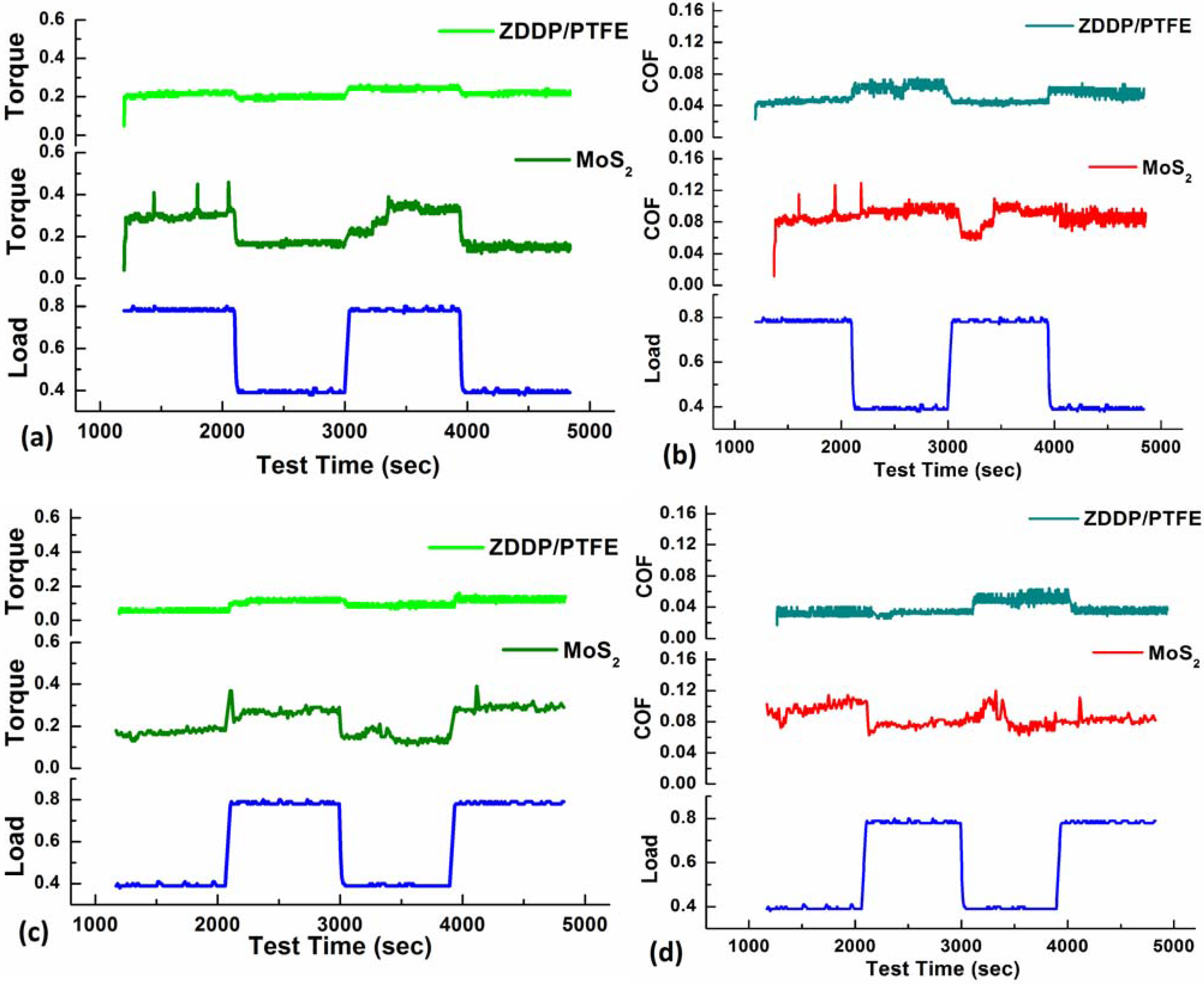
3.4. Torque and Coefficient of Friction (COF)

The torque and COF were obtained from the tests conducted using the four-ball tribometer. Torque values are absolute whereas COF values are derived and hence were calculated using the procedure as described in ASTM D5183-05 standard [25]. Figure 3, Figure 4 and Figure 5 represent the torque and COF values for both the blends used in the study and for all six tests. The load values plotted are in kilo Newtons (kN), the frequency or the sliding speed values are in rotations per minute (rpm) and the torque values generated are in Newton-meters (Nm).
Figure 3 compares the ramp-up and ramp-down conditions under cyclic loading that has a load step size of 15 min. The load and torque values are plotted in kN and Nm respectively. Figure 3a,c compare the torque responses for the grease with MoS2 particles and grease with a mixture of ZDDP and F-PTFE respectively and Figure 3b,d compare the COF values of the blends for corresponding loading conditions. Figure 3a,b correspond to Test 1 and the ramp-down conditions while Figure 3c,d correspond to Test 3 and the ramp-up conditions. These tests consist of four load steps of 15 min, each consisting of 18,000 cycles that result in a total of 72,000 cycles for the test. It is clear from the torque and COF plots in all cases that the ZDDP + F-PTFE grease results in a relatively smooth torque and friction coefficient as well as lower absolute values when compared to the MoS2 grease.
Figure 4 compares the ramp-up and ramp-down conditions under cyclic loading conditions that have a load step size of 7.5 min. Figure 4a,c compare the torque responses for the grease with MoS2 and the grease with a mixture of ZDDP + F-PTFE and the Figure 4b,d compare the COF values of the blends for the corresponding loading conditions. Figure 4a,b correspond to Test 2 and the ramp-down conditions while Figure 4c,d correspond to Test 4 and the ramp-up conditions. These tests consist of eight load steps of 7.5 min, each consisting of 9000 cycles that result in a total of 72,000 cycles. When the torque and COF obtained from tests with load step sizes of 7.5 min is compared to the torque and COF obtained from the tests with 15 min step size, it can be seen that larger the number of load variations the greater is the variation in the COF. In addition, the COF obtained from MoS2 grease has more excursions than the COF obtained from ZDDP/F-PTFE grease.
Figure 3. (a,c) Torque (Nm) and (b,d) COF values for cyclic loading conditions with a load step size of 15 min.
Lubricants 03 00687 g003
Figure 5 compares the ramp-up and ramp-down conditions under cyclic frequency conditions that have a frequency step size of 600 rpm. Under the ramp-down conditions the frequency or the sliding speed is decreased from 1800 rpm to 600 rpm in steps of 600 rpm whereas, for ramp-up conditions, the frequency or the sliding speed is increased from 600 rpm to 1800 rpm in steps of 600 rpm. The speed and torque values are plotted in the units of rpm and Nm, respectively. Figure 5a,c compare the torque responses for the grease with MoS2 and the grease with a mixture of ZDDP + F-PTFE and the Figure 5b,d compare the COF values of the blends for the corresponding frequency conditions. Figure 5a,b corresponds to Test 5 and the ramp-down conditions while Figure 5c,d correspond to Test 6 and the ramp-up conditions. These tests consist of three frequency steps, each consisting of 24,000 cycles that result in a total of 72,000 cycles. The torque and COF variations in the case of cyclic frequency conditions are almost flat in both the blends. It is also observed that, during the ramp-up tests at a frequency step of 1800 rpm, there is a slight drop in the COF for both the blends at higher rpm as the separation between the surfaces is increased reducing the asperity contacts thereby reducing the torque and friction coefficient.
Figure 4. (a,c) Torque (Nm) and (b,d) COF values for cyclic loading conditions with a load step size of 7.5 min.
Lubricants 03 00687 g004
Figure 5. (a,c) Torque (Nm) and (b,d) COF values for cyclic frequency conditions with a frequency step size of 600 rpm.
Lubricants 03 00687 g005

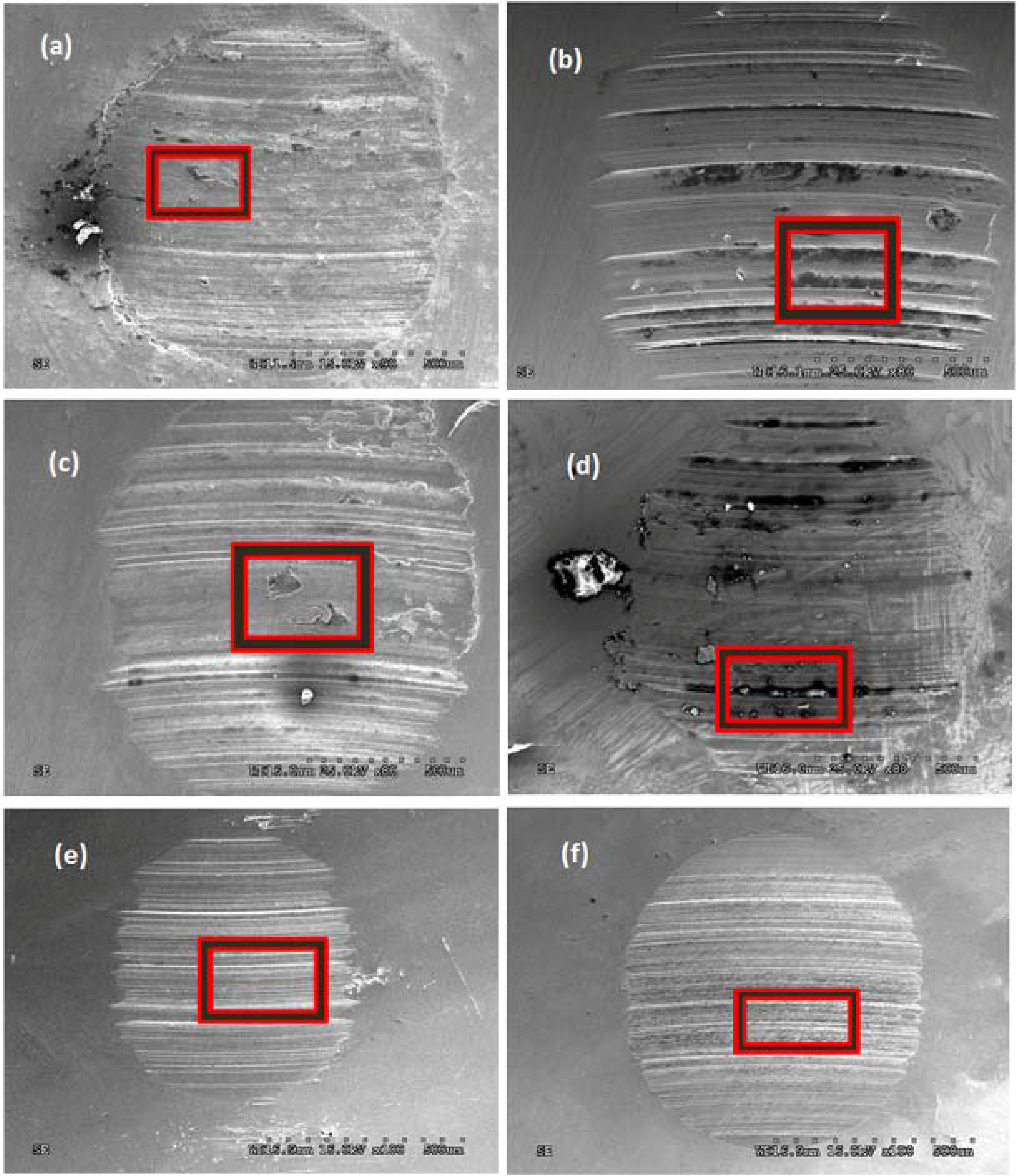
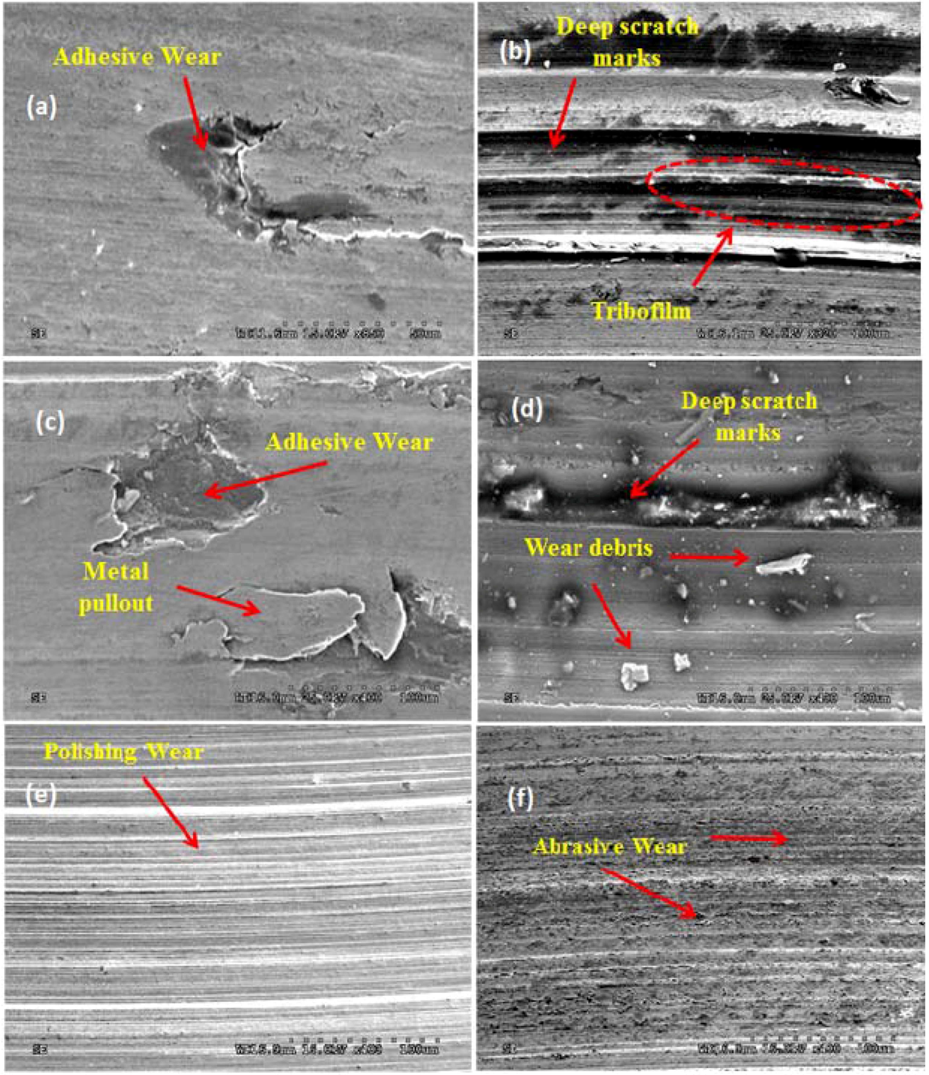
3.5. Scanning Electron Microscopic Analysis of the Wear Surface

The SEM images for the wear surfaces were obtained for all the tests and both the blends containing MoS2 particles and a combination of ZDDP and F-PTFE. Figure 6 represents the low magnification SEM images for the wear surface obtained from grease containing MoS2. The Figure 6a–d correspond to cyclic loading conditions and the Figure 6e,f represent the cyclic frequency conditions. Figure 7a–f represents the high magnification secondary electron images for the wear surface shown in Figure 6a–f obtained from grease with MoS2. These images represent the area enclosed in the boxes as shown in Figure 6. A comparison between the images taken at cyclic loading and cyclic frequency shows a larger amount of wear for the cyclic loading tests as compared to the cyclic frequency tests. There is an excessive amount of abrasive wear and metal removal for cyclic loading tests as compared to polishing wear in the cyclic frequency tests.
Figure 6. Low magnification SEM images for grease containing MoS2 particles wherein (af) represent the images from Test 1 to Test 6.
Lubricants 03 00687 g006
Figure 7. High magnification SEM images for grease containing MoS2 particles wherein (af) represent the images from Test 1 to Test 6.
Lubricants 03 00687 g007
Figure 8 represents the low magnification secondary electron images for the wear surface obtained from the grease containing a combination of ZDDP and F-PTFE. The representative boxes show the area of interest that is further magnified to study the wear mechanism. The images Figure 8a–d correspond to cyclic loading conditions and the images Figure 8e,f represent the cyclic frequency conditions. Analogous to Figure 6 for grease containing MoS2, it is evident that the images for cyclic frequency conditions show smaller amounts of wear and abrasion as compared to the cyclic loading conditions. The secondary electron images in Figure 9a–f represent the high magnification images of the corresponding wear surfaces in Figure 8a–f. The images indicate that abrasive wear mechanisms, metal pull-out are dominant mechanisms in cyclic loading conditions whereas polishing wear appears to be evident in cyclic frequency conditions. There is a presence of tribofilms on the wear surface that protects the surface from further wear and abrasion resulting in smaller wear scar diameters in grease with ZDDP and F-PTFE.
Figure 8. Low magnification SEM images for grease containing ZDDP and F-PTFE wherein (af) represent the images from Test 1 to Test 6.
Lubricants 03 00687 g008
Figure 9. High magnification SEM images for grease containing ZDDP and F-PTFE wherein (af) represent the images from Test 1 to Test 6.
Lubricants 03 00687 g009

4. Discussion

The effect of particle morphology and the synergy between additive chemistries is examined in the context of cyclic loading and cyclic frequency conditions. The wear mechanisms and the nature of tribofilms formed on the wear surface and its role in protecting the surface from further abrasion are also discussed. A detailed account of the synergy between the functionalized PTFE and ZDDP is discussed as well.

4.1. Effect of Particle Morphology and Chemistry

The SEM images shown in Figure 1 compare the morphology of the MoS2 and F-PTFE particles. The major difference that is clearly seen is the sharp edges and corners present on the MoS2 particles and the curved or rounded edges on the F-PTFE particles. It has been shown in previous studies [18,23,24,26] that the abrasive nature of MoS2 particles at lower loads was responsible for an increased wear and friction coefficient. A comparison of the morphology of these particles in Figure 1a,b, shows a striking contrast, MoS2 particles have sharp edges while F-PTFE is spherical in nature and when MoS2 is not oriented in the direction of motion of the bearing could potentially result in abrasive wear. A recent study by Suresh et al. [18], has also established an upper limit of 3 wt.% of MoS2 beyond which there was a significant increase in wear at lower loads despite a benefit in the load bearing capacity.
Wear scar diameter in Figure 2a,b indicates that the grease containing ZDDP and F-PTFE yields lower wear scar diameters and COF as compared to the grease containing MoS2 particles. The corresponding error bars also represent lower variation in the distribution of WSD for grease with ZDDP and F-PTFE and higher repeatability. MoS2 has long been used as an EP additive and is well known for its load bearing capabilities. The MoS2 particles have to orient in the direction of shearing while passing through the interacting surfaces so that the layers get sheared which in-turn deposit on the surface forming a tribofilm that leads to an increase in the load-bearing capability while protecting the surface from further abrasion [27,28,29,30]. Several studies have proposed different friction mechanisms for MoS2 particles like intrinsic cleavage mechanism, adsorption mechanism theory, and inter-crystallite slip mechanism which explain the effectiveness of MoS2 as an EP additive [31,32,33]. However, if these particles have sharp edges and not oriented in the direction of shearing then it leads to an increased wear and friction at lower loads [24]. MoS2 functions by shearing of the lamellar structure under applied loads, these layers are physically deposited on the wear surface forming a sacrificial tribofilm protecting the surface from wear and abrasion [27,28]. On the other hand if F-PTFE is used alone, a thin layer of F-PTFE adheres to the interacting surface due to a physical reaction between the F-PTFE and the metal substrate and F-PTFE chain might fracture under applied loads and temperatures inducing chemical reactions on the surface forming protective tribofilms [19]. F-PTFE also reacts synergistically with ZDDP that helps improve the antiwear (AW) and extreme pressure (EP) properties [18,20].

4.2. Effect of Cyclic Loading Conditions

In the current study, an effort is made to understand the effects of varying loads and different step times on the wear and friction performance of the greases containing MoS2 particles and a combination of ZDDP and F-ZDDP. Cyclic loading conditions correspond to the Tests 1 to 4 detailed in Table 2 and are further classified into ramp-up and ramp-down tests with load step sizes of 15 min and 7.5 min each. Tests 1 and 2 are ramp-down tests wherein the test begins at a higher load of 80 kg and terminates at a lower load of 40 kg, while Tests 3 and 4 are ramp-up tests wherein the test begins at a lower load of 40 kg and terminates at a higher load of 80 kg.
Figure 2c represents the WSD the grease containing MoS2 particles and the grease containing ZDDP and F-PTFE. When the WSD for Tests 1 to 4 are compared for both the blends it can be clearly distinguished that the grease containing ZDDP/F-PTFE exhibits between 30% and 40% less wear compared to the grease containing MoS2 particles. When the error bars are compared it can be seen that there is a wider distribution of WSD and larger WSD from the MoS2 grease suggesting that the sharp edges and corners of the MoS2 particles were responsible for large amount of abrasive wear and material removal, on the other hand the grease containing ZDDP and F-PTFE has a lower WSD and a narrower distribution of the data that is attributed to the synergistic interaction between ZDDP and F-PTFE.
Comparing the torque and coefficient of friction (COF) from Figure 3 and Figure 4 it can be seen that grease containing ZDDP + F-PTFE has a low COF which does not vary much and does not exhibit excursions when compared to grease containing MoS2 particles. The sharp spikes that are visible in the torque and COF for all the tests of MoS2 grease correspond to the tribological events like abrasive wear, adhesive wear, metal pull-out, deep scratch marks, or deep grooves that occur on the wear surface. In addition for both the grease blends, in all the tests, there is a small surge in the torque and COF values when the load is changed from 40 kg to 80 kg. This particular trend is much more visible for MoS2 grease. The MoS2 particles present in between the interacting surfaces that are not oriented in the direction of shearing during an increase in the load from 40 kg to 80 kg tend to remove a larger amount of material than at lower loads.
It can also be seen that the torque and COF are inversely related for both the grease blends, upon increase in the load there is an increase in the torque but a decrease in the COF. The increase in torque is not proportional to the increase in the applied load resulting in a decrease in the COF. It has been reported by several studies [18,30,34,35], that the lower loads are insufficient for shearing of MoS2 particles thereby leading to an increase in the friction, however at higher loads the weak Van der Waals forces present in between the hexagonal Mo and S layers are overcome leading to shearing of the layers at the S-S interface. Temperature and moisture also play a significant effect on the lubricating properties of MoS2. The presence of moisture results in poor wear properties while its performance in dry air or in an inert environment containing argon gas is significantly better [36]. In a study on the role of moisture on wear characteristics of MoS2 by Gao et al. [37] it has been shown that the presence of moisture leads to softening of MoS2 particles resulting in a thinner film on the interacting surface thereby reducing its load-bearing capabilities and wear resistance. In the current study no attempt was made to control the environment and a normal laboratory environment with a relative humidity of approximately 30% was used in all tests.
On comparison with the tests in Figure 3 and Figure 4 with load steps of 15 min and 7.5 min respectively, it is observed that higher number of changes in the load per test leads to an increased amount of wear and COF. When the WSD for the Tests 2 and 4 are compared with the WSD for Tests 1 and 3 as shown in Figure 2, it suggests that the Tests 2 and 4 that have load step sizes of 7.5 min yield higher wear scar diameters. The cyclic loading tests with a load step size of 15 min exhibit a smoother distribution of torque and COF values as compared to the tests with load step size of 7.5 min. This is evidently seen for the grease with MoS2, on the other hand grease with ZDDP and F-PTFE there is a little variation in the torque and COF for tests with step sizes of 15 min and 7.5 min. For grease containing MoS2 particles, when Figure 3c is compared to Figure 3a and Figure 4c compared to Figure 4a, it is evident that ramp-up conditions that begin at a lower load and terminate at a higher load show a smoother variation in the torque and corresponding COF values, the lower loads result in the formation of a stable tribofilm on the interacting surface which limits the abrasion of the surface when the load is ramped up. However, in the case of ramp-down conditions where the tests begin at higher loads and terminate at lower loads, the MoS2 particles that pass through the interacting surfaces in a manner that are not oriented in the direction of shearing, result in a larger amount of wear and corresponding higher friction. In the case of grease containing ZDDP + F-PTFE, there is no significant difference in the smoothness of the torque and COF curves for ramp-up tests. However for ramp-down tests that begins at a higher load and terminate at a lower load, the step duration of the cyclic load influences the COF there is dependence of step time. The ramp-down tests with a load step size of 7.5 min yields a larger variation in friction as compared to the ramp-down tests with load step size of 15 min.
The distribution of coefficient of friction for grease containing MoS2 and grease containing ZDDP + F-PTFE are 0.07–0.15 and 0.022–0.04 respectively. There is about 70% reduction in the COF values for grease with ZDDP + F-PTFE as compared to grease containing MoS2 particles. This can be attributed to the chemistry of the additives and particle morphology, wherein most of the sharp edges and corners present on the MoS2 particles are responsible for higher wear and friction as compared to the much smoother and rounded edges of F-PTFE particles combined with their synergy with ZDDP.
Secondary electron images were taken to elucidate the wear mechanism after the end of the tests. Figure 6 and Figure 7 represent the low and high magnification SE images for grease containing MoS2 particles while Figure 8 and Figure 9 represent the SE images for the grease containing ZDDP and F-PTFE. In all cases the WSD for grease with ZDDP + F-PTFE is much smaller than the WSD for grease with MoS2. For grease with MoS2, on comparison of Figure 7a–d that correspond to cyclic loading conditions, exhibits evidence of abrasive wear, adhesive wear, metal pull-out, deep grooves, or scratch marks that come as a result of MoS2 particle edges that appear to be highly abrasive. Figure 7b,d correspond to the Tests 2 and 4 that have a load step size of 7.5 min and leading to higher number of variations in the load and leads to more abrasive wear, higher torque and COF, and a corresponding higher wear scar diameter as detailed in Figure 2c. There is strong evidence of formation of tribofilm on the wear surface in Figure 7b that is beneficial in terms of increasing the load bearing capabilities. The presence of wear debris in Figure 7d indicates signs of adhesive wear leading to cold weld of asperities on the wear surface. Figure 7a–c represents Tests 1 and 3 that have a load step size of 15 min. The wear surface exhibits abrasive wear accompanied with polishing wear. The Figure 9a–d represent the cyclic loading conditions from Tests 1 to 4 for grease with ZDDP and F-PTFE. There is no evidence showing ploughing grooves, deep scratch marks or adhesive wear on the wear track that is seen in the MoS2 grease and believed to be due to the formation of protective tribofilm on the wear surface due to the synergistic interaction in between ZDDP and F-PTFE. These sacrificial tribofilms are responsible for the reduction of WSD and COF. However, there is a presence of abrasive wear and polishing wear on the interacting surfaces. Small patches of tribofilm are also formed on the surface.

4.3. Effect of Cyclic Frequency Conditions

Cyclic frequency conditions correspond to the Tests 5 and 6 and can be further classified into ramp-down and ramp-up tests. These tests have a frequency step size of 600 rpm. Test 5 is a ramp-down test that begins at 1800 rpm and terminates at 600 rpm while Test 6 is a ramp-up test that begins at 600 rpm and terminates at 1800 rpm. Figure 2c represents that WSD for both the grease blends. On comparing the WSD for Tests 5 and 6, a difference of about 150 µm to 250 µm is seen in the WSD for the grease containing MoS2 and ZDDP + F-PTFE. The WSD distribution that is represented by the error bars for tests 5 and 6 shows minimal variation for grease with ZDDP and F-PTFE suggesting highly repeatable results.
Figure 5 is a plot of the torque and COF values for the ramp-up and ramp-down tests. At 1800 rpm the torque and COF values significantly drop for all grease with MoS2. In the case of grease containing ZDDP + F-PTFE, there is a drop in the torque and COF values at higher rpm in ramp-down tests, however, in ramp-up tests as shown in Figure 5c,d, it is seen that the torque and COF values increase with an increase in the rpm.
It is well known from the principles of boundary lubrication and the Stribeck curve that with an increase in the sliding speed or an increase in the fluid viscosity the separation between the opposing surfaces is increased resulting in a mixed or a hydrodynamic lubrication regime depending on the thickness of the lubricant layer which is present in between the interacting surfaces. When the separation between the surfaces is more than the height of asperities, it leads to a significant drop in the COF and wear of the surfaces as the asperities no longer touch each other which might have led to an abrasive or adhesive wear and the formation of wear debris that would increase the WSD [38,39,40,41,42]. During the ramp-down tests as indicated in the Figure 5a,b, it can be seen that the torque and COF values in the beginning of the tests are lower when the sliding speed is 1800 rpm and slowly rises or is constant towards the end of the test when the sliding speed is 600 rpm. With a reduction in the sliding speed the surfaces come closer to each other increasing the likelihood of asperity contact resulting in wear of the surface. During the ramp-up tests as shown in Figure 5c,d, it is observed that at 1800 rpm there is a sharp decrease in the torque and COF for the grease with MoS2.
Comparison of the secondary electron images of the wear track for the grease containing MoS2 and ZDDP + F-PTFE subjected to cyclic frequency tests indicates fewer signs of abrasive or adhesive wear in comparison to the cyclic load tests. Figure 6e,f as well as Figure 8e,f represent low magnification and Figure 7e,f and Figure 9e,f the corresponding high magnification secondary electron images of wear surfaces from MoS2 and ZDDP + F-PTFE grease respectively subjected to cyclic frequency tests. The topography of the wear surface shows prominent presence of polishing wear with little evidence of severe wear phenomenon occurring on the surface that were seen in the cyclic loading tests. The sharp edges and particles of MoS2 present in the MoS2 grease contribute to abrasive wear in certain areas as shown in Figure 7f, for grease containing ZDDP + F-PTFE, there is evidence of minor abrasive wear and tribofilm formation on the surface in the form of patches that protects the surface from further abrasion and wear.

4.4. Synergism in between ZDDP and F-PTFE

In the current study a functionalized fluoropolymer like PTFE that has a carboxylic functionality was used with an organothiophosphate like ZDDP to understand their behavior under spectrum loading conditions. There are a number of studies that suggest synergism in between ZDDP and F-PTFE. The fluoropolymer is surrounded by carboxylic acid functional groups which makes it more active when interacting with an organothiophosphate [18]. ZDDP functions as an AW additive by forming glassy tribofilm that is made up of short chain and long chain polyphosphates along with sulfides of Fe, Zn. The hard glassy films are formed when degradation compounds from tribochemical break-down of ZDDP react with the wear surface [43,44]. In some of the recent studies using ZDDP and a fluorinated compound usually a metal halide like FeF3, it was shown that the fluorinated compounds which act as fluorinating agents were able react with ZDDP leading to formation of a fluorinated version of ZDDP which was more reactive and effective as an antiwear agent [15,45,46,47]. In some of the recent studies, it has been shown that the decomposition temperature of ZDDP decreases in the presence of irradiated PTFE and metal halides like FeF3. Differential scanning calorimeter study was done on the combinations of ZDDP + F-PTFE and ZDDP + F-PTFE + FeF3; it was observed that, in the first case comprising of ZDDP/F-PTFE the ZDDP decomposes at 166 °C that is approximately 15 °C below its usual decomposition temperature (180 °C when a secondary ZDDP is heated at a rate of 5 °C/min in an inert environment) and in the second case consisting of ZDDP + F-PTFE + FeF3 the ZDDP decomposes at 155 °C that is about 25 °C below the usual decomposition temperature. In addition, an extra endotherm present at 170 °C where ZDDP + F-PTFE were used, suggests the formation of a new reaction product in the presence of a functionalized fluoropolymer that was shown to be beneficial in forming protective tribofilms.
In earlier studies it was suggested that the reaction mixture consisting of ZDDP + F-PTFE can be either reacted in or outside the lubricant environment and during or before the test [20,48,49,50]. The F-PTFE used in the present study contained about 40 to 6000 carbon atoms. The particle size of F-PTFE is very crucial in deciding the functionality and its degradation impacts the tribological performance. Irradiation leads to creation of electron acceptor groups on the PTFE particles that are dangling bonds thereby enhancing its adhesion to the surface. F-PTFE particles form a lubricious coating on the wear surface under temperature and pressure forming a tribofilm. Furthermore, the synergistic interaction of functionalized PTFE and ZDDP leads to a formation of a complex molecule on the reaction surface that comprises of ZDDP and its degradation products together with F-PTFE thereby having AW, EP, and anti-friction properties [48].

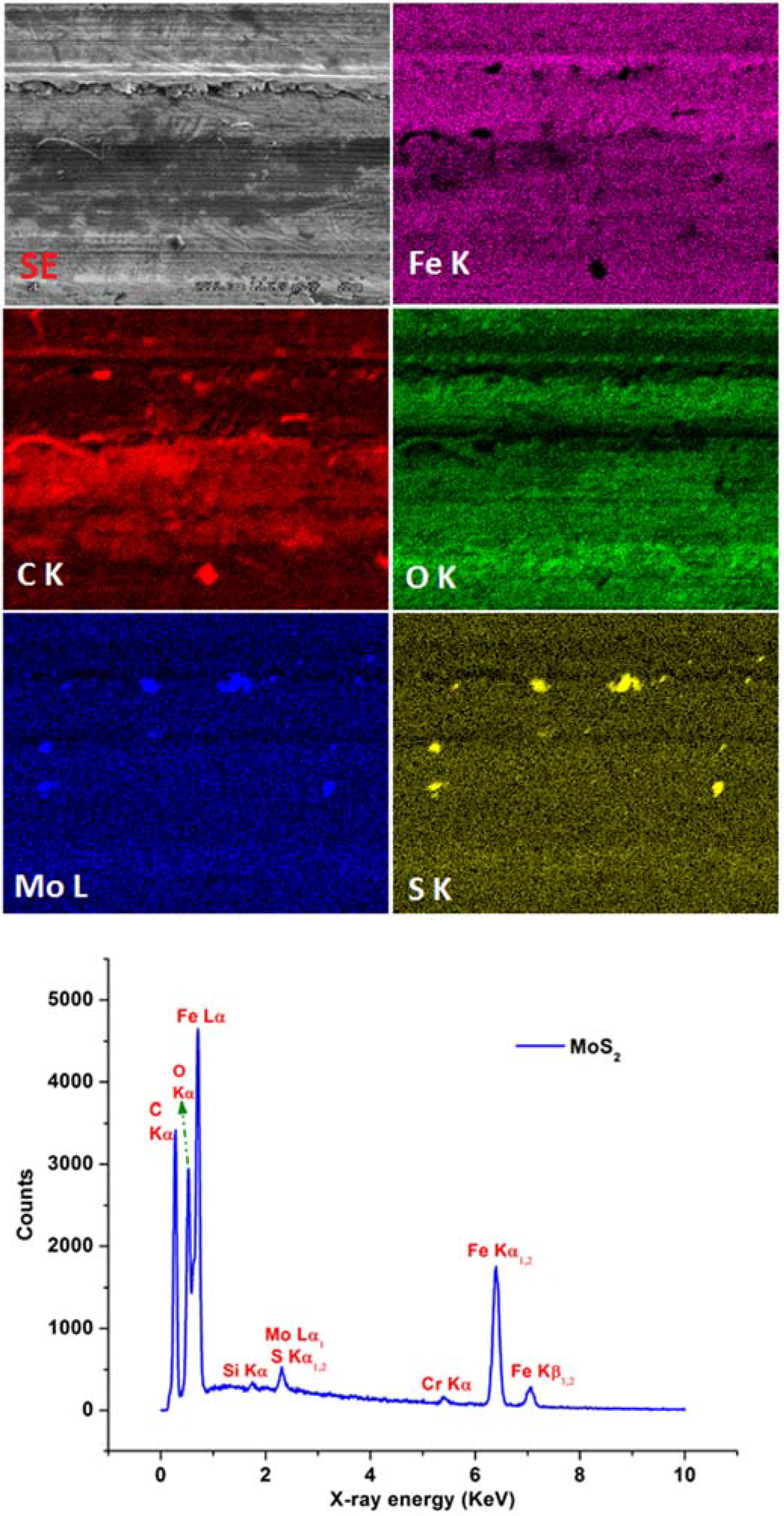
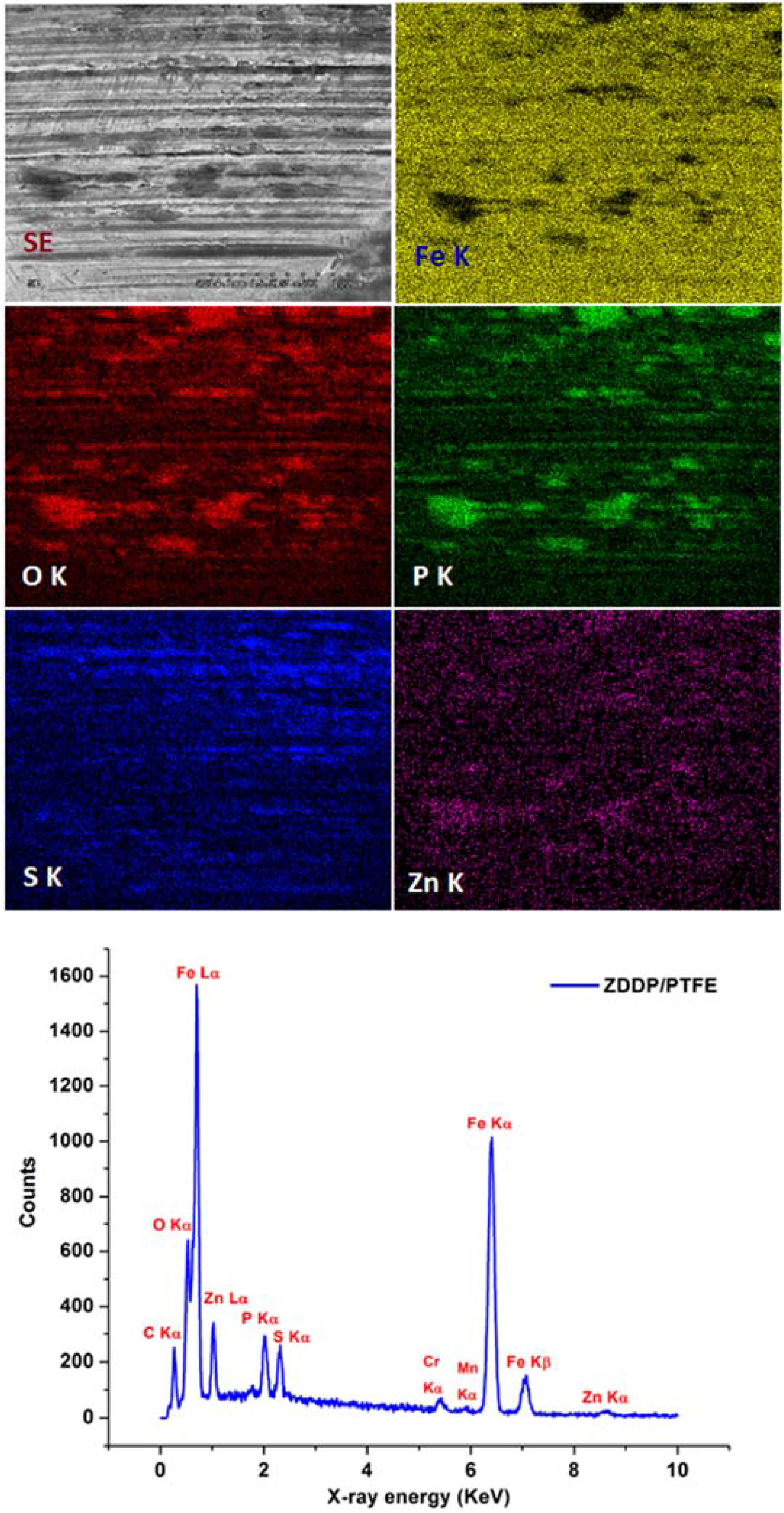
4.5. EDS Analysis of the Wear Surface

Figure 10 and Figure 11 show EDS elemental maps and spectra of the wear surface obtained from MoS2 and ZDDP/F-PTFE grease; Elemental maps were collected for Mo, S, C, O, P, Zn, and Fe. The bright patchy regions visible on Mo and S maps in Figure 10 strongly suggest the formation of MoS2 tribofilms. The lamellar structure of MoS2 is sheared and is physically deposited on the wear surface thereby increasing the load bearing capability and reducing abrasion. On comparing the bright patches that run across from end to end in the Mo, S, Fe, and O maps in Figure 10 indicate the likely formation of compounds like MoSO4, Fe3O4, and MoO3 on the surface. These oxidation products which form in the presence of oxygen are highly abrasive and tend to increase wear on the surface once they are removed from the surface. Dark regions on the Fe map indicate a thick layer of tribofilm in the region. The frictional heat produced by the collision of opposing asperities causes the oxides formed on the metal surface to be scraped off and the reaction or the deposition products (formed by chemisorption or physisorption of the additives), react with the metal surface to form an “Antiwear or EP” tribofilm. These tribofilms can be sheared more easily than the underlying metal, yield more readily during sliding than the substrate, and serve as an effective lubricant under high contact loading conditions.
Figure 10. EDS elemental maps and spectra from the wear surface obtained using grease containing MoS2 particles showing the presence of Mo, S, C, O, and Fe. The test conditions conformed to ASTM D2266.
Lubricants 03 00687 g010
The bright regions on C map in Figure 10 are considered to be degraded and polymerized base grease component. It was thought to be a chemisorbed layer as it is visible even after multiple washings with hexane and ultrasonication. From the EDS spectra in Figure 10, it can be clearly seen that the strongest signal arises from Fe Lα and Kα. The Cr and Si signals originate from the E52100 steel alloy as they are some of the alloying elements in the steel. There is a strong signal from C and O Kα that comes from degraded products, oxides, and as alloying elements in the E52100 steel. The signals from Mo L-edge and S K-edge lie very close to each other due to which they are almost inseparable. Since EDS is a qualitative technique and the intensities are displayed relative to each other, the signals from Mo and S appear low when compared to the signals obtained from Fe, O, and C.
Figure 11 is the EDS spectra for Blend 2 grease containing ZDDP + F-PTFE. The patches in O Kα and P Kα suggest the formation of long and short chain poly- and pyro-phosphates in the tribofilms whereas the patchy regions on the S Kα suggest the formation of sulfates and sulfides of Iron and Zinc. Similar to the data obtained from MoS2 grease, the dark regions on Fe Kα map point out the presence of dense regions of tribofilms on the wear surface. EDS spectra shows strong signals originating from the Kα and Lα of Fe, Kα of O and C. Signals from Kα of Cr and Mn are detected as they form the alloying elements in E52100 steel. Strong intensity peaks are seen from Kα spectra of P, S, and Kα and Lα of Zn which arise from the dense layers of tribofilm formed on the interacting surfaces.
Figure 11. EDS elemental maps and spectra from the wear surface obtained using grease containing ZDDP/F-PTFE showing the presence of Fe, O, P, S, and Zn. The test conditions conformed to ASTM D2266.
Lubricants 03 00687 g011

5. Conclusions

The current study was focused on developing an understanding of the role of spectrum loading conditions on the mechanism of wear and friction in greases that contain MoS2 and combinations of F-PTFE + ZDDP. Some of the conclusions drawn are:
  • Due to the morphology of the MoS2 particles with sharp edges, they behave as a pro-abrasive agent at lower loads that are not sufficient to overcome Van der Waals forces present at the S-S layer in the MoS2 structure that is responsible for shearing of lamellar layers forming a tribofilm on the wear surface.
  • The morphology of the MoS2 and F-PTFE particles has a significant effect on the wear and frictional performance of the formulated greases under spectrum loading conditions. F-PTFE particles owing to their rounded and curved edges combined with their synergy with ZDDP yield much lower wear scar diameters and COF values when compared to the grease containing MoS2 particles.
  • Under cyclic loading conditions where the sliding speed or the rpm of the opposing surfaces is fixed, higher number of load changes leads to higher wear and abrasion of the surface. The results obtained for tests with load steps of 7.5 min exhibit higher amount of wear and COF as compared to the tests with load steps of 15 min.
  • Cyclic frequency conditions where loads are maintained constant do not show a significant change in the wear and friction data for both the grease containing MoS2 particles and ZDDP + F-PTFE under ramp-up and ramp-down conditions respectively.
  • Under cyclic loading conditions for MoS2 grease, the ramp down tests exhibit relatively higher wear and COF values as compared to the ramp-up tests. A protective tribofilm is formed on the wear surface initially at lower loads in the ramp-up tests that protects the wear surface from wear and abrasion at higher loads. For grease with a mixture of ZDDP + F-PTFE there is no significant variation in the wear and COF for ramp-up and ramp-down tests.
  • Superior AW performance of the grease with ZDDP + F-PTFE is attributed to the synergistic interaction between a fluoropolymer like F-PTFE that is functionalized with an organothiophosphate like ZDDP. The fluoropolymer helps in the formation of a protective tribofilm on the wear surface leading to decrease in wear.
  • EDS elemental maps and spectra suggest the fact that MoS2 tribofilms are formed by physical and chemical adsorption of MoS2 layers that shear off from the lamellar structure and deposit on the wear surface protecting the surface while increasing the load bearing capability. EDS data for the ZDDP + F-PTFE wear surfaces indicates the presence of phosphate of Fe and Zn as well as sulfides and sulfates of Fe and Zn in the tribofilms.

Author Contributions

Sujay Bagi conducted all the experiments. Sujay Bagi and Pranesh B. Aswath contributed equally towards the interpretation, analysis and writing of the manuscript.

Conflicts of Interest

The authors declare no conflict of interest.

References

  1. Rudnick, L.R. Lubricant Additives: Chemistry and Applications; CRC Press: Boca Raton, FL, USA, 2009. [Google Scholar]
  2. Mas, R.; Magnin, A. Rheology of colloidal suspensions-case of lubricating greases. J. Rheol. 1994, 38, 889–908. [Google Scholar] [CrossRef]
  3. Hussey, G. Alteration of grease characteristics with new generation polymers. NLGI Spokesm. 1987, 51, 175–181. [Google Scholar]
  4. Rizvi, S.Q.A. Comprehensive Review of Lubricant Chemistry, Technology, Selection, and Design; ASTM International: West Conshohocken, PA, USA, 2009. [Google Scholar]
  5. Antony, J.P.; Mittal, B.D.; Naithani, K.P.; Misra, A.K.; Bhatnagar, A.K. Antiwear/extreme pressure performance of graphite and molybdenum disulphide combinations in lubricating greases. Wear 1994, 174, 33–37. [Google Scholar] [CrossRef]
  6. Srivastava, R.; Mehrotra, A.; Sinha, B.; Agnihotri, R.K. Graphite and Molybdenum Disulphide Lubricants Performance in Relation to Base Fluids. In Proceedings of the 5th International Colloquium on Additives for Lubricants and Operational Fluids, Esslingen, Germany, January 1986; pp. 6.1–6.10.
  7. Bartz, W. Solid lubricant additives—Effect of concentration and other additives on anti-wear performance. Wear 1971, 17, 421–432. [Google Scholar] [CrossRef]
  8. Bartz, W.; Holinski, R.; Xu, J. Wear life and frictional behavior of bonded solid lubricants. Lubr. Eng. 1986, 42, 762–769. [Google Scholar]
  9. Fischer, F.G.; Corn, A.D.; Huber, R.G. Graphite and Molybdenum disulfide synergism. NLGI Spokesm. 1982, 6, 190. [Google Scholar]
  10. Spikes, H.A. The history and mechanisms of ZDDP. Trib. Lett. 2004, 17, 469–489. [Google Scholar] [CrossRef]
  11. Nicholls, M.A.; Norton, P.R.; Bancroft, G.M.; Kasrai, M.; Do, T.; Frazer, B.H.; de Stasio, G. Nanometer Scale Chemomechanical Characterization of Antiwear Films. Tribol Lett. 2004, 17, 205–216. [Google Scholar] [CrossRef]
  12. Mosey, N.J.; Woo, T.K.; Müser, M.H. Mechanism of wear inhibition by ZDDP lubricant additives—Insights from molecular scale simulations. Am. Chem. Soc. Div. Pet. Chem. Prepr. 2005, 50, 332–335. [Google Scholar]
  13. Nicholls, M.A.; Do, T.; Norton, P.R.; Kasrai, M.; Bancroft, G.M. Review of the lubrication of metallic surfaces by zinc dialkyl-dithiophosphates. Tribol. Int. 2005, 38, 15–39. [Google Scholar] [CrossRef]
  14. Mourhatch, R.; Aswath, P.B. Nanoscale Properties of Tribofilms formed with Zinc Dialkyl Dithiophosphate (ZDDP) under Extreme Pressure Condition. J. Nanosci. Nanotechnol. 2008, 9, 2682–2691. [Google Scholar] [CrossRef]
  15. Mourhatch, R.; Aswath, P.B. Tribological behavior and nature of tribofilms generated from fluorinated ZDDP in comparison to ZDDP under extreme pressure conditions—Part 1: Structure and chemistry of tribofilms. Tribol. Int. 2011, 44, 187–200. [Google Scholar] [CrossRef]
  16. Kim, B.; Mourhatch, R.; Aswath, P.B. Properties of tribofilms formed with ashless dithiophosphate and zinc dialkyl dithiophosphate under extreme pressure conditions. Wear 2010, 268, 579–591. [Google Scholar] [CrossRef]
  17. Aswath, P.B.; Mourhatch, R.; Patel, K.; Munot, S.; Somayaji, A.; Elsenbaumer, R.L. A Design of Experiments Approach to Develop a Better Grease. NLGI Spokesm. (Natl. Lubr. Grease Inst.) 2007, 71, 8–16. [Google Scholar]
  18. Suresh, A.; Mourhatch, R.; Aswath, P. Effect of Test Parameters on the Four-ball Wear and Weld Performance of Greases with MoS2 and without MoS2 as EP Additive. NLGI Spokesm. (Natl. Lubr. Grease Inst.) 2009, 73, 24–35. [Google Scholar]
  19. Stolarski, T. Remarks on the wear of a journal bearing lubricated by a grease containing a powdered PTFE additive. Tribol. Int. 1976, 9, 161–163. [Google Scholar] [CrossRef]
  20. Aswath, P.B.; Shaub, H.; Mourhatch, R.; Patel, K.; Owen, D.; Elsenbaumer, R.L. High Performance Lubricants and Lubricant Additives for Crankcase Oils, Greases, Gear Oils and Transmission Oils. U.S. Patent 8227389, 24 July 2012. [Google Scholar]
  21. Stolarski, T.; Olszewski, O. An Experimental Study of the Frictional Mechanism in a Journal Bearing Lubricated with Grease Containing Powdered PTFE. Wear 1976, 39, 377–387. [Google Scholar] [CrossRef]
  22. Akdogan, G.; Stolarski, T.A.; Tobe, S. Wear of metal/PTFE coatings in rolling line contact. J. Mater. Sci. 2002, 37, 5013–5019. [Google Scholar] [CrossRef]
  23. Suresh, A. Synergistic and Antagonistic Effect of Sulfur-Based Additives on the Performance of Greases with ZDDP and PTFE. M.S. Thesis, The University of Texas, Arlington, TX, USA, 2009. [Google Scholar]
  24. Bagi, S.D.; Aswath, P.B. Role of MoS2 Morphology on Wear and Friction Under Spectrum Loading Conditions. Lubr. Sci. 2015, 27, 429–449. [Google Scholar] [CrossRef]
  25. ASTM International. ASTM D5183-05 (2011) Standard Test Method For Determination of Coefficient of Friction of Lubricants Using the Four-Ball Wear Test Machine. In Book of ASTM Standards; ASTM International: West Conshohocken, PA, USA, 2003. [Google Scholar]
  26. Aswath, P.B.; Patel, K.; Munot, S.; Elsenbaumer, R.L. Development of a High Performance Low Molybdenum Disulfide Grease. NLGI Spokesm. (Natl. Lubr. Grease Inst.) 2007, 70, 24–32. [Google Scholar]
  27. Mistry, A.; Bradbury, R. Investigation into the effect of molybdenum disulphide and graphite on the load carrying capacity of a grease. NLGI Spokesm. 2002, 66, 25–29. [Google Scholar]
  28. Risdon, T.J. Evaluation of MoS2 in Newer Grease Thickener Systems. NLGI Spokesm. 1986, 50, 211–214. [Google Scholar]
  29. Holinski, R.; Gänsheimer, J. A study of the lubricating mechanism of molybdenum disulfide. Wear 1972, 19, 329–342. [Google Scholar] [CrossRef]
  30. Winer, W.O. Molybdenum disulfide as a lubricant: A review of the fundamental knowledge. Wear 1967, 10, 422–452. [Google Scholar] [CrossRef]
  31. Lansdown, A. Molybdenum Disulphide Lubrication; Elsevier: Amsterdam, Holland, 1999. [Google Scholar]
  32. Dickinson, R.G.; Pauling, L. The crystal structure of molybdenite. J. Am. Chem. Soc. 1923, 45, 1466–1471. [Google Scholar] [CrossRef]
  33. Feng, I.M. Lubricating Properties of Molybdenum Disulfide. Lubr. Eng. 1952, 8, 285–288. [Google Scholar]
  34. Peterson, M.B. Friction and Wear Investigation of Molybdenum Disulfide I: Effect of Moisture; NASA Technical Report NACA-TN-3055; NASA: Cleveland, OH, USA, 1953.
  35. Boyd, J.; Robertson, B. The Friction Properties of Various Lubricants at High Pressure; ASME: New York, NY, USA, 1945; Volume 67. [Google Scholar]
  36. Fusaro, R.L. Effect of Substrate Surface Finish on the Lubrication and Failure Mechanisms of Molybdenum Disulfide Films; ASME Transactions: New York, NY, USA, 1982; Volume 25, pp. 141–156. [Google Scholar]
  37. Gao, C.; Bredell, L.; Kuhlmann-Wilsdorf, D.; Makel, D.D. Micromechanics of MoS2 lubrication. Wear 1993, 162–164 Pt A, 480–491. [Google Scholar] [CrossRef]
  38. Bhushan, B. Modern Tribology Handbook; CRC Press: Boca Raton, FL, USA, 2000; Volume 2. [Google Scholar]
  39. Anderson, W.; Wedeven, L.; Herguth, W.R. STLE-Basics of Lubrication. Available online: http://www.stle.org/resources/lubelearn/lubrication/default.aspx (accessed on 10 August 2012).
  40. Erdemir, A. Review of engineered tribological interfaces for improved boundary lubrication. Tribol. Int. 2005, 38, 249–256. [Google Scholar] [CrossRef]
  41. Komvopoulos, K.; Saka, N.; Suh, N. The mechanism of friction in boundary lubrication. J. Tribol. 1985, 107, 452–462. [Google Scholar] [CrossRef]
  42. Persson, B. Theory of friction and boundary lubrication. Phys. Rev. B 1993, 48, 18140. [Google Scholar] [CrossRef]
  43. Parekh, K.; Aswath, P.B.; Shaub, H.; Elsenbaumer, R.L. Low-Phosphorous Lubricant Additive. US Patent 8216982, 10 July 2012. [Google Scholar]
  44. Cann, P.; Spikes, H.A.; Cameron, A. Thick film formation by zinc dialkyldithiophosphates. ASLE Transactions 1983, 26, 48–52. [Google Scholar] [CrossRef]
  45. Parekh, K.; Chen, X.; Aswath, P.B. Synthesis of Fluorinated ZDDP Compounds. Tribol. Lett. 2009, 34, 141–153. [Google Scholar] [CrossRef]
  46. Somayaji, A.; Mourhatch, R.; Aswath, P.B. Nanoscale Properties of Tribofilms from ZDDP and Fluorinated ZDDP in the Presence and Absence of Antioxidants. J. Nanosci. Nanotechnol. 2007, 7, 4378–4390. [Google Scholar] [CrossRef] [PubMed]
  47. Mourhatch, R.; Parekh, K.; Aswath, P.B. A multi technique study of the tribological behavior and the tribofilms generated from fluorinated thiophosphate compounds in comparison to normal ZDDP. In Proceedings of the STLE/ASME International Joint Tribology Conference, San Antonio, USA, 23–25 October 2006. IJTC2006-12137.
  48. Aswath, P.B.; Shaub, H.; Mourhatch, R.; Patel, K.; Owen, D.P.; Eisenbaumer, R.L. High Performance Lubricant Additives. U.S. Patent 7754662 B2, 13 July 2010. [Google Scholar]
  49. Shaub, H.; Aswath, P.B.; Huq, M.Z. Engine Oil Additive. U.S. Patent 7074745 B2, 11 July 2006. [Google Scholar]
  50. Aswath, P.; Mourhatch, R.; Patel, K.; Monit, S.; Somayaji, A.; Elsenbaumer, R. A design of experiment approach to develop a better grease. In NLGI Spokesman-Including NLGI Annual Meeting-National Lubricating Grease Institute; National Lubricating Grease Institute: Kansas, MO, USA, 2007; Volume 71, pp. 8–16. [Google Scholar]

