
Experimental Performance Study of a High Speed Oil Lubricated Polymer Thrust Bearing

Abstract
:1. Introduction
2. Experimental Section
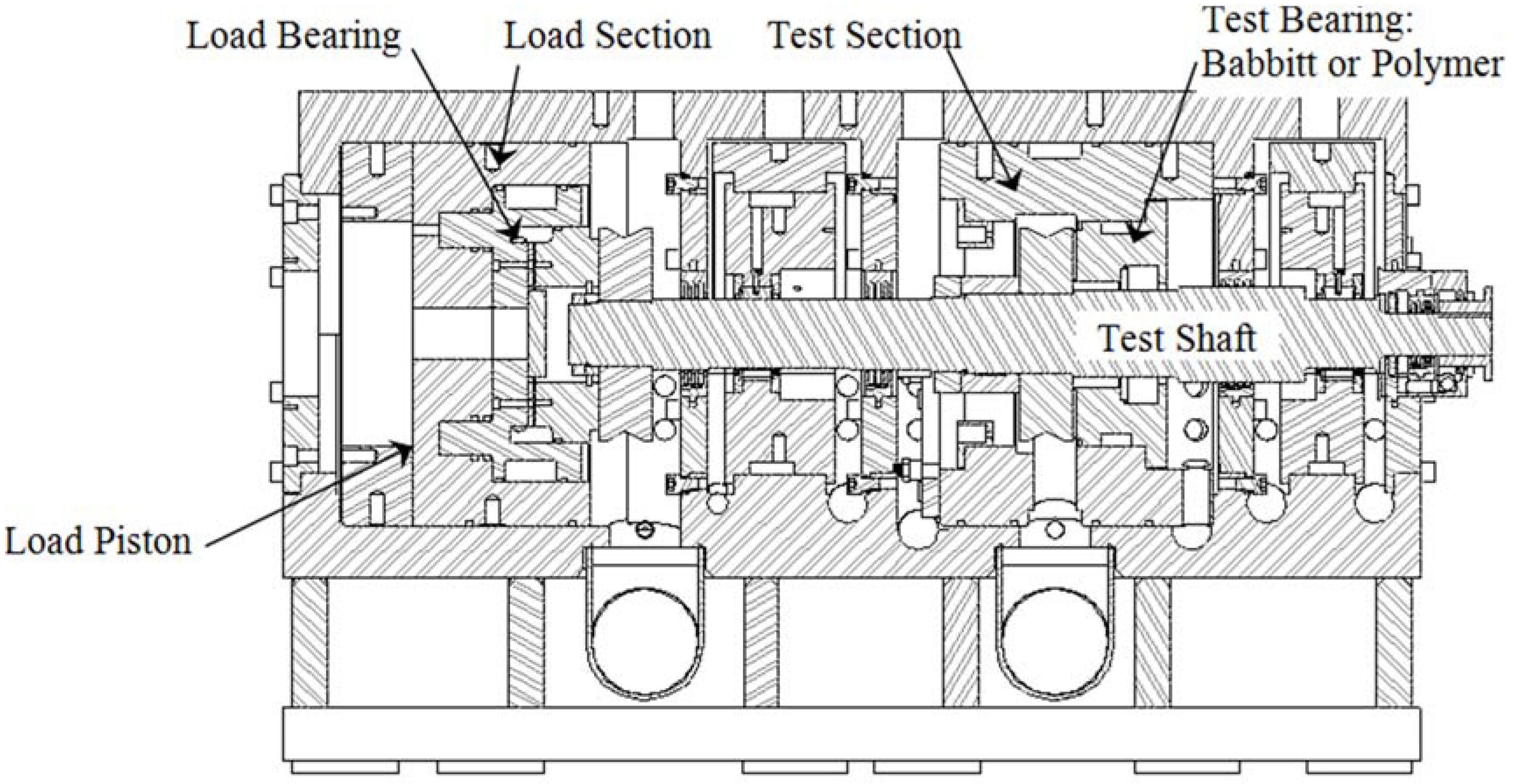
2.1. Test Platform
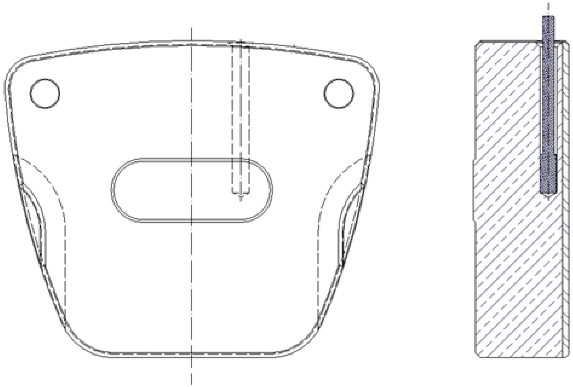
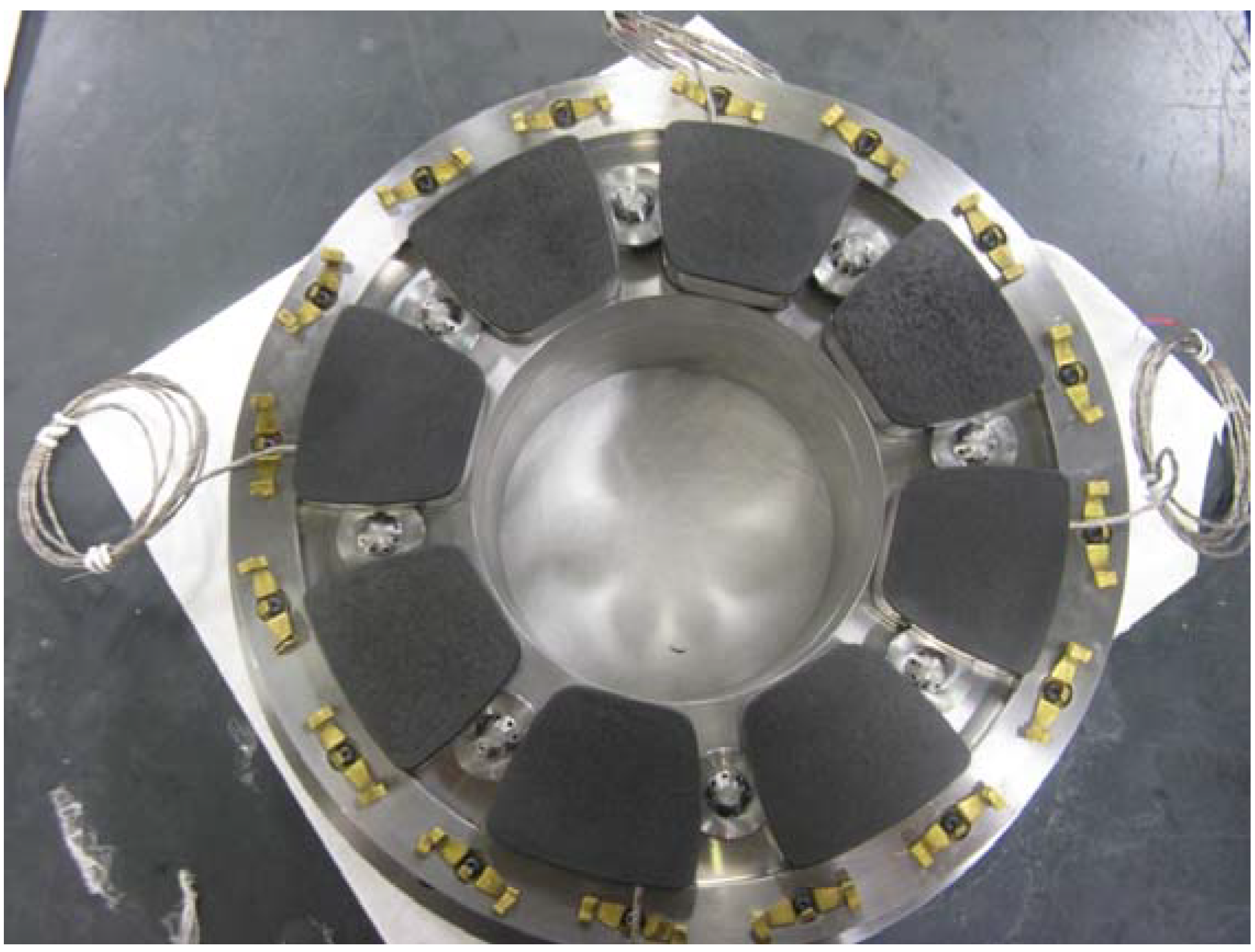
2.2. Bearing and Test Conditions


| Pad Bearing (Face) Material | Babbitt or PEEK |
|---|---|
| Pad backing material | Steel |
| Number of pad | 8 |
| Pad outside diameter, mm | 279 |
| Pad internal diameter, mm | 152 |
| Support System | 60% Offset |
| Equaling | Mechanical levers |
| Pad Size, mm | 62.5 |
| Pad aspect ratio | 1 |
| Rotational speed, rpm | 6000 1 and 11,000 |
| Sliding speed, m/s | 67.7, 124 |
| Lubricant | ISO VG 32 |
| Lubricant inlet temperature, °C | 48.9 |
| Lubricant flow rate, lpm | 125 |
2.3. Results


2.4. Results Discussion
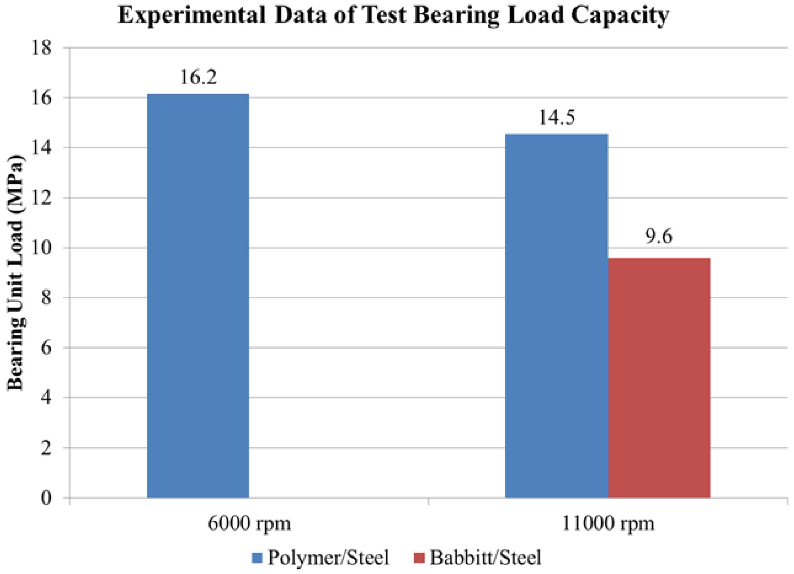
2.4.1. Load Capacity
| Properties | Babbitt | PEEK |
|---|---|---|
| Density, kg/m3 | 7400 | 1450 |
| Modulus, GPa | 52.4 | 12.5 |
| Tensile Strength (20 °C), MPa | 77 | 140 |
| Tensile Strength (100 °C), MPa | 40 | 106 |
| Metling Point, °C | 241 | 343 |
| Thermal Conductivity, W/mK | 55 | 0.87 |
| Specific Heat, kJ/kgK | 0.23 | 1.8 |
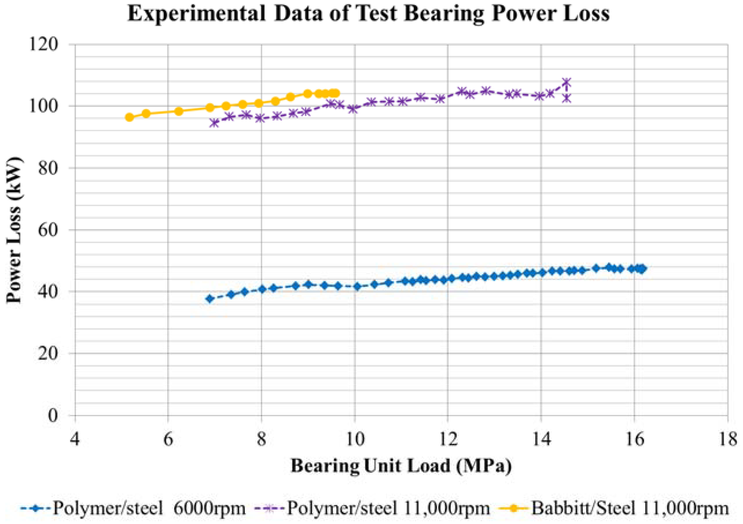
2.4.2. Power Loss
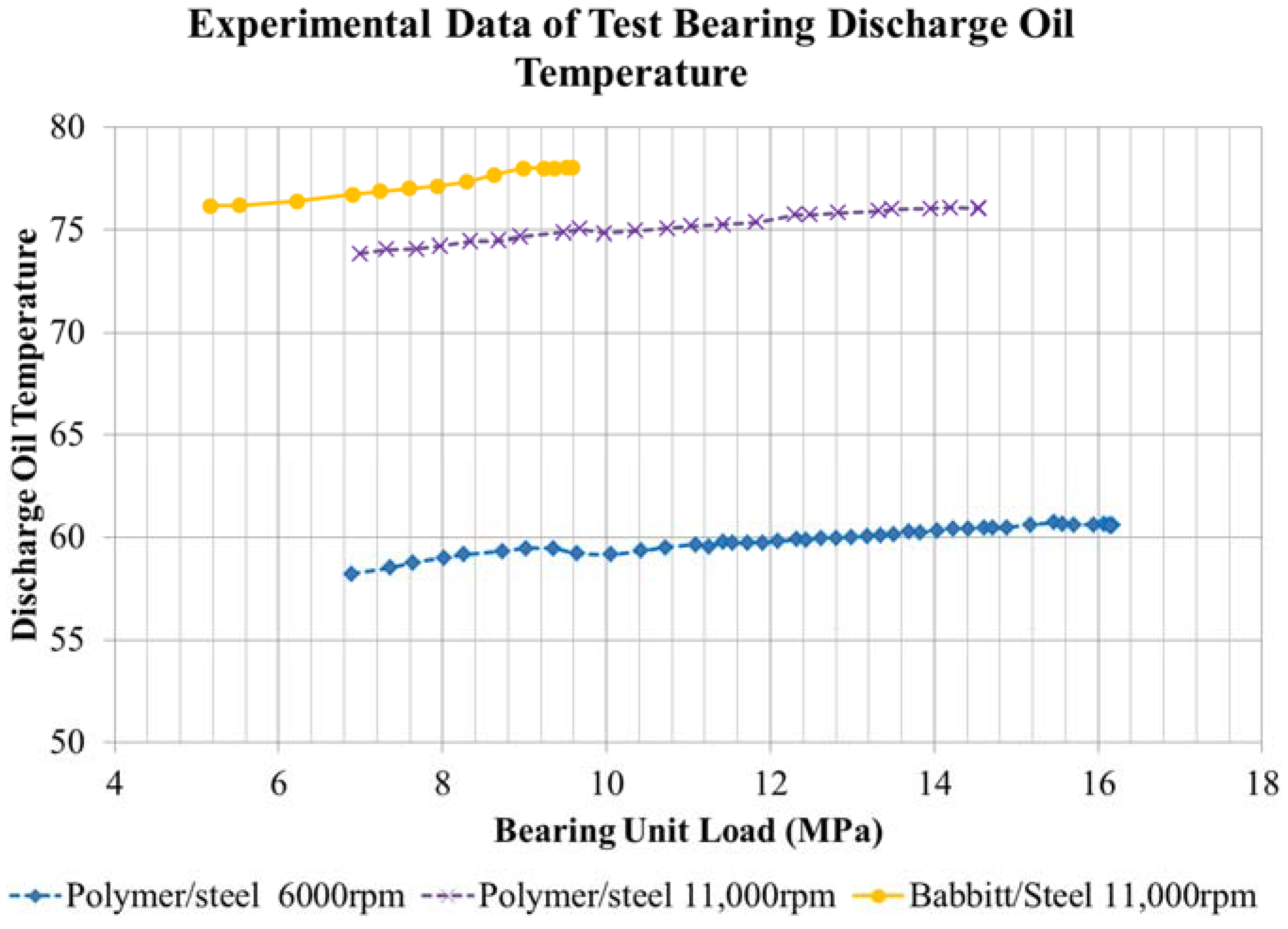
2.4.3. Temperature
3. Summary and Conclusions
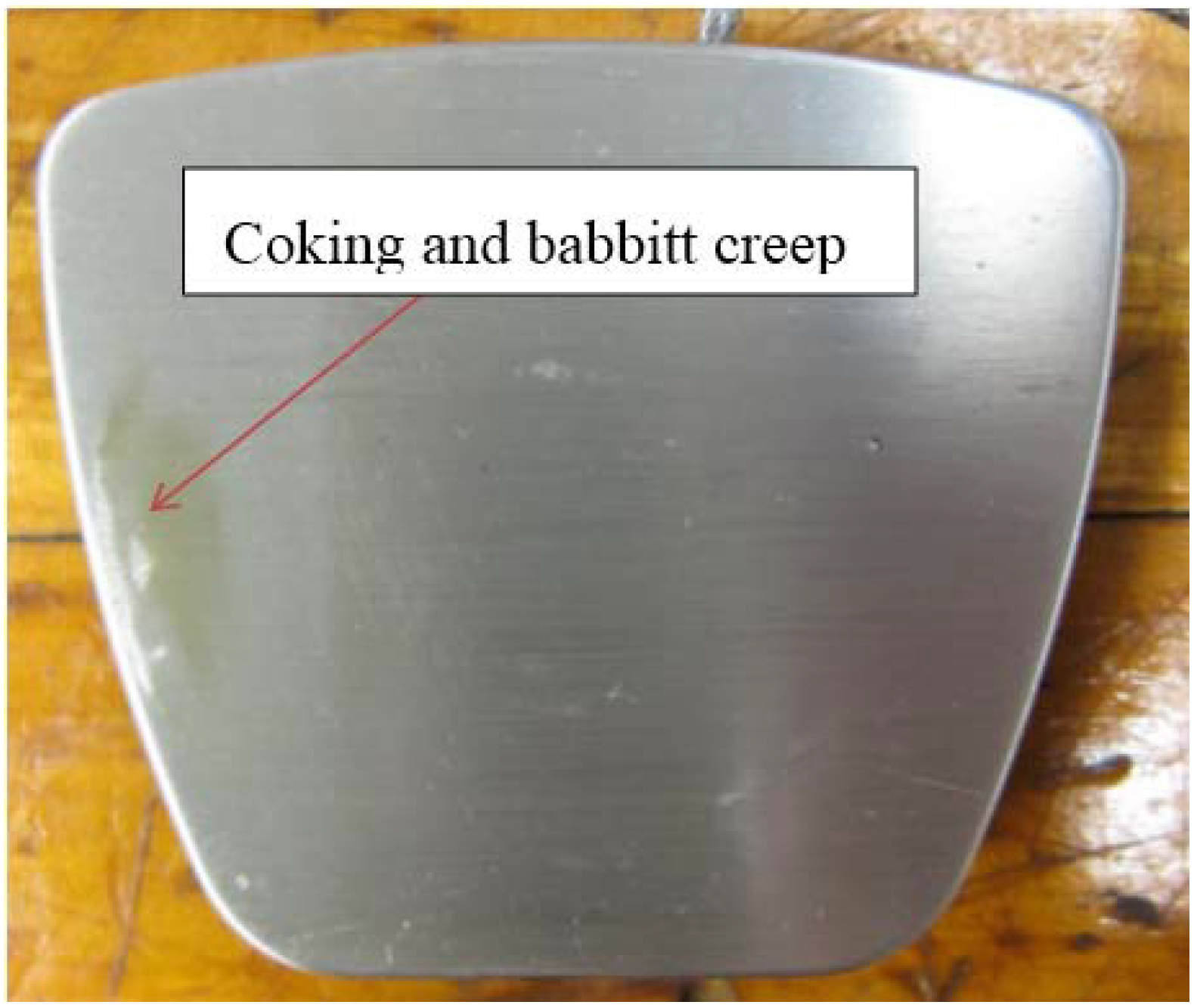
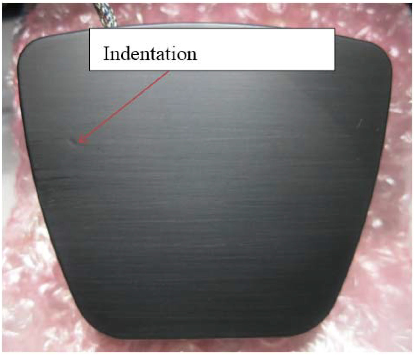
- A PEEK lined thrust bearing was successfully loaded to 14.5 MPa at 11,000 rpm and 16.2 MPa at 6000 rpm without significant indication of bearing distress. The same bearing with babbitt lined pads was only loaded to 9.6 MPa, as shown in Figure 4, before indication of distress. An increase of 50% in load for the PEEK lined thrust bearing was observed over the babbitt lined thrust bearing at 11,000 rpm. Taking advantage of PEEK bearing material, a smaller bearing with lower loss can be designed for the same load or the same bearing can be designed for higher loads by replacing the babbitt lining with a PEEK lining.
- The test thrust bearing with PEEK lined pads did not show significant power loss difference when compared to a bearing with babbitt lined pads of the same design and test conditions, as shown in Figure 8.
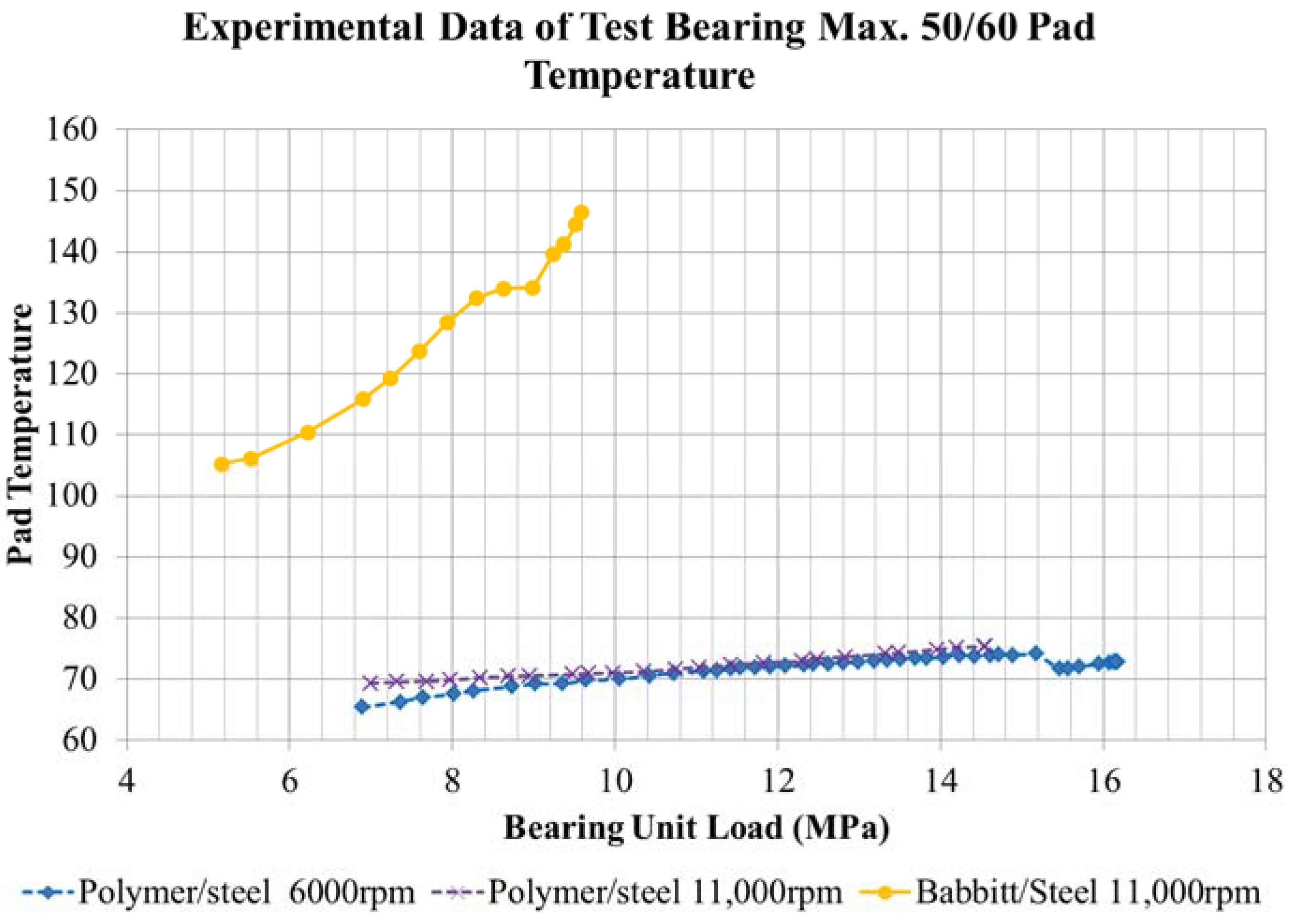
- With temperature sensors embedded in the pads 0.8 mm below the bond line, a small range of temperature variation over a wide load and speed range was observed with PEEK lined pads, as shown in Figure 10.
Acknowledgments
Author Contributions
Conflicts of Interest
References
- Nilsson, D.; Braham, P. Static/Dynamic friction and wear of some selected polymeric materials for conformal tribo-pairs under boundary lubrication conditions. Friction 2013, 1, 232–241. [Google Scholar] [CrossRef]
- Schroeder, R.; Torres, F.W.; Binder, C.; Klein, A.N.; de Mello, J.D.B. Failure mode in sliding wear of PEEK based composites. Wear 2013, 301, 717–726. [Google Scholar] [CrossRef]
- Lu, Z.P.; Friedrich, K. On sliding friction and wear of PEEK and its composites. Wear 1995, 181, 624–631. [Google Scholar] [CrossRef]
- Sınmazçelik, T.; Yilmaz, T. Thermal aging effects on mechanical and tribological performance of PEEK and short fiber reinforced PEEK composites. Mater. Des. 2007, 28, 641–648. [Google Scholar] [CrossRef]
- Friedrich, K.; Lu, Z.; Hager, A.M. Recent advances in polymer composites’ tribology. Wear 1995, 190, 139–144. [Google Scholar] [CrossRef]
- Quadrini, F.; Squeo, E.A. Injection molding of bushes made of tribological PEEK composites. Express Polym. Lett. 2007, 1, 817–823. [Google Scholar] [CrossRef]
- Pethybridge, G.; New, N. Plain bearing options for pumps. World Pumps 2002, 2002, 24–27. [Google Scholar] [CrossRef]
- Ricci, R.; Chatterton, S.; Pennacchi, P. Multiphysics modeling of a tilting pad thrust bearing with polymeric layered pads. In Proceedings of the 10th EDF/Pprime workshop, Futuroscope, France, 6–7 October 2011.
- Ettles, C.M.; Knox, R.T.; Ferguson, J.H.; Horner, D. Test results for PTFE-faced thrust pads, with direct comparison against Babbitt-faced pads and correlation with analysis. J. Tribol. 2003, 125, 814–823. [Google Scholar] [CrossRef]
- New, N.H. Experimental comparison of flooded, directed, and inlet orifice type of lubrication for a tilting pad thrust bearing. J. Tribol. 1974, 96, 22–26. [Google Scholar]
- Leopard, A.J. Tilting pad bearings-limits of operation. Lubr. Eng. 1976, 32, 637–644. [Google Scholar]
© 2015 by the authors; licensee MDPI, Basel, Switzerland. This article is an open access article distributed under the terms and conditions of the Creative Commons Attribution license (http://creativecommons.org/licenses/by/4.0/).
Share and Cite
Zhou, J.; Blair, B.; Argires, J.; Pitsch, D. Experimental Performance Study of a High Speed Oil Lubricated Polymer Thrust Bearing. Lubricants 2015, 3, 3-13. https://doi.org/10.3390/lubricants3010003
Zhou J, Blair B, Argires J, Pitsch D. Experimental Performance Study of a High Speed Oil Lubricated Polymer Thrust Bearing. Lubricants. 2015; 3(1):3-13. https://doi.org/10.3390/lubricants3010003
Chicago/Turabian StyleZhou, Jie, Barry Blair, John Argires, and Donald Pitsch. 2015. "Experimental Performance Study of a High Speed Oil Lubricated Polymer Thrust Bearing" Lubricants 3, no. 1: 3-13. https://doi.org/10.3390/lubricants3010003