Article

Sensitivity of Texture Evolution and Performance to Eccentricity, Misalignment, and Oil Supply in Journal Bearings with the Circumferential Oil Groove: An Adjoint-Based Optimization Study

1
Merchant Marine College, Shanghai Maritime University, Shanghai 201306, China
2
College of Mechanical and Electronic Engineering, Shanghai Jianqiao University, Shanghai 201306, China
3
School of Mechanical Engineering, University of Shanghai for Science and Technology, Shanghai 200093, China
*
Author to whom correspondence should be addressed.
Lubricants 2025, 13(11), 479; https://doi.org/10.3390/lubricants13110479
Submission received: 8 August 2025 / Revised: 10 October 2025 / Accepted: 28 October 2025 / Published: 29 October 2025

Abstract

Previous studies on improving journal bearing performance have predominantly overlooked the combined effects of the surface textures, circumferential oil grooves, eccentricity ratio, and misalignment. To address this gap, this study employed an adjoint -based optimization framework to optimize the LCC (load-carrying capacity) of journal bearings based on the mixed lubrication model. By incorporating the influence of the circumferential oil groove, the influences of the oil supply pressure, eccentricity ratio, and misalignment angle on the bearing performance and optimal texture evolution were studied. The results show that increased inlet oil pressure shortens textures and reduces the LCC enhancement, while misalignment boosts the absolute LCC but diminishes the relative benefit of textures. Bidirectionally optimized textures maintain robust performance under reverse rotation, with LCC improvements of 12.00 N at an eccentricity ratio (ER) of 0.8. In contrast, unidirectional textures may impair performance, with a reduction of up to –19.53 N. It is recommended to employ symmetric textures for bidirectional operation and to limit misalignment in order to retain the benefits of surface texturing. This research provides a practical foundation for designing high-performance journal bearings.

1. Introduction

Journal bearings play a crucial role in various mechanical systems, and enhancing their performance has been a continuous pursuit in the field of tribology [1]. Among the numerous factors influencing the performance of journal bearings, surface textures have emerged as a promising approach to improve lubrication efficiency and reduce friction. Jeon et al. [2] found that a journal bearing with a flexible structure can improve the lubrication performance in the misaligned condition. The rectangular-shaped flexible structure was more effective for increasing the minimum film thickness than the taper-shaped one for all tilting ratios. Cupillard et al. studied the performance of a textured journal bearing in terms of the friction coefficient [3]. They found that introducing deep dimples ( d h m i n > 1 ) in the zone of maximum pressure at a high eccentricity ratio would reduce the coefficient of friction, while at a low eccentricity ratio, shallow dimples ( d h m i n 1 ) located in the downstream of the maximum film had the same effect. Yu et al. studied the effects of flexibility and surface textures on the performance of a hydrodynamic finite-long journal bearing under a steady-state condition [4]. They found that textures placed near the zone of maximum pressure (without exceeding it) would improve the hydrodynamic performance. A higher texture density enhanced continuous hydrodynamic pressure accumulation. Wang et al. compared the performances of textured and non-textured high-speed journal bearings [5]. Their results showed that the influence of the texture on the bearing performance was changed with the eccentricity ratio. The LCC of a textured bearing becomes higher than that of an untextured bearing from an eccentricity ratio of 0.4. The maximum oil pressure of a textured bearing becomes lower than that of an untextured bearing when the eccentricity ratio was larger than 0.7. The effect of texturing in a partial-pad journal bearing was investigated by Morris et al. [6]. Through a series of experiments at operating conditions, improvements in the LCC were observed under certain conditions. A comprehensive computational finite volume multiphase fluid dynamics analysis was used to study the effect of indented surface textures on the microscale of the contact domain as well as the scale of the individual textures themselves. In this way, the influences of surface roughness and asperity interactions can be considered. Based on a transient mixed lubrication model, Gu et al. found that the impact of the texture on tribological performance transitions from beneficial to detrimental with the increase in deflection angles [7]. They found that a reduction of 7–8% in energy loss can be obtained when the grooved textures were introduced in the surfaces of the aligned bearing. However, the reduction in energy loss would be decreased when the misalignment was experienced. This highlights the need for texture optimization under specific conditions. Jin et al. used quadratic programming to study boundary slip effects [8]. Their study found that the full texture–slip combination can prominently reduce the LCC and the “forward-slip backward-texture” configuration can considerably improve the performance of journal bearings. Pradha et al. [9] applied a gray-based Taguchi optimization model to determine the optimal combination of bearing parameters influencing the LCC. Their study revealed that the bearing load was influenced by eccentricity, non-circularity, the L/D ratio, and the roughness parameter. As a result, these parameters collectively exert a complex impact on bearing performance, which in turn affects material selection. Gu et al. employed a multi-objective gray wolf optimizer to co-optimize the texture geometric parameters under transient conditions [10]. They found that the variations in the texture dimension parameters and operating conditions can lead to different tribological performances. Khatri et al. used bio-inspired genetic algorithms (GAs) to optimize vein-like textures [11]. It was found that the use of the GA-optimized vein bionic texture resulted in a significant improvement in bearing performance, with the stability parameter increasing by up to 18.24% and friction torque being reduced by up to 46.66%. Codrignani et al. employed an adjoint gradient method to optimize the position and depth of textures point-by-point [12]. The sensitivity analysis reveals that it was beneficial to texture only part of the front portion of the pin. Ramos et al. concluded that appropriate micro-groove distributions enhanced the LCC and reduced the viscous shear [13]. For the metric related to load capacity, a reduction of 45.84% was obtained in the shaft eccentricity. For the metric related to viscous shear, a reduction of 63.25% was obtained on the viscous force [13]. In addition, artificial filters were proposed to enable the manufacturability of surface textures. Pattnayak et al. [14] investigated the static and dynamic characteristics of a bionic-textured micro-pocketed journal bearing. Significant static and dynamic performance improvements have been found in the presence of bionic textures fused micro-pocketed bores in comparison to conventional bores. Zhang et al. [15] employed the moving morphable void (MMV)-based explicit topology optimization approach to enhance the LCC of the bearing by optimizing the distribution of the surface texture.
However, the effectiveness of surface textures is closely related to the lubricant supply conditions. Inlet oil grooves, as essential components for ensuring adequate lubricant delivery, also significantly affect the performance of journal bearings. Tucker et al. predicted the flow and temperature in a journal bearing using a flexible CFD (Computational Fluid Dynamics) modeling approach [16]. Lubricant inlet grooves were incorporated with the conservation of mass and the possibility of backflow. The predicted and experimental results were in general agreement. Lijesh et al. investigated the influence of groove configurations on the wear behavior of journal bearings under mixed lubrication conditions [17]. The study found that appropriate groove arrangements significantly reduced wear under mixed lubrication. A combination of axial and circumferential grooves provided the lowest wear rate. Specifically, 90° circumferential grooves controlled wear effectively by increasing lubricant flow and supplying lubricant near the contact area [17]. Nichols et al. studied five-pad tilting-pad bearings and found that increasing the rotational speed and decreasing the oil supply flow exacerbated cavitation in upper unloading pads [18]. Brito et al. investigated the behavior of twin-groove hydrodynamic journal bearings subjected to a varying load angle [19]. Their findings revealed that the angle between the load line and the plane defined by the groove midlines significantly affected most performance parameters—a phenomenon primarily attributed to the interference of axial grooves with hydrodynamic pressure generation. Specifically, when these grooves were in the vicinity of pressure buildup regions, they would act as “pressure sinks,” exerting a profound influence on pressure profile morphology, eccentricity, supply flow rates, and the overall thermal behavior of the bearing. Profito et al. [20] examined the effect of different texture configurations on the tribological performance of connecting-rod big-end bearing shells. Through a combined experimental and numerical approach, they demonstrated that the textured shells reduced friction to varying degrees, particularly under moderate to high-speed conditions. The effect of the depth of cubic, cylindrical, and semi-ellipsoidal textures on the static performance and dynamic stability of two-lobe non-circular hydrodynamic journal bearings was studied by Mehrjardi et al. [21]. It was found that cubic textures provide optimal bearing performance across all depth ranges, with cylindrical and semi-ellipsoidal geometries ranking second and third, respectively, in comparative analysis. Kong et al. [22] developed an advanced optimization methodology for enhancing the performance of textured journal bearings. Their optimized texture design not only reduced the required depth but also significantly improved both the LCC and oil film thickness. Li et al. [23] analyzed hydrodynamic bearings featuring circumferentially arranged parallel grooves along arbitrary curved paths. They found that the dash-shape grooves, which are asymmetrical herringboned and intermittent, have the advantages of both stability and sealing.
In addition to surface textures and oil groove design, the eccentricity ratio of journal bearings is another critical parameter that impacts the bearing performance. Zhang et al. studied the vibration characteristics of marine magnetic pumps under different flow rates and bearing configurations [24]. They observed that vibration velocity amplitudes were positively correlated with both the bearing clearance and eccentricity ratio. Zhu et al. revealed that increasing loads caused a sharp rise in the eccentricity ratio of journal bearings [25]. When loads exceeded critical limits, the film thickness decreased, triggering transitions in the lubrication regime. Zhang et al. [26] optimized the distributions of groove textures in a journal bearing to reduce its friction coefficient via particle swarm optimization (PSO). It was found the reductions in friction coefficients by optimal groove textures are more significant under lower eccentricity ratios.
Moreover, the misalignment between different bearing components, such as the journal and the bearing bush, can also lead to performance degradation. Han et al. [27] studied the influence of the grooves on the lubrication performance of misaligned bearings. The influence of the angular position of the groove was found. Xie et al. investigated the effects of roughness and radial clearance on the lubrication performance under misalignment conditions [28]. The study showed that increasing the misalignment angle raised the maximum pressure and shear stress, reduced the minimum oil film thickness, increased friction, and deteriorated lubrication. Sahu et al. studied the performance of a hybrid slot-entry journal bearing system (SEJB) operating under misaligned journal conditions with bearing surface irregularities [29]. It appears that the combined influence of magnetorheological lubricant and surface irregularities increased the damping capabilities of the bearing system, which helps to damp out the oscillating vibration under dynamic circumstances. Pradhan et al. [30] proposed a gray-based fuzzy approach to optimize the thermohydrodynamic performance of journal bearings with roughness, bore non-circularity, and shaft misalignment. Based on the results, the optimal level combination of each influencing factor had been identified. Zhou et al. [31] highlighted the role of the length-to-diameter ratio (LDR). It was found that the optimal length-to-diameter ratio decreases with the increasing dimensionless load, misalignment angle, and bearing diameter. Sun et al. [32] investigated the nonlinear dynamic behavior of a rotor-bearing system under time-varying misalignment. Their results demonstrate that the journal orientation varies with time due to journal deflection. Chen et al. [33] proposed a novel tribo-dynamic model that integrates dynamic misalignment and wear progression under transient mixed lubrication conditions. Their results indicate that the misalignment deflection angles first decrease and then increase with progressing wear depth.
Notably, previous studies on improving the journal bearing performance have predominantly overlooked the combined effects of the surface textures, circumferential oil grooves, eccentricity ratio, and misalignment. Therefore, this study would develop an adjoint-based optimization framework to optimize the LCC of journal bearings based on the mixed lubrication model. By incorporating the influence of the circumferential oil groove, the impact of the oil supply pressure, eccentricity ratio, and misalignment angle on the bearing performance and optimal texture evolution would be studied.

2. Theoretical Formulation

2.1. Overview

The optimization of surface textures in journal bearing systems relies on two fundamental components: the accurate prediction of system performance and the application of a suitable optimization methodology. Performance prediction requires the use of a mixed lubrication model. This model must account for the bearing’s geometric characteristics, including the presence of circumferential oil grooves, to accurately characterize the oil film thickness and facilitate the subsequent calculations within the mixed lubrication framework. The following sentences provide a detailed description of the geometric model, the mixed lubrication model, the formulation of the oil film thickness, the characterization of the performance metrics, and the optimization method adopted.

2.2. Geometric Model

Figure 1 illustrates a schematic of the misaligned journal bearing. O b and O s denote the centers of the bearing and shaft, respectively, while R b and R s represent their corresponding radii. As shown in Figure 1, the eccentricity is the distance between O b and O s . The radial clearance is the difference in radius between the bearing and shaft. The eccentricity ratio (ER) is the ratio of eccentricity and the radial clearance. Eccentricity is dimensional while the eccentricity ratio is dimensionless. When misalignment is introduced, the distribution of oil film thickness is determined by the shaft’s positional state. Two types of coordinate systems are involved here: one denoted by x and y , which serves as the computational domain for pressure. Within this system, the circumferential length of the bearing along the x -direction is defined as L ( L = 2 π R b ), and the axial width along the y-direction is represented by B ; the other, denoted by X c Y c Z c , is used to describe the positions of the shaft and its center. The position of the shaft center is characterized by the coordinate ( X c , Y c ), as shown in Figure 1. The misalignment degree is quantified by two parameters: θ y in the Y c - Z c plane and θ x in the X c - Z c plane.

2.3. The Mixed Lubrication Model

The hydrodynamic pressure can be predicted by a modified Reynolds equation. To accurately model the cavitation phenomenon, the mass-conserving JFO model [7] is utilized. This model was selected because it ensures mass flow conservation across the cavitation boundary, providing a more physically realistic prediction of the cavitation zone’s extent and the film reformation process compared to alternative models like the half-Sommerfeld condition. However, it is acknowledged that this model introduces greater computational complexity. Simultaneously, the influence of surface roughness is accounted for using the flow factors proposed by Patir and Cheng [34,35]. This approach was adopted as it offers a computationally efficient method to evaluate the average pressure field based on the statistical characteristics of the surface topography. The governing equations are expressed as follows:
x ϕ x ρ μ h 3 p x + z ϕ y ρ μ h 3 p y = 6 U ϕ c ρ h 1 δ x + 6 U σ ρ ϕ s 1 δ x + 12 ϕ c ρ h 1 δ t
with the complementarity condition:
p + δ p 2 + δ 2 = 0
where p denotes the hydrodynamic pressure, δ is the cavity fraction. h is the oil film thickness, ρ is the density of the lubricant, μ is the lubricant viscosity, U is the shaft velocity. σ represents the equivalent surface roughness, while ϕ x and ϕ y are the pressure flow factors, ϕ s is the shear flow factor, and ϕ c is the contact factor. Equation (2) is the Fischer–Burmeister complementarity relation for cavitation modeling.
Under start–stop operations or excessive loading, the journal bearing system may work under the mixed lubrication regime, where the asperity contact pressure is critical. Based on the Greenwood and Tripp (GT) model [36], the asperity contact pressure is calculated as follows:
p a s p = 16 2 π 15 η β σ 2 σ β E 1 E 2 E 2 1 υ 1 2 + E 1 1 υ 2 2 F 2.5 λ
where E 1 and E 2 are the elastic modulus of the shaft and bearing. υ 1 and υ 2 are their respective Poisson’s ratios. η is the asperity density. β is the asperity radius. λ = h / σ is the film thickness ratio, and F 2.5 λ is a statistical formula associated with λ . The GT model is widely used for modeling engineering friction pairs, primarily because its corresponding parameters are easily obtained.

2.4. Oil Film Thickness

For the non-textured bearing, according to the bearing schematic diagram given in Figure 1, the distribution of oil film thickness is expressed as follows [37]:
h f x , y , t = C l 1 + X c y , t cos 2 π x L + Y c y , t sin 2 π x L
where C l is the bearing radial clearance, X c y , t and Y c y , t denote the position of the shaft, which are changed over time. As shown in Figure 1, the position of the shaft center is characterized by the coordinate ( X c , Y c ). They can be calculated as follows [7]:
X c y , t = X c m t + 2 π tan θ y ( y 0.5 B ) L
Y c y , t = Y c m t + 2 π tan θ x ( y 0.5 B ) L
When the shaft is in perfect alignment, these two parameters are equal to the other parameters X c m t and Y c m t , which characterize the position of the shaft center O s . It should be noticed that both the term X c m t and the term Y c m t are at the range from 1 to 1 . Signs of the two terms represent different directions. They satisfy the following condition: 0 X c m t 2 + Y c m t 2 1 . For the misaligned bearing, this paper only considers the case involving the misalignment parameter θ y .
For the bearing bush, there is a circumferential oil groove. The characteristic distribution after unfolding the bearing bush is shown in Figure 2. Ω represents the oil inlet hole area, which is connected to the oil pipeline, and the film thickness at the corresponding position is 30 mm. The film thickness change caused by the oil groove is expressed by the system of equations h g .
h g =     30   mm , i n   Ω 4.85   m m , y 0.5 B > 19   mm G d , y 0.5 B 1.5   m m 0 x L 2   w i t h o u t   Ω G d y , 1.5   m m < y 0.5 B 3   m m 0 x L 2   w i t h o u t   Ω 0 , o t h e r
When the influence of the oil tank distribution and the optimized texture are considered, the film thickness should be recalculated, and the corresponding expression is given as follows:
h = h f + h g + h t
where h t is the optimized texture distribution. The expression of the distribution function is as follows:
h t = h w , i n   t h e   t e x t u r e 0 , o t h e r

2.5. Performance Metrics

The bearing performance can be evaluated by various performance metrics, including the LCC. The LCCs are, respectively, obtained as follows [37]:
F X c = p ( x , y ) cos ( 2 π x / L ) d Ω 0
F Y c = p ( x , y ) sin 2 π x / L d Ω 0
where F X c and F Y c are the X c and Y c components of the LCC. Ω 0 is the computational domain. L is the circumference of the bearing.

2.6. Optimization Through the Adjoint Method

The objective of optimization for journal bearings is usually the maximization of the LCC. An increase in the LCC lowers the probability of contact between the friction surfaces, consequently reducing wear. In this paper, this optimization mainly focuses on the LCC in the Y c -direction, and the corresponding optimization problem can be given as follows:
m a x i m i z e ,     f o b j = F Y c s u b j e c t   t o ,     g p , δ , h = 0   a n d   f p , δ , h = 0                     h h p r o f
where h is the oil film thickness distribution. h p r o f is the oil film thickness without taking the texture into consideration. It is equated to h f + h g . Once the shaft center ( X c , Y c ) is determined, the h p r o f is uniquely defined. The optimization process is constrained by the partial differential equation—specifically, the Reynolds equation with cavitation (Equations (1) and (2))—where p and δ are the unknowns and h serves as the optimization parameter. Such optimization problems can be transformed into the minimization problem of the Lagrangian functional, which is in the following form [12]:
L p , δ , χ p , χ δ , h = f o b j + Ω 0 χ p g p , δ , h + χ δ f p , δ , h d Ω 0
In the above equation, χ p is the adjoint pressure, and χ δ is the adjoint cavitation factor. Owing to the satisfaction of the constraint conditions g p , δ , h = 0 and f p , δ , h = 0 , the maximization of the objective function is equivalent to the minimization of the Lagrangian function. Consequently, at the optimal point, the gradient of the Lagrangian function with respect to all variables vanishes.
As reported in the work of Codrignani et al. [12], both continuous and discrete adjoint methods can balance the maximization of the LCC with geometric smoothing to avoid unfeasible textures. In this work, the continuous adjoint method was employed. The detailed information can be found in the work of Codrignani et al. [12]. The adjoint method proves more efficient than traditional parametric approaches for optimizing the texture shape. Unlike methods that require predefined elementary shapes to represent the texture, the adjoint approach determines both the optimal placement and morphology of textures in a single simulation without the need for explicit parameterization. This enables free-form optimization in a computationally efficient manner [12]. As a result, the method achieves convergence rapidly—often within just dozens of iterations for a typical case—significantly reducing the computational cost and accelerating the overall design process.

3. Model Validation

To validate the reliability of the proposed model, numerical simulation based on the present model was compared with published results from Tala-Ighil et al. [38]. The simulation conditions were kept consistent with those reported in the literature. The comparison results are listed in Table 1. In terms of the smooth bearing system, as shown in Table 2, the results from the current model (by neglecting the effect of roughness) match well with the results available in the literature.
A benchmark validation case was also considered. Figure 3a illustrates the schematic of a square slider bearing with a side length L and a constant step depth h g . Figure 3b presents the optimal result reported by Rohde and McAllister [39], who employed an optimization algorithm for two-dimensional film profiles using successive approximations. They obtained the optimal film thickness distribution of the square slider bearing via both the finite difference method and finite element method. Figure 3c shows the optimal result from Shen and Khonsari [40], who used the Sequential Quadratic Programming (SQP) method to optimize the square bearing. Without restricting the area ratio, they determined that the optimal ratio of texture depth to minimum film thickness is 1.21. Under identical parameter conditions, the optimal result derived from our method is also depicted in Figure 3c. As observed, the optimal result using optimization through the adjoint method aligns more closely with the findings of both Rohde and McAllister [39] and Shen and Khonsari [40].

4. Results and Discussion

In this section, optimization via the adjoint method will be utilized to conduct optimization for journal bearings under different inlet oil pressures. The goal is to determine a suitable pressure of inlet oil. After finding the suitable pressure of inlet oil, the influence of the eccentricity ratio on texture optimization will be further explored. Next, considering the influence of misalignment, the performance of the bearing, as well as the trend of texture changes under different degrees of misalignment, will be analyzed. Finally, the influence of the rotation direction will also be studied. The simulation conditions are given in Table 2.

4.1. The Influence of Inlet Oil Pressure

Inlet oil pressure is a critical parameter. When the inlet oil pressure is too low, the bearing operates in a harsh lubrication environment. Heat generated by the system cannot be dissipated in time, leading to a rapid temperature rise. Excessively high inlet oil pressure may increase viscous losses in the journal bearing system. In this section, the eccentricity ratio is set to 0.4. It should be noted that the attitude angle of the bearing also significantly influences its tribological performance. This study focuses primarily on optimizing the load-carrying capacity (LCC) in the Y c -direction. The oil film thickness distribution h serves as the optimization parameter. It needs to meet the following constraint: h h p r o f while h p r o f denotes the nominal oil film thickness without considering surface textures. Once the shaft center position ( X c , Y c ) is determined, h p r o f is uniquely defined. Keeping h p r o f constant is essential for conducting a consistent optimization process. Even under the same eccentricity ratio, different attitude angles result in different shaft center positions, thereby altering h p r o f . To ensure comparability across numerical simulations, a fixed attitude angle is adopted in this and subsequent sections. For instance, when the eccentricity ratio is set to 0.4, the corresponding shaft center position is fixed at ( X c , Y c ) =   ( 0 ,   0.4 ) . The limitations should be acknowledged. The rotational speed is set to 1800 rpm. Optimization simulations are conducted by varying the inlet oil pressures. The values of inlet oil pressure are 0 MPa, 0.005 MPa, 0.01 MPa, 0.03 MPa, 0.05 MPa, 0.1 MPa, 0.2 MPa, and 0.3 MPa, respectively.
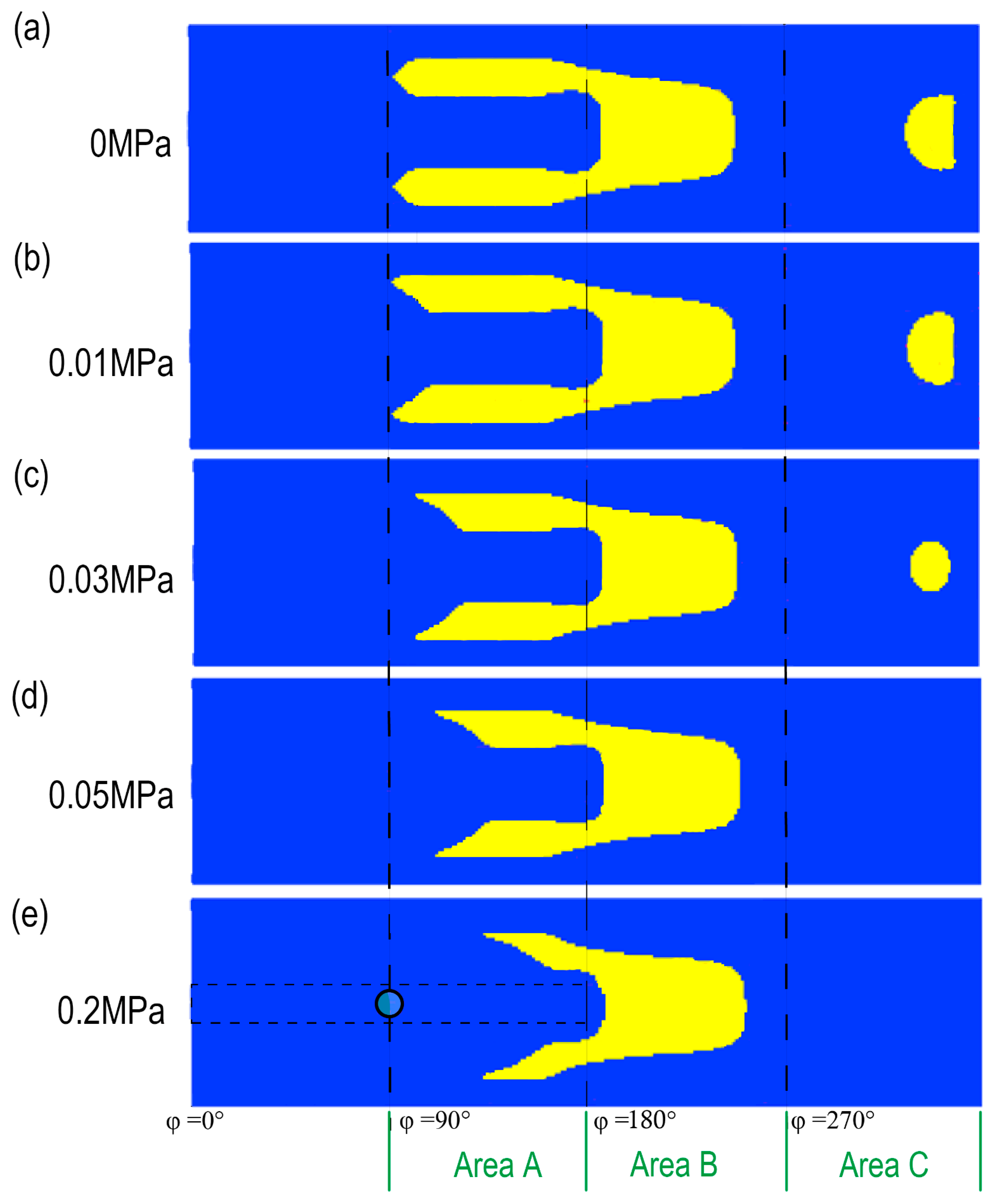
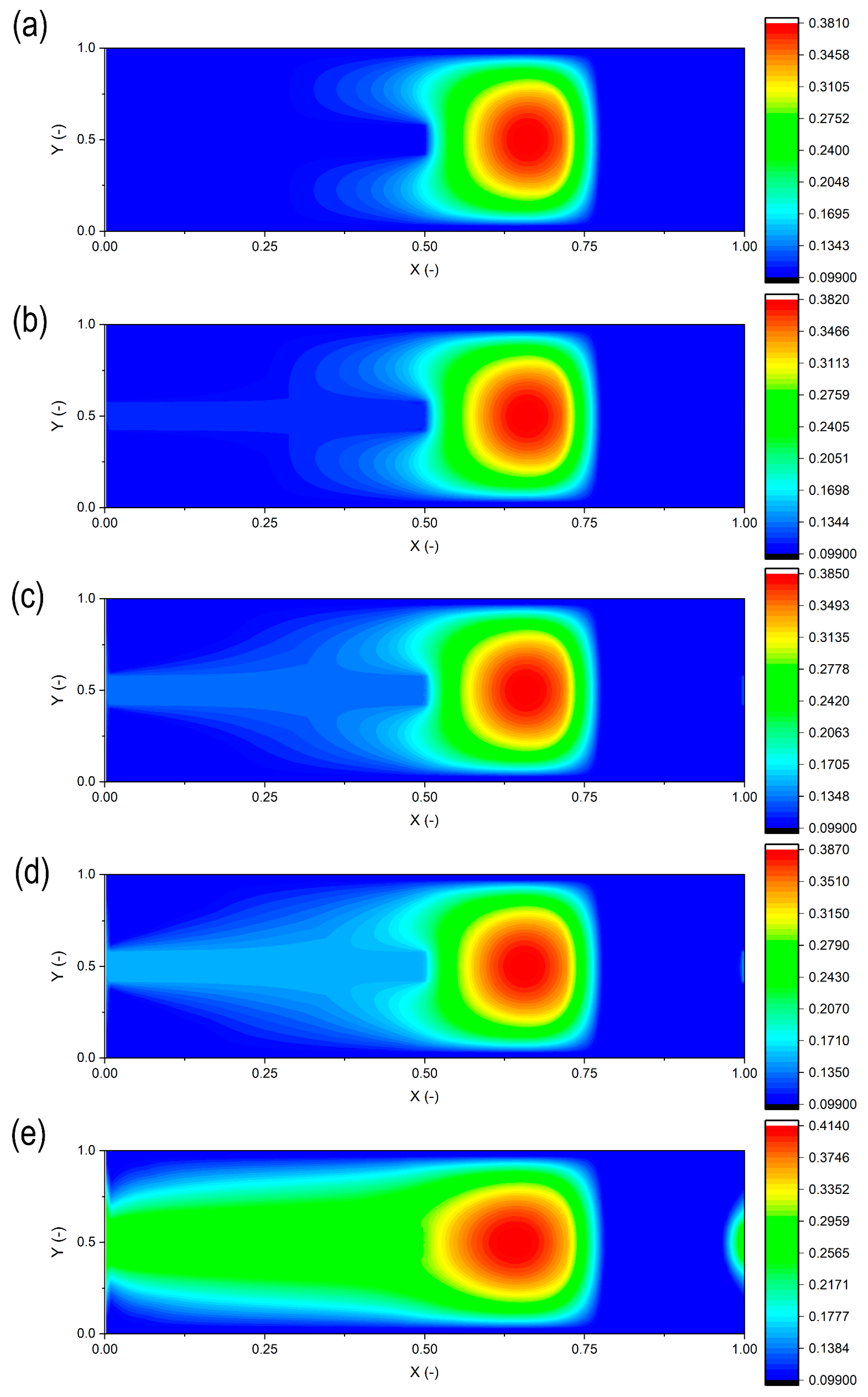
The optimization results of the bearing bush are distributed in a plane coordinate system, as shown in Figure 4. Figure 5 shows the comparison of the total pressure distribution results under different inlet oil pressures. The total pressure includes both the hydrodynamic pressure and the asperity contact pressure. Its distribution is influenced by the textured bush and increases with a higher inlet oil pressure. The coordinate X is dimensionless, defined as x / L , while Y is also dimensionless and given by y / B . Additionally, X corresponds to the angular coordinate φ: φ = 0 ° corresponds to X = 0 , and φ = 360 ° corresponds to X = 1 . When the inlet oil pressure is 0, the optimized texture appears as a “cavity bullet” shape in the range of φ = 0 ° to φ = 270 ° . After exiting the extrusion zone, a semicircular texture exists in the range of φ = 270 ° to φ = 360 ° . Due to the oil groove, a “texture vacuum zone” forms around it. The “texture vacuum zone” refers to the region covered by the circumferential oil groove where no texture optimization was applied. This design ensures uninterrupted oil flow from the circumferential oil groove, maintaining effective lubrication supply. The absence of textures in this zone directly influences the optimization results by constraining the texture design to adjacent areas (A, B, and C), thereby affecting pressure distribution. Along with the increase in the inlet oil pressure, the overall length of the texture shortens. By dividing the texture into three areas (A, B, and C) for observation, the following trends are found: (1) In Area A, the texture continues to shorten to the right. The curvature change inside the texture gradually decreases, and the “bullet” tail becomes sharp. (2) In Area B, the texture contour remains nearly unchanged. The line near the oil groove gradually curves inward, transforming from a vertical line at P i n = 0   M P a to a curved arc at P i n = 0.2   M P a . (3) In Area C, the semicircular texture shrinks with the increasing inlet oil pressure and disappears at P i n = 0.05   M P a .
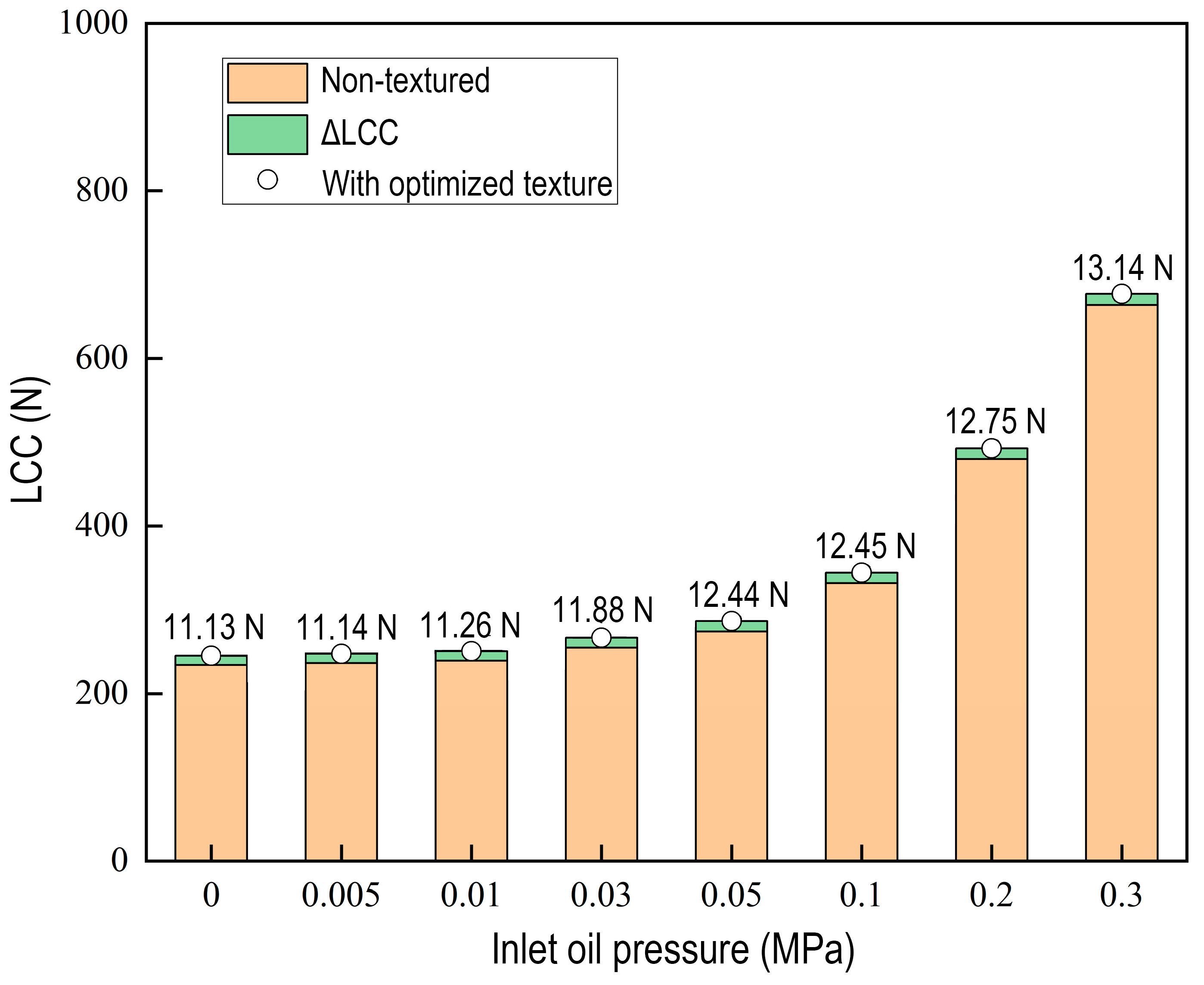
After uniformly assigning the depth h w to the optimized textures, these results are compared with those of an untextured journal bearing. As shown in Figure 6, the LCCs for the textured and untextured journal bearings increase continuously with the rise in the inlet oil pressure. In particular, the textured journal bearing has a higher LCC. It appears that the optimized textures enhance the LCC. With the increasing inlet oil pressure, the enhancement effect improves slightly, growing from an improvement of 11.13 N at P i n = 0   M P a to 13.14 N at P i n = 0.3   M P a , though the rate of improvement diminishes at higher pressures.

4.2. The Influence of Eccentricity Ratio

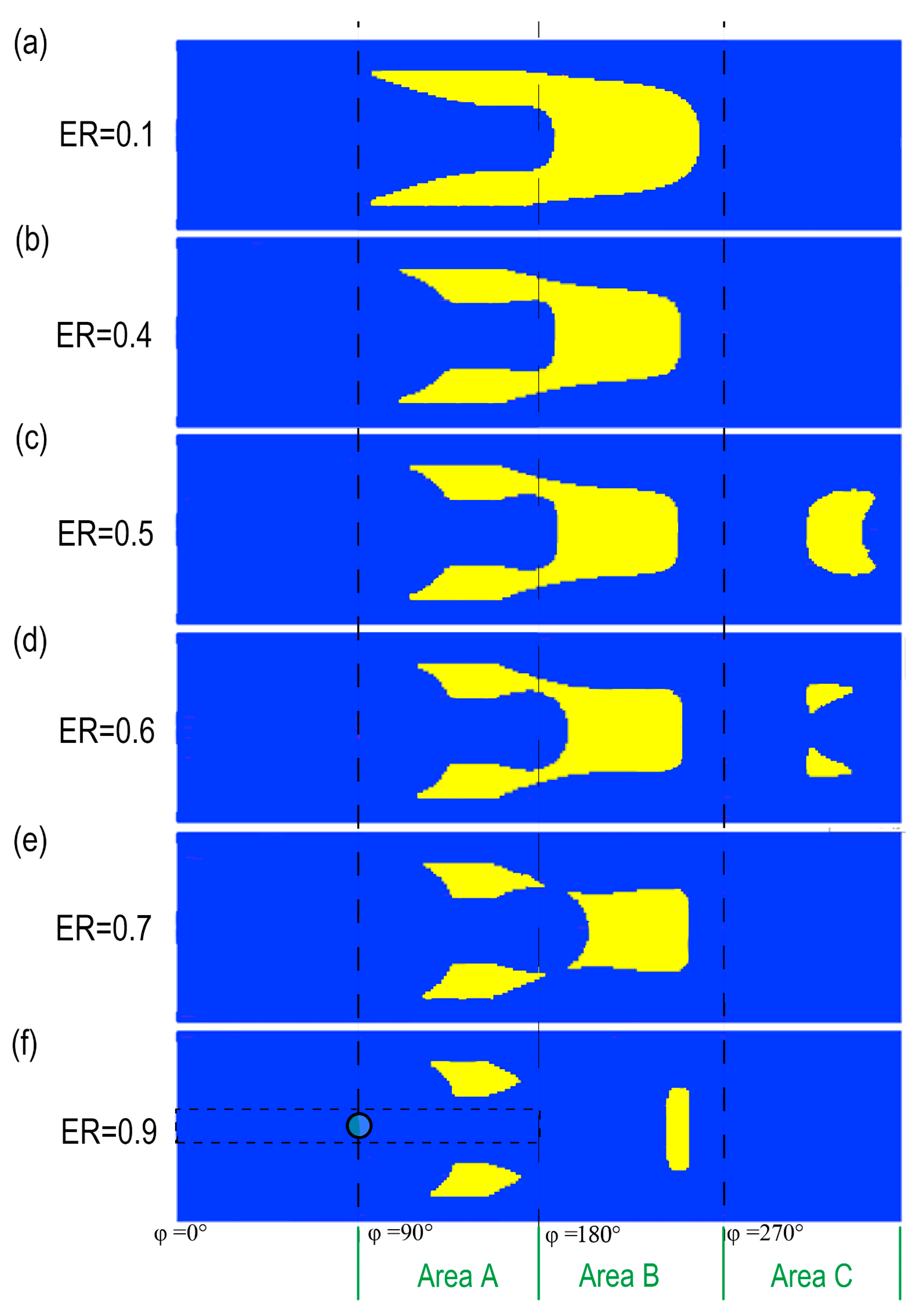
In this section, in order to find the influence of the eccentricity ratio, the eccentricity ratio is changed, and the inlet oil pressure is set at 0.05 MPa. Figure 7 shows the optimization results under different eccentricity ratios. Comparisons of the total pressure optimization results under different eccentricity ratios are shown in Figure 8. According to the results, there are also three areas: Area A, Area B, and Area C. For Area A: the texture length gradually shortens. The inner lines of the forked tail transition from an “oblique line + horizontal line” combination to a “concave curve + horizontal line” configuration. For Area B: at E R = 0.1 , the texture head contour is fully circular. Along with the increase in the eccentricity ratio, the overall texture shrinks, with its top position retracting backward. While the position stabilizes at E R = 0.5 , the texture near the oil groove continues to shrink (“necking”). At E R = 0.7 , the texture in Area B disconnects from Area A and splits into three separate texture segments. For Area C: textures here also evolve. The single “crescent” texture at E R = 0.5 shrinks and splits into two small “triangle” textures at E R = 0.6 , then disappears entirely at E R = 0.7 .
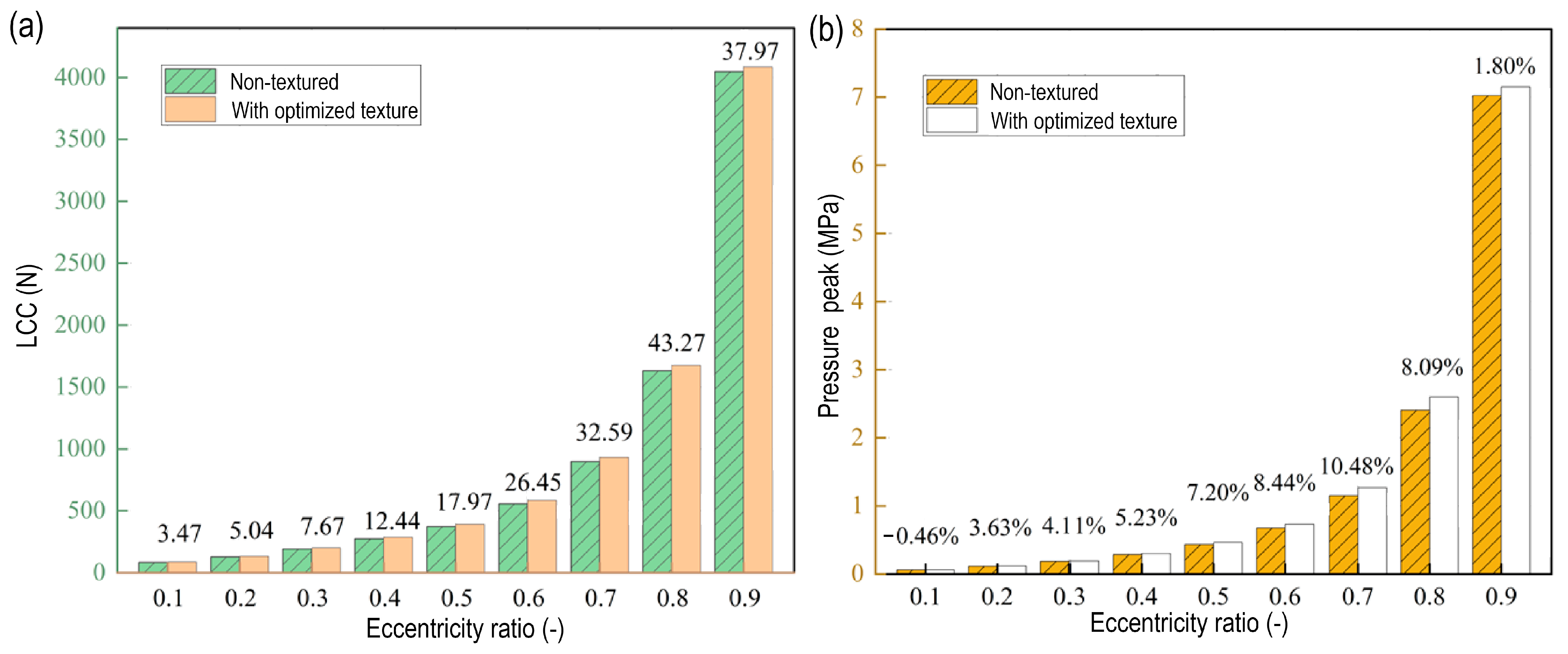
Figure 9a shows the results of the LCC when the textures are optimized with uniform depth. Along with the increase in the eccentricity ratio, the enhancement effect of the optimized textures generally follows a trend of first increasing and then decreasing. This behavior is justified by the changing hydrodynamic conditions. At low eccentricity ratios (e.g., ER = 0.1), the oil film thickness is relatively large, resulting in lower hydrodynamic pressures where textures provide minimal improvement due to reduced interaction with the flow. As the eccentricity ratio increases (e.g., ER = 0.1 to ER = 0.8), the decreasing film thickness enhances the effectiveness of textures in generating additional hydrodynamic pressure through mechanisms like micro-cavitation and optimized flow redistribution, leading to a significant rise in the LCC. However, at extremely high eccentricity ratios (e.g., ER = 0.9), while the bearing remains in the hydrodynamic regime, the small film thickness may reduce texture functionality. The textures become less effective, resulting in a decline in enhancement. The improvement value of the LCC rises from 3.47 N at E R = 0.1 to 43.27 N at E R = 0.8 , before declining to 37.97 N at E R = 0.9 . Figure 9b shows the variation in the pressure peak for the untextured and textured bearings. At E R = 0.1 , the pressure peak of the untextured bearing is slightly higher than that of the textured bearing, with a difference of approximately 0.46%. Thereafter, the textured bearing exhibits higher pressure peaks. The pressure peak difference initially increases and then decreases with the eccentricity ratio, peaking at approximately 10.48% when ER = 0.7. This trend coincides with the LCC, indicating that surface textures are most effective at intermediate eccentricity ratios. Under these conditions, the hydrodynamic effects are optimized without being limited by extreme oil film thinning.

4.3. The Influence of Misalignment

Misalignment is a critical issue affecting the performance of journal bearings. It can cause problems such as increased bearing pressure and rapid temperature rise, easily pushing bearings into harsh lubrication conditions and accelerating wear. In this section, the journal bearing with a high-eccentricity ratio was studied to analyze the trend of optimized textures under different degrees of misalignment. The eccentricity ratio is set to 0.8, as this value corresponds to the condition where the LCC improvement from texture optimization is maximized, based on prior results (e.g., Figure 9a), ensuring that the analysis focuses on a regime of high texture effectiveness. The inlet oil pressure remains at 0.05 MPa, which was chosen as a representative value from the optimization study under varying inlet oil pressures, allowing consistent comparison of misalignment effects without confounding inlet oil pressure variations. Misalignment only considers deflection in the Y c Z c plane, with the misalignment angle denoted as θ y , ranging from 0° to 0.14°.
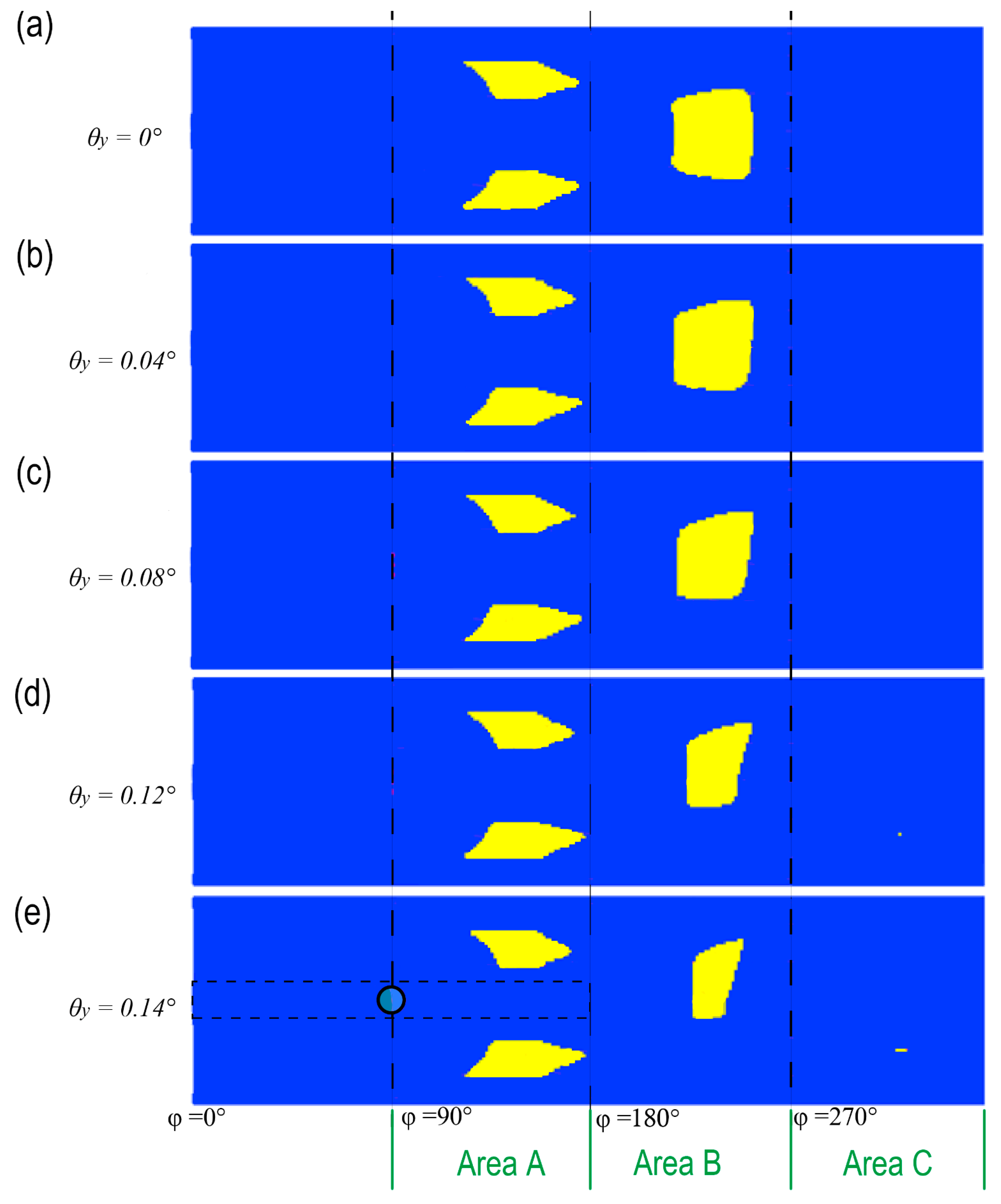
Figure 10 shows the optimization results with different degrees of misalignment. As shown in Figure 10, along with the increase in the misalignment degree, in the range from φ = 0 ° to φ = 270 ° , the texture changes from symmetric distribution to asymmetric distribution. In Area A, the two upper and lower textures show different change trends. The texture at the upper end shows a shortening trend, while the texture at the lower end shows a lengthening trend. For the texture in Area B, the entire area shows a decreasing trend with the increase in the misalignment degree. The reduction rates of the upper and lower sides of the texture are different, and the lower side of the texture decreases faster. When the misalignment degree reaches 0.12°, a tiny texture appears in Area C. When the misalignment angle increases to 0.14°, the texture increases accordingly.
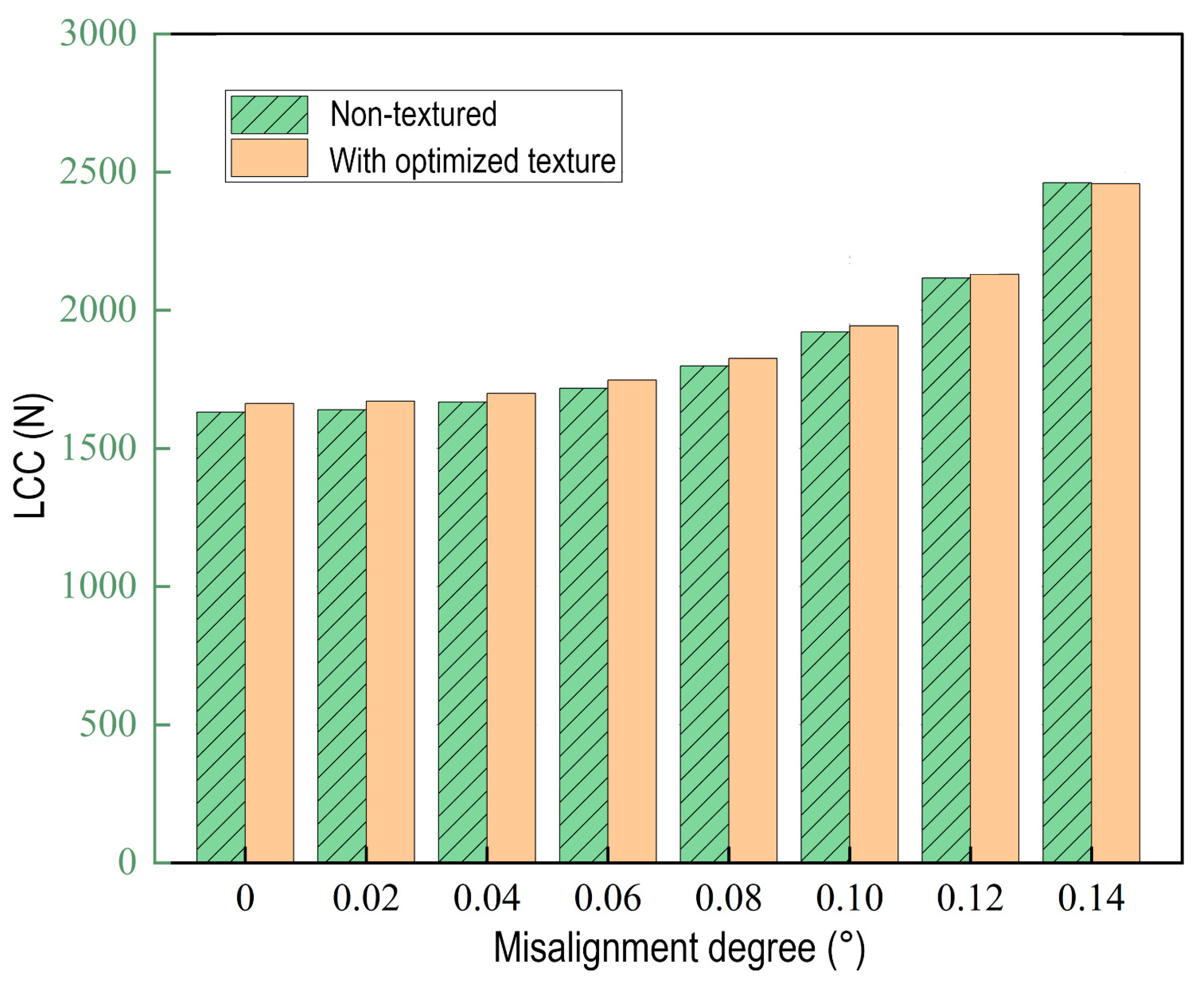
The results of the textured bearing are also compared with the results of the untextured bearing. Figure 11 shows the LCC results for the untextured and textured bearing. Along with the increases in the misalignment degree, the LCC of the textured and untextured bearing continues to increase, and the magnitude of the increase is also growing. Although the LCC of the textured bearing under different degrees of misalignment has consistently exceeded that of the non-textured bearing, the magnitude of LCC improvement conferred by the texture gradually diminishes as the misalignment degree increases. A probable explanation is that the issues induced by misalignment, such as severe pressure concentrations and critically thin films, diminish the beneficial effects of the surface textures.

4.4. The Influence of Rotation Direction

For many mechanical devices, they have two rotation modes. One is the forward rotation mode; another is the reverse rotation mode. When introducing textures on the surface of bearings, appropriate texture shapes are conducive to enhancing the hydrodynamic effect. Although the textures optimized under the forward rotation mode can improve the bearing performance in the corresponding mode, it is necessary to study whether their effectiveness is maintained when applied to the reverse rotation mode. Aiming at the two operating states of forward and reverse rotations, it is expected to optimize the surface textures through a multi-objective optimization method. Considering the existence of two rotation directions, in order to balance the optimization benefits generated by the obtained textures, the weights for bidirectional optimization are each taken as 0.5, that is, f   =   0.5 f 1   +   0.5 f 2 . f 1 is the LCC obtained under the forward rotation mode, while f 2 is the LCC obtained under the reverse rotation mode.
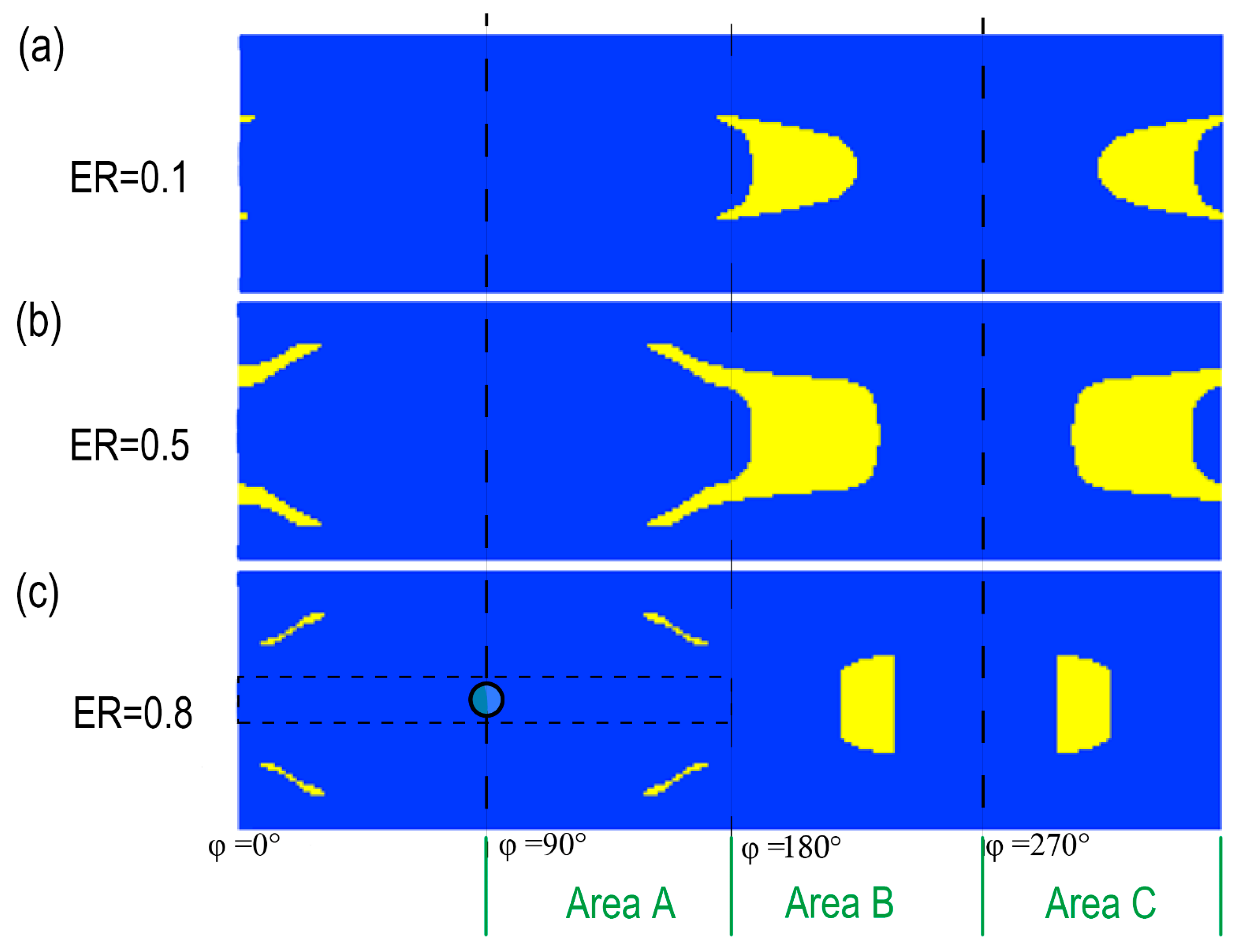
The operating conditions remain at p i n = 0.05   M P a and a rotational speed of 1800 rpm. Without considering the misalignment issue, simulations are performed for bearings with a low eccentricity ratio ( E R = 0.1 ), medium eccentricity ratio ( E R = 0.5 ), and high eccentricity ratio ( E R = 0.8 ), respectively. The textures obtained by bidirectional optimization are shown in Figure 12. The optimized textures exhibit symmetric distribution with respect to the oil groove in the central region. This symmetry is a direct consequence of the bidirectional optimization with equal weights (0.5 for each rotation direction), which aims to balance the hydrodynamic performance in both forward and reverse rotations. Specifically, the symmetric design ensures that textures generate comparable pressure distributions and oil flow patterns around the oil groove regardless of the rotation direction. This avoids the bias that would occur with unidirectional optimization, where textures might be tailored exclusively to one direction, potentially harming reverse rotation performance. The symmetry promotes uniform LCC enhancement by maintaining consistent micro-cavitation and flow redistribution effects symmetrically, which is crucial for applications involving bidirectional operation. Notably, the mid-section of the inlet oil groove forms a “vacuum zone” under the influence of the inlet oil pressure. The circumferential texture distributions of low- and medium-eccentricity ratio bearings are less affected, while the “vacuum zone” at both ends of the oil groove in the high-eccentricity ratio bearing expands significantly. As the eccentricity ratio increases, the texture configuration near the sector around φ = 270° undergoes noticeable changes.
Table 3 shows the comparison results. In Table 3, the LCC improvement effects of unidirectionally optimized textured bearings under forward and reverse rotations were compared with those of bidirectionally optimized textured bearings. As shown in Table 3, an interesting observation occurs at ER = 0.8 under reverse rotation, where a value of –19.53 N is recorded. This suggests that textures optimized specifically for forward rotation may be ineffective or even detrimental under reverse rotation. These results highlight the importance of the rotation direction in texture optimization and its significant influence on LCC enhancement. Textures optimized for forward rotation improve the bearing performance in that specific mode but do not necessarily benefit—and may even impair—performance under reverse rotation. The optimum design of the textured surface depends on the operating conditions [3]. Specifically, the higher the eccentricity ratio, the more pronounced the detrimental impact of the texture. In contrast, the bidirectionally optimized texture, owing to its symmetric configuration, can enhance the LCC in both forward and reverse rotations. Although its LCC improvement effect is less targeted than that of the unidirectional counterpart, the enhancement remains considerable.

5. Conclusions

This study developed a mixed lubrication model and applied the adjoint optimization method to texture design for journal bearings with circumferential oil grooves. The key findings are summarized as follows:
1. Optimal texture geometry is sensitive to operating and geometric parameters. Increasing the oil supply pressure shortens textures and initiates friction reduction at 0.05 MPa, though this effect diminishes with higher pressure (e.g., LCC improvement plateaus at 13.14 N at P i n   = 0.3 MPa). A rising eccentricity ratio induces progressive necking in the dominant texture structure, culminating in fracture at ER = 0.7. The LCC enhancement from textures peaks at moderate eccentricities (e.g., 43.27 N at ER = 0.8) before declining to 37.97 N at ER = 0.9 due to reduced hydrodynamic effectiveness. While increasing the misalignment angle boosts the absolute LCC, it concurrently reduces the relative performance gain from textures.
2. Multi-objective optimization enabled the creation of bidirectionally optimized textures. Comparative analysis under forward and reverse rotation revealed that while unidirectionally optimized textures achieve higher peak performance in their designated rotation direction (e.g., 43.27 N at E R = 0.8 ), bidirectionally optimized textures offer significantly enhanced robustness, maintaining effective performance under reverse rotation conditions (e.g., 12.00 N at E R = 0.8 ) where unidirectional textures perform poorly (−19.53 N).
This study fundamentally advances the theoretical framework for journal bearing design by rigorously quantifying the synergistic effects of critical factors like oil grooves and misalignment. The demonstrated efficacy of the adjoint method and the insights into parameter-driven texture evolution are directly applicable to future bearing engineering.
Future work could focus on several directions: (1) Experimental validation of the optimized textures under real-world operating conditions to verify numerical predictions; (2) extension of the optimization framework to include thermal effects and transient dynamics for more comprehensive performance analysis; (3) investigation of texture scalability and manufacturability for industrial applications; (4) integration of machine learning techniques to accelerate the optimization process and handle multi-parameter dependencies; and (5) application of the methodology to other bearing types, such as thrust bearings or rolling element bearings, to explore broader tribological implications.

Author Contributions

D.Z. performed the main tasks of modeling, simulation implementation, data analysis, visualization, and drafting the initial manuscript. H.W. conceived the research ideas, coordinated and supervised the development of the work, provided theoretical guidance, and critically reviewed and edited the manuscript. C.G. contributed to the modeling strategy and data interpretation, secured funding for the project, and revised the manuscript. All authors have read and agreed to the published version of the manuscript.

Funding

This study is sponsored by the National Natural Science Foundation of China (No. 52305207).

Data Availability Statement

The data used to support the findings of this study are available from the corresponding author upon request.

Conflicts of Interest

The authors declare no conflicts of interest.

Nomenclature

The following nomenclatures are used in this manuscript:
β Asperity radius (m)
C l Bearing radial clearance (m)
χ p The adjoint pressure (-)
χ δ The adjoint cavitation factor (-)
δ The cavity fraction (-)
E 1 The elastic modulus of shaft (MPa)
E 2 The elastic modulus of bearing (MPa)
η The asperity density (1/m2)
F X c The X c component of the LCC (N)
F Y c The Y c component of the LCC (N)
G d Groove depth (m)
G w Groove width (m)
h Oil film thickness (m)
h g The film thickness change caused by the oil groove (m)
h p r o f The oil film thickness without taking the texture into consideration (m)
h t The optimized texture distribution (m)
λ λ = h / σ , the film thickness ratios (-)
LCC Load-carrying capacity (N)
MMV Moving morphable void (-)
μ Lubricant viscosity (Pa·s)
υ 1 Poisson ratio of shaft (-)
υ 2 Poisson ratio of bearing (-)
Ω Oil inlet hole area (m2)
Ω 0 The computational domain (m2)
p Hydrodynamic pressure (Pa)
p a s p Asperity contact pressure (Pa)
ϕ c The contact factor (-)
ϕ s Shear flow factor (-)
ϕ x , ϕ y Pressure flow factors (-)
ρ Density of lubricant (kg/m3)
σ Equivalent surface roughness (m)
SQP Sequential Quadratic Programming (-)
θ x , θ y The misalignment parameter ( ° )
U Shaft velocity (m/s)
X c , Y c The position of the shaft (-)
X c m , Y c m The position of the shaft center (-)

References

  1. Chaudhary, S.; Verma, R. A Comprehensive Review of Journal Bearing Models: Comparative Analysis of Thermal, Elastic, and Hydrodynamic Approaches Considering Misalignment, Surface Texture, Turbulence, and Cavitation. J. Tribol. 2025, 147, 110802. [Google Scholar] [CrossRef]
  2. Jeon, W.-J.; Hong, S.-H. A New Type of Misaligned Journal Bearing with Flexible Structure. Lubricants 2023, 11, 256. [Google Scholar] [CrossRef]
  3. Cupillard, S.; Glavatskih, S.; Cervantes, M.J. Computational fluid dynamics analysis of a journal bearing with surface texturing. Proc. Inst. Mech. Eng. Part J J. Eng. Tribol. 2008, 222, 97–107. [Google Scholar] [CrossRef]
  4. Yu, R.; Chen, W.; Li, P. The analysis of elastohydrodynamic lubrication in the textured journal bearing. Proc. Inst. Mech. Eng. Part J J. Eng. Tribol. 2016, 230, 1197–1208. [Google Scholar] [CrossRef]
  5. Wang, L.; Han, Z.; Chen, G.; Su, H. Thermo-hydrodynamic analysis of large-eccentricity hydrodynamic bearings with texture on journal surface. Proc. Inst. Mech. Eng. Part C J. Mech. Eng. Sci. 2017, 232, 3564–3569. [Google Scholar] [CrossRef]
  6. Morris, N.J.; Shahmohamadi, H.; Rahmani, R.; Rahnejat, H.; Garner, C.P. Combined experimental and multiphase computational fluid dynamics analysis of surface textured journal bearings in mixed regime of lubrication. Lubr. Sci. 2018, 30, 161–173. [Google Scholar] [CrossRef]
  7. Gu, C.; Meng, X.; Wang, S.; Ding, X. Modeling a Hydrodynamic Bearing With Provision for Misalignments and Textures. J. Tribol. 2020, 142, 41801–41812. [Google Scholar] [CrossRef]
  8. Jin, J.; Chen, X.; Fu, Y.; Chang, Y. Optimal design of the slip–texture on a journal-bearing surface. Ind. Lubr. Tribol. 2020, 73, 230–237. [Google Scholar] [CrossRef]
  9. Pradhan, S.K.; Kumar, R.; Mishra, P.C. Material modeling and optimization of rough elliptic bore journal bearing. Mater. Today Proc. 2021, 44, 1021–1027. [Google Scholar] [CrossRef]
  10. Gu, C.; Cui, Y.; Zhang, D. Research on the Optimal Design Approach of the Surface Texture for Journal Bearings. Lubricants 2024, 12, 111. [Google Scholar] [CrossRef]
  11. Khatri, C.B.; Yadav, S.K.; Thakre, G.D.; Rajput, A.K. Design optimization of vein-bionic textured hydrodynamic journal bearing using genetic algorithm. Acta Mech. 2023, 235, 167–190. [Google Scholar] [CrossRef]
  12. Codrignani, A.; Savio, D.; Pastewka, L.; Frohnapfel, B.; van Ostayen, R. Optimization of surface textures in hydrodynamic lubrication through the adjoint method. Tribol. Int. 2020, 148, 106352. [Google Scholar] [CrossRef]
  13. Ramos, D.J.; Daniel, G.B. Microgroove optimization to improve hydrodynamic bearing performance. Tribol. Int. 2022, 174, 107667. [Google Scholar] [CrossRef]
  14. Pattnayak, M.R.; Pandey, R.K.; Dutt, J.k. Performance improvement of an oil-lubricated journal bearing using bionic-textures fused micro-pockets. J. Tribol. 2021, 144, 41804. [Google Scholar] [CrossRef]
  15. Zhang, W.; Tian, H.; Zhu, B.; Guo, X.; Youn, S.K. Multi-Set MMV Topology Optimization Approach for Sliding Surface Texture Design. Int. J. Numer. Methods Eng. 2024, 126, e7612. [Google Scholar] [CrossRef]
  16. Tucker, P.G.; Keogh, P.S. A Generalized Computational Fluid Dynamics Approach for Journal Bearing Performance Prediction. Proc. Inst. Mech. Eng. Part J J. Eng. Tribol. 1995, 209, 99–108. [Google Scholar] [CrossRef]
  17. Lijesh, K.P.; Muzakkir, S.M.; Hirani, H.; Thakre, G.D. Control on wear of journal bearing operating in mixed lubrication regime using grooving arrangements. Ind. Lubr. Tribol. 2016, 68, 458–465. [Google Scholar] [CrossRef]
  18. Nichols, B.R.; Fittro, R.L.; Goyne, C.P. Steady-State Tilting-Pad Bearing Performance Under Reduced Oil Supply Flow Rates. J. Tribol. 2018, 140, 51701. [Google Scholar] [CrossRef]
  19. Brito, F.P.; Miranda, A.S.; Claro, J.C.P.; Teixeira, J.C.; Costa, L.; Fillon, M. Thermohydrodynamic modelling of journal bearings under varying load angle and negative groove flow rate. Proc. Inst. Mech. Eng. Part J J. Eng. Tribol. 2014, 228, 955–973. [Google Scholar] [CrossRef]
  20. Profito, F.J.; Vladescu, S.C.; Reddyhoff, T.; Dini, D. Numerical and experimental investigation of textured journal bearings for friction reduction. Tribol. Int. 2024, 195, 109643. [Google Scholar] [CrossRef]
  21. Mehrjardi, M.Z.; Shooroki, A.R.; Rabani, M.; Rabani, M. Effect of Surface Texture Depth with Various Geometric Shapes on the Steady-State Performance and Dynamic Stability of Noncircular Lobed Journal Bearings. Appl. Sci. 2025, 15, 4412. [Google Scholar] [CrossRef]
  22. Kong, H.; Gu, C.; Zhang, D.; Wu, L. Topology Optimization of Textured Journal Bearings. Lubricants 2025, 13, 251. [Google Scholar] [CrossRef]
  23. Li, Y.; Ning, Y.; Zhang, D.; Zhi, Y. A Model of Hydrodynamic Bearings With Circumferential Parallel Arranged Grooves. J. Tribol. 2023, 145, 104102. [Google Scholar] [CrossRef]
  24. Zhang, X.; Zhao, S.; Wang, K. Influence of Structural Parameters of Water-Lubricated Bearings on Vibration Characteristics of Marine Magnetic Pumps. Water 2023, 15, 4060. [Google Scholar] [CrossRef]
  25. Zhu, J.; Li, H.; Fu, J.; Liu, X. Hydrodynamic Lubrication Performance Analysis of the Self-Cooled Bearing Structure in Aero-Gear Pump Considering the Cavitation Effect. In Proceedings of the 2018 9th International Conference on Mechanical and Aerospace Engineering (ICMAE), Budapest, Hungary, 10–13 July 2018; pp. 472–477. [Google Scholar]
  26. Zhang, X.; Liu, C.; Zhao, B. An optimization research on groove textures of a journal bearing using particle swarm optimization algorithm. Mech. Ind. 2021, 22, 1. [Google Scholar] [CrossRef]
  27. Han, Y.; Fu, Y. Influence of micro-grooves on the lubrication performance of a misaligned bearing. Proc. Inst. Mech. Eng. Part J J. Eng. Tribol. 2019, 234, 887–899. [Google Scholar] [CrossRef]
  28. Xie, Z.; Shen, N.; Zhu, W.; Tian, W.; Hao, L. Theoretical and experimental investigation on the influences of misalignment on the lubrication performances and lubrication regimes transition of water lubricated bearing. Mech. Syst. Signal Process. 2021, 149, 107211. [Google Scholar] [CrossRef]
  29. Sahu, K.; Sharma, S.C.; Ram, N. Misalignment and Surface Irregularities Effect in MR Fluid Journal Bearing. Int. J. Mech. Sci. 2022, 221, 107196. [Google Scholar] [CrossRef]
  30. Pradhan, S.K.; Kumar, R.; Mishra, P.C. Grey-Fuzzy Hybrid Optimization for Thermohydrodynamic Performance Prediction of Misaligned Rough Elliptic Bore Journal Bearing. Lubricants 2022, 10, 274. [Google Scholar] [CrossRef]
  31. Zhou, Z.; Zhou, X.; Gryllias, K.; Zhu, H.; Liu, X. Optimization of Stern Bearing Lubrication Performance Under Misaligned Journal Conditions Based on Length-to-Diameter Ratio. J. Tribol. 2026, 148, 14102. [Google Scholar] [CrossRef]
  32. Sun, X.; Chocholaty, B.; Liu, Y.; Marburg, S. Nonlinear dynamic behavior of a rotor-bearing system considering time-varying misalignment. Int. J. Mech. Sci. 2024, 284, 109772. [Google Scholar] [CrossRef]
  33. Chen, Y.; Zhang, H.; Li, X.; Shi, Z.; Gu, F. Tribo-dynamic performance analysis of engine main bearings with provision for wear progression and dynamic misalignment. Eng. Fail. Anal. 2025, 169, 109196. [Google Scholar] [CrossRef]
  34. Patir, N.; Cheng, H.S. Application of Average Flow Model to Lubrication Between Rough Sliding Surfaces. J. Lubr. Technol. 1979, 101, 220–229. [Google Scholar] [CrossRef]
  35. Patir, N.; Cheng, H.S. An Average Flow Model for Determining Effects of Three-Dimensional Roughness on Partial Hydrodynamic Lubrication. J. Lubr. Technol. 1978, 100, 12–17. [Google Scholar] [CrossRef]
  36. Greenwood, J.; Williamson, J. Contact of nominally flat surfaces. Proc. R. Soc. Lond. Ser. A Math. Phys. Sci. 1966, 295, 300–319. [Google Scholar] [CrossRef]
  37. Ausas, R.F.; Jai, M.; Buscaglia, G.C. A Mass-Conserving Algorithm for Dynamical Lubrication Problems With Cavitation. J. Tribol. 2009, 131, 31702. [Google Scholar] [CrossRef]
  38. Tala-Ighil, N.; Maspeyrot, P.; Fillon, M.; Bounif, A. Effects of surface texture on journal-bearing characteristics under steady-state operating conditions. Proc. Inst. Mech. Eng. Part J J. Eng. Tribol. 2007, 221, 623–633. [Google Scholar] [CrossRef]
  39. Rohde, S.M.; McAllister, G.T. On the optimization of fluid film bearings. Proc. R. Soc. Lond. A Math. Phys. Sci. 1997, 351, 481–497. [Google Scholar] [CrossRef]
  40. Shen, C.; Khonsari, M.M. Numerical optimization of texture shape for parallel surfaces under unidirectional and bidirectional sliding. Tribol. Int. 2015, 82, 1–11. [Google Scholar] [CrossRef]
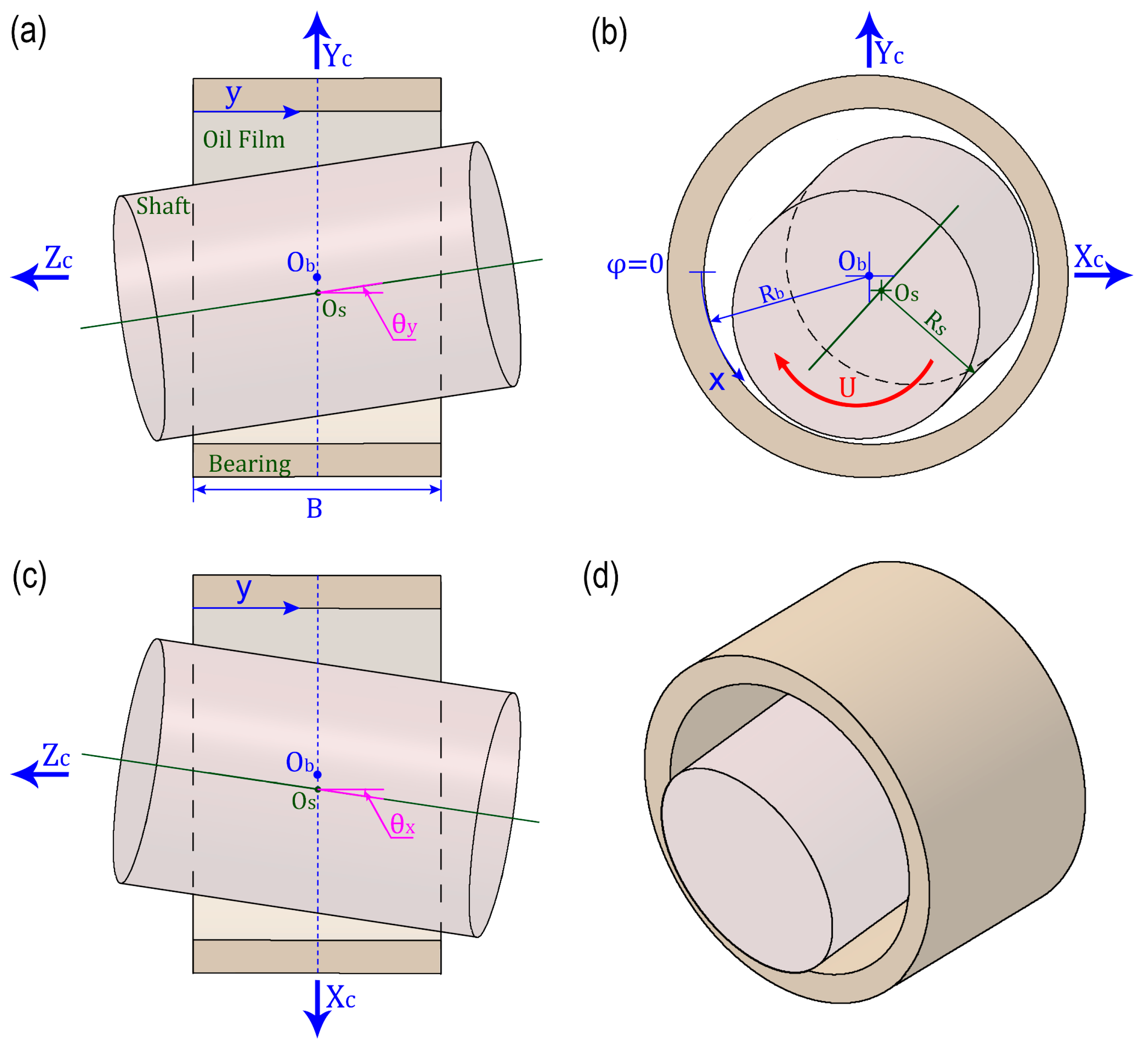
Figure 1. Schematic diagram of journal bearing in misalignment state: (a) main view, (b) left view, (c) top view, and (d) axonometric drawing.
Lubricants 13 00479 g001
Figure 2. The overview of unfolding the bearing bush.
Lubricants 13 00479 g002
Figure 3. (a) The schematic of a square slider bearing; (b) the optimal result reported by Rohde and McAllister [39]; (c) the optimal result from Shen and Khonsari [40]; (d) the optimal result using optimization through the adjoint method.
Lubricants 13 00479 g003
Figure 4. Comparison of texture optimization results under different inlet oil pressures: (a) P i n = 0   M P a , (b) P i n = 0.01   M P a , (c) P i n = 0.03   M P a , (d) P i n = 0.05   M P a , (e) P i n = 0.2   M P a .
Lubricants 13 00479 g004
Figure 5. Comparison of the total pressure distribution results under different inlet oil pressures: (a) P i n = 0   M P a , (b) P i n = 0.01   M P a , (c) P i n = 0.03   M P a , (d) P i n = 0.05   M P a , (e) P i n = 0.2   M P a .
Lubricants 13 00479 g005
Figure 6. Variations in LCC of optimized texture bearings and untextured bearings under different inlet oil pressures.
Lubricants 13 00479 g006
Figure 7. Comparison of texture optimization results under different eccentricity ratios: (a) E R = 0.1 , (b) E R = 0.4 , (c) E R = 0.5 , (d) E R = 0.6 , (e) E R = 0.7 , (f) E R = 0.9 .
Lubricants 13 00479 g007
Figure 8. Comparison of the total pressure distribution results under different eccentricity ratios: (a) E R = 0.1 , (b) E R = 0.4 , (c) E R = 0.5 , (d) E R = 0.6 , (e) E R = 0.7 , (f) E R = 0.9 .
Lubricants 13 00479 g008
Figure 9. Comparison results of the optimized textured bearing and the untextured bearing under different eccentricity ratios: (a) Variations in LCC, (b) variations in pressure peak.
Lubricants 13 00479 g009
Figure 10. Comparison of texture optimization results under different degrees of misalignment: (a) θ y = 0 ° , (b) θ y = 0.04 ° , (c) θ y = 0.08 ° , (d) θ y = 0.12 ° , (e) θ y = 0.14 ° .
Lubricants 13 00479 g010
Figure 11. Variations in LCC for the optimized textured bearings and non-textured bearings under different degrees of misalignment.
Lubricants 13 00479 g011
Figure 12. The results obtained by bidirectional optimization under different eccentricity ratios: (a) ER = 0.1, (b) ER = 0.5, (c) ER = 0.8.
Lubricants 13 00479 g012
Table 1. The comparison results about the performance parameters of the smooth journal bearing system.
ParametersResults from Tala-Ighil et al. [38]Present Work
Applied load (N)12,60012,600
Eccentricity ratio0.6010.601
Maximum pressure (MPa)7.707.72
Friction   torque   ( N · m )1.2171.220
Attitude angle (degree)50.550.7
Table 2. The simulation conditions.
ParameterValueUnit
Bearing diameter50 m m
Bearing   radial   clearance ,   C l 0.25 m m
Bearing   width ,   B 38 m m
Groove   width ,   G w 6 m m
Groove   depth ,   G d 1.5 m m
Groove   radius ,   R G 2.5 m m
Journal mass3.2 k g
Texture   depth ,   h w 10 μ m
Elastic   modulus   of   bearing   E 2   ( shaft ,   E 1 )66 (210) G P a
Poisson   ratio   of   bearing   υ 2   ( shaft ,   υ 1 )0.33 (0.269)-
Lubricant   viscosity ,   μ 0.124 P a · s
Lubricant   density ,   ρ 844.560 k g / m 3
Equivalent   surface   roughness ,   σ 0.55383 μ m
σ / β 0.064589-
η β σ 0.045045-
Table 3. The variations in LCC with eccentricity ratio for the results of unidirectional and bidirectional optimized textures.
Eccentricity RatioUnidirectional Optimized ResultsBidirectional Optimized Results
Forward   Rotation   L C C / N Reverse   Rotation   L C C / N L C C / N
0.13.473.854.84
0.517.971.9812.01
0.843.27−19.5312.00
Disclaimer/Publisher’s Note: The statements, opinions and data contained in all publications are solely those of the individual author(s) and contributor(s) and not of MDPI and/or the editor(s). MDPI and/or the editor(s) disclaim responsibility for any injury to people or property resulting from any ideas, methods, instructions or products referred to in the content.