Article

Study on Thermal Characteristics of Angular Contact Ball Bearings Considering Roundness Error

1
School of Mechatronics Engineering, Henan University of Science and Technology, Luoyang 471003, China
2
Longmen Laboratory, Luoyang 471000, China
3
Henan Key Laboratory for Machinery Design and Transmission System, Henan University of Science and Technology, Luoyang 471003, China
*
Author to whom correspondence should be addressed.
Lubricants 2024, 12(2), 43; https://doi.org/10.3390/lubricants12020043
Submission received: 23 November 2023 / Revised: 25 January 2024 / Accepted: 28 January 2024 / Published: 3 February 2024
(This article belongs to the Special Issue Advances in Bearing Lubrication and Thermodynamics 2023)

Abstract

:
To develop an angular contact ball bearing with low power consumption, a heat generation calculation model for angular contact ball bearings has been established based on bearing quasi dynamics, elastohydrodynamic lubrication theory, heat transfer theory, and Kirchhoff’s law of energy conservation, considering the effects of roundness error, bearing preload, centrifugal effect, and thermal expansion. The correctness of the model is verified through experiments. The influence of different operating conditions and roundness errors on the thermal characteristics of angular contact ball bearings is analyzed. The results of the calculation indicate that when the roundness error order is equal to the number of balls n/2 ± 2 (where n = 1, 2, 3, …), the overall heat generation of the bearing is lower than that without considering the roundness error. When the roundness error order is equal to (2n − 1)/4 ± 2 (where n = 1, 2, 3, …), the overall heat generation of the bearing is higher than that without considering the roundness error. At the same rotating speed, the overall heat generation fluctuates as the roundness error order changes, and the trend becomes more pronounced as the rotating speed increases. The maximum overall heat generation is achieved when the roundness error order equals (2n − 1)/4 times (where n = 1, 2, 3, …) the number of balls. When the roundness error order is equal to n/2 times the number of balls (where n = 1, 2, 3, …), the bearing’s overall heat generation is minimal. The variation in the total heat generated by the bearing is directly proportional to the amplitude of the roundness error. With the increase in roundness error harmonic order, the bearing integral heat generation shows a periodic change, and the change period has a mapping relationship with the number of balls.

1. Introduction

Angular contact ball bearings are used in wide applications, such as precision machine tools, aerospace, robotics, instrumentation, advanced rail transit, and other domains. During processing and production, the roundness error on the components can lead to uneven loading of the rolling elements, changes in contact angle, increased friction, rapid increase in internal heat generation, thermal expansion of the bearing, and changes in structural dimensions, which in turn cause changes in the friction and wear characteristics of the bearing, affecting the working accuracy of the bearing. A significant temperature rise can further cause the tempering and softening of bearing contact surface materials, leading to fatigue failure of bearings and ultimately resulting in bearing scrapping.
Currently, numerous studies have been reported on the heat generation characteristics and roundness error of bearings. In terms of bearing heat generation, Palmgren et al. [1] conducted tests on different types and sizes of bearings and analyzed the data to obtain an empirical formula for the bearing friction moment. Based on Palmgren’s method, Harris et al. [2] revised the empirical formula of the bearing friction moment on the basis of experiments and proposed a local heating calculation method considering six elements of rolling bearing friction. Rami Kerrouche et al. [3] started from the root cause of the friction power loss in high-speed cylindrical roller bearings, introduced a detailed calculation method for friction power loss, namely the local method, calculated the total power loss of the bearing, and then established a thermal network model of the bearing with the friction power loss as a boundary condition, solving for the temperature of each component of the bearing. Pouly et al. [4,5] investigated the power consumption and heat generation mechanisms of high-speed rolling element bearings. They employed a thermal network approach to estimate temperatures at different locations within thrust angular ball bearings. The study revealed the impact of power loss distribution, including sliding friction and oil evaporation losses, on temperature. Furthermore, it emphasized the crucial role of the oil-air mixture in this context. Zhang et al. [6] established a ball load balance model, optimizing the thermal grid model of high-speed spindle bearings. The model was validated using the Newton–Raphson method, with results showing good agreement with experimental values, enhancing the accuracy of predicting bearing operational precision and lifespan. Tarawneh et al. [7] studied the temperature distribution of bearing parts, generation of friction heat, and surface temperature of the bearing housing by the finite element method. Hong Y. et al. [8] employed finite element simulation software to investigate the temperature field of deep groove ball bearings. Using Hertz’s elastic contact theory as a basis, an elliptical contact region sliding model was employed to compute the differential frictional heat generated between the ball and raceway. Zheng et al. [9] considered the influence of the contact angle of angular contact ball bearings on the thermal expansion and deformation of the bearings. They established a comprehensive thermal grid model for a pair of front bearings in a high-speed main spindle and its surrounding environment to predict the temperature rise of the bearings. Actual tests were conducted on the temperature variation of the bearings, and the test results were compared with the corresponding numerical solutions. The study results indicated that the established model could relatively accurately predict the temperature changes in the bearings. Nicolas et al. [10] employed a thermal network method to analyze the temperature field of sliding bearings, successfully overcoming challenges such as the exponential dependence of viscosity on temperature. The obtained solutions closely aligned with the experimental and numerical results from other researchers, providing a valuable tool for evaluating the operational status of industrial machines under limited time and computing resources. Dong et al. [11] proposed a transient bearing temperature field prediction method by combining the thermal network method and finite element method. They analyzed the relationship between time step, computational efficiency, and calculation results. By comparing with traditional static thermal analysis results, the study validated that this simulation method exhibited higher accuracy. Lei et al. [12] analyzed the temperature rise characteristics of angular contact ball bearings lubricated under the ring based on the dynamics, calculated the heat generation by the local method, and finally calculated the temperature of each part by the thermal network method. The finite element software ANSYS was used for comparison and verification.
In terms of bearing roundness error, Hassan E. Rasheed [13] conducted a theoretical study on the influence of circumferential, axial, and combined surface waviness on the performance of bearings. It was demonstrated that combined waviness can enhance the load-carrying capacity and friction characteristics when circumferential and axial waviness numbers are kept below approximately 9 and 2, respectively. An increase in waviness amplitude resulted in more pronounced changes in load-carrying capacity and friction variables. Rodionov et al. [14] examined the connection between the machining error of ball bearing raceways, ball raceway surfaces, and bearing friction torque. They arrived at the conclusion that the shape error of the raceway surface is the primary factor responsible for bearing friction torque fluctuations. Cui L. [15] developed a quasi-dynamic analysis model for rolling bearings. This model was used to analyze the vibration performance of high-speed ball bearings and high-speed roller bearings and to determine the relationship between the waviness, structural parameters, and bearing vibration frequency of the inner and outer rings, as well as the rolling bodies of rolling bearings. The conclusion drawn was that the waviness of rolling bearings can alter the vibration characteristics of the system, and the vibration frequencies induced by the waviness of the outer ring, inner ring, and rolling elements are functions of the waviness order, rotor, and cage rotation frequencies. Zheng H. et al. [16] developed a dynamic model for a cylindrical roller bearing system using the Newton–Euler equation and subsequently examined the impact of outer ring waviness on the bearing’s dynamic characteristics. The results indicated that a strong vibration can be generated by the bearing system when the wave number of the outer ring waviness is equal to or multiplied by the number of rollers. Yang et al. [17] studied the static characteristics of bearing capacity, attitude angle, end leakage flow, and friction coefficient under different waviness parameters through numerical simulation. Their results indicated that the position of the phase angle determines whether the waviness of the bearing bush may deteriorate or enhance the bearing system. Liu et al. [18] established a TDDE (time-dependent displacement excitation) model considering the coupling error of roundness and waviness. They analyzed the influence of roundness error and waviness amplitude on the vibration of a single-row angular contact ball bearing, providing valuable guidance for its fault diagnosis. Deng et al. [19] theoretically analyzed the correlation between the ripple amplitude, harmonic order of the working contact surface, and the friction torque of angular contact ball bearings with low-friction torque operating at a speed of 5000 r/min and an axial load of 20 N. The study was experimentally validated. The research results indicated that the friction torque of angular contact ball bearings fluctuates either significantly or minimally when the harmonic order of the inner and outer raceways follows certain relationships. Gao et al. [20] conducted experiments to investigate the relationship between channel waviness and friction torque in ball bearings under a speed of 1 r/min and an axial load of 1 N. The results suggested that, under certain conditions, the amplitude of waviness on the outer channel surface only affects the maximum fluctuation of friction torque without altering the frequency of the maximum fluctuation. The excitation frequency of friction torque fluctuation increases with the harmonic order of waviness on the outer raceway surface. Liu et al. [21] presented a model for calculating bearing friction torque, which takes into account the roundness error of rolling elements in needle roller bearings. They then compared the calculation results with those obtained by Palmgren and SKF companies to validate the feasibility of this approach. The model provides a more accurate method for predicting the friction torque of needle roller bearings with roundness error compared to previous empirical methods.
Building on the aforementioned research, the primary approach for determining bearing heat generation involves employing quasi-static, dynamic, or finite element methods. This typically includes locally calculating heat generation or determining local friction torque conversion. However, the quasi-static model proves unsuitable for high-speed bearings. The dynamic model and finite element method, while accurate, incur lengthy calculation times and high costs, rendering them less practical for engineering applications. Consequently, the calculation of local friction torque based on the quasi-dynamic model has been adopted to ascertain the overall heat generation of the bearing.
Currently, research on heat generation resulting from bearing friction considering roundness error is predominantly conducted under conditions of low speed and light load, and it does not account for the thermal expansion of components and the impact of changes in lubricant parameters on bearing heat generation. In light of this, this research is founded on the theories of bearing quasi dynamics, elastohydrodynamic lubrication, heat transfer, and Kirchhoff’s law of energy conservation. An angular contact ball bearing heat generation calculation model has been established, which takes into account the impact of roundness error, bearing preload, centrifugal effect, and thermal coupling. The analysis aims to investigate the influence of roundness error in the bearing channel on the bearing’s overall heat generation, and experiments are carried out to verify the rationality of the model. It provides a theoretical basis for analyzing the thermal characteristics of diagonal contact ball bearings with roundness error.

2. Calculation Method for Steady-State Heat Generation of Angular Contact Ball Bearings Considering Roundness Error

A thorough consideration is conducted to take into account factors such as roundness error, the force between the rolling element and the inner and outer rings, the cage, the drag force, resistance, and friction caused by the lubricating oil, as well as the axial displacement generated during pre-tightening, based on Hertz contact theory and elastohydrodynamic lubrication theory. Numerical calculation methods are employed to solve the diverse mechanical and kinematic parameters of the bearing under steady-state conditions. These parameters are then substituted into the friction torque calculation formula to determine the overall heat generation of the bearing. Lastly, the overall heat generation is substituted into the heat network method to calculate the temperature of each part of the bearing, the expansion generated by the components, and the changes in the viscosity characteristics of the lubricating oil. The quasi-dynamic calculation model for angular contact ball bearings is revised, and iterative solutions are executed to determine the bearing mechanics parameters, kinematics, heat generation, and temperature of each component. The fundamental concept is illustrated in Figure 1.

2.1. Quasi Dynamics of Angular Contact Ball Bearings Considering Roundness Error

In order to conveniently represent the motion states and acting forces of various components in bearing motion, two coordinate systems are established on angular contact ball bearings, as shown in Figure 2, namely the inertial coordinate system and the rolling element coordinate system. The inertial coordinate system is fixed, with the coordinate origin O chosen at the centroid of the bearing. The X-axis coincides with the direction of the bearing axis, the Y-axis represents the radial direction of the bearing, and the Z-axis direction is determined by the right-hand screw rule. The inner and outer ring speeds of the bearing, the revolution angular velocity of the rolling elements, the revolution angular velocity of the cage, the axial displacement of the bearing active race relative to the stationary race, and the centroid displacement of the cage are all measured in this coordinate system. The rolling element coordinate system is a dynamic coordinate system, with the coordinate origin at the center of the ball. The direction of the xb-axis always coincides with the X-axis of the inertial coordinate system, and the direction of the yb-axis is perpendicular to the X-axis of the inertial coordinate system and points towards the outer ring of the bearing, determined by the right-hand screw rule for the zb-axis direction. The self-rotation angular velocity of the ball and the relative displacement between the ball and the cage pocket hole are measured in this coordinate system.

2.1.1. Channel Roundness Error of Angular Contact Ball Bearings

As a result of machining errors, there exists a common roundness deviation in the grooves of the inner and outer rings of angular contact ball bearings, which is illustrated in Figure 3. The machining accuracy of the balls is generally higher than that of the inner and outer rings, and this article will not focus on analyzing it.
The roundness error on the normal line of the groove of angular contact ball bearings is represented by Fourier series, and the polar coordinate equation of the groove roundness error is given by:
Δ S i j ( θ ) = n = 2 ( A n cos ( n θ j + φ i ) )
Δ S e j ( θ ) = m = 2 ( A m cos ( m θ j + φ e ) )
where θ j is the position angle of the point of the ball on the channel in the radial plane; n and m are the order of the roundness error of the inner and outer rings, respectively; A n and A m are the amplitude of the roundness error of the inner and outer rings, respectively; and φ i and φ e are the initial phase angles of the inner and outer rings, respectively.
Due to the existence of channel roundness error, the curvature radii of the inner and outer channels can be expressed as follows:
r i j = r i + Δ S i j ( θ i j )
r e j = r e + Δ S e j ( θ e j )
where r i and r e are the radii of the curvature of the channels in the inner and outer rings; r i j and r e j are the curvature radii of the inner and outer ring channels after considering the roundness error.
The coefficients of the curvature radii of the channels in the inner and outer rings can be expressed as follows:
f i = r i j / D w
f e = r e j / D w
where D w is the diameter of the ball bearing.
As the curvature radius coefficient of the channel changes, the elastic deformation of the bearing surface changes as follows:
δ i j = ( A x x 1 ) 2 + ( A y y 1 ) 2 ( f i 0.5 ) D w
δ e j = x 1 2 + y 1 2 ( f e 0.5 ) D w
where A x and A y are the distances of the center of the curvature of the groove of the inner and outer rings of the bearing in the coordinate system in the X- and Y-directions. x 1 and y 1 are the distances between the center of the ball and the center of the curvature of the outer channel in the coordinate system in the X- and Y-directions.

2.1.2. Quasi-Dynamic Model

The quasi dynamics of angular contact ball bearings are founded on Hertzian contact theory and the theory of elastohydrodynamic lubrication. The presence of roundness error has a significant impact on the curvature radii of the inner and outer raceways in these bearings, which in turn causes modifications to crucial parameters such as normal contact load (Q), steady-state contact angle (α), oil film thickness, and hydrodynamic friction force (F). Therefore, establishing a quasi-dynamic equilibrium equation system must take into account the roundness error. For detailed meanings of the parameters in the formula, please refer to reference [15].
(1) The equilibrium equation of the ball
Figure 4 shows the force on the ball in the plane, from which the equilibrium equation of the ball can be obtained as follows:
F x = 0
Q i j sin α i j Q e j sin α e j + F T s i j cos α i j F T s e j cos α e j F Rsi j cos α i j + F Rse j cos α e j + F Hsi j cos α i j F Hse j cos α e j + P Sg j + P Rg j = 0
F y = 0
Q i j cos α i j Q e j cos α e j F Tsi j sin α i j + F Tse j sin α e j + F Rsi j sin α i j F Rse j sin α e j F Hsi j sin α i j + F Hse j cos α e j P Ss j P Rs j = 0
F z = 0
F Tge j F Tgi j F Rge j + F Rgi j + F Hge j F Hgi j + Q c j F cb j F d j = 0
M x = 0
( F Tge j F Rge j ) D w 2 cos α e j + ( F Tgi j F Rgi j ) D w 2 cos α i j ( P Ss j + P Rs j ) D w 2 J x ω x j = 0
M y = 0
( F Rge j F Tge j ) D w 2 sin α e j + ( F Rgi j F Tgi j ) D w 2 sin α i j ( P Sg j + P Rg j ) D w 2 J y ω y j + G y j = 0
M z = 0
( F Tse j F Rse j ) D w 2 + ( F Tsi j F Rsi j ) D w 2 J z ω z j G z j = 0
where the subscript i represents the inner ring of the bearing; the subscript e represents the outer ring of the bearing; the subscript s denotes the long axis direction of the contact area between the ball and the inner and outer rings; the subscript g denotes the short axis direction; the subscript j represents the sorting of the rolling element, the same below; Q is the normal contact load of the contact area; α represents the working contact angle; F T represents the oil film drag force; F R is fluid friction; Q c represents the force between the ball and the retainer pocket; F cb is the centrifugal force of the ball; F d is the oil mist resistance generated by the mixing of oil and gas on the ball; J is the moment of inertia of the ball; and G is the gyroscopic moment of the ball.
(2) Cage frame balance equation
Figure 5 shows the force situation of the cage frame, from which the equilibrium equation of the cage can be obtained as follows:
j = 1 Z [ Q c j sin ϕ j + ( P S s j P R s j ) cos ϕ j ] + F cy G c = 0
j = 1 Z [ Q c j cos ϕ j + ( P S s j P R s j ) sin ϕ j ] + F cz = 0
1 2 j = 1 Z ( Q c j 🞄 d m ) + 1 2 j = 1 Z D cp ( P S s j P R s j ) + M cx = 0
where P S is the sliding friction force of the contact area between the ball and the retainer pocket; P R is the rolling friction force at the contact area between the ball and the retainer pocket; and ϕ j is the angular position of the rolling element, the same below.
(3) Inner ring balance equation
According to the mechanical relationship between the ball and the inner ring, the balance equation of the bearing inner ring can be obtained as follows:
F X j = 1 Z ( Q i j sin α i j + F Tsi j cos α i j F Rsi j cos α i j ) = 0
F Y j = 1 Z ( Q i j cos α i j F Tsi j sin α i j + F Rsi j sin α i j ) cos ϕ j = 0
F Z j = 1 Z ( Q i j cos α i j F Tsi j sin α i j + F Rsi j sin α i j ) sin ϕ j = 0
M Y j = 1 Z [ r i 0 ( Q i j sin α i j + F Tsi j cos α i j F Rsi j cos α i j ) f i D w F Tsi j cos α i j + f i D w F Rsi j cos α i j ] sin ϕ j = 0
M Z j = 1 Z [ r i 0 ( Q i j sin α i j + F Tsi j cos α i j F Rsi j cos α i j ) f i D w F Tsi j cos α i j + f i D w F Rsi j cos α i j ] cos ϕ j = 0
where r i 0 refers to the radius of the curvature of the center track of the inner channel; F refers to the external force borne by the bearing in the inertial coordinate system; and M is the external moment around the inertial coordinate system.
The model comprises a total of 6Z + 8 equations and is computed with the assistance of DVE-C++. Due to the significant difference in the order of magnitude between displacement and velocity in the solution variable, the sequence of first division and then total is employed for solution. The Powell optimization algorithm and the traditional Newton iteration method are combined to perfectly solve the problem of the equation set that cannot be solved due to the irreversible partial derivative matrix. Meanwhile, to accelerate the solution speed and improve solution accuracy, the golden section search method [22] is employed to find the minimum value of the function within the interval.

2.2. Calculation of Friction Torque

The problem of friction torque in angular contact ball bearings is highly complex. The bearing’s processing technology, selected materials, structural dimensions, geometric accuracy, lubrication conditions, and working load all have an impact on it. The bearing friction torque is divided into six parts based on its characteristics: friction torque caused by elastic hysteresis, differential sliding friction torque of the rolling element, friction torque caused by spin sliding of the rolling element, friction torque between the rolling element and the cage pocket, friction torque between the cage and the guide ring, and viscous friction torque of the lubricating oil. For detailed meanings of the parameters in the formula, please refer to reference [23]. The mechanical and kinematic parameters obtained from the quasic dynamic calculation model of the angular contact ball bearing are utilized to calculate the friction torque, resulting the overall heat generation.

2.2.1. Friction Torque Caused by Elastic Hysteresis

The properties of material lag lead to friction torque when rolling the rolling element on the inner and outer ring raceway. The expression of friction torque caused by elastic lag is as follows:
M 1 = d m 4 ( 1 γ 2 ) × ( z = 1 z ( Φ i ) + z = 1 z ( Φ e ) ) × s
where d m is the diameter of the bearing pitch circle; γ is the dimensionless parameter, which can be calculated by γ = D w d m cos ( α 0 ) ; α 0 is the initial bearing contact angle; and s is the elastic hysteresis coefficient, generally 0.007.

2.2.2. Lubricating Oil Viscous Friction Torque

The characteristics of lubricating oil viscosity lead to the friction torque generated by the rolling body in the process of movement, which is expressed as follows:
M 2 = 6.35 × 1 a i ( e ) * × S r × d m 2 × [ ( h i + h e 2 ) ( a i + a e ) ]
where a i ( e ) * is the viscosity coefficient of the lubricating oil; S r is the lubrication sufficient coefficient, an optional oil film lubrication coefficient; and h e and h i are the oil film thickness at the center of the inner and outer ring contact zone.

2.2.3. Friction Torque Caused by Differential Sliding

The friction torque caused by the inconsistency of the linear velocity of the ball and ferrule at the contact point during the motion of the angular contact ball bearing is expressed as follows:
M 3 = d m 2 D w ( 1 γ 2 ) × ( z = 1 z M D e + z = 1 z M D i ) × f s
where f s is the sliding friction coefficient, which can be taken as the sliding friction coefficient of the lubricating oil in the contact area.

2.2.4. Friction Torque Caused by Spin Slip

In angular contact ball bearings, the friction torque caused by the spin sliding of the ball around the normal direction of the contact zone is expressed as follows:
M 4 = 3 8 × f s × z = 1 z ( Γ i ( e ) a i ( e ) Q i ( e ) sin α i ( e ) )
where α i ( e ) is the working contact angle of the inner and outer rings of the bearing.

2.2.5. Friction Torque Caused by Friction between Rolling Element and Cage

The friction torque between the cage and the guide ring is mainly generated by the hydrodynamic friction force of the lubricating oil, and it is expressed as follows:
M 5 = d m 4 ( 1 γ 2 ) × sin ( α 0 + arctan ( 2 D w sin ( α 0 ) d m ( 1 γ ) ) ) × G c × f c
where G c is the cage weight, and f c is the sliding friction coefficient between the rolling element and the cage pocket.

2.2.6. Friction Torque Caused by Friction between Cage and Guide Ring

The friction torque between the cage and the guide ring is mainly generated by the hydrodynamic friction force of lubricating oil, and it is expressed as follows:
M 6 = 1.38 × E t 7 G c × f c × ω ci ( e ) 2 × e c × D yi ( e ) × ( 1 γ 2 ) × 10 3
where ω ci ( e ) is the angular velocity of the guide surface relative to the cage; e c is the relative eccentricity of the center of the cage: and D yi ( e ) is the diameter of the guard edge of the guide ring.

2.2.7. Total Friction Torque

The bearing overall friction torque ( M 0 ) is expressed as follows:
M 0 = M 1 + M 2 + M 3 + M 4 + M 5 + M 6
The expression of bearing total heat generation ( Q ) is as follows:
Q = 1.05 × 10 4 N M 0
where N is the rotational speed.

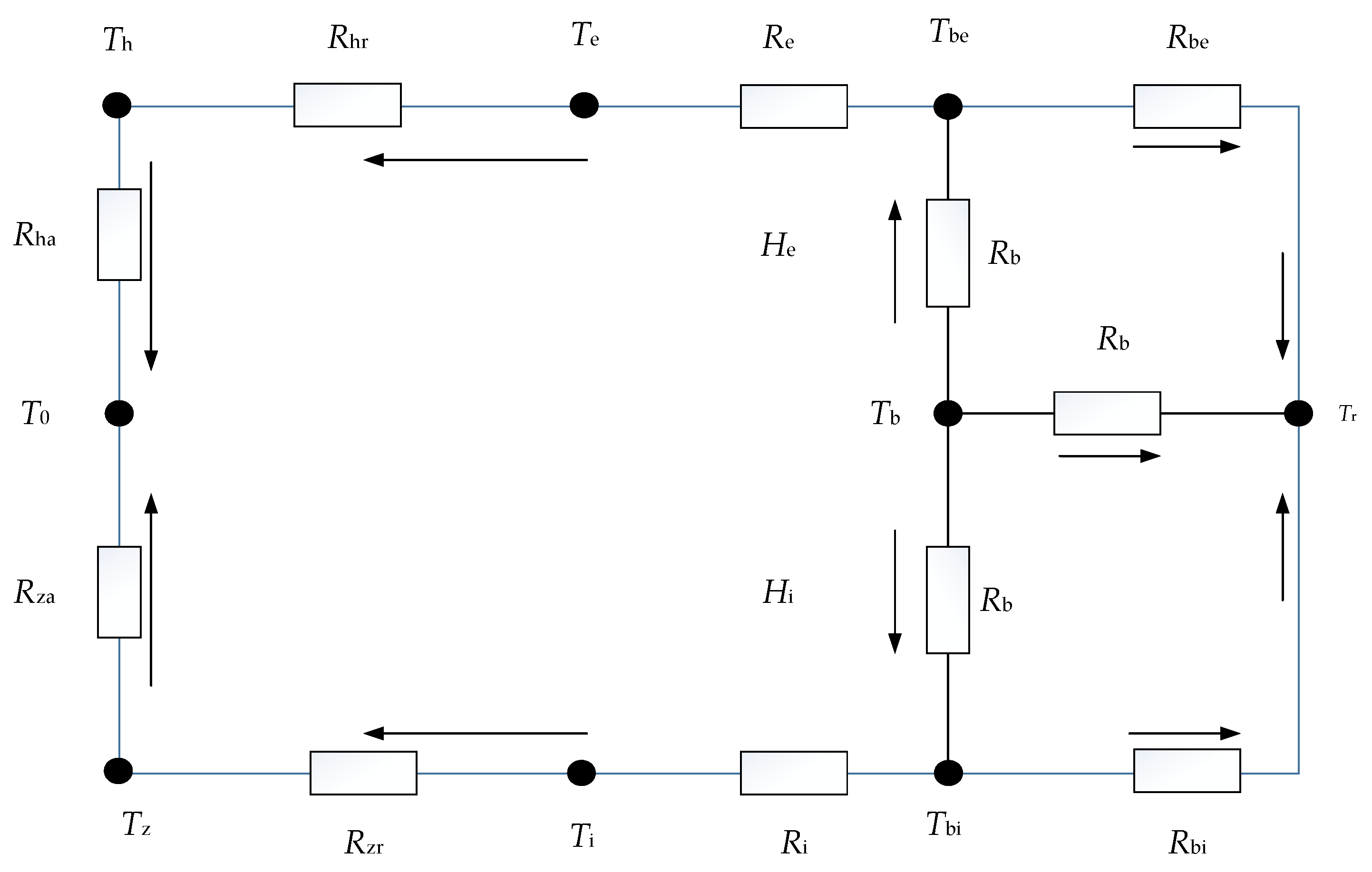
2.3. Temperature Calculation by Thermal Network Method

Using the theory of heat transfer and Kirchhoff’s law of energy conservation, the thermal network method is employed to determine the temperature. As illustrated in Figure 6, the thermal network grid method is employed to establish a temperature field model, formulate temperature node solution equations, and compute the bearing temperature. In Figure 7, the contact points between the bearing pedestal, inner ring, outer ring, main shaft, ball, inner ring and ball, and outer ring have been simplified as temperature nodes.
Based on Burton and Steph’s viewpoint, the friction heat generated by the bearing is equally distributed to the rolling elements and the ferrules, and the heat transfer equations are expressed as follows:
T z T 0 R za + T z T i R zr = 0
T i T z R zr + T i T bi R i = 0
T bi T i R i + T bi T r R ir + T bi T b R b = H i 2
T b T r R br + T b T be R b + T b T bi R b = H i + H e 2
T be T e R e + T be T r R er + T be T b R b = H e 2
T e T h R hr + T e T be R e = 0
T h T 0 R ha + T h T e R hr = 0
where T 0 and T r respectively represent the ambient temperature and lubricating oil inlet temperature.
The literature [24] contains information on heat transfer resistance. The convection heat transfer coefficient can be divided into three components: the forced convection heat transfer coefficient between the bearing seat and the air, between the main shaft and the air, and between the lubricating oil in the bearing, as shown below.
The coefficient of thermal convection between the bearing pedestal and the air can be expressed as follows:
k h = 9.7 W / ( m 2 K )
The coefficient of thermal convection between the main shaft and the air can be expressed as follows:
k z = 9.7 + 5.33 ( 25 π N / 6000 ) 0.8
The average coefficient of forced convection of lubricating oil in rolling contact bearing can be approximated as follows [25]:
k a = 0.0986 { N υ [ 1 ± D w cos ( a 0 ) d m ] } 0.5 λ P r 1 3
where λ represents the fluid thermal coefficient, and P r denotes the Prandtl number.

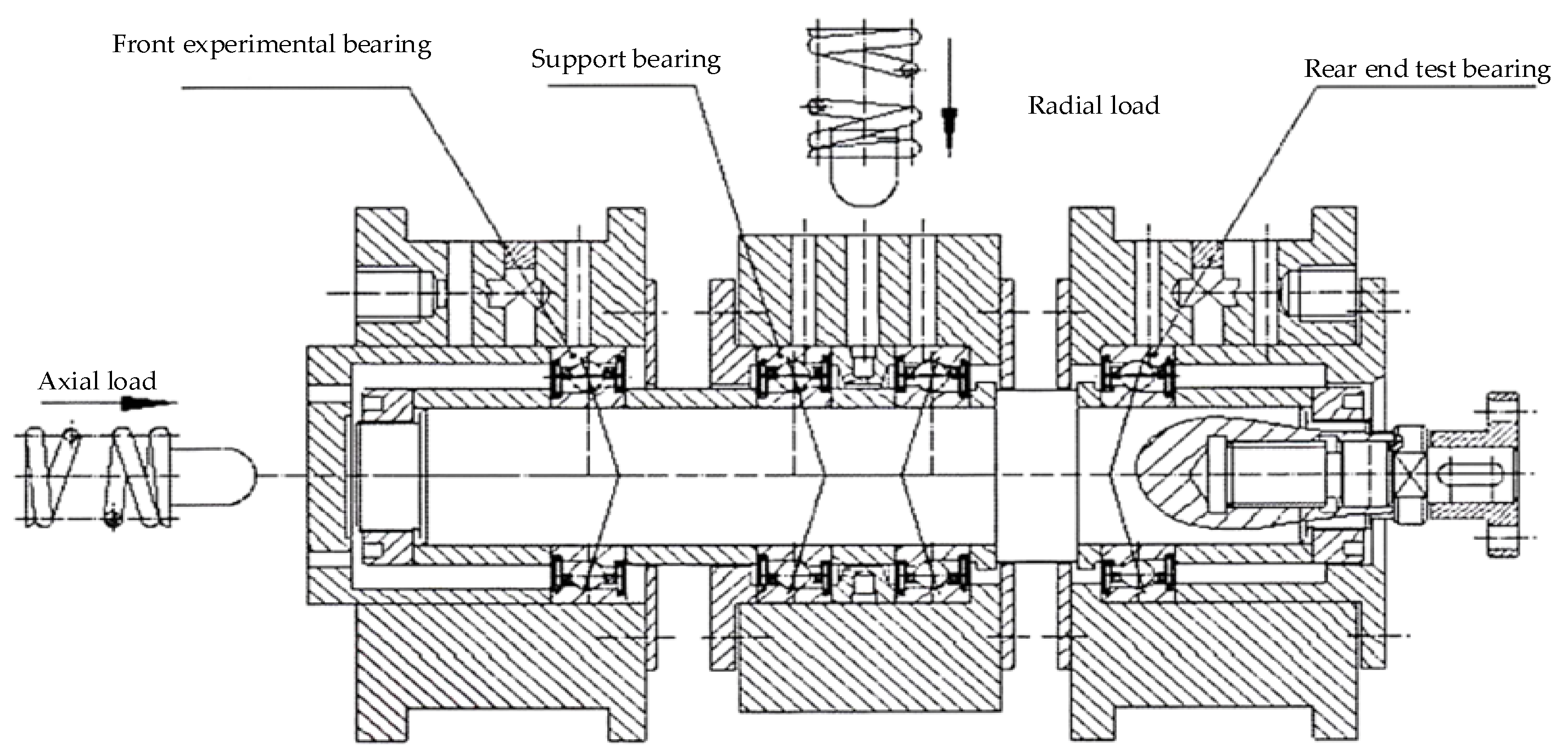
3. Comparative Verification

To validate the model, Figure 8 illustrates the test shaft system of the testing machine. Figure 9 illustrates its working principle. The loading mechanism of the test machine is capable of simultaneously applying axial and radial loads, with a maximum capacity of 1000 N, and the motor can reach a maximum speed of 36,000 r/min. The critical component of the test machine is the test bearing shaft system, with the ability to install four sets of bearings in each test. The bearings are divided into two end bearings and a central supporting bearing. Radial loads are applied to the supporting bearing and transmitted through the test shaft to the end bearings. Simultaneously, axial loads are applied to the front-end bearing and transmitted through the test bearing to the rear-end bearing. The test bearing is an H7006C ceramic ball bearing, featuring an accuracy class of P4. The parameters are presented in Table 1. The lubricating oil used is 4106 aviation lubricating oil, as illustrated in Table 2. The method of lubrication employed is oil injection lubrication. The bearing’s motion form involves the fixation of the outer ring and the rotation of the inner ring. During numerical simulation of the model, the external channel roundness error order is 2, the internal channel roundness error order is 3, and the internal and external channel roundness error amplitude is 0.3 μm.
The working condition is presented in Table 3. The experiment on bearing temperature measurement is conducted under five different working conditions. At an ambient temperature of 25 °C, the steps for temperature measurement are as follows: Firstly, the electric spindle is mounted onto the test bench, and the oil and gas apparatus, as well as the power supply, are connected. Subsequently, the data for axial and radial loading are transmitted through a pressure sensor to the control system. Next, a temperature sensor is inserted into the outer ring of the front-end bearing, and the collected temperature data are transferred to the computer control system. Figure 10 illustrates the interface of the test data acquisition instrument.
For a single operating condition, the temperature is collected every 10 min of operation, and if the value fluctuation is minimal, it is considered to have reached a steady state. The results obtained thus far are compared with those of the numerical simulation.
Figure 11 shows the comparison between the results of the bearing test and the calculation results. The figure reveals that the calculation results of the model established in this paper are essentially consistent with the test results. The maximum relative error occurs under condition 3, where the test temperature is 33.5 °C and the calculation model results are 31.7 °C. The error is 5.37%, which confirms the validity of the model in this paper.
The calculation results generally tend to be lower than the test results, as the oil inlet temperature in the established bearing steady-state heat generation model is a fixed value, failing to reflect the temperature change that occurs during the circulation of lubricating oil.

4. Calculation Results and Analysis

Using angular contact ball bearing 7008C as the research subject, its rated static load is 7.7 KN, the rated dynamic load is 11.5 KN, and the maximum speed is 40,000 r/min. Its primary structural parameters are displayed in Table 4. The material parameters are presented in Table 5. Ambient temperature is 20 °C. The lubricating oil selected is 4106 aviation power oil, and the oil injection lubrication method is adopted. The form of bearing movement is such that the outer ring remains stationary while the inner ring rotates, with the oil inlet temperature set at 20 °C.

4.1. Influence of Bearing Working Conditions on Overall Heat Generation of Bearings

Figure 12 shows the relationship between the rotational speed of the bearing and the total heat generation of the bearing under different outer ring groove roundness error orders when the axial load is Fa = 500 N and the outer ring groove circularity error amplitude is 0.5 μm. From the graph, it can be seen that the overall heat generation of the bearing linearly increases with the increase in speed. As the speed increases, the centrifugal force on the ball increases, resulting in an increase in sliding friction between the ball and the inner and outer contact areas, and a linear increase in overall heat generation.
Figure 13 illustrates the correlation between axial load and total bearing heat generation of the angular contact ball bearing under various outer channel roundness error orders, with the rotating speed set at 10,000 r/min and the outer ring channel roundness error amplitude measured at 0.5 μm. Figure 12 indicates that there is a gradual increase in overall bearing heat generation as the axial load increases. The increase in axial load inhibits the rotation of the bearing and also leads to an increase in the normal contact force between the bearing rolling elements and the inner and outer rings. This causes an increase in the friction moment in the contact area, resulting in an overall increase in heat generation. When the order of the outer channel roundness error is equal to the number of balls n/2 ± 2 (where n = 1, 2, 3, …), the contact point between the ball and the outer ring is near the peak or valley, resulting in a small contact area and a low average normal load on the ball. The overall friction torque is correspondingly reduced, so the overall heat generation of the bearing is lower than when the roundness error is not considered. When the order of the outer channel roundness error is equal to the number of balls (2n − 1)/4 ± 2 (where n = 1, 2, 3, …), the contact area between the rolling elements and the inner and outer channels is large, the average normal load on the balls is large, and the friction torque in the contact area increases accordingly, resulting in a higher overall heat generation of the bearing compared to the case without roundness error. Under the same axial load, the overall heat generation of the bearing fluctuates significantly as the order of the roundness error increases.

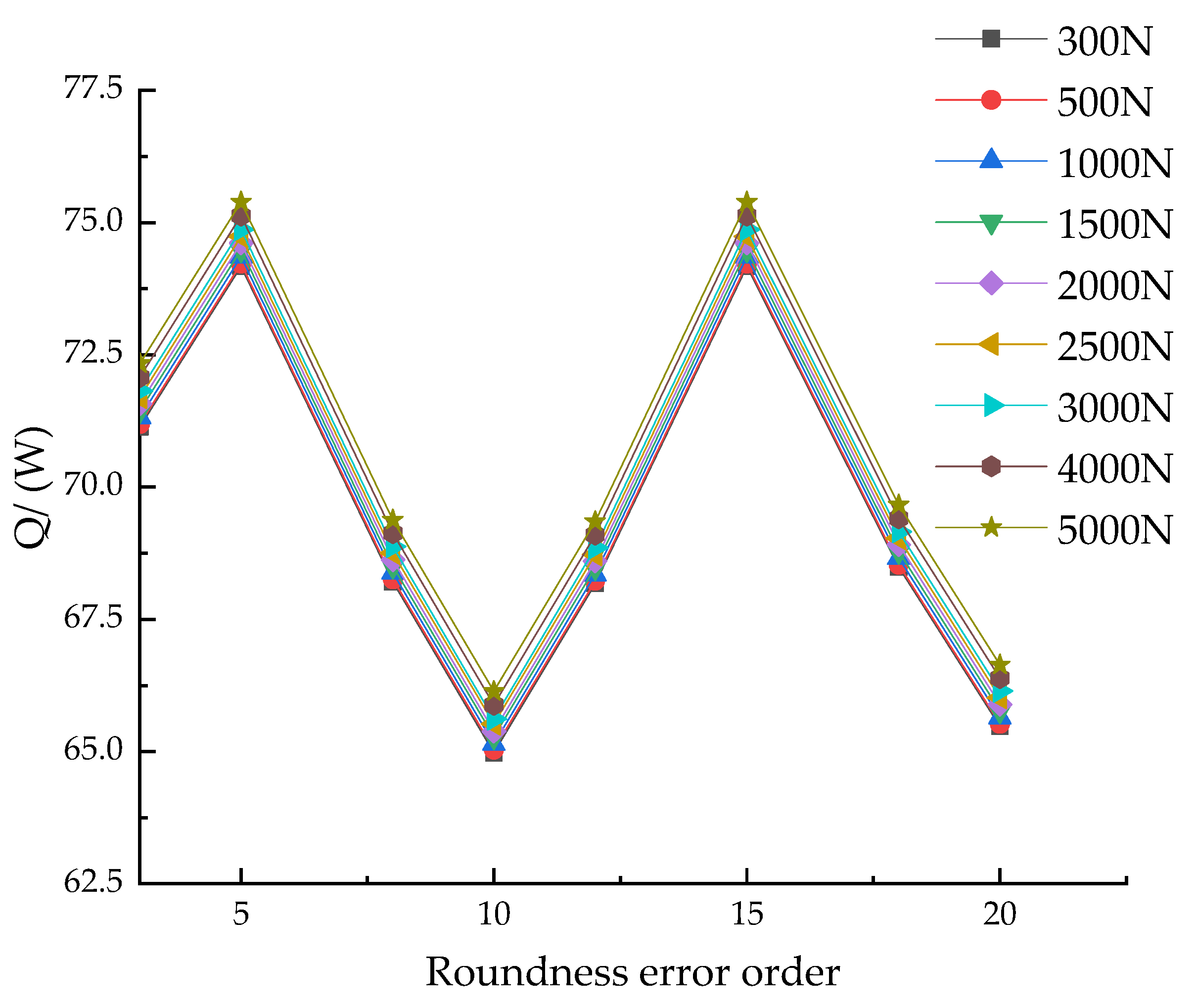
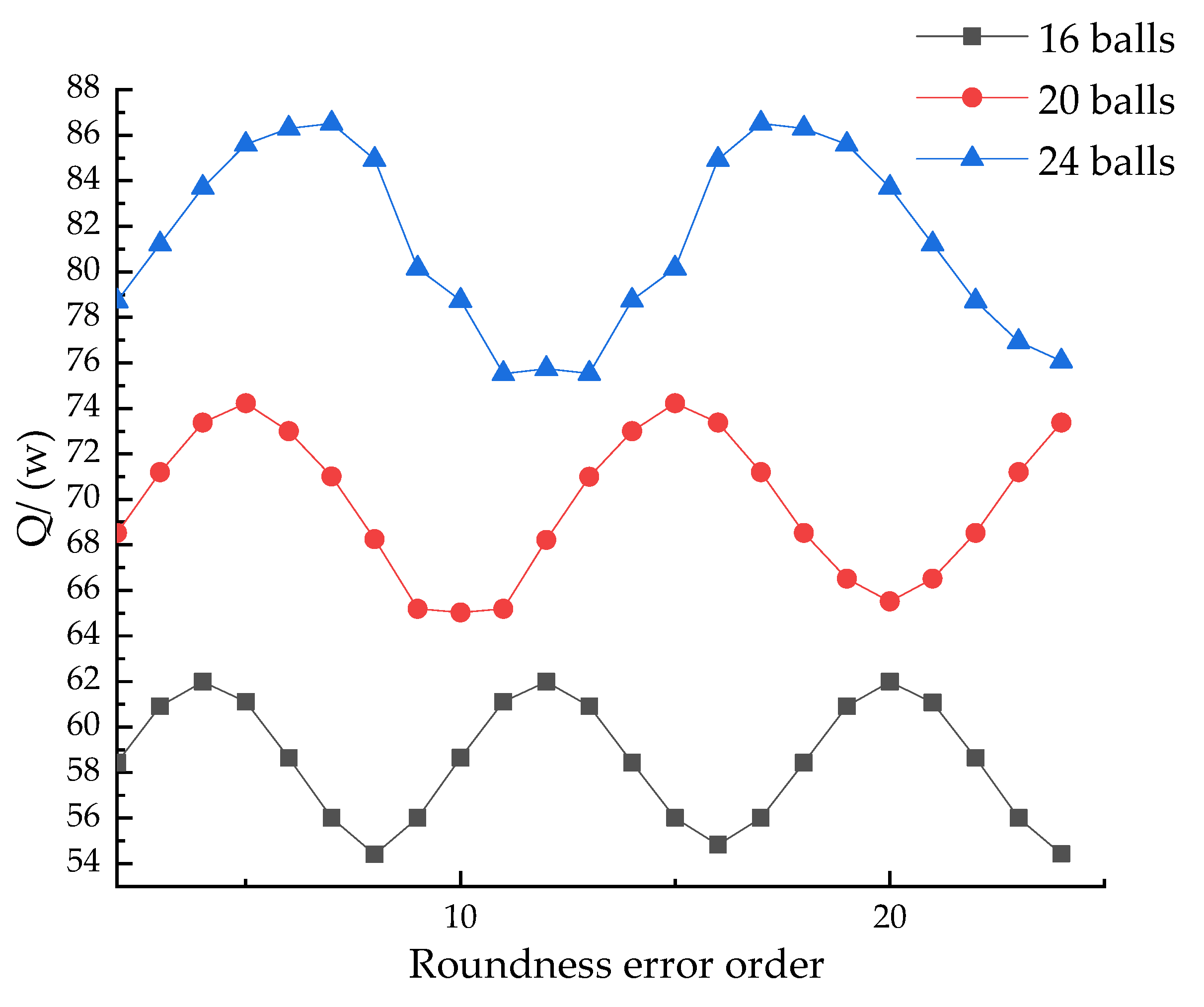
4.2. Influence of Roundness Error Order on the Whole Heat Generation of Bearings

Figure 14 shows that at a rotational speed of 10,000 r/min, the amplitude of the circularity error in the outer ring groove is 0.5 μm. The figure also illustrates the relationship between the circularity error of the outer ring groove and heat generation under various axial loads. As can be seen from the figure, as the order of the roundness error increases, the overall heat generation of the bearing fluctuates. When the order of the roundness error is equal to the number of balls (2n − 1)/4 times (where n = 1, 2, 3, …), the contact area between the ball and the raceway is maximized, and the spin friction power consumption generated between the ball and the inner and outer raceways is maximized, resulting in maximum overall friction torque and maximum overall heat generation of the bearing. When the order of the roundness error is equal to n/2 times the number of balls (where n = 1, 2, 3, …), the contact point between the ball and the outer raceway is at the peak or valley, at which point the contact area between the ball and the raceway, the deformation of the Hertz contact area, and the normal load on the ball are minimized, resulting in minimum friction torque and minimum overall heat generation of the bearing.
Figure 15 illustrates the relationship between the roundness error of the outer ring channel and heat generation under different rotational speeds, with an axial load of Fa = 500 N and outer ring channel roundness error amplitude of 0.5 μm. The figure illustrates that as the roundness error of the outer ring channel increases, it causes irregular changes in the contact area, resulting in fluctuations in the contact pressure and friction force, and consequently in heat generation. The faster the rotating speed, the greater the change in contact pressure and friction in the contact area, and the more pronounced the trend becomes.
In Figure 16, the relationship between the amplitude of the outer ring groove roundness error and heat generation is shown when the axial load is Fa = 500 N and the rotational speed is 10,000 r/min. As can be seen from the figure, the overall heat generation fluctuation of the bearing under steady state increases with the increase in the roundness error amplitude, and its fluctuation is proportional to the amplitude. The increase in the amplitude of the roundness error will lead to an increase in the unevenness of the radial clearance. When the magnitude of the roundness error increases, the non-uniformity also increases, resulting in a decrease in the radial clearance of the rolling elements. With the increase in the roundness error amplitude, the contact deformation also increases. As the roundness error order rises, the normal contact load exhibits fluctuating changes, and the intensity of these fluctuations is proportional to the roundness error amplitude. This is the primary factor causing fluctuations in heat generation. At specific orders, although the roundness error amplitude is particularly large, the overall force on the bearing is uniform, and the normal load is relatively small. Therefore, the overall heat generation is smaller. The amplitude of the circularity error selected in this article is intended to fully demonstrate its regularity. In practical work, excessive roundness error amplitude can compress the radial clearance, causing the bearing to fail to operate normally, and should be kept within a reasonable range. This phenomenon needs to be considered in the design and selection of bearings to ensure that the bearings can operate normally and maintain thermal balance during operation.
Figure 17 shows the relationship between the roundness error and heat generation of different numbers of balls when the axial load is Fa = 500 N and the rotational speed is 10,000 r/min. As can be seen from the figure, the overall heat generation of the bearing exhibits periodic changes with the increase in harmonic order of the outer ring groove roundness error. Under the same working conditions and roundness error, an increase in the number of balls will lead to an increase in the amount of heat generated, as the increased number of balls will result in an increase in the contact area between them, thereby generating more friction.

5. Conclusions

In this study, a thermal calculation model for angular contact ball bearings has been established based on the quasi-dynamic theory of bearings, the theory of elastohydrodynamic lubrication, the theory of heat conduction, and Kirchhoff’s law of energy conservation. The model considers the effects of roundness error, bearing preload, centrifugal effects, and thermal coupling. The influence of bearing raceway roundness error on the overall heat generation of the bearing has been analyzed. The following are the conclusions of this study:
(1)
As the speed and axial load increase, the overall heat generation linearly increases, and the increase in speed produces a more significant increase in heat generation compared to the axial load. When the order of the roundness error is equal to the number of balls n/2 ± 2 (where n = 1, 2, 3, …), the overall heat generation of the bearing is lower than when the roundness error is not considered. When the order of the roundness error is equal to the number of balls (2n − 1)/4 ± 2 (where n = 1, 2, 3, …), the overall heat generation of the bearing is higher than that without roundness error.
(2)
When the order of the roundness error is equal to the number of balls (2n − 1)/4 times (where n = 1, 2, 3, …), the overall heat generation of the bearing is maximum. When the order of the roundness error is equal to the number of balls n/2 times (where n = 1, 2, 3, …), the overall heat generation of the bearing is minimum.
(3)
As the order of the roundness error increases, the overall heat generation fluctuates. The faster the speed, the more obvious the trend of fluctuation. Under the same order of roundness error, the load has little effect on the overall heat generation, which increases with the increase in bearing speed.
(4)
The overall heat generation fluctuation of the bearing under steady state increases with the increase in the roundness error amplitude, and its fluctuation is proportional to the amplitude. The overall heat generation of the bearing exhibits periodic changes with the increase in the harmonic order of the roundness error, and the change period is mapped to the number of balls.

Author Contributions

Conceptualization, Y.Y.; methodology, Y.Y.; software, Y.Y. and R.M.; validation, Y.Y., Y.X. and Y.L.; formal analysis, Y.Y. and R.M.; investigation, Y.Y. and R.M.; resources, Y.Y., Y.X. and Y.L.; data curation, Y.Y. and R.M.; writing—original draft preparation, Y.Y. and R.M.; writing—review and editing, Y.Y., R.M. and Y.X.; visualization, Y.Y., R.M., Y.X. and Y.L.; project administration, Y.Y., Y.X. and Y.L. All authors have read and agreed to the published version of the manuscript.

Funding

This work was supported by the Ministry of Industry and Information Technology Special Projects (Grant No. TC220H05V) and also supported by Key Research Projects of Higher Education Institutions of Henan Province (Grant No. 22A460018).

Institutional Review Board Statement

Not applicable.

Informed Consent Statement

Not applicable.

Data Availability Statement

Data are contained within the article.

Conflicts of Interest

The authors declare no conflicts of interest.

References

  1. Palmgren, A. Ball and Roller Bearing Engineering; Svenska Kullager Fabriken (SKF) Industries Incorporation: Philadelphia, PA, USA, 1959. [Google Scholar]
  2. Harris, T.A.; Kotzalas, M.N. Advanced Concepts of Bearing Technology Rolling Bearing Analysis; CRC Press, Taylor Francis Group: New York, NY, USA, 2006. [Google Scholar]
  3. Kerrouche, R.; Dadouche, A.; Mamou, M.; Boukraa, S. Power Loss Estimation and Thermal Analysis of an Aero-Engine Cylindrical Roller Bearing. Tribol. Trans. 2021, 64, 1079–1094. [Google Scholar] [CrossRef]
  4. Pouly, F.; Changenet, C.; Ville, F.; Velex, P.; Damiens, B. Power loss predictions in high-speed rolling element bearings using thermal networks. Tribol. Trans. 2010, 53, 957–967. [Google Scholar] [CrossRef]
  5. Pouly, F.; Changenet, C.; Ville, F. Investigations on the Power Losses and Thermal Behavior of Rolling Element Bearings. J. Eng. Tribol. 2010, 224, 925–933. [Google Scholar]
  6. Zheng, D.; Chen, W.; Li, M. An optimized thermal network model to estimate thermal per formances on a pair of angular contact ball bearings under oil-air lubrication. Appl. Therm. Eng. 2018, 131, 328–339. [Google Scholar]
  7. Tarawneh, C.M.; Fuentes, A.A.; Kypuros, J.A.; Navarro, L.A.; Vaipan, A.G.; Wilson, B.M. Thermal Modeling of a Railroad Tapered-Roller Bearing Using Finite Element Analysis. J. Therm. Sci. Eng. Appl. 2012, 4, 031002. [Google Scholar] [CrossRef]
  8. Hong, Y.; Kou, W. Dynamic Simulation of the Slide Friction Heat Generation of Deep Groove Ball Bearing Based on Hertz Theory. Equip. Manuf. Technol. 2014, 12, 39–41. (In Chinese) [Google Scholar]
  9. Zheng, D.; Chen, W. Effect of structure and assembly constraints on temperature of high-speed angular contact ball bearings with thermal network method. Mech. Syst. Signal Process. 2020, 145, 106929. [Google Scholar] [CrossRef]
  10. Nicolás, J.A.M.; de León Hijes, F.C.G.; Alhama, F. Solution of temperature fields in hydrodynamics bearings by the numerical network method. Tribol. Int. 2007, 40, 139–145. [Google Scholar] [CrossRef]
  11. Dong, Y.; Ma, Y.; Qiu, M.; Chen, F.; He, K. Analysis and experimental research of transient temperature rise characteristics of high-speed cylindrical roller bearing. Sci. Rep. 2024, 14, 711. [Google Scholar] [CrossRef] [PubMed]
  12. Lei, J.; Su, B.; Zhang, S.; Yang, H.; Cui, Y. Dynamics-Based Thermal Analysis of High-Speed Angular Contact Ball Bearings with Under-Race Lubrication. Machines 2023, 11, 691. [Google Scholar] [CrossRef]
  13. Hassan, E. Rasheed, Effect of surface waviness on the hydrodynamic lubrication of a plain cylindrical sliding element bearing. Wear 1998, 223, 1–6. [Google Scholar]
  14. Rodionov, E.M. Moment Originating from Errors in the Form or Rolling Surfaces of a Ball Bearing; Technical Report FTD-HT-66-374; Foreign Technology Div.: Wright-Patterson AFB, OH, USA, 1966. [Google Scholar]
  15. Cui, L. Research on Dynamic Performances of High-Speed Rolling Bearing and Rotor System of Aeroenging. Ph.D. Dissertation, Harbin Institute of Technology, Harbin, China, 2008. (In Chinese). [Google Scholar]
  16. Zheng, H.; Wang, F.; Ji, B. The Study for Effect of Outer Race Waviness on the Dynamic Behavior of Cylindrical Roller Bearing. Mach. Des. Manuf. 2014, 12, 82–84+88. (In Chinese) [Google Scholar]
  17. Yang, M.; Lu, H.; Zhang, X.; Duan, M.; Bao, L.; Wang, B.; Wu, W. Influence of Surface Waviness of Journal and Bearing Bush on the Static Characteristics of Hydrodynamic Bearing. Processes 2021, 9, 110. [Google Scholar] [CrossRef]
  18. Liu, J.; Pang, R.; Xu, Y.; Ding, S.; He, Q. Vibration analysis of a single row angular contact ball bearing with the coupling errors including the surface roundness and waviness. Sci. China Technol. Sci. 2020, 63, 943–952. [Google Scholar] [CrossRef]
  19. Deng, S.; Li, X.; Wang, J.; Wang, Y.; Teng, H. Analysis on the friction torque fluctuation of angular contact ball bearings. J. Mech. Eng. 2011, 23, 104–112. (In Chinese) [Google Scholar] [CrossRef]
  20. Gao, Y.; Deng, S.; Zheng, C.; Liang, B.; Li, J. Experimental study on effects of groove waviness on ball bearing friction torque. Bearing 2009, 10, 41–44. (In Chinese) [Google Scholar]
  21. Liu, J.; Yan, Z.; Shao, Y. An investigation for the friction torque of a needle roller bearing with the roundness error. Mech. Mach. Theory 2018, 121, 259–272. [Google Scholar] [CrossRef]
  22. Burton, R.A.; Staph, H.E. Thermally activated seizure of angular contact bearings. ASLE Trans. 1967, 10, 408–417. [Google Scholar] [CrossRef]
  23. Deng, S.; Li, X.; Wang, J. Friction al Torque Characteristic of Angular Contact Ball Bearings. J. Mech. Eng. 2011, 47, 114–120. (In Chinese) [Google Scholar] [CrossRef]
  24. Ai, S.; Wang, W.; Wang, Y.; Zhao, Z. Temperature rise of double-row tapered roller bearings analyzed with the thermal network method. Tribol. Int. 2015, 87, 11–22. [Google Scholar] [CrossRef]
  25. Crecelius, W.J.; Pirvics, J. Computer Program Operation Manual on SHABERTH: A Computer Program for the Analysis of the Steady State and Transient Thermal Performance of Shaft-Bearing Systems; U.S. Air Force: Washington, DC, USA, 1976.
Figure 1. Flow chart of the calculation model for angular contact ball bearings considering roundness error.
Lubricants 12 00043 g001
Figure 2. Angular contact ball bearing coordinate system.
Lubricants 12 00043 g002
Figure 3. A model of an angular contact ball bearing with roundness error.
Lubricants 12 00043 g003
Figure 4. Balance diagram of ball force.
Lubricants 12 00043 g004
Figure 5. Cage frame force diagram.
Lubricants 12 00043 g005
Figure 6. Schematic diagram of bearing temperature nodes.
Lubricants 12 00043 g006
Figure 7. Schematic diagram of bearing heat transfer network.
Lubricants 12 00043 g007
Figure 8. Bearing testing machine.
Lubricants 12 00043 g008
Figure 9. Schematic diagram of working principle of testing machine.
Lubricants 12 00043 g009
Figure 10. Result acquisition instrument.
Lubricants 12 00043 g010
Figure 11. Result comparison chart.
Lubricants 12 00043 g011
Figure 12. Relationship between rotating speed and bearing heating under different roundness error orders.
Lubricants 12 00043 g012
Figure 13. Relationship between axial load and bearing heat generation under different roundness error orders.
Lubricants 12 00043 g013
Figure 14. Relationship between roundness error and heat generation under different axial loads.
Lubricants 12 00043 g014
Figure 15. Relationship between roundness error and heat generation under different rotating speeds.
Lubricants 12 00043 g015
Figure 16. Relationship between roundness error amplitude of the outer groove roundness error and heat generation.
Lubricants 12 00043 g016
Figure 17. Relationship between roundness error, the numbers of balls and heat generation.
Lubricants 12 00043 g017
Table 1. H7006C Parameters of ceramic ball bearing.
ParameterValue
Outside diameter (mm)55
Inner diameter (mm)30
Pitch diameter (mm)42.85
Number of balls18
Initial contact angle (°)16
Spherical diameter (mm)5.5
Width (mm)13
Inner race groove diameter (mm)39.927
Outer race groove diameter (mm)48.079
Cage pocket hole diameter (mm)5.89
Clearance (mm)0.15
Cage width (mm)8.8
Guide face diameter (mm)46.07
Ceramic thermal conductivity (W/(m·K))16.7
Table 2. Performance parameters of lubricating oil at normal temperature.
ParameterValue
Dynamic viscosity (Pa*s)0.055
Coefficient of viscous pressure (×10−8 Pa−1)1.85
Viscosity-temperature coefficient (°C−1)0.0315
Coefficient of heat transfer (W/(m·K))0.0966
Table 3. Test conditions.
Condition12345
Axial load Fa (N)300500200400600
Radial load Fr (N)200400100300500
Inner ring speed (r/min)6000600010,00010,00010,000
Elapsed time (min)1010101010
Table 4. 7008C bearing parameters.
ParameterValue
Outside diameter (mm)68
Inner diameter (mm)40
Pitch diameter (mm)53.98
Number of balls20
Initial contact angle (°)18
Spherical diameter (mm)6.35
Width (mm)15
Inner race groove curvature radius (mm)3.49
Outer race groove curvature radius (mm)3.3
Cage pocket diameter (mm)6.73
Cage pocket clearance (mm)0.19
Cage width (mm)10
Guide face diameter (mm)58.08
Table 5. Material parameters.
ParameterValue
Bearing Steel Modulus of Elasticity (N/m2)2.04 × 1011
Holder elastic modulus (Polyamide, N/m2)2.32 × 109
Bearing Steel Density (kg/m3)7805.6
Cage density (kg/m3)1120
Poisson’s ratio of bearing steel0.3
Cage Poisson’s ratio0.34
Heat conductivity coefficient of bearing steel (W/(m*K))40.1
Thermal expansion coefficient of bearing steel (1/°C)0.1224 × 10−4
Disclaimer/Publisher’s Note: The statements, opinions and data contained in all publications are solely those of the individual author(s) and contributor(s) and not of MDPI and/or the editor(s). MDPI and/or the editor(s) disclaim responsibility for any injury to people or property resulting from any ideas, methods, instructions or products referred to in the content.

