


Abstract
This paper presents a hybrid flux-frame high-frequency (HF) injection and model reference adaptive control (MRAC)-based sensorless rotor position and speed estimation scheme for advanced direct torque-controlled interior permanent magnet synchronous motor (IPMSM) drives. Unlike conventional stationary-frame (α-β) HF-injection methods, the proposed technique demodulates the injected high-frequency current directly in the stator-flux reference frame, yielding a saliency signal with reduced cross-coupling and improved estimation fidelity at zero and low speed. At medium-to-high speed, an adaptive MRAC estimator, driven by the stator-current error, provides back-EMF-based speed and angle estimation. A speed-dependent gating mechanism blends the two estimators, avoiding the discontinuous angle transitions typically introduced by hard-switched hybrid observers. The complete estimation and control algorithm, including a constant-switching-frequency torque regulator, is implemented and validated through processor-in-the-loop (PIL) co-simulation on a Texas Instruments LAUNCHXL-F280039C DSP-based microcontroller. Simulation and PIL results confirm the practical feasibility of the proposed hybrid estimation scheme, which offers reduced implementation complexity compared to Field-Oriented Control (FOC)-based sensorless techniques predominantly reported in the literature, since direct torque control (DTC) inherently avoids continuous coordinate rotation and current–vector modulation. Successful validation on the single-core, cost-effective LAUNCHXL-F280039C microcontroller, compared to higher-end dual-core DSP platforms (e.g., the F2837xD series) typically used in sensorless drive research, further demonstrates the suitability of the proposed approach for low-cost, resource-constrained embedded motor drive implementations.
1. Introduction
Direct torque control (DTC) has long stood out among control strategies for permanent magnet synchronous motor (PMSM) drives, not for mathematical elegance but for its fast torque response, delivered through a structure simple enough to reason about without continuous coordinate transformations. Ren, Zhu, and Liu showed that a simple duty-ratio regulator appended to the classical hysteresis DTC could suppress torque ripple without compromising its simplicity [1]. Mohan, Zhang and Foo extended this to the inverter side, exploiting the redundant vectors of a three-level NPC inverter to jointly reduce torque ripple and balance capacitor voltage [2], while Niu, Li and Wang achieved comparable ripple suppression through duty-ratio modulation with reduced parameter dependence [3]. Mohan, Zhang and Foo subsequently addressed the variable, EMI-complicating switching frequency inherent to hysteresis DTC through a constant-switching-frequency formulation for three-level NPC-fed IPMSM drives [4]. Shinohara et al. showed that the MTPA reference flux could be calculated directly rather than via an offline lookup table [5], and Mohan, Zhang and Foo later extended a related duty-cycle strategy specifically to low-speed operation [6], where classical DTC struggles as the back-EMF signal underlying much of its estimation vanishes. Wu and Narimani’s treatment of high-power converters [7] remains the foundation for converter design in this body of work. Naganathan and Srinivas emphasized that parameter sensitivity remains a persistent obstacle to dependable DTC deployment [8], which is an uncertainty that the sensorless-estimation literature, dominated by model reference adaptive system (MRAS)-based approaches, has sought to resolve. Wei et al. refined the adaptive mechanism to improve estimation accuracy [9], while Sharma and Bhattacharya’s wide-range encoderless DTC study [10] made explicit the asymmetry that back-EMF-based estimation performs well at medium-to-high speed but is structurally blind near standstill. Hakami and Lee improved torque capability over a wider range using a four-level hysteresis logic for three-level NPC-fed IPMSMs [11], and Sharma and Bhattacharya later embedded DC-link balancing directly into a sensorless three-level NPC drive [12], though the estimator itself remained a conventional back-EMF observer, offering little insight into standstill startup. Sun et al. coupled MRAS estimation with Grey Wolf optimization to improve convergence [13], and Nasr et al. refined duty-ratio regulation for torque quality in DTC-controlled PMSM drives [14]. Li, Hu and Shi’s review of position-sensorless compound control [15] reached the same conclusion echoed throughout this field: a physical mechanism independent of induced voltage is required near standstill, regardless of how well a back-EMF-based estimator performs once the rotor is moving. Elkholy et al.’s broader review of PMSM control techniques [16] reinforced that parameter sensitivity and low-speed uncertainty remain the two obstacles most stubbornly separating sensorless DTC from dependable industrial deployment, while Jnayah et al. showed that a modest restructuring of DTC switching logic could suppress common-mode voltage without sacrificing dynamic performance [17]. Krishnan’s foundational treatment of electric motor drives [18] and Bose’s classical text on power electronics and variable-frequency drives [19] continue to underpin nearly all of this work. At a broader level, Wang, Valla and Solsona’s survey of position-sensorless PMSM drives [20] confirms that hybrid schemes combining a saliency-based low-speed estimator with a back-EMF-based high-speed estimator have been developed almost exclusively within field-oriented control (FOC) frameworks; Kumar and Singh’s hardware-validated MRAC drive [21], for instance, achieves full-range sensorless operation through an I-f open-loop startup and a variable-switching-frequency predictive current controller, while Wang et al.’s HF square-wave injection scheme [22] targets the position-sensorless control of dual three-phase IPMSM drives, again within an FOC structure. None of these studies nor those surveyed above brings together a low-speed estimation mechanism independent of back-EMF, a smooth handover to a back-EMF-based estimator as speed increases, and a constant-switching-frequency torque regulator, within a single, DTC-based, embedded-hardware-validated design for a three-level NPC-fed IPMSM drive. It is this specific combination, summarized in Table 1, that remains absent from the literature. Motivated by this gap, the present work proposes a hybrid flux-frame high-frequency (HF) injection and model reference adaptive control (MRAC)-based sensorless rotor position and speed estimation scheme for a three-level NPC inverter-fed, direct-torque-controlled IPMSM drive operating under a constant-switching-frequency torque regulator. Unlike the stationary-frame injection techniques implicit in much of the sensorless literature surveyed above, the proposed method demodulates the injected HF current directly in the stator-flux reference frame, improving estimation fidelity precisely in the low-speed region where MRAS-based methods are known to be unreliable. A speed-dependent gating mechanism governs the transition to the MRAC estimator as speed increases, deliberately avoiding the abrupt, discontinuity-prone handovers that characterized many hard-switched hybrid observers. The complete scheme, including the constant-switching-frequency torque regulator, is implemented and validated through processor-in-the-loop testing on a Texas Instruments LAUNCHXL-F280039C DSP, which is a single-core, cost-effective platform that deliberately contrasts with the higher-end dual-core processors typically employed in comparable sensorless drive research. This choice of processor-in-the-loop verification, rather than hardware-in-the-loop or full experimental validation, is deliberate, not a matter of convenience. The principal risk introduced by the proposed scheme lies entirely on the control-algorithm side: the debounced hybrid switching logic that arbitrates between the HF-injection and MRAC estimators, and the carrier-based constant-switching-frequency torque regulator, must execute correctly within a fixed 50 μs sampling interval under single-precision, fixed-point-class arithmetic, compiler-generated code, and real interrupt latency, none of which are exercised by an idealized offline simulation. PIL directly targets this risk by compiling the complete control algorithm and executing it, unmodified, on the actual TI F280039C target in closed loop with a high-fidelity Simulink plant model, thereby exposing exactly the class of errors, timing violations, quantisation-induced instability, and adaptation law drift that would otherwise surface only after physical hardware is assembled. HIL testing, by contrast, is oriented toward validating the electromechanical plant-side dynamics sensor noise, mechanical coupling, and thermal behaviour under a real-time-emulated load; since the plant model employed here has already been extensively validated against the analytical machine equations in Section 2 and exercised across the full operating envelope in Section 7, the incremental verification value of HIL at this stage is limited relative to the risk PIL is specifically designed to close, namely confirming that the novel hybrid estimator-switching and constant-frequency torque-regulation algorithms are correctly realizable, in real time, on the target embedded hardware. This distinction also underscores a further contribution of the present work: to the authors’ knowledge, no prior DTC-based sensorless scheme in the literature surveyed above has been subjected to processor-in-loop verification of this kind, making the present real-time embedded validation a novel methodological contribution in its own right, independent of the control algorithm itself.
Table 1.
Comparative Overview of Sensorless Estimation Techniques in DTC Drives.
2. Mathematical Modelling of the IPMSM Drive System
The algorithm for the machine’s stator voltage is described as [7].
where λds and λqs are the dq reference frame flux linkages of the stator, respectively, which are as follows
Substituting Equation (2) into Equation (1), we have [16]
The variables mentioned above are defined by [16]
The electromagnetic torque produced by a synchronous motor can be represented as [16]
Substituting Equation (2) into (4), we obtain
The rotor speed ωr is governed by the motion equation, as shown by Equation (7),
For modelling and simulation, Equation (3) can be systematized as shown by Equation (8)
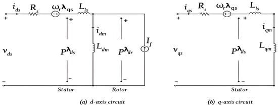
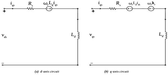
Figure 1 represents a generalized d-q reference frame of a PMSM in the concurrent frame. The equivalent circuit is based on the induction motor model with the modification of replacing ω with rotor speed ωr. With the inclusion of direct and quadrature-axis effects on the respective parameters, and the impact of the permanent magnet via a fixed source current, the following mathematical rearrangements are made to clarify the machine behaviour [7]. Figure 2 represents an elementary circuit for the synchronous machine, constructed from Equation (4).
Figure 1.
Simplified d-q axis representation of a machine in the concurrent frame of reference [7,21,22].
Figure 2.
Simplified d-q axis schematic of a machine in the concurrent frame of reference [7,21,22].
3. Constant-Switching-Frequency Three-Level DTC Implementation
This section presents the direct torque control (DTC) implementation for a three-level neutral-point-clamped (3L-NPC) inverter-fed IPMSM drive. The conventional switching-table-based DTC is first outlined, highlighting its limitations such as variable switching frequency and torque ripple. A constant-switching-frequency scheme is then introduced using a carrier-based torque controller. Additionally, redundant voltage vectors are used to maintain neutral-point voltage balance while improving torque performance.
3.1. Methodology of DTC
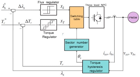
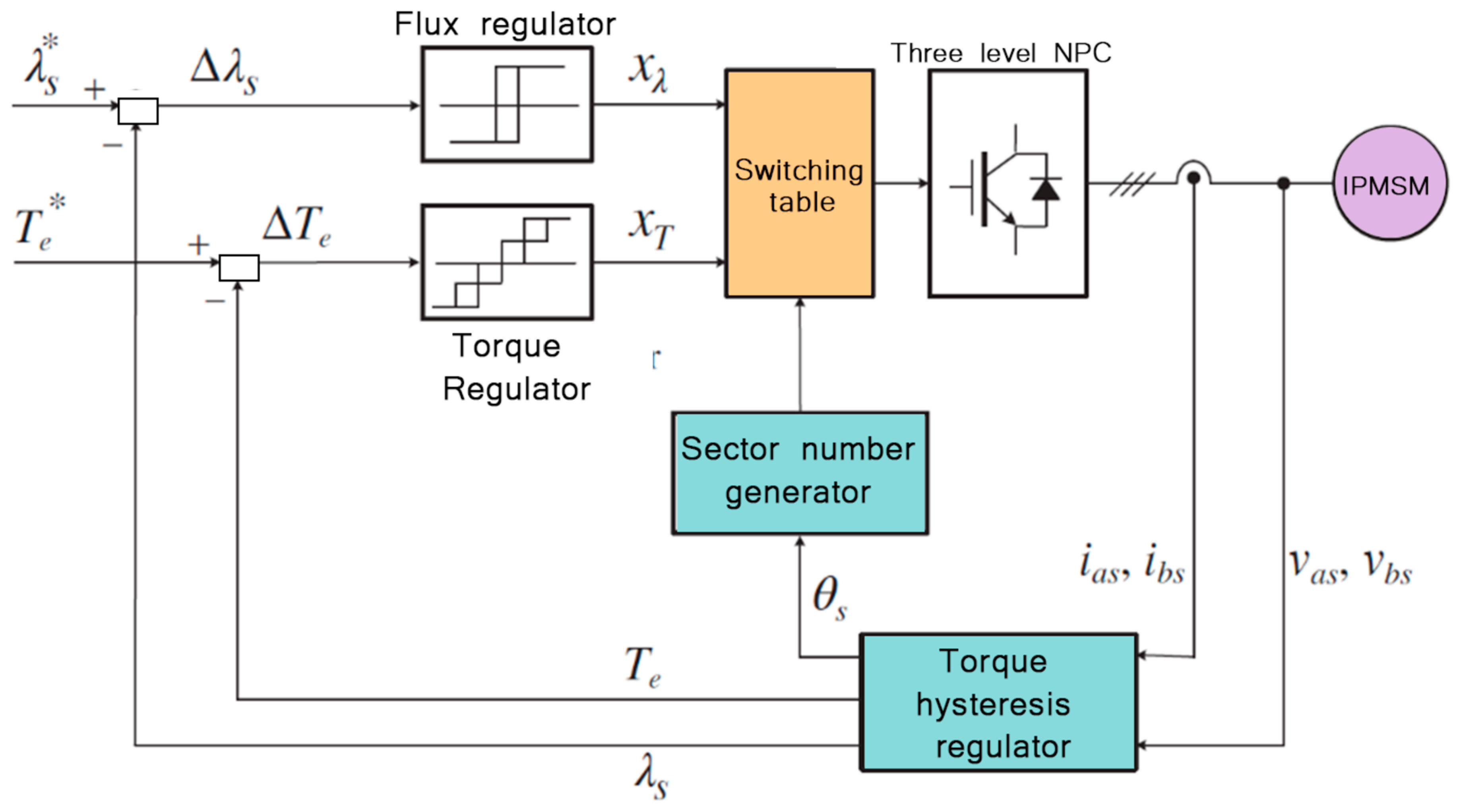
The three-level neutral-point-clamped (NPC) inverter produces large-, medium-, small-, and zero-voltage vectors, yielding 19 distinct switching states, including redundant vectors. The conventional DTC drive system, depicted in Figure 3, employs this inverter topology to feed the IPMSM [2,4,6]. When contrasted with the conventional two-level configuration, the availability of additional voltage vectors enables more accurate control of the stator-flux trajectory and torque dynamics. Small-voltage vectors and zero-voltage vectors exhibit redundancy, which can be exploited to control the neutral-point voltage without hindering the output voltage [7].
Figure 3.
Block diagram of conventional DTC scheme [7].
The torque and flux variation rates depend on the applied voltage vector, operating speed, and load conditions. At low speeds, the rate of torque variation is relatively high, leading to pronounced torque ripple in conventional DTC. The use of a three-level inverter enables the selection of voltage vectors with smaller torque slopes, thereby improving steady-state performance. * Reflecting reference term in the Figure 3.
3.2. Proposed Constant-Switching-Frequency Three-Level DTC
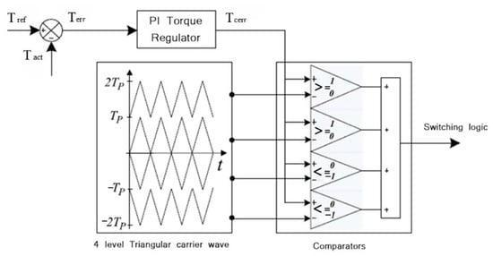
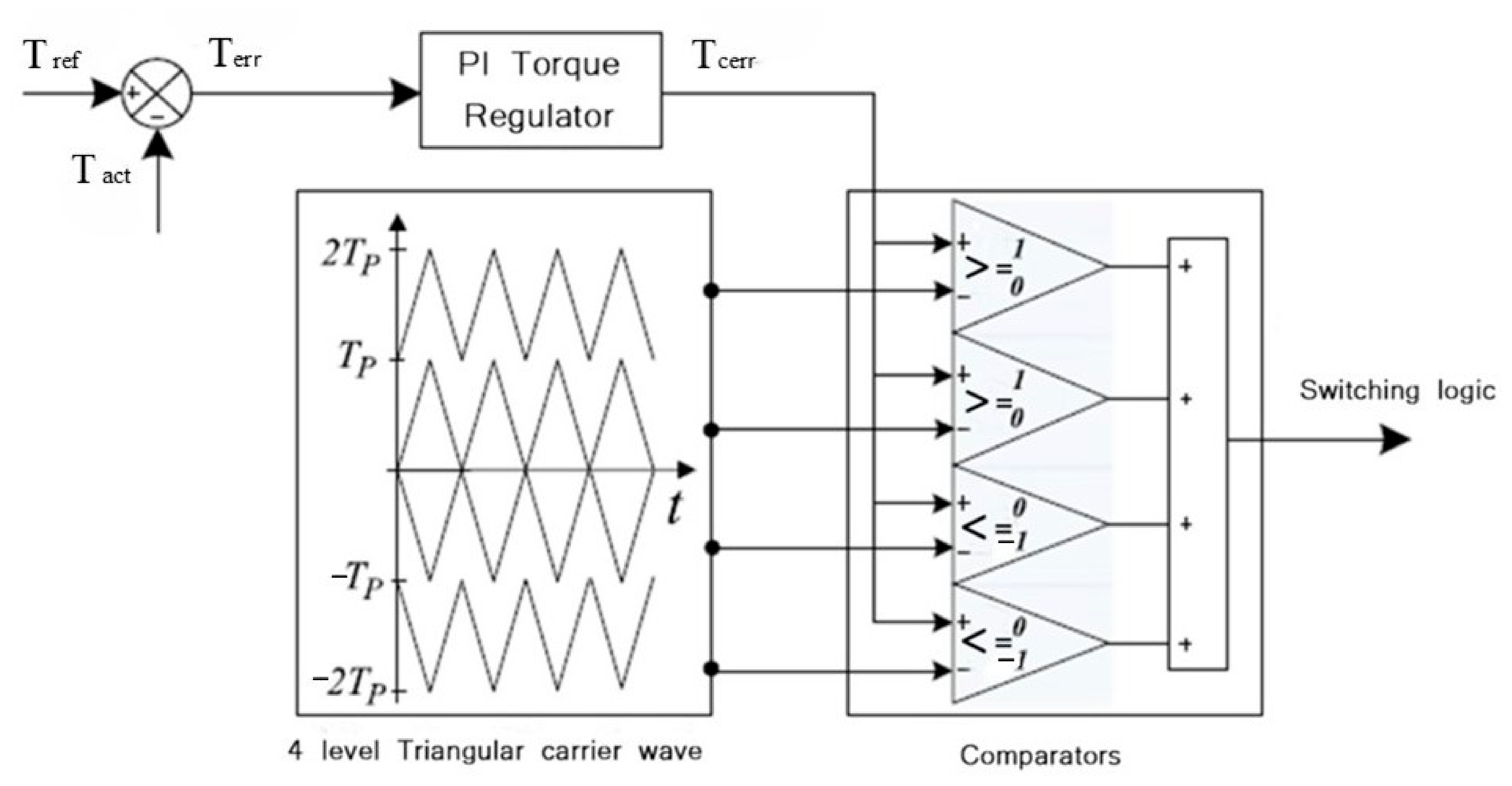
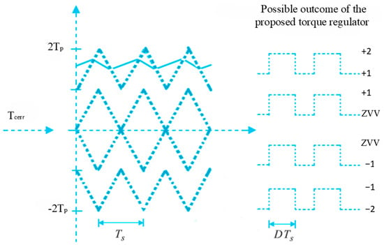
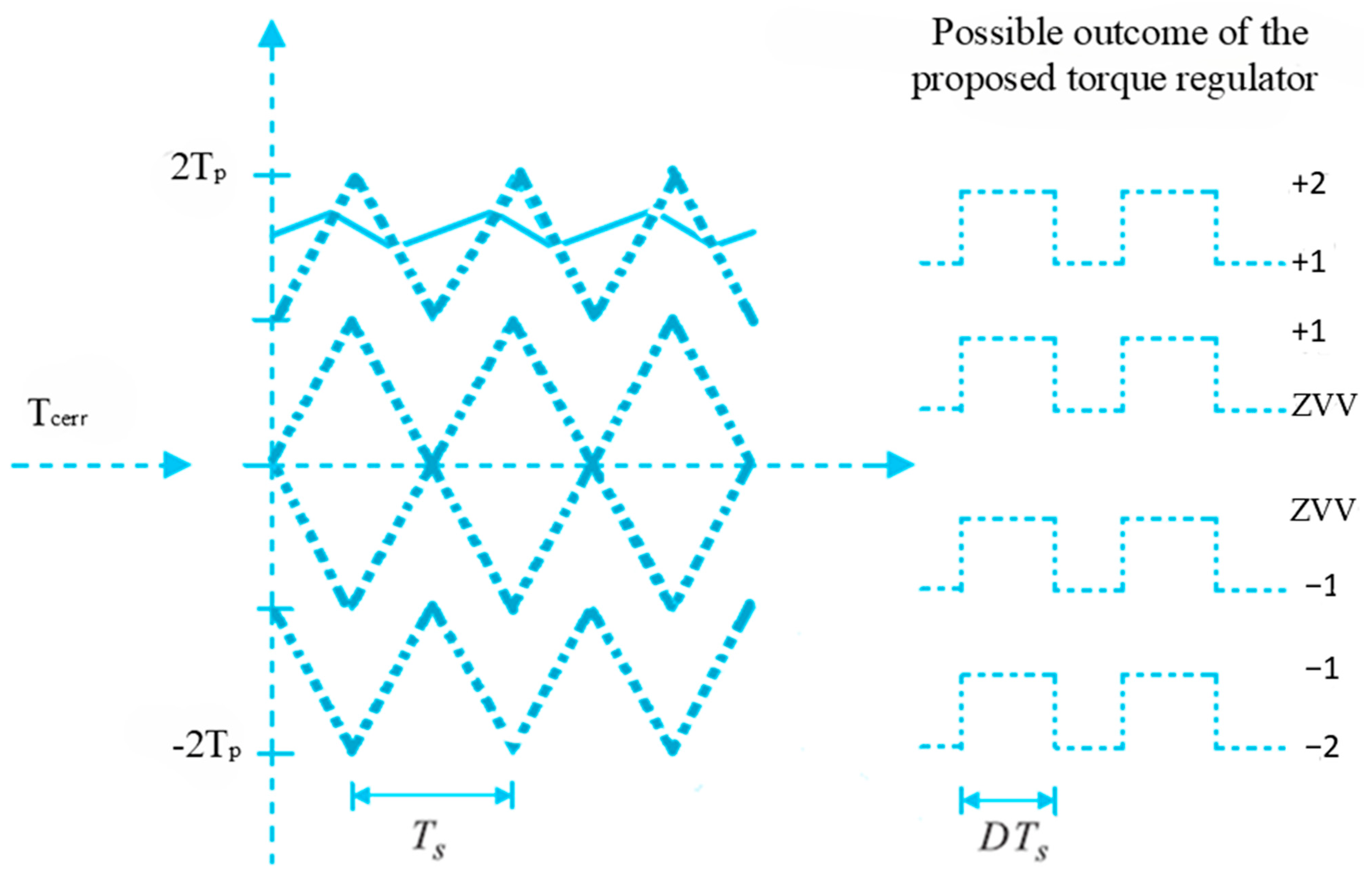
In the proposed control scheme, the conventional hysteresis-based torque comparator is replaced by a carrier-based torque comparator, as shown in Figure 4, to achieve constant-switching-frequency operation [4,6]. The regulator consists of a proportional–integral (PI) controller followed by multiple triangular carrier signals and comparators. This structure synthesizes multi-level torque commands, as shown in Figure 5, enabling the precise control of torque dynamics while maintaining a fixed switching frequency. Based on torque and flux demands and stator-flux sector information, a predefined switching logic identifies an appropriate voltage vector. For high-torque applications, large- or medium-voltage vectors are applied to maximize voltage utilization. Conversely, for low torque demand, small- or zero-voltage vectors are selected to minimize torque ripple. Within each switching cycle, two voltage vectors with different torque slopes may be applied sequentially, allowing fine adjustment of the average torque.
Figure 4.
Characteristics of proposed torque hysteresis [4,6].
Figure 5.
Expected output from torque regulator [2,4,6].
3.3. Neutral-Point Voltage Balancing and Smooth Switching
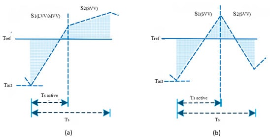
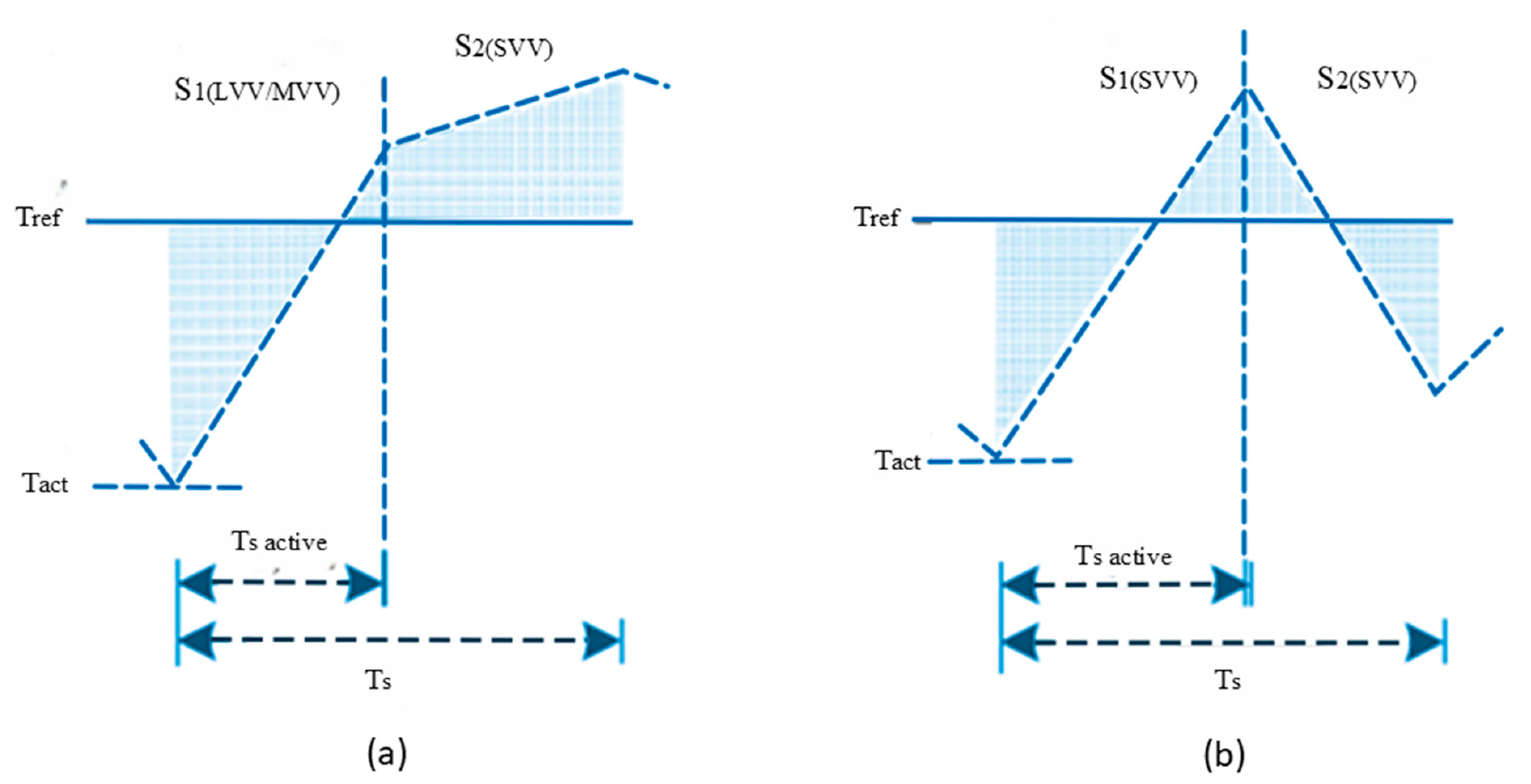
Neutral-point voltage imbalance is a critical issue in three-level NPC inverters, arising from unequal charging and discharging of the DC-link capacitors. In the proposed scheme, the redundancy of small-voltage vectors is utilized to mitigate neutral-point voltage fluctuations, as shown in Figure 6 [2]. The selection of redundant vectors is based on the polarity of the neutral-point voltage and current, ensuring balanced capacitor voltages over a switching cycle, as given in the supplementary material under Tables S1 and S2. The DC-link capacitor voltages are measured, while the neutral-point current is estimated from the applied voltage vectors. At low operating speeds, SVVs dominate the switching cycle, allowing the redundancy-based balancing to be exercised more frequently. As speed increases, LVVs and MVVs are applied more frequently to compensate for the growing back-EMF, while the controlled selection of redundant SVV states maintains adequate voltage balance, as shown in Figure 6a,b, respectively. To further reduce torque and flux ripple within each switching cycle, a duty-cycle control strategy is incorporated, following the approach of Mohan et al. [6], wherein the active and passive vectors are proportioned according to a duty ratio derived from the instantaneous torque error rather than being applied for the full cycle duration, allowing constant-switching-frequency operation to be preserved while the discrete torque steps of the switching table are smoothed. Smooth voltage-vector switching is enforced by restricting transitions to only adjacent vectors, reducing switching stress and avoiding large voltage jumps at the motor terminals, thereby improving reliability and electromagnetic compatibility [2]. When a direct transition between consecutive vector combinations would violate this criterion, an intermediate vector combination is inserted for one switching cycle to smooth the transition. Together, these measures suppress capacitor voltage deviations, reduce torque ripple, and maintain smooth vector transitions across the operating speed range, confirming the practical suitability of the proposed approach for medium- to high-power drive applications.
Figure 6.
Variation in torque ripple when (a) combining LVV/MVV with SVV as the passive vector, and (b) SVV with ZVV as the passive vector [4,6].
4. Sensorless Rotor Speed Estimation Using Stator-Current MRAC
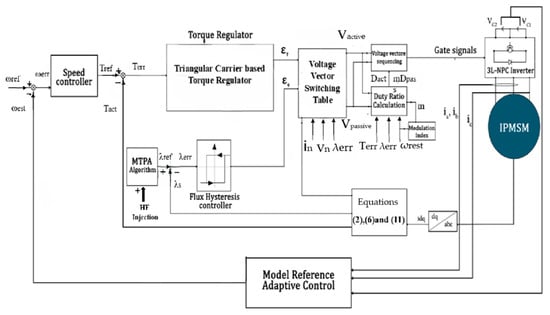
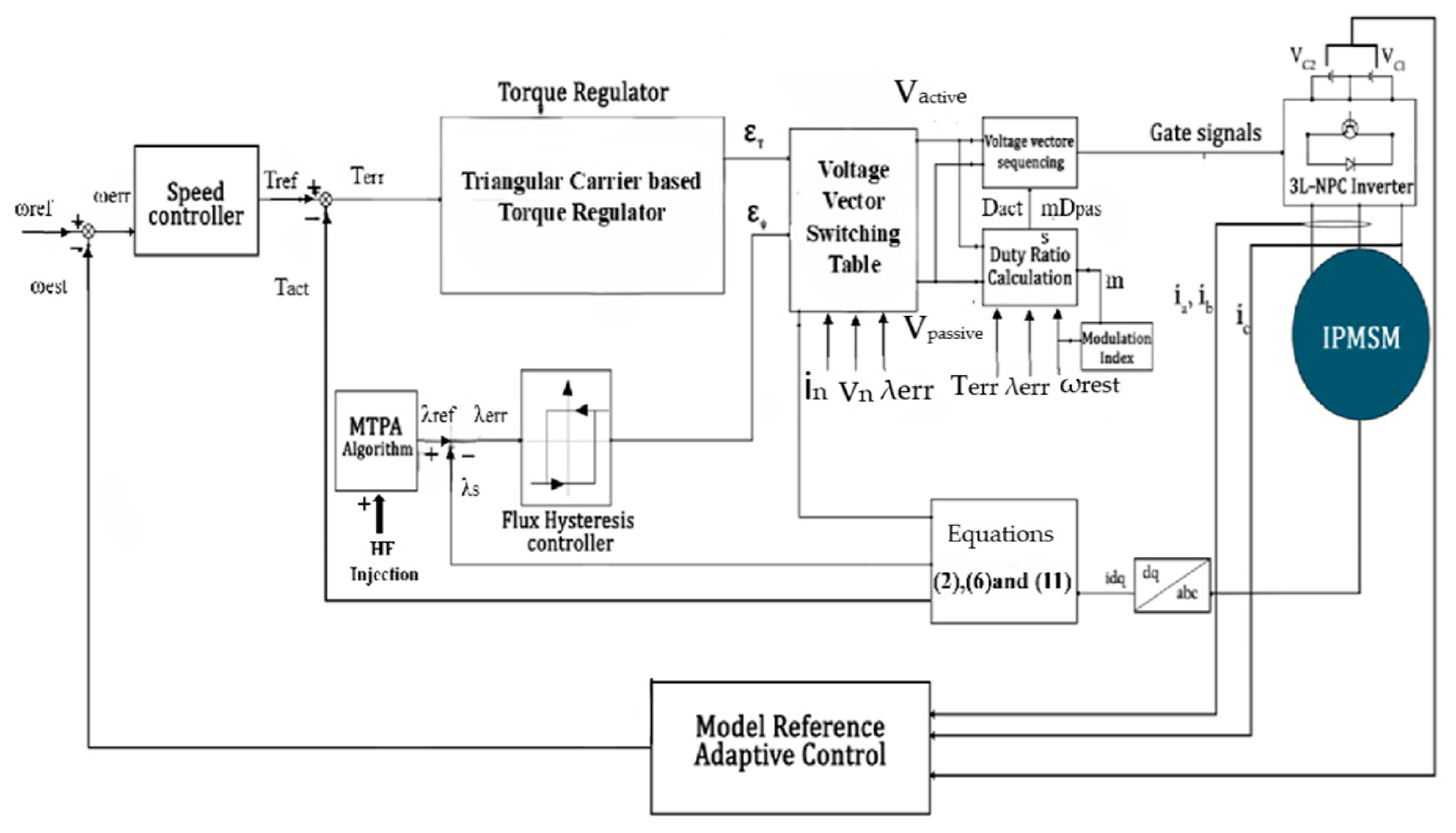
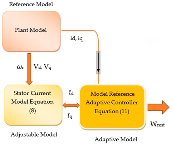
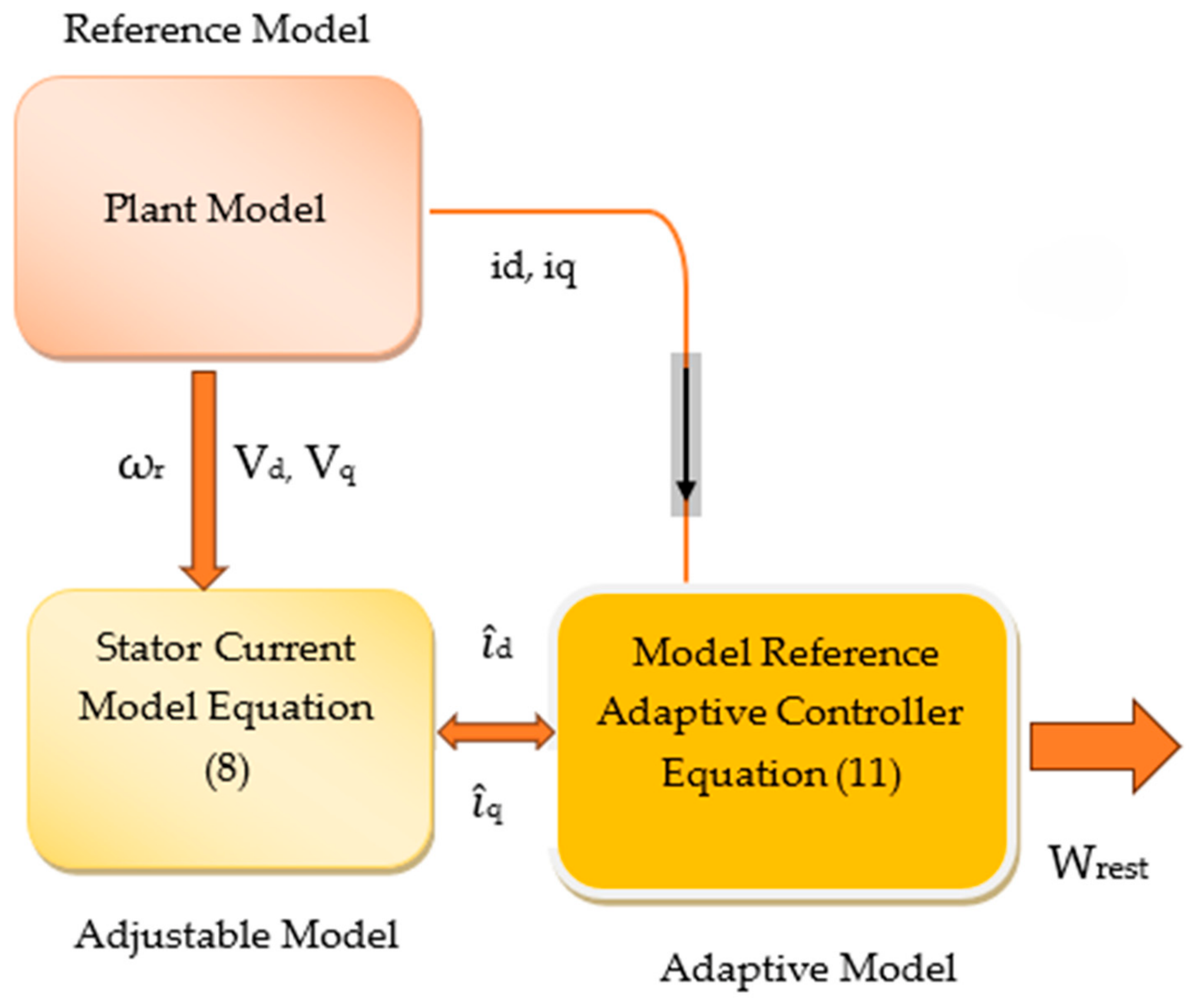
Reliable knowledge of the rotor speed is indispensable for stator-flux orientation, torque regulation, and reference-current generation in a direct-torque-controlled IPMSM drive. To remove the mechanical speed transducer while retaining accurate closed-loop behaviour, a stator-current-based model reference adaptive control (MRAC) estimator is embedded in the proposed constant-switching-frequency DTC framework as shown in Figure 7 [9,10,12]. The scheme derives the rotor speed solely from the measured phase currents and the reconstructed stator voltages, and therefore requires neither an encoder nor a dedicated voltage sensor. The estimator is organized around two current models operating in the synchronous reference frame, as shown in Figure 8. The reference model is the machine itself: the measured dq-axis stator currents, obtained through Park transformation of the sensed phase currents, inherently embody the true electromagnetic dynamics of the drive under DTC switching. The adjustable model, in contrast, reconstructs the same dq currents from the discretized voltage equations of the IPMSM, in which the rotor speed is the sole unknown to be identified.
Figure 7.
Proposed structural architecture of the DTC-MRAC system [8,9,10,12].
Figure 8.
Model reference adaptive controller for speed estimation [10].
The current derivatives that define the adjustable model are expressed as follows [7,10]:
The difference between the currents produced by the reference and adjustable models forms an adaptation error. This error is processed by a proportional–integral adaptation law, which continuously adjusts the estimated speed until the two models coincide. The estimated rotor speed is obtained as [10,12]
where the proportional term sharpens the transient response during the rapid torque excursions characteristic of DTC, while the integral term drives the steady-state estimation error to zero. Machine parameters are treated as known nominal constants; unlike a full parameter-adaptive observer, the present estimator identifies only the rotor speed, which keeps the adaptation law well-conditioned and computationally light for real-time execution on a fixed-point-class digital controller. The reconstructed stator voltages required by the adjustable model are computed from the inverter switching states and the measured dc-link voltage, so that the complete estimator relies exclusively on quantities already available in the drive. To suppress the high-frequency ripple introduced by DTC switching and the superimposed injection signal into the raw speed estimate, a two-stage low-pass filter is applied to the MRAC output before the signal is used for feedback.
Stability Analysis of the MRAC-Based Speed Estimator
The stability of the proposed MRAC speed estimator is established using Lyapunov’s direct method, applied directly to the reference and adjustable current models and the cross-product adaptation law of (15). The reference model, representing the true machine dynamics, is
while the adjustable model, using the estimated speed , is
Defining the current estimation errors, ed, eq and the speed estimation error as
and subtracting the adjustable model from the reference model gives the error dynamics
Using the identities
The error dynamics simplify to
A positive-definite Lyapunov function candidate is chosen as
where γ > 0 is the adaptation gain. Differentiating along the system trajectories gives
Substituting the error dynamics above yields
The proposed adaptation law, given in (15), uses the cross-product error
which, on substituting îd = id − ed and îq = iq − eq, reduces to the equivalent error-linear form:
Selecting the adaptation law as = γLqε, equivalent to the integral term Ki in (15), with the proportional term Kp providing additional transient damping without affecting the sign-definiteness argument below, gives
Substituting this adaptation law into the expression for cancels the leading -dependent term exactly when Ld = Lq (a non-salient, surface-mounted machine), leaving
For the IPMSM considered in this work, rotor saliency means Ld ≠ Lq, so a residual coupling term Δ remains, bounded as:
This residual term is quadratic in the error variables (a product of an error and either a bounded speed/estimate or a bounded current), whereas the leading term −Rs (ed2 + eq2) is likewise quadratic but scaled by the stator resistance and unaffected by the machine’s saliency ratio. Since the drive operates within finite voltage and current limits, and id remain bounded throughout normal operation, and Δ is therefore dominated by the negative-definite term whenever the error magnitudes are sufficiently small:
This establishes that the origin (ed, eq, omega-tilde) = (0,0,0) is locally asymptotically stable, with the region of attraction growing as the saliency ratio (Lq − Ld) decreases; for a non-salient machine, the residual term vanishes identically, and global asymptotic stability follows directly from LaSalle’s invariance principle. This distinction—between exact global stability for Ld = Lq and local, saliency-bounded stability for the IPMSM case—is consistent with the standard treatment of MRAS-based estimators for salient-pole machines, and is corroborated by the estimator’s observed convergence behaviour in both simulation and PIL execution, where the speed error is shown in Section 7 to converge and remain bounded within a small neighbourhood of zero across the entire operating range, including the transition through standstill.
5. MTPA-Based Flux Reference Generation for IPMSM Drives
To improve efficiency in the constant-torque region, a maximum-torque-per-ampere (MTPA) strategy is integrated into the proposed control framework. Due to rotor saliency in IPMSM, the electromagnetic torque consists of both magnetic and reluctance torque components. By appropriately selecting the d-axis and q-axis current components, the required torque can be produced with minimum stator-current magnitude. The MTPA algorithm generates optimal current references for determining the reference stator-flux magnitude in the DTC scheme. As a result, copper losses are reduced, and overall drive efficiency is improved, particularly under partial-load conditions [5].
The permanent magnet flux linkage λs can also be governed, which is [5,7]
λs = λds + jλqs = (Ldid + λr) + j(Lqiq)
From (6), the relationship between id and iq for MTPA control is derived as follows [5,7]
In IPMSM, id cannot be positive because Lq is larger than Ld.
This relationship can be rearranged as
where
γD = λrId (Lq − Ld)
On the other hand, λs can be calculated as follows [5,7]
where
6. High-Frequency Injection for Low-Speed Sensorless Operation
The HF-injection observer remains reliable down to standstill but introduces unnecessary losses and torque ripple if retained at higher speeds, whereas the MRAC estimator is accurate at higher speeds but loses observability as the back-EMF approaches zero near standstill. Since neither estimator is adequate across the entire operating range on its own, a debounced handover strategy is used to combine both, as detailed below.
6.1. Flux-Frame High-Frequency Demodulation
The three-phase stator currents are transformed to the stationary α–β frame:
The injected high-frequency carrier is generated directly from the simulation time as
C(t) = cos(wht), wh = 2πfh
A flux-frame current component, referenced to the estimated stator-flux angle θs, is computed by projecting the α–β currents onto the axis orthogonal to θs:
iqflux = −iαsinθs + iβ cosθs
This projection carries both the fundamental current component and the superimposed high-frequency saliency response. Its fundamental content is separated using a first-order low-pass filter with coefficient a_iq = 0.015, and the residual high-frequency component of the signal that actually encodes rotor saliency, followed by subtraction:
This high-frequency component is synchronously demodulated by multiplying it with the injected carrier, a standard technique that shifts the saliency-modulated signal to baseband, since the carrier and the saliency response share the same frequency ωh. The demodulated product is then low-pass filtered with coefficient aε = 0.008 to reject the double-frequency ripple inherent to synchronous demodulation, leaving an envelope ε proportional to the instantaneous flux-angle error:
d = iq,hf ∗ c(t), ∈←∈ + 0.008(d − ∈)
The flux-angle correction is obtained by scaling ε with the demodulation gain Gδ, which converts the (dimensionless) demodulated current envelope into an angle correction consistent with the machine’s saliency ratio; a further smoothing filter with coefficient a_d = 0.02 suppresses residual high-frequency content before the correction is applied:
The corrected rotor angle estimate is then obtained by subtracting this correction from the stator-flux angle:
6.2. PLL-Based Angle and Speed Tracking
The corrected angle θraw obtained above is inherently noisy, owing to the cascaded filtering and the residual carrier ripple that synchronous demodulation cannot fully eliminate. A phase-locked loop (PLL) is therefore used to produce a smooth angle and speed estimate. The wrapped tracking error between θraw and the current PLL angle estimate θ is computed using the four-quadrant arctangent of the sine and cosine of their difference, which avoids the 2π discontinuity that a direct subtraction would introduce:
eθ = atan2(sin (θraw − θ), cos(θraw − θ)
A proportional–integral controller drives this error toward zero, with both the integral term and the total output limited to ±400 rad/s to prevent windup during large transient errors such as those encountered at the initial estimator convergence:
winj ←sat±400(wint+ Kp,PLL eθTs)
The PLL angle is then integrated forward using this speed estimate and wrapped to [0, 2π) to maintain a bounded angle representation suitable for the six-sector switching-table lookup:
θ ← (θ + winjTs) mod2π
This yields the injection-mode estimates θinj = θ and ωhybrid = ωinj, which serve as the control feedback whenever the drive operates under HF-injection.
6.3. Debounced Estimator Handover
At startup, the drive is held under HF-injection control for a forced interval t < t_hf, min, allowing the PLL sufficient time to converge before any transition is evaluated. Beyond this interval, the handover decision is made once per control sample, indexed by the discrete sample index k (i.e., at the execution of the control algorithm every sampling period Ts). A counter cnt[k] tracks the number of consecutive samples for which the magnitude of the MRAC speed estimate, |est[k]|, has remained above the threshold ωthr:
At each sample, if the MRAC speed estimate exceeds ωthr, the counter is incremented by one relative to its previous value, cnt[k − 1]; if the estimate falls at or below ωthr even momentarily, the counter is reset to zero. This construction ensures that cnt[k] only accumulates during an unbroken run of samples above the threshold, so that a single transient dip discards all prior progress and only a genuinely sustained rise in speed can drive the counter to a large value—a deliberate design choice that rejects the transient MRAC spikes visible during the low-speed startup transient without requiring a separate filtering stage.
The estimator-latch state s[k] ∈ {0,1}, where s[k] = 1 denotes MRAC control and s[k] = 0 denotes HF-injection control, is then determined as
S[k] = {1, cnt[k] ≥ Nhold}
s[k − 1], otherwise
s[k − 1], otherwise
The transfer to MRAC control is committed only once the counter has reached the debounce length Nhold = 2000 samples, meaning the speed has remained above ωthr for Nhold consecutive samples; this rejects brief threshold crossings caused by torque or load transients that do not represent a genuine, sustained change in operating speed. Once this condition is satisfied and s[k] is set to one, the latch is retained for the remainder of the operating run: the construction above contains no mechanism by which s[k] reverts to zero, so the handover from HF-injection to MRAC is one-directional once the debounce criterion has been met. Prior to latching, s[k] simply holds its previous value whenever the debounce condition is not yet satisfied, which is what produces the brief, self-resolving excursions of s[k] observed during the transition window in Section 7 as the counter accumulates and resets before finally reaching Nhold.
The control estimates used by the drive are then selected according to the handover state:
Together, the debounce counter and one-directional latching logic ensure reliable, glitch-free position and speed feedback during the transition from standstill, through the low-speed HF-injection region, to steady-state MRAC operation. This strategy is validated in simulation and further confirmed through a processor-in-the-loop (PIL) implementation on the target microcontroller, as described in Section 8.
7. Simulation Results and Performance Evaluation
The proposed sensorless drive is evaluated under two representative operating scenarios that reflect its intended application as a low-speed sensorless backup for encoder-equipped EV traction drives. The first scenario examines steady, low-speed sensorless tracking, which is the core contribution of this work and the region where model-based estimators alone are inadequate. The second scenario assesses robustness to a load-torque reversal at constant speed, demonstrating that the estimator maintains accurate speed tracking when the torque demand changes sign. Both scenarios are first validated in simulation, and then constant-speed operation is confirmed on the F280039C through process-in-the-loop validation.
7.1. Case I—Constant Low-Speed Sensorless Operation
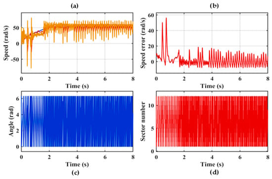
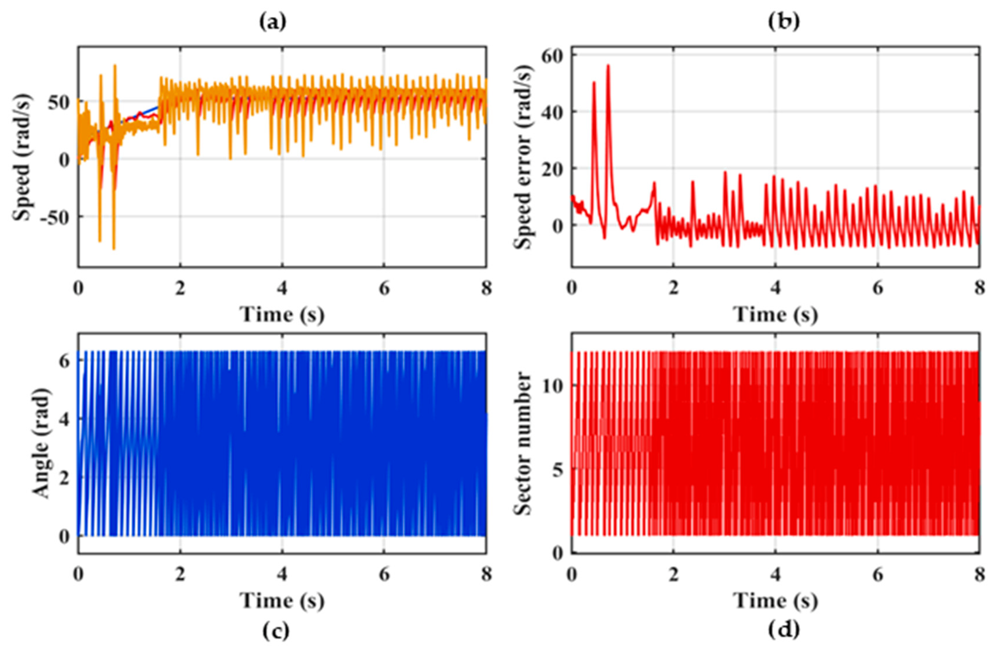
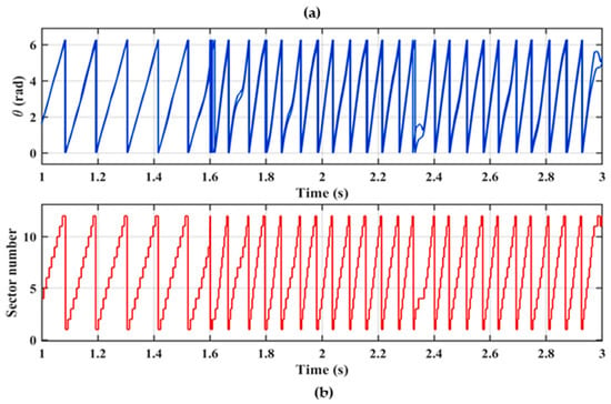
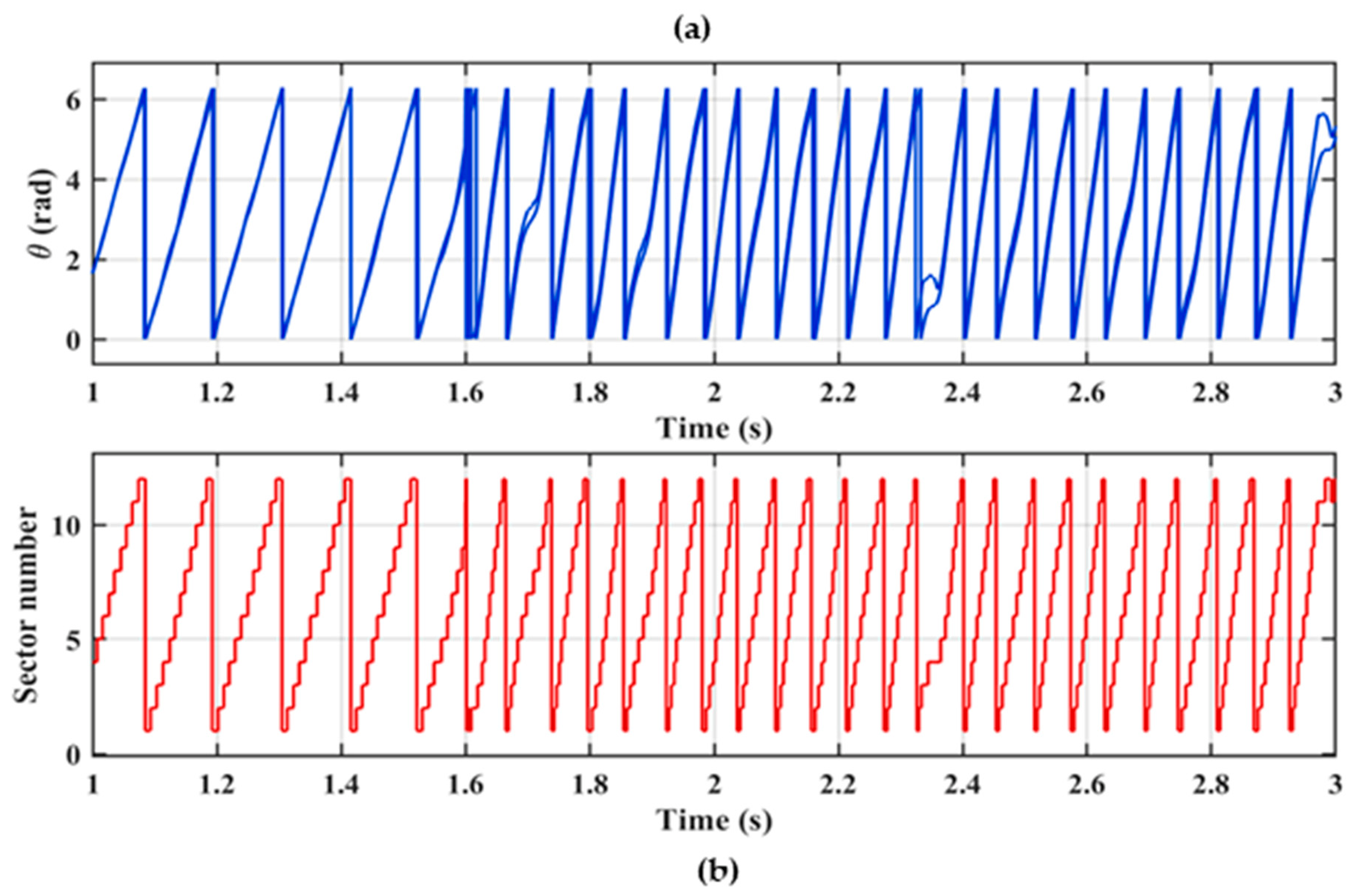
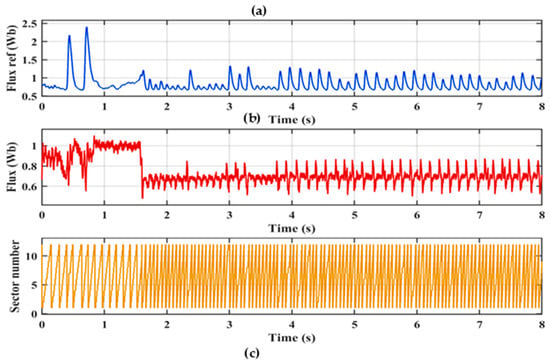
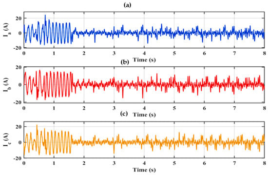
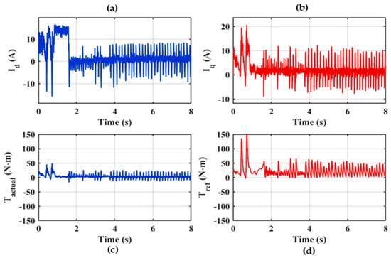
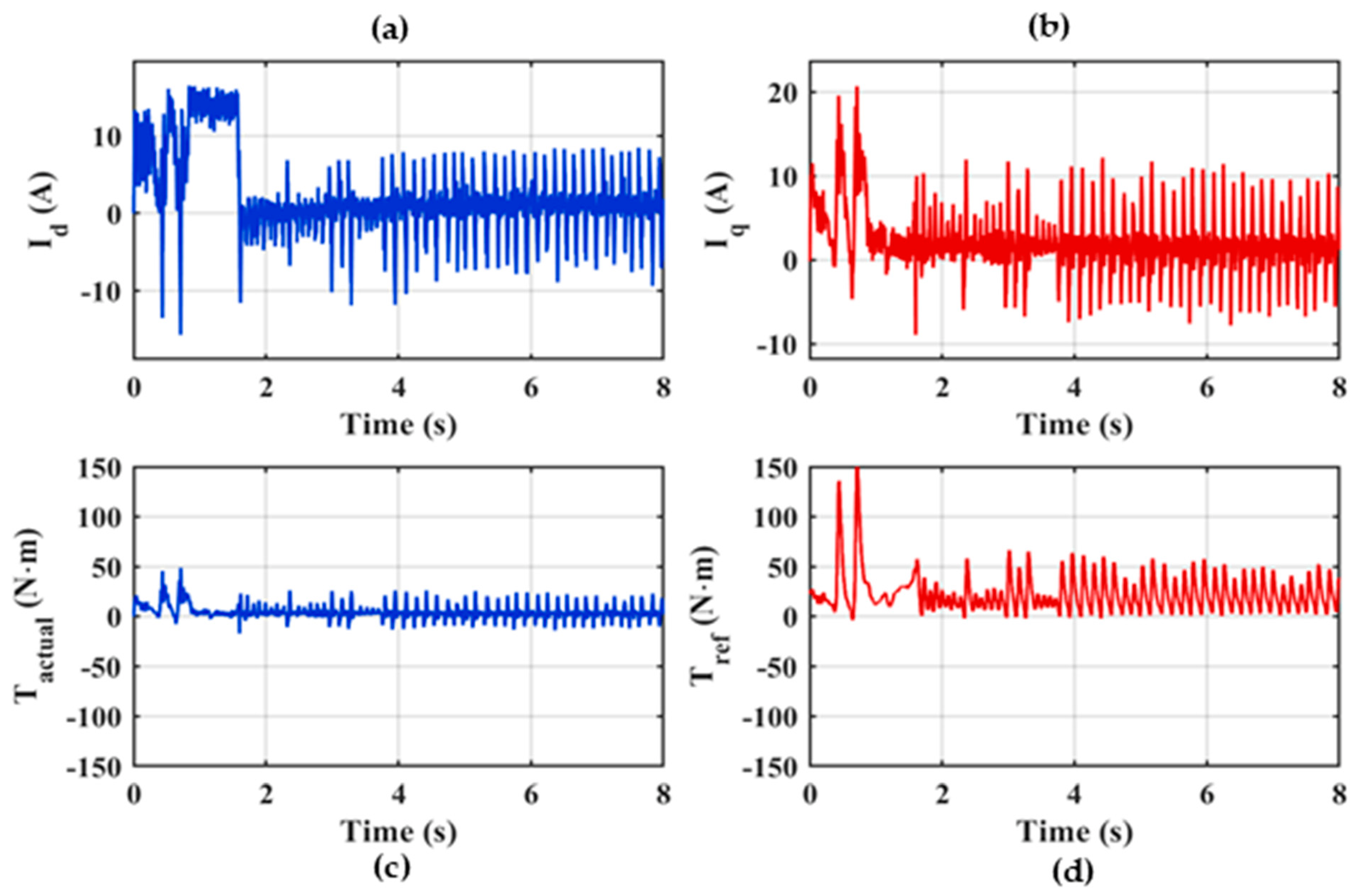
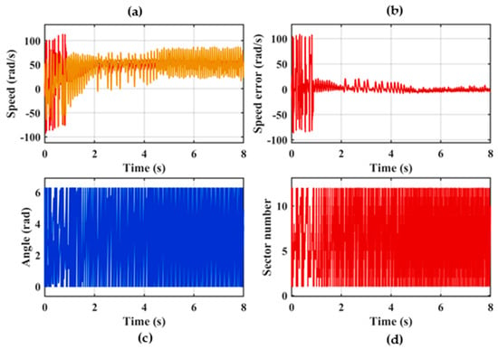
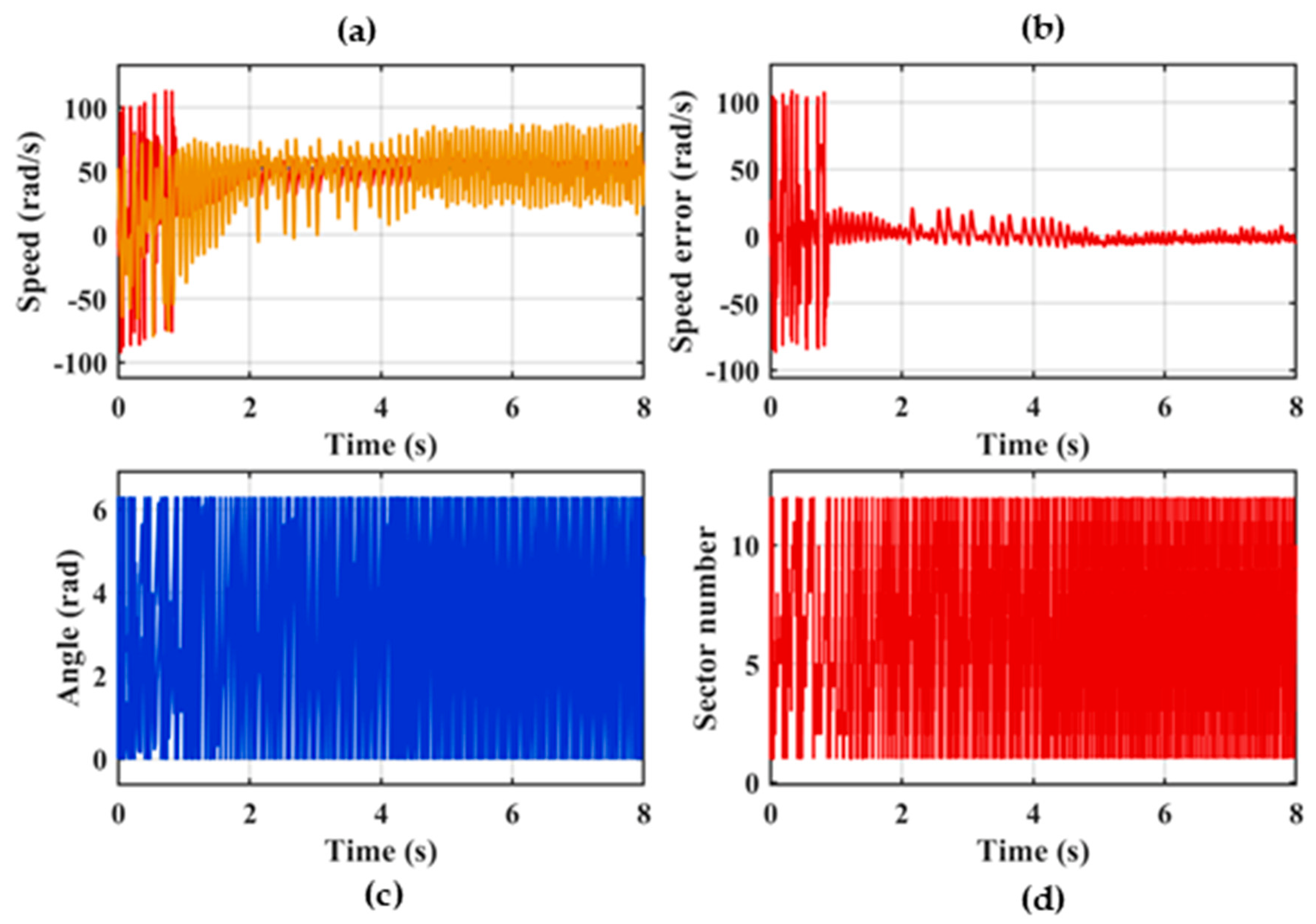
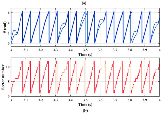
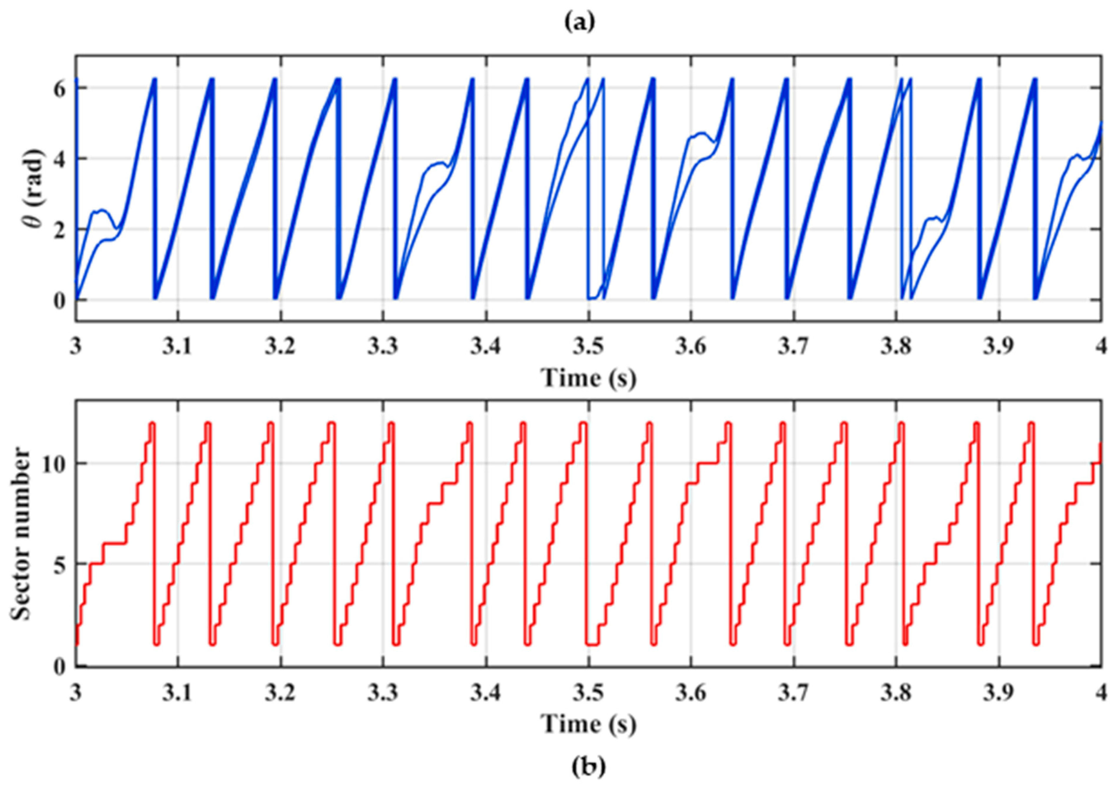
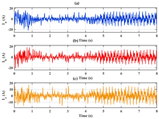
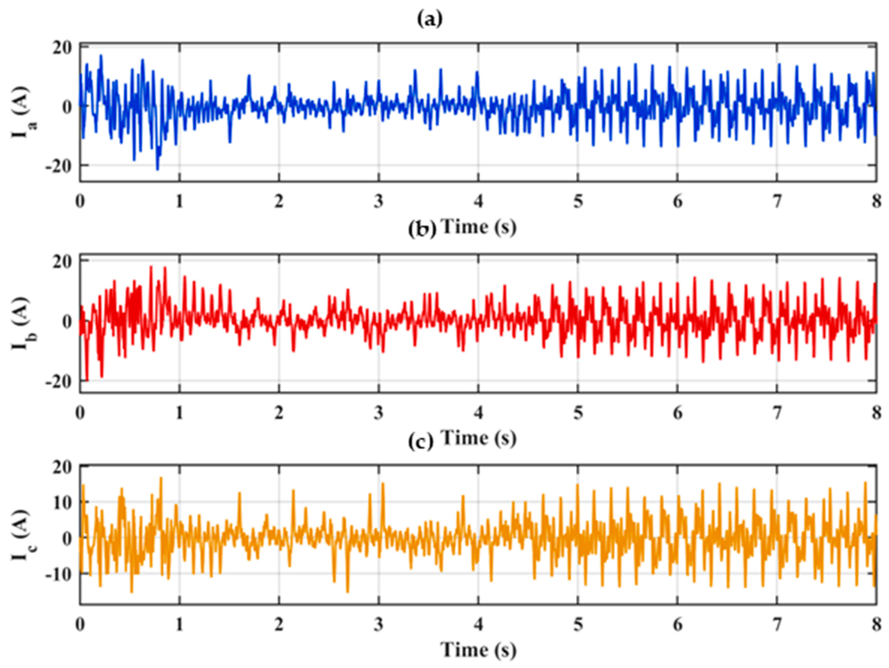
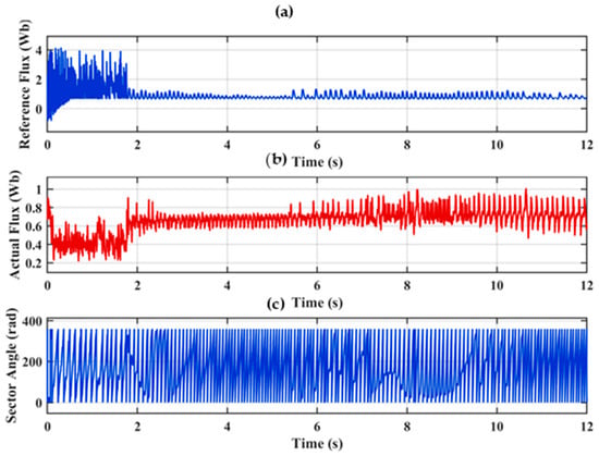
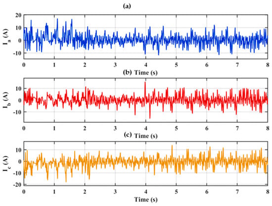
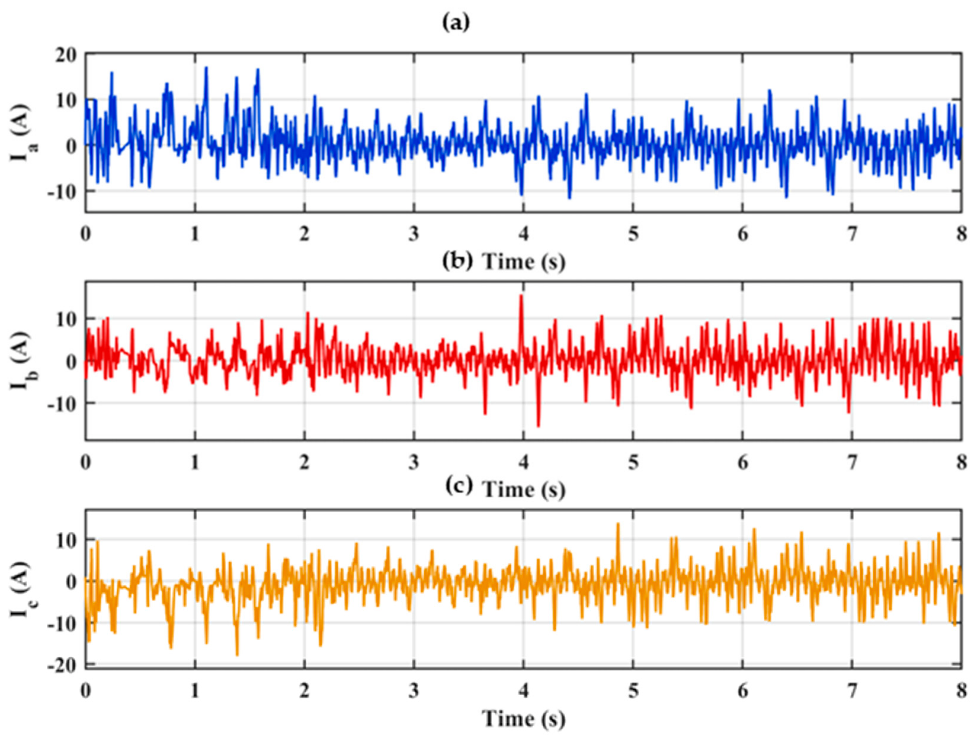
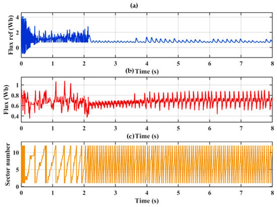
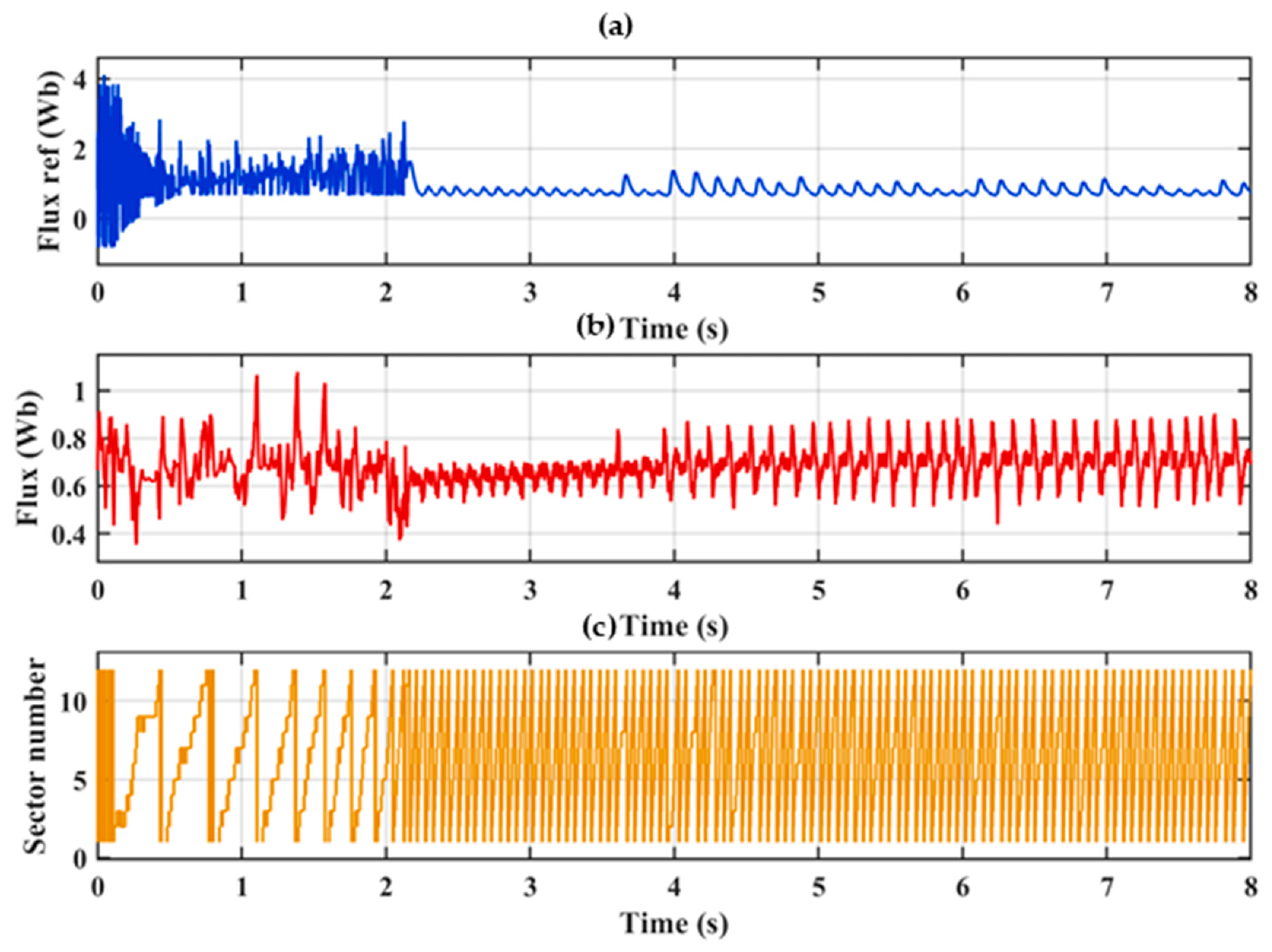
In the first case, the drive is commanded to a low reference speed, where the high-frequency injection observer is the active estimator. The estimated speed tracks the reference with a small steady-state error as shown in Figure 9a–d, and the estimated rotor position closely follows the actual position, confirming that the saliency-based observer provides accurate angle information in the region where the back-EMF is too weak for the MRAC estimator, as shown in Figure 10a,b. The reference and actual stator flux (Φref, Φactual) remain closely regulated, with the flux settling around its nominal value once the estimator transitions to steady-state operation, and the sector variation confirms smooth and continuous progression through all voltage-vector sectors as reflected in Figure 11a–c. The three-phase stator currents (Ia, Ib, Ic), as shown in Figure 12a–c, remain sinusoidal during the low-speed injection-based region, with the superimposed high-frequency component becoming more prominent as the drive speed increases, consistent with the increasing signal amplitude required to maintain reliable saliency tracking. The d–q axis currents (Id, Iq) remain within acceptable bounds, and the electromagnetic torque (Tactual), as shown in Figure 13a–d, follows the reference torque (Tref) with the expected ripple.
Figure 9.
Speed tracking performance: (a) reference(blue), estimated(brown), and actual speed response(red); (b) speed estimation error; (c) estimated rotor angle (θ) tracking; (d) sector variation.
Figure 10.
Zoomed view of angle and sector tracking (3–4 s): (a) rotor angle tracking; (b) sector variation.
Figure 11.
Stator flux and sector response: (a) reference flux; (b) actual flux; (c) sector variation.
Figure 12.
Three-phase stator-current response: (a) phase-a current Ia; (b) phase-b current Ib; (c) phase-c current Ic.
Figure 13.
Torque and dq-axis current response of the three-level inverter drive under constant load-torque condition: (a) Id; (b) Iq; (c) Tactual; (d) Tref.
7.2. Load-Torque Reversal at Constant Speed
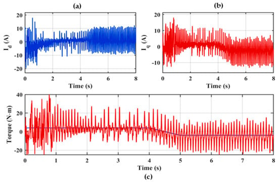
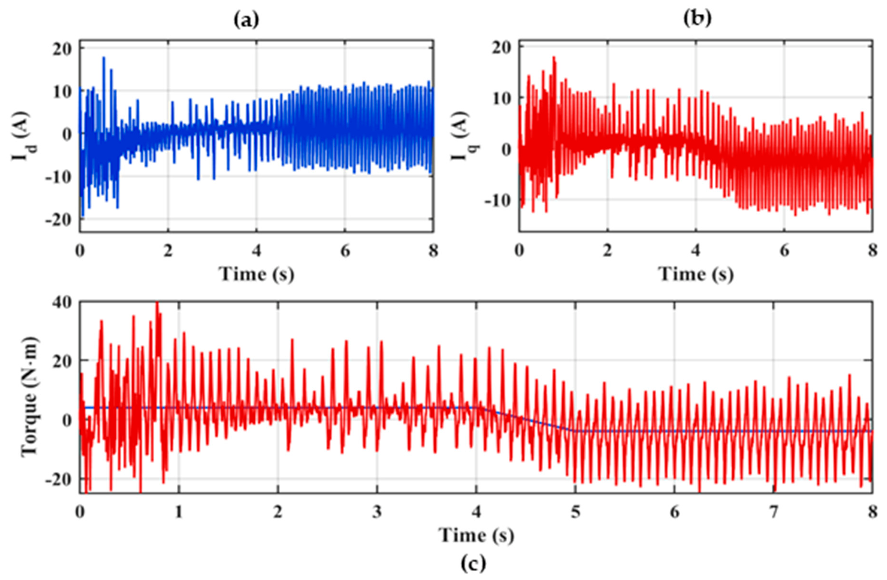
In the second case, the speed reference is held constant while the load torque is reversed. The d–q axis currents (Id, Iq) respond promptly to the reversed load demand, and the electromagnetic torque (Tactual) tracks the reversed reference torque (Tref) with only a brief transient before settling to the new operating condition, as shown in Figure 14a–c. The estimated speed remains locked to the reference throughout the reversal, with only a brief transient deviation, and the rotor position estimate remains clean throughout the transient, as shown in Figure 15a–d, as further confirmed by the zoomed view around the reversal instant, where the angle tracking and sector variation continue their smooth, continuous progression without discontinuity as represented by Figure 16a,b. The three-phase stator currents (Ia, Ib, Ic) reflect the reversed torque demand while remaining balanced throughout the transition, as shown in Figure 17a–c. The observed torque ripple is consistent with that reported for comparable three-level DTC drives and is presented without additional filtering, confirming that the sensorless drive rejects load disturbances without compromising estimation accuracy.
Figure 14.
Torque and dq-axis current response: (a) d-axis current (Id), (b) q-axis current (Iq), (c) reference(blue) and actual electromagnetic torque(red).
Figure 15.
Speed tracking performance: (a) reference(blue), estimated(brown), and actual speed response(red); (b) speed estimation error; (c) estimated rotor angle (θ) tracking; (d) sector variation.
Figure 16.
Zoomed view of angle and sector tracking (3–4 s): (a) rotor angle tracking; (b) sector variation.
Figure 17.
Three-phase stator-current response: (a) phase-a current Ia; (b) phase-b current Ib; (c) phase-c current Ic.
7.3. Dynamic-Speed Sensorless Operation
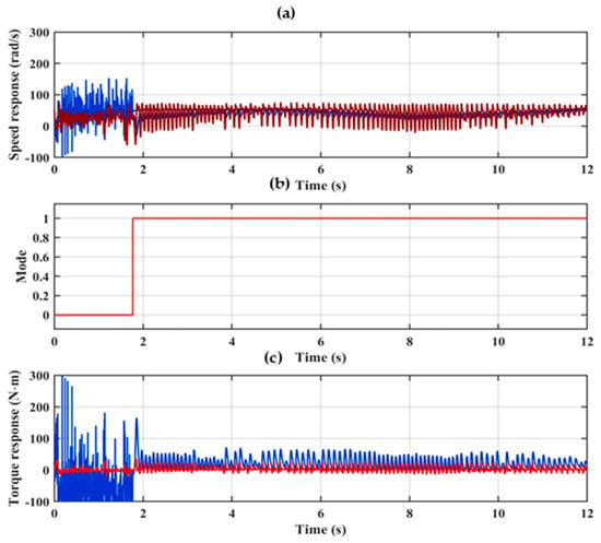
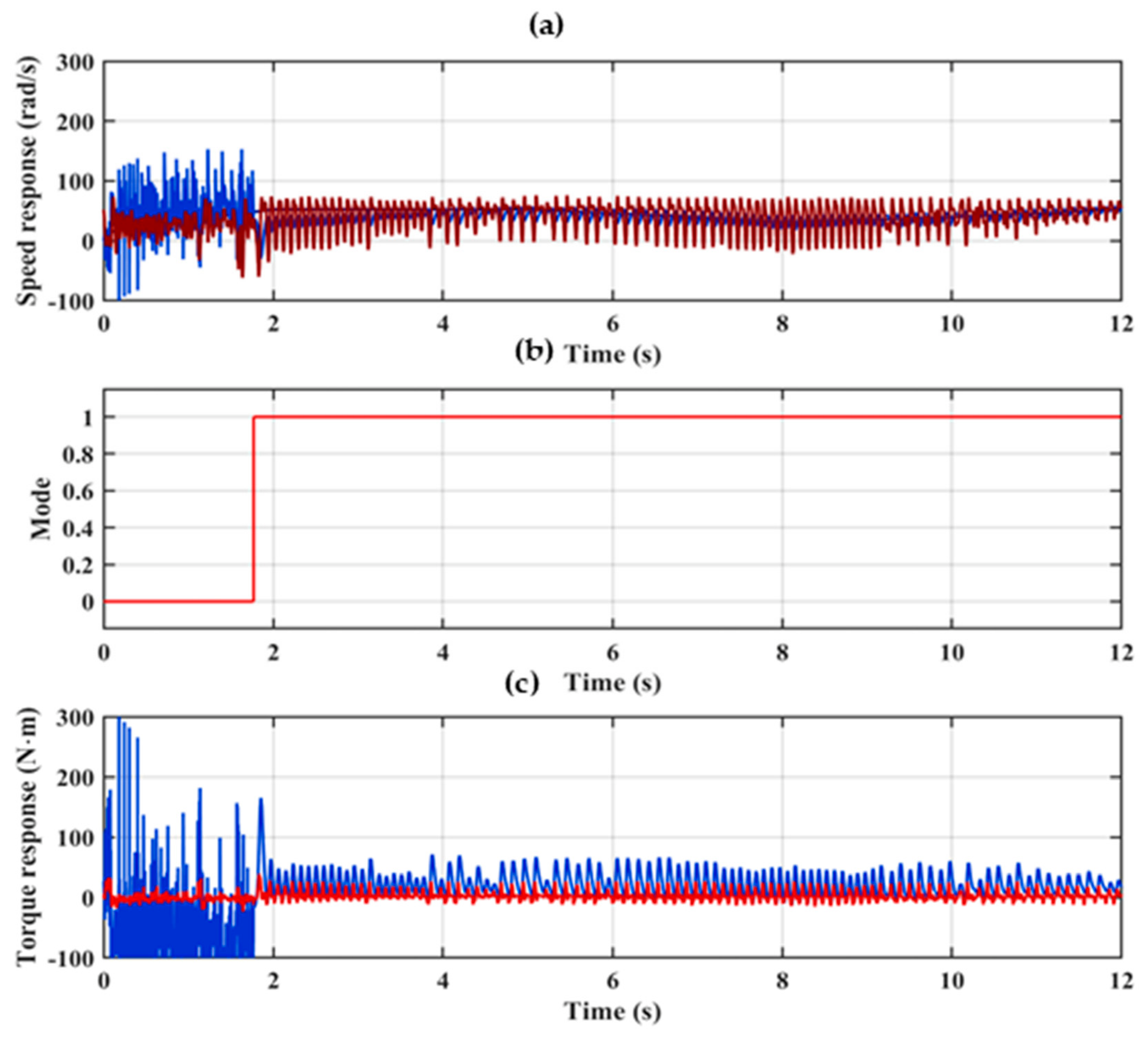
The performance of the drive under a dynamic speed command is examined next, in which the reference is initiated in the low-speed region and subsequently ramped to a higher value, thereby exercising both estimators within a single run. At start-up, the drive operates at low speed, where the back-EMF is too weak for the MRAC estimator, and the high-frequency injection observer therefore serves as the active estimator, with the mode signal held at logic ‘0’. As the reference rises beyond the transition threshold, control authority is handed over to the MRAC estimator and the mode signal steps to logic ‘1’, as shown in Figure 18a,b. Throughout this operation, the estimated speed tracks the reference with only a small steady-state error, and no discontinuity or transient overshoot appears in the speed response at the transition instant, confirming that the debounced, hysteresis-based handover between the two estimators is seamless and bump-free. Correspondingly, the electromagnetic torque (Tactual) follows the reference torque (Tref) with a low and well-bounded ripple, as shown in Figure 18c, the ripple being effectively suppressed by the expanded voltage-vector set of the three-level inverter.
Figure 18.
Speed tracking performance: (a) reference (yellow), estimated (blue), and actual speed response (red). (b) Selection mode (c) reference (blue) and estimated torque (red).
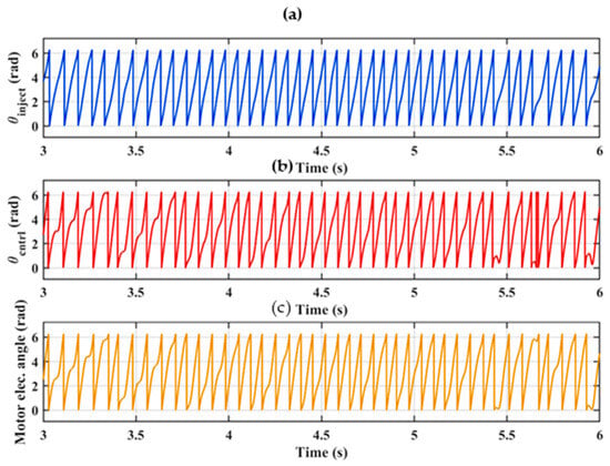
The stator flux is regulated accurately across the entire speed range. The reference and actual flux magnitudes (Φref, Φactual) remain closely matched and settle around the nominal value once the initial start-up transient subsides, as shown in Figure 19a,b, while the sector trajectory in Figure 19c advances smoothly and continuously through all voltage-vector sectors, indicating stable flux orientation before, during, and after the estimator handover. The accuracy of the position estimate underpins this behaviour: as shown in Figure 20a–c, the injection-based estimate (θ_inject), the current-model (MRAC) estimate (θ_ctrl), and the actual motor electrical angle remain closely aligned across the operating range, confirming that reliable angle information is maintained both in the low-speed injection region and in the higher-speed MRAC region.
Figure 19.
Reference and actual flux with sector response: (a) reference flux; (b) actual flux; (c) sector angle.
Figure 20.
Zoomed view of angle variation, 3–6 s: (a) theta inject; (b) theta control; (c) motor angle.
Finally, the three-phase stator currents (Ia, Ib, Ic), shown in Figure 21a–c respectively, remain balanced and sinusoidal throughout the transition. The superimposed high-frequency component is most pronounced in the low-speed injection region, where it is required to sustain reliable saliency tracking, and progressively diminishes as the drive accelerates and control authority passes to the MRAC estimator. The corresponding d–q axis currents (Id, Iq) remain within acceptable bounds at all times, confirming stable current regulation across the full speed range.
Figure 21.
Three-phase stator-current response: (a) Ia; (b) Ib; (c) Ic.
8. Processor-in-the-Loop Implementation
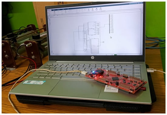
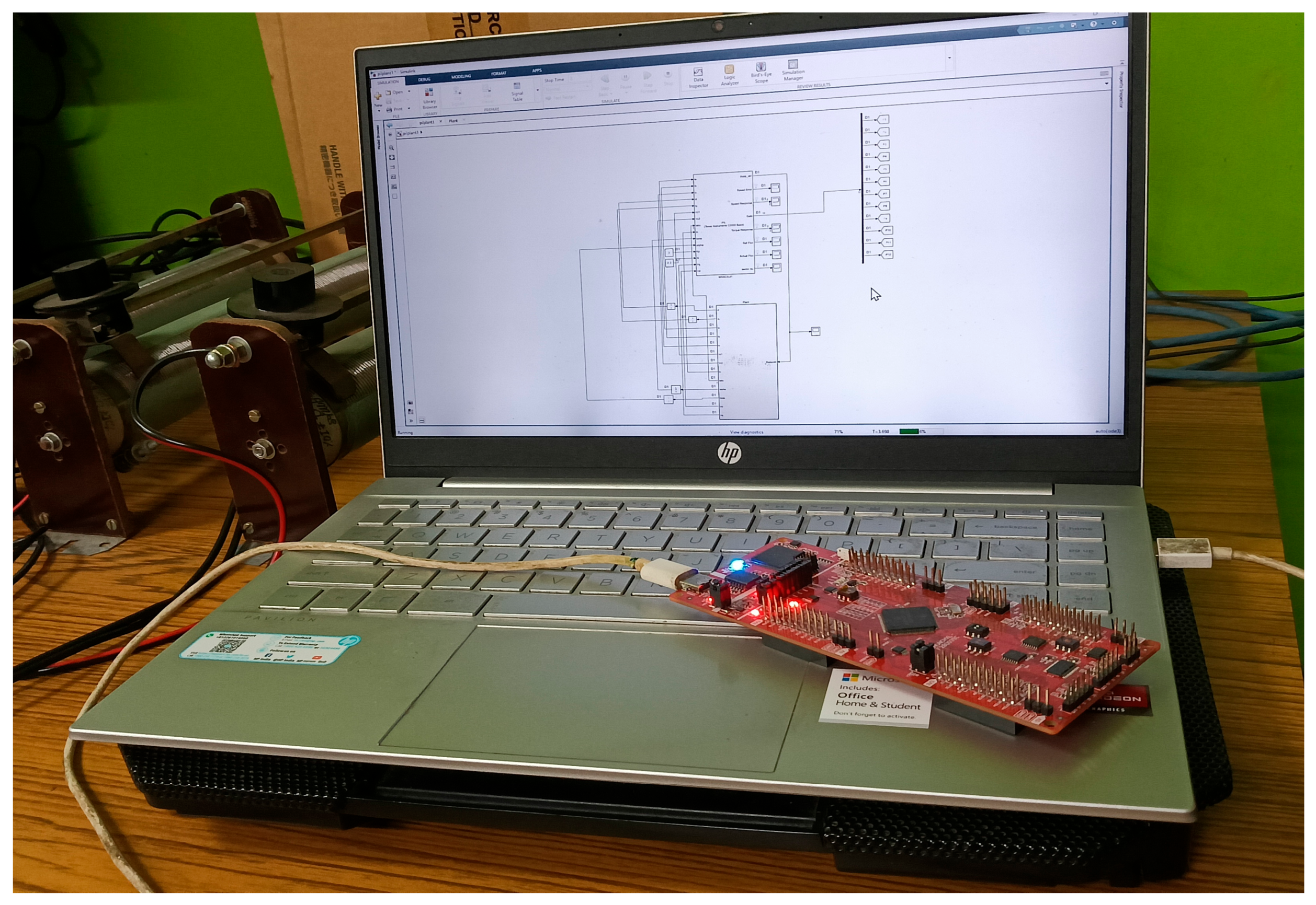
To establish that the proposed sensorless control algorithm is realizable on an embedded target and not merely in an idealized simulation environment, the complete controller was verified through processor-in-the-loop (PIL) co-simulation on a Texas Instruments TMS320F280039C digital signal controller, as shown in Figure 22. In the PIL configuration, the entire control algorithm, comprising the constant-switching-frequency DTC logic, the MRAC estimator, the high-frequency injection observer, the handover mechanism, and the MTPA reference generator, is compiled to target-native code and executed on the physical processor, while the IPMSM and three-level NPC inverter remain as a plant model on the host. At each control interval, the host exchanges the sensed plant quantities and the computed control commands with the target over the debug interface, ensuring that the algorithm runs on real hardware using single-precision arithmetic identical to that of a final deployment. The controller subsystem was configured for embedded code generation with an EABI toolchain and single-precision floating-point format consistent with the on-chip floating-point unit. A fixed control step of 50 μs was maintained across both the host plant solver and the target controller to preserve timing consistency between the two domains. All continuous-time elements of the controller were discretized prior to code generation, and the coordinate transformations were implemented so as to remove any algebraic loops that would otherwise obstruct real-time execution on the processor.
Figure 22.
PIL validation setup: host PC interfaced with the Texas Instruments LAUNCHXL-F280039C DSP.
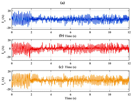
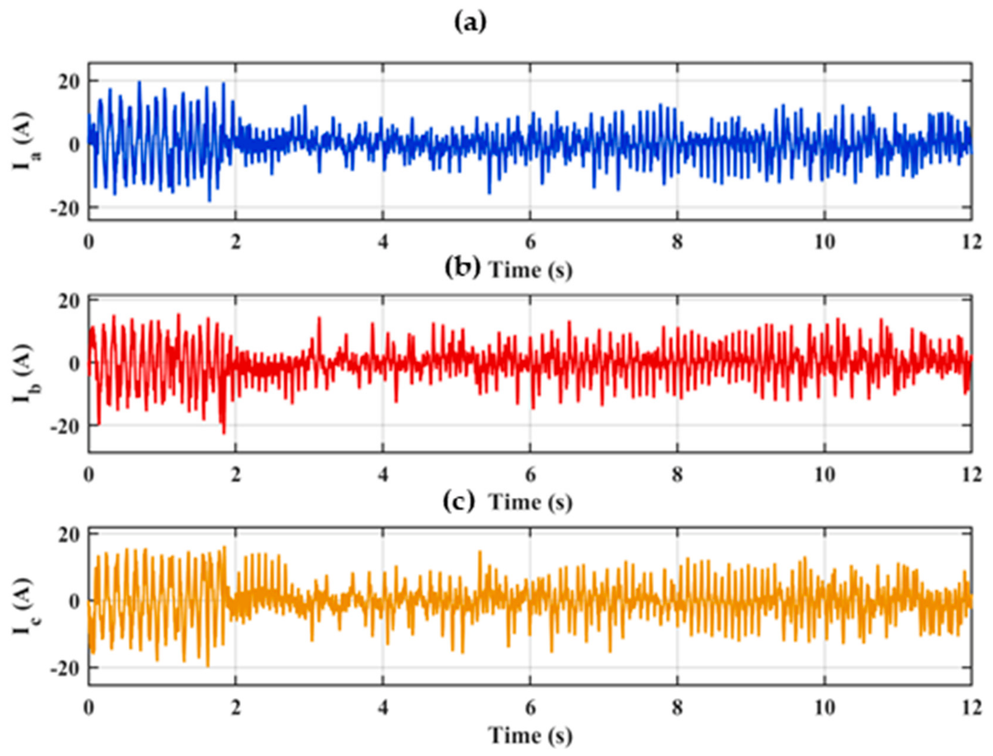
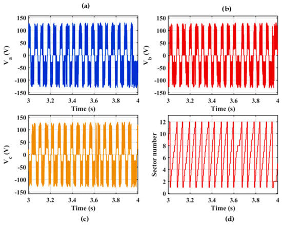
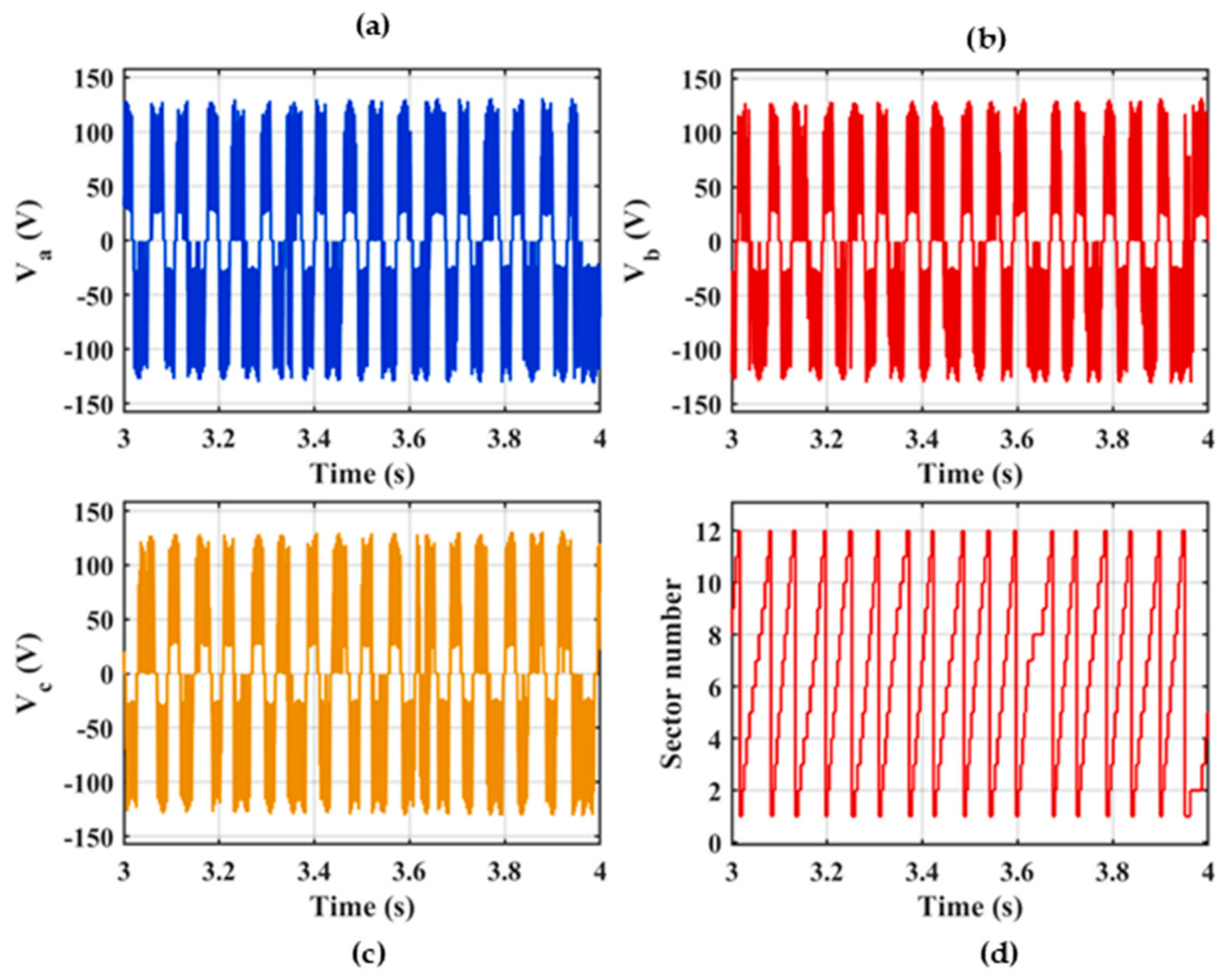
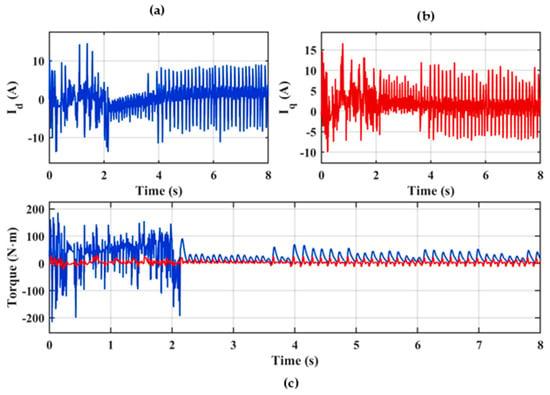
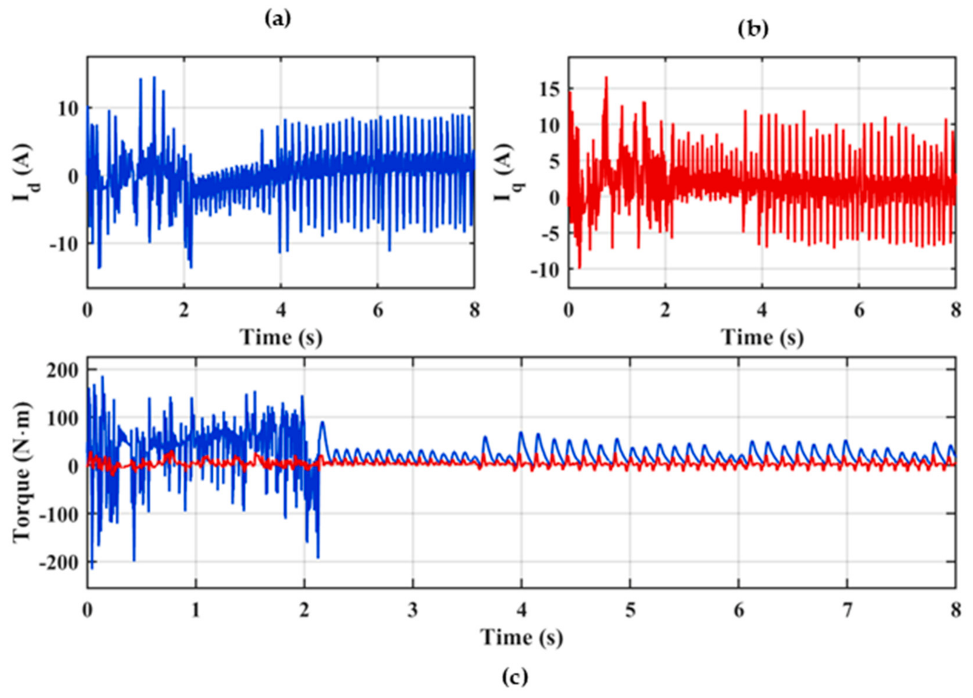
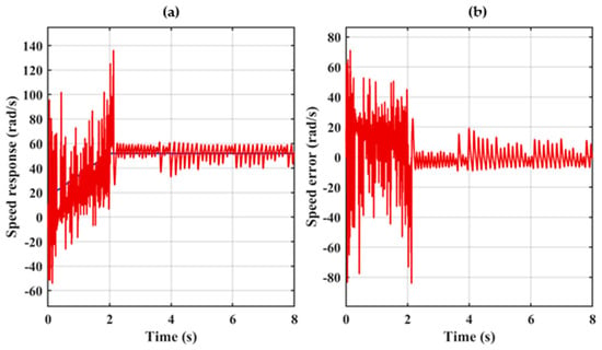
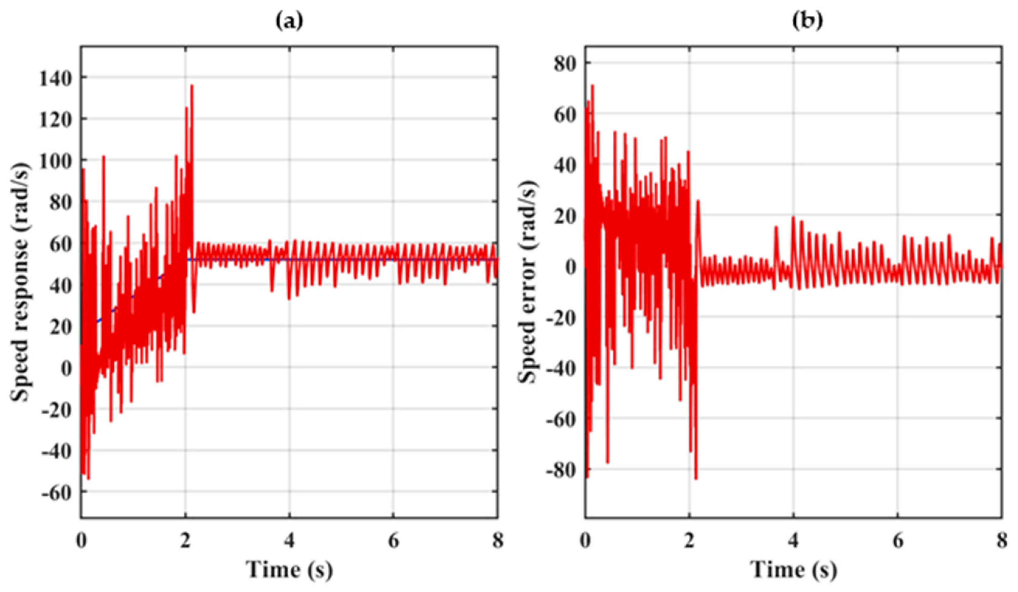
In this case, the drive is validated under processor-in-the-loop (PIL) execution on the target DSP. During the initial 0–2 s interval, the fixed-point/finite-precision arithmetic and real-time execution timing of the embedded platform introduce small deviations relative to the idealized double-precision offline simulation; because the injected signal and estimator states are inherently small in magnitude during this startup phase, these discretization effects are proportionally more pronounced. The zoomed phase-voltage waveforms (Va, Vb, Vc, 3–4 s) as reflected in Figure 23a–c and sector variation shown in Figure 23d further confirm the expected switching pattern, including the superimposed high-frequency injection component, thereby validating correct voltage-vector selection during real-time embedded execution and the d–q axis currents as shown in Figure 24a,b and torque response Figure 24c reflect this transient. The three-phase stator currents (Ia, Ib, Ic) shown in Figure 25a–c mirror this behaviour, while the reference and actual flux with sector variation Figure 26a–c confirm a rapidly continuous, uninterrupted progression through all voltage-vector sectors. Beyond t ≈ 2 s, once the estimator states and signal magnitudes grow sufficiently large, the influence of finite-precision execution becomes negligible, and the currents, torque, and speed response converge closely to the offline-simulated behaviour, with the speed error reducing to a small residual band Figure 27a,b. About System parameters, please see Table 2.
Figure 23.
Zoomed view of phase voltages and sector variation, 3–5 s: (a) Va, (b) Vb, (c) Vc, and (d) sector no.
Figure 24.
Torque and dq-axis current response: (a) Id, (b) Iq, and (c) torque reference (blue) and actual torque (red).
Figure 25.
Three-phase stator-current response: (a) Ia; (b) Ib; (c) Ic.
Figure 26.
Reference and actual flux with sector response: (a) reference flux; (b) actual flux; (c) sector no.
Figure 27.
Speed and speed-error response: (a) speed response; (b) speed error.
Table 2.
System parameters.
9. Conclusions
This paper has presented a hybrid flux-frame high-frequency (HF) injection and model reference adaptive control (MRAC)-based sensorless rotor position and speed estimation scheme for a three-level inverter-fed, direct-torque-controlled interior permanent magnet synchronous motor (IPMSM) drive. In contrast to conventional stationary-frame injection techniques, the proposed method demodulates the injected HF current directly in the stator-flux reference frame, thereby improving estimation fidelity at zero and low speed. A speed-dependent gating mechanism further governs the transition to the MRAC-based estimator as speed increases, mitigating the discontinuous angle transitions commonly associated with hard-switched hybrid observers. The proposed control scheme, incorporating a constant-switching-frequency torque regulator, was validated on a Texas Instruments LAUNCHXL-F280039C DSP through processor-in-the-loop (PIL) testing. The results confirm successful estimator startup from standstill and a smooth transition into the MRAC-based estimation region, with the proposed hybrid transition mechanism containing the ripple largely within the low-speed startup interval, beyond which the drive settles into stable, low-ripple operation. Implementation on this low-cost, single-core embedded platform, rather than on higher-end dual-core DSPs commonly used in sensorless drive research, underscores the practical viability of the proposed approach for cost-sensitive industrial motor drive applications.
Supplementary Materials
The following supporting information can be downloaded at https://www.mdpi.com/article/10.3390/machines14101153/s1, Table S1: Voltage Vector Switching Logic for a VSC-fed Drive; Table S2: Switching Table for 3L NPC Inverter.
Author Contributions
Conceptualization, A.C.; methodology, A.C.; software, A.C.; validation, A.C.; formal analysis, A.C.; investigation, A.C.; data curation, A.C.; writing—original draft preparation, A.C.; writing—review and editing, P.S.B. and A.K.S.; visualization, A.C.; supervision, P.S.B. and A.K.S. All authors have read and agreed to the published version of the manuscript.
Funding
This research received no external funding.
Data Availability Statement
Data are contained within the article. The original contributions presented in this study are included in the article/supplementary material. Further inquiries can be directed to the corresponding authors.
Acknowledgments
I would like to express my sincere appreciation to my research supervisor, Partha Sarathee Bhowmik, Department of Electrical Engineering, NIT Durgapur, for his insightful guidance and continuous support throughout this work. I am grateful to A.K. Saha, Academic Leader (Research and Higher Degrees), School of Engineering, University of KwaZulu-Natal, for his constructive input and acknowledge partial instrument facility support from a project funded by the SERB, DST, Govt. of India, under the funding scheme (sanction order no. EEQ/2016/000347; dated: 24 April 2017.
Conflicts of Interest
The authors declare no conflicts of interest.
References
- Ren, Y.; Zhu, Z.Q.; Liu, J. Direct torque control of permanent-magnet synchronous machine drives with a simple duty ratio regulator. IEEE Trans. Ind. Electron. 2014, 61, 5249–5258. [Google Scholar] [CrossRef] [Scilit]
- Mohan, D.; Zhang, X.; Foo, G.H.B. Direct torque control of IPMSM driven by a three-level NPC inverter with torque and capacitor voltage ripple reduction. In Proceedings of the 2015 IEEE Applied Power Electronics Conference and Exposition (APEC), Charlotte, NC, USA, 15–19 March 2015; pp. 557–564. [Google Scholar] [CrossRef] [Scilit]
- Niu, F.; Li, K.; Wang, Y. Direct torque control for permanent-magnet synchronous machines based on duty ratio modulation. IEEE Trans. Ind. Electron. 2015, 62, 6160–6170. [Google Scholar] [CrossRef] [Scilit]
- Mohan, D.; Zhang, X.; Foo, G.H.B. Three-Level Inverter-Fed Direct Torque Control of IPMSM With Constant Switching Frequency and Torque Ripple Reduction. IEEE Trans. Ind. Electron. 2016, 63, 7908–7918. [Google Scholar] [CrossRef] [Scilit]
- Shinohara, A.; Inoue, Y.; Morimoto, S.; Sanada, M. Direct Calculation Method of Reference Flux Linkage for Maximum Torque per Ampere Control in DTC-Based IPMSM Drives. IEEE Trans. Power Electron. 2017, 32, 2114–2122. [Google Scholar] [CrossRef] [Scilit]
- Mohan, D.; Zhang, X.; Foo, G.H.B. A simple duty cycle control strategy to reduce torque ripples and improve low-speed performance of a three-level inverter-fed direct torque controlled interior permanent magnet synchronous motor drive. IEEE Trans. Ind. Electron. 2017, 64, 2709–2721. [Google Scholar] [CrossRef] [Scilit]
- Wu, B.; Narimani, M. High-Power Converters and AC Drives, 2nd ed.; IEEE Press: Piscataway, NJ, USA; John Wiley & Sons: Hoboken, NJ, USA, 2017. [Google Scholar]
- Naganathan, P.; Srinivas, S. Maximum Torque Per Ampere Based Direct Torque Control Scheme of IM Drive for Electrical Vehicle Applications. In Proceedings of the IEEE 18th International Power Electronics and Motion Control Conference (PEMC), Budapest, Hungary; IEEE: Piscataway, NJ, USA, 2018; pp. 256–261. [Google Scholar] [CrossRef] [Scilit]
- Wei, F.; Wang, Y.; Liang, Q.; Li, Z. Sensorless Control of Permanent Magnet Synchronous Motor Based on Improved Model Reference Adaptive System. In Proceedings of the Chinese Automation Congress (CAC), Hangzhou, China; IEEE: Piscataway, NJ, USA, 2019; pp. 2422–2426. [Google Scholar] [CrossRef] [Scilit]
- Sharma, T.; Bhattacharya, A. Performance Analysis of Encoderless DTC of IPMSM for Wide Operating Range. Arab. J. Sci. Eng. 2020, 45, 6501–6515. [Google Scholar] [CrossRef] [Scilit]
- Hakami, S.S.; Lee, K.-B. Four-Level Hysteresis-Based DTC for Torque Capability Improvement of IPMSM Fed by Three-Level NPC Inverter. Electronics 2020, 9, 1558. [Google Scholar] [CrossRef] [Scilit]
- Sharma, T.; Bhattacharya, A. Modified LUT-based DTC of NPC 3-Level Inverter-fed Sensorless IPMSM Drive with DC Link Voltage Balance. IETE Tech. Rev. 2022, 39, 157–178. [Google Scholar] [CrossRef] [Scilit]
- Sun, X.; Zhang, Y.; Tian, X.; Cao, J.; Zhu, J. Speed Sensorless Control for IPMSMs Using a Modified MRAS With Gray Wolf Optimization Algorithm. IEEE Trans. Transp. Electrif. 2022, 8, 1326–1337. [Google Scholar] [CrossRef] [Scilit]
- Nasr, A.; Gu, C.; Wang, X.; Buticchi, G.; Bozhko, S.; Gerada, C. Torque-Performance Improvement for Direct Torque-Controlled PMSM Drives Based on Duty-Ratio Regulation. IEEE Trans. Power Electron. 2022, 37, 749–760. [Google Scholar] [CrossRef] [Scilit]
- Li, Y.; Hu, H.; Shi, P. A Review of Position Sensorless Compound Control for PMSM Drives. World Electr. Veh. J. 2023, 14, 34. [Google Scholar] [CrossRef] [Scilit]
- Elkholy, M.M.; Algendy, M.M.; El-Hay, E.A. Modern Control Techniques and Operational Challenges in Permanent Magnet Synchronous Motors: A Comprehensive Review. Automation 2025, 6, 49. [Google Scholar] [CrossRef] [Scilit]
- Jnayah, S.; Ben Mahmoud, Z.; Guenenna, T.; Khedher, A. An Improved DTC Scheme Based on Common-Mode Voltage Reduction for Three Level NPC Inverter in Induction Motor Drive Applications. Automation 2026, 7, 33. [Google Scholar] [CrossRef] [Scilit]
- Krishnan, R. Electric Motor Drives: Modeling, Analysis and Control; Pearson Education: Upper Saddle River, NJ, USA, 2001. [Google Scholar]
- Bose, B.K. Power Electronics and Variable Frequency Drives: Technology and Applications; IEEE Press: Piscataway, NJ, USA; John Wiley & Sons: New York, NY, USA, 1997. [Google Scholar]
- Wang, G.; Valla, M.; Solsona, J. Position Sensorless Permanent Magnet Synchronous Machine Drives—A Review. IEEE Trans. Ind. Electron. 2020, 67, 5830–5842. [Google Scholar] [CrossRef] [Scilit]
- Kumar, S.; Singh, B. Improved MRAC Based Sensorless PMSM Drive with Enhanced Speed Control for LEV Application. IEEE Trans. Energy Convers. 2025, 40, 1153–1164. [Google Scholar] [CrossRef] [Scilit]
- Wang, Z.; Yu, K.; Li, Y.; Gu, M. Position Sensorless Control of Dual Three-Phase IPMSM Drives with High-Frequency Square-Wave Voltage Injection. IEEE Trans. Ind. Electron. 2023, 70, 9925–9934. [Google Scholar] [CrossRef] [Scilit]

Disclaimer/Publisher’s Note: The statements, opinions and data contained in all publications are solely those of the individual author(s) and contributor(s) and not of MDPI and/or the editor(s). MDPI and/or the editor(s) disclaim responsibility for any injury to people or property resulting from any ideas, methods, instructions or products referred to in the content. |
© 2026 by the authors. Licensee MDPI, Basel, Switzerland. This article is an open access article distributed under the terms and conditions of the Creative Commons Attribution (CC BY) license.