


Taikobot: A Full-Size and Free-Flying Humanoid Robot for Intravehicular Astronaut Assistance and Spacecraft Housekeeping

1
College of Aerospace Science and Engineering, National University of Defense Technology, Changsha 410073, China
2
College of Control Science and Engineering, Zhejiang University, Hangzhou 310000, China
3
Huzhou Institute of Zhejiang University, Huzhou 313000, China
*
Author to whom correspondence should be addressed.
Machines 2022, 10(10), 933; https://doi.org/10.3390/machines10100933
Submission received: 12 September 2022
/
Revised: 29 September 2022
/
Accepted: 10 October 2022
/
Published: 13 October 2022
(This article belongs to the Topic Intelligent Systems and Robotics)
Abstract
:This paper proposes a full-size and free-flying humanoid robot named Taikobot that aims to assist astronauts in a space station and maintain spacecrafts between human visits. Taikobot adopts a compact and lightweight (∼25 kg) design to work in microgravity, which also reduces launch costs and improves safety during human–robot collaboration. Taikobot’s anthropomorphic dual arm system and zero-g legs allow it to share a set of intravehicular human–machine interfaces. Unlike ground-walking robots, Taikobot maneuvers in a novel push–flight–park (PFP) strategy as an equivalent astronaut in a space station to maximize workspace and flexibility. We propose a PFP motion planning and control method based on centroidal dynamics and multi-contact model. Based on the proposed method, we carried out extensive simulations and verified the feasibility and advantages of the novel locomotion strategy. We also developed a prototype of Taikobot and carried out several ground experiments on typical scenarios where the robot collaborates with human astronauts. The experiments show that Taikobot can do some simple and repetitive tasks along with astronauts and has the potential to help astronauts improve their onboard working efficiency.
1. Introduction
Space habitats such as a low-Earth orbit space station have been providing long-term platforms for human beings to conduct scientific research. The operation and maintenance of a space station is a complex task where astronauts have been playing a significant role. However, due to the launch cost and risk, human resources in space are scarce and expensive. In the future, astronauts will become increasingly physically and cognitively challenged as missions become longer and more varied [1]. Although many onboard operations still need to be conducted by astronauts who are skilled at reasoning and resolving system uncertainties, robots are being used as assistants and even replicants more and more frequently to reduce the workload of astronauts.
Compared with human astronauts that require a complex array of machinery to live in space, robotic assistants are capable of working 24/7 and consume only solar energy. Moreover, future human habitats in deep space such as a space station in lunar orbit [2] may not adapt to the long-term presence of human beings due to the cosmic radiation and their distance from the Earth [3]. Robots can be used as housekeepers of these habitats and conduct basic operations and maintenance when crew members are absent. Space tourism is one of the most potential areas for the development of space economy [4]. Shortly, robots could even serve mass space tourists. With the prosperity of manned space activities such as space tourism and deep space exploration, robots are set to become our partners in space and extend our strength and ability beyond our Earth cradle.
Up to now, several in-cabin robots of various types and functionalities have been developed to assist astronauts and improve their onboard working efficiency [5,6,7,8,9,10,11]. Int-Ball [6] is a spherical camera drone that can record high-definition videos under remote control, currently deployed in the Japanese Experiment Module. It aims to realize zero photographing time by onboard crew members which amounts to about 10% of their working hours. Astrobee [7], which has been built on the lessons learned from PSA (Personal Satellite Assistant) [8] and SPHERES (Synchronized Position Hold, Engage, Reorient, Experimental Satellite) [9], is a free-flying multi-robot system mainly consisting of three cube-shaped robots propelled by electric fans to work alongside astronauts onboard the ISS. Each square robot of Astrobee carries a micro perching arm that allows them to grab handrails to save energy and move cargoes throughout the space station [10]. Astrobee and Int-Ball are both designed with the concept of a flying drone in microgravity with a similar size to a football and are capable of accomplishing some simple tasks.
Compared with the spherical Int-Ball and square Astrobee, an anthropomorphic structure endows a robot with more flexibility, dexterity, and strength, and can accomplish a richer set of tasks. Robonaut 2 is a humanoid robot currently developed by NASA that aims to work side by side with human astronauts and carry out operations where the risks are too great for people [12,13]. Initially deployed as a torso-only humanoid restricted to a stanchion, the robot is now augmented with two climbing legs with grippers, allowing it to maneuver between handrails. Robonaut 2 weighs about 220 kg and is still under test onboard the ISS [14]. Skybot F-850 is a dexterous humanoid robot developed by Russia. It is 1.8 m tall and weighs over 100 kg [15]. It is also designed to work in place of human astronauts. In August 2019, Skybot F-850 completed a 2-week test onboard the ISS.
Humanoid robots of such types are more like general-purpose service robots. They can even accomplish a variety of tasks on planet surfaces where they must overcome gravity. For example, Valkyrie [16], a new generation of humanoid robot developed by NASA, can undertake some post-disaster rescue work on Earth. The Skybot F-850 can even drive a car. However, to overcome gravity, these robots are equipped with strong joints and supporting structures, which increases their mass budget. When working in microgravity, a lightweight design can be adopted to reduce the launch cost and improve proximity safety [17,18] during human–robot collaboration.
As shown in Figure 1, inspired by the concept of a 3D printed torso-only robot, InMoov [19], we designed a full-size and lightweight humanoid robot, Taikobot, whose name originates from Taikonaut. We have carried out extensive research and test in terms of its locomotion strategy in microgravity and means of human–robot collaboration [20] that closely relate to its onboard deployment. As a full-size humanoid, Taikobot weighs only 25 kg due to the extensive use of 3D print technology and lightweight joints. Taikobot is not only designed with a human shape and size, but also aims to perform like a real astronaut. With dual arm system and dexterous hands, the robot is able to handle the same tools and interfaces that crew members use. With human-like limbs, Taikobot is designed to traverse through the space station in a PFP locomotion strategy resembling what human astronauts do in microgravity, and this enables it to move freely and timely in a wide range with limited constraints.
The rest of this paper is organized as follows. In Section 2, the system overview and mechatronic design of Taikobot are introduced. In Section 3, we focus on algorithms that resolve the motion planning and control problem of the PFP locomotion strategy in microgravity. Experiments that evaluate the overall design and related algorithms are discussed in Section 4. Finally, we summarize in Section 5.
2. System Overview and Mechatronic Design
Taikobot is essentially a humanoid robotic assistant operating in a zero-gravity environment such as a low-Earth orbit space station.
As shown in Figure 2, Taikobot’s design has referred to human ergonomics to a large extent to facilitate human–robot collaboration. Taikobot is 1.71 m tall. It consists of an anthropomorphic dual arm system with 6 DOFs each, two dexterous hands with 15 DOFs each, a torso with 2 DOFs, two zero-g legs with 4 DOFs each, plus a pan-tilt unit in the head to facilitate environmental awareness. In total, Taikobot has 54 DOFs to provide enough whole-body flexibility in a space station. Taikobot mainly performs the following three typical intravehicular tasks:
- Autonomous inspection and search in the space station.
- Astronaut accompanying and work assistance.
- Basic operations and maintenance of the space station between human visits.
Autonomous inspection and search are the most basic tasks where Taikobot patrols in a space station doing inspection, taking inventory, and making documentation mainly with its onboard sensors such as RGB-D camera, thermometer, and RFID (Radio Frequency Identification) reader. Astronaut accompanying and work assistance are the major work of Taikobot where it follows a crew member and provides immediate services such as photographing, tool delivery, and cooperative operations. When crew members are absent, Taikobot is expected to work alone and become a caretaker for the spacecraft.
Benefiting from the special microgravity environment, it does not require any bulky structure and powerful joints to support and drive the robot. Large electric motors and high reduction ratio machinery commonly used in ground robots [21,22] can be avoided, and lightweight 3D printed structures with fiber-reinforced nylon and joints sufficient for zero-g locomotion and operations are widely adopted in the design, which gives the robot a gross weight of merely 25 kg. The lightweight design also benefits proximity safety and reduces launch costs.
2.1. Mechanical Design
- (1)
- Human-Like Dual Arm System
Taikobot’s dual arm system is designed to perform bimanual manipulation and help implement in-cabin locomotion in microgravity. As shown in Figure 2b, the first three joints in the shoulder are in roll–pitch–yaw configuration, with a kinematic disposition and range of motion like a human arm. The remaining three joints in the elbow and wrist are in pitch–yaw–pitch configuration. The 6-DOF arm enables the robot to manipulate objects in any pose in the dexterous workspace. More importantly, when Taikobot grasps and holds a handrail in a space station, it can adjust its pose more flexibly.
Taikobot is designed to have a relatively large arm span (1.92 m) to facilitate onboard operations. As shown in Figure 3, the workspace of a single arm is about 0.66 m from the shoulder to the center of the palm. The workspace of the dual arm system almost cover the entire space with few blind areas on the back. It is worth mentioning that the two additional joints in the waist can also enlarge the workspace of the dual arm system.
The transmission mechanism of the joints mainly includes miniaturized worm gears and multi-thread lead screws. Figure 4a gives the exploded view of joint C in the right shoulder. The motor shaft is connected to a miniaturized worm gear package with a reduction ratio of 15. Considering the transmission efficiency, the joint can provide a control torque of about 60 Nm. In terms of sensors, each joint unit includes both a relative and an absolute position encoder to achieve accurate and unconfused joint control. The arm weighs about 3 kg and has a payload of 2 kg in earth gravity.
- (2)
- End Effectors
The end effectors in the upper body of Taikobot are two cable-driven hands with five independent fingers, and each finger has 3 coupled DOFs actuated through one of the five micro-electric motors in the palm. The compact design helps minimize cable routing for quick response and makes the hand a fully independent module. Each finger includes both a tactile sensor that resides on top of the fingertip and a position sensor within the corresponding driving motor. These sensor inputs can provide important feedback when Taikobot makes physical interaction with its surroundings.
Figure 4b presents a detailed view of the hand design where torsional springs are installed in each knuckle for restoration. The trade-off between joint velocity and torque can be achieved by selecting pulleys with appropriate diameters. The micro-electric motor in the palm can produce a maximum torque of 0.2 Nm. The diameter of the pulley is designed to be 10 mm. Therefore, the theoretical maximum tension on the cable can be as large as 40 N. Considering friction force, restoration torque of the torsional spring, and the pose of the finger, the maximum contact force on the fingertip is measured at 15 N during ground experiments. Although designed simple and compact, the hand can grasp and manipulate a variety of objects on the ground.
Taikobot’s feet are designed to have large and flat contact surfaces so that a more stable interaction with the inner wall can be achieved. The length of the feet is also designed to be relatively large (∼25 cm). The center of pressure of the reaction forces can be actively controlled within the range of the feet by exerting different joint torques, which lays the basis for active angular momentum control during the PFP locomotion.
- (3)
- Zero-g Legs and Torso
Unlike ground-walking robots, Taikobot’s locomotion is mainly achieved by utilizing the reaction forces between its limbs and the inner walls with the PFP strategy. In the lower body, two zero-g legs (or legs for locomotion in zero-g environment) are designed to help Taikobot transverse and dock throughout the space station.
Considering the special task of the zero-g leg system, each leg is designed with 4 degrees of freedom, including 1 DOF for the hip, 1 DOF for the knee, and 2 DOFs for the ankle. Figure 3a shows the workspace of the leg system. A fully stretched leg is designed to be 0.95 m long. Motors are placed as close to the torso as possible to produce a slim leg with low inertia, which also reduces the disturbance to body due to the leg’s motion in microgravity. Extension and flexion of each leg are driven by the first two joints in the hip and knee, while the lateral and rotational motion of the legs can be adjusted by utilizing two additional waist joints. The integrated design of the waist and leg system has largely simplified the joint configuration in the lower body. Simulation results in Section 3 and Section 4 also show that this joint configuration can meet the basic needs of intravehicular locomotion. One typical docking strategy for Taikobot is to fix its feet into the foot restraints and establish a stable connection to the cabin. Therefore, more flexible ankles with 2 DOFs are designed to ease the docking process.
As shown in Figure 4c, each zero-g leg also adopts a musculoskeletal structure. The structure uses two lightweight carbon fiber rods as the supporting bones, and a triangular bar with a lead screw mechanism to drive the joint. The musculoskeletal design decouples the supporting structure and driving mechanism of the leg system and can provide more strength in highly dynamic scenarios.
To summarize, Taikobot is designed compact, lightweight, and dexterous with human-like dual arm system and customized zero-g legs for intravehicular locomotion and manipulation. The humanoid design also facilitates human–robot collaboration. The overall joint configuration of Taikobot is shown in Figure 2, and the joint specifications are listed in Table 1.
2.2. Sensors and Computing Architecture
The human can accomplish a wide variety of operations with only visual and tactile inputs. We also seek to use fewer sensory inputs for Taikobot to accomplish various onboard tasks. An RGB-D camera is mounted in the head for astronaut accompanying and intravehicular visual navigation. An inertial measurement unit is installed near the center of mass (COM) to provide measurement in 1 kHz. A microphone and micro speaker pair is mounted in the head for human–robot communication. In terms of force sensors, 6-DOF force/torque sensors are to be integrated just above each foot and hand to measure the reaction wrenches, providing necessary information for intravehicular motion planning and control. Tactile sensors are installed on top of each fingertip to assist handrail grasping and object manipulation.
Taikobot adopts a hierarchical computing and control architecture to enhance efficiency and to achieve real-time performance. The high-level perception, planning, and control of the robot are achieved by an embedded Xavier NX computer with GPU resources. Four additional digital signal processing units are connected with Xavier NX through Ethernet and are mainly responsible for local planning and joint control with the least delay. In addition to the above proprioceptive computing resources, an external high-performance server is connected to Taikobot via 5G WLAN to share the computing load and store massive data.
3. Locomotion Strategy in Microgravity
Besides mechatronic design, agile and efficient locomotion in zero-g environment also lay the basis for Taikobot to complete various intravehicular tasks. The space station is equipped with a number of physical interfaces such as handrails and foot restraints to assist astronauts in locomotion. Taikobot shares these interfaces and mimics the locomotion strategy of human astronauts to get wide ranged workspace and more flexibility.
PFP and docking are the two main intravehicular locomotion strategies that Taikobot adopts. PFP is a dynamic and multi-phase process where Taikobot utilizes the reaction forces between its limbs and the surroundings to achieve a wide ranged and point-to-point maneuvering inside the space station. PFP locomotion can be divided into three sub-processes in loop: push-off, flight, and parking. Figure 5 illustrates the whole process. Push-off is the initial state of the loop where the robot utilizes the reaction forces to adjust its posture and to get an appropriate initial speed towards the target location. The initial pose of Taikobot shown in Figure 5a can be achieved with the help of handrails in microgravity. Flight is a transition state in which the robot is gradually approaching its target possibly carrying tools and cargoes. The robot may make corrections to keep its course and prepare for parking during the flight. Parking refers to a state where the robot implements stable whole-body docking for subsequent operations. Taikobot may touch down by grasping handrails or simply use the reaction force against the wall for deceleration.
When Taikobot reaches the target location, it grasps a handrail or fixes its feet into foot restraints to establish a stable link with the capsule, and switches into docking mode. In docking mode, Taikobot can maintain a relatively stable posture or move locally through whole-body joint control to ease various manipulation in microgravity. The accompanying video at http://dx.doi.org/10.13140/RG.2.2.17733.52963 (accessed on 10 September 2022) presents various examples of the two intravehicular locomotion strategies of Taikobot.
3.1. Centroidal Dynamics Model
The motion of COM is the core element to characterize the motion of a multi-link system in microgravity. We established the centroidal dynamics model of Taikobot as the basis for its motion planning and control. The centroidal dynamics model is focused on the centroidal momentum (net momentum about COM). is only related to the base velocity and joint velocity, and can be expressed as a linear function of the generalized velocity [23].
where is the centroidal momentum matrix, and and are the angular and linear part of , respectively. The generalized velocity consists of the 6-DOFs base velocity and joint velocity .
The rate of change in centroidal momentum is equal to the net external wrench applied to the robot, projected at its COM. As shown in Figure 6, under the assumption that the only external forces acting on Taikobot are the reaction forces between the robot’s limbs (including both hands and feet) and the cabin, the centroidal dynamics model takes the following specific form:
where is the COM position, is the reaction force, and p is the center of pressure of .
3.2. PFP Motion Planning and Control
Taikobot stays stationary or moves at a constant speed when not in contact with its surroundings. The PFP locomotion has largely utilized this feature. When Taikobot departures from the inner wall, its COM will move along a linear trajectory, and the subsequent motion is completely defined by its initial state at departure. The linear trajectory and Taikobot’s body posture before landing determine the robot’s parking point together.
We propose a bilevel optimization model to address the PFP motion planning problem. The bilevel model consists of an upper-level nonlinear optimization problem and a lower-level quadratic programming problem. The upper-level problem selects COM position and velocity at departure that results in the desired parking point. The lower-level problem optimizes a series of discrete reaction forces during the push-off phase that achieves the desired COM position and velocity at departure.
- (1)
- The Lower-Level Problem
The lower-level problem is formulated as a quadratic programming problem that optimizes over a series of reaction forces during N discrete time in the push-off phase.
where is the reaction force at the kth discrete point.
The COM position and velocity at departure are fully determined by the reaction forces and can be formulated as a linear function of .
where matrices , , , and can be derived from the following discretized centroidal dynamic equation from (2).
where T is the sampling period and M is the total mass of the robot.
The PFP locomotion is also subject to friction constraints. Specifically, the planned reaction forces need to be constrained to lie inside a friction pyramid, so that Taikobot’s feet and end effectors do not slip. We approximate these constraints as
where is the friction coefficient.
Considering the above dynamic equations and constraints, the lower-level optimization problem that minimizes reaction forces to achieve the desired COM position and velocity at departure can be formulated as
- (2)
- The Upper-Level Problem
The upper-level problem optimizes COM position and velocity at departure, so that the robot can reach its target point along the free-flying trajectory. The upper-level problem is based on the lower-level optimizer, and is formulated as a nonlinear optimization problem as
where is the target parking point of the hand, is the duration of the flight phase, is the hand position relative to the COM and is determined by Taikobot’s posture, is a part of the criterion penalizing the parking point error, is a part of the objective function that characterizes the disparity between the actual and desired free-flying velocity, and is a weight.
The above two objective functions and take the following specific forms
where is the desired free-flying velocity, and W is a 3 × 3 diagonal weight matrix.
In the parking phase, Taikobot will implement whole-body joint control to achieve a reaction force opposite to the COM velocity for deceleration.
To park at desired location and ensure smoothness during the deceleration process, Taikobot needs to make necessary posture preparation before parking. Specifically, Taikobot needs to adjust its posture before parking so that the hand position is collinear with its COM velocity.
where is the hand position. When Taikobot’s posture satisfies the constraints formulated by Equation (12), the rate of change of the angular centroidal momentum at becomes zero. This can minimize the disturbance to the robot’s posture due to the instantaneous impact when the palm contacts the inner wall.
- (3)
- PFP Motion Control
On the basis of the bilevel optimizer, joint torques are used as the actual control inputs to track the planned trajectory and maintain body posture with active rotational momentum control. Joint torques can be obtained by solving the inverse dynamics problem.
where is the positive definite mass matrix, is the Coriolis matrix, is the forward kinematics Jacobian matrix, and is the desired 6-dimensional wrench to be exerted on the palm or the feet.
The linear part of the wrench is the desired reaction force and is determined by the bilevel PFP motion optimizer in the push-off phase (9) or the deceleration controller (11) in the parking phase. The moment part of the wrench is used to actively control the angular centroidal momentum of Taikobot and the inclination angle of the torso . It is worth mentioning that the difference in results in different center of pressure on the feet. The moment part is simply determined by the following PD controller:
where , , and are the desired centroidal momentum, inclination angle, and angular velocity respectively, and are all selected to be zero. and are the limit range of center of pressure and are determined by the shape and size of the feet or the end effectors.
3.3. Local Locomotion in Docking Mode
Floating base [24] is a distinguishing characteristic of robots working in microgravity. For example, when Taikobot raises its arms, its torso will rotate in the opposite direction. Apart from the PFP locomotion to achieve point-to-point maneuvering in the cabin, more frequently Taikobot needs to keep a stable posture in microgravity to implement various onboard operations.
Taikobot’s humanoid design enables it to dock in the space station by grasping and holding a handrail or by fixing its feet into foot restraints. In docking mode, Taikobot can still move locally or adjust its posture through whole-body joint control. In the following part, we discuss the two docking strategies with handrails and foot restraints, respectively.
- (1)
- Docking with Handrails
Handrails are distributed throughout the space station. Figure 7a illustrates a scenario where Taikobot docks with its left hand holding a horizontally oriented handrail. In such a docking state, the position and orientation of Taikobot are fully determined by the six joints of the left arm. As shown in Figure 7b–d, Taikobot can still locomote locally through the motion of its left arm. Let the pose of the robot’s left hand be , and the robot’s desired pose be . Then, the desired pose can be achieved by solving the following inverse kinematics problem.
where is the transformation matrix from Taikobot’s body frame to its left hand’s frame and is determined by the six joint angles of the left arm .
When Taikobot needs to perform activities that take a lot of strength, it can also keep its feet on the wall while holding the handrails. Standing on the wall provides a more stable posture with additional contact points.
- (2)
- Docking with Foot Restraints
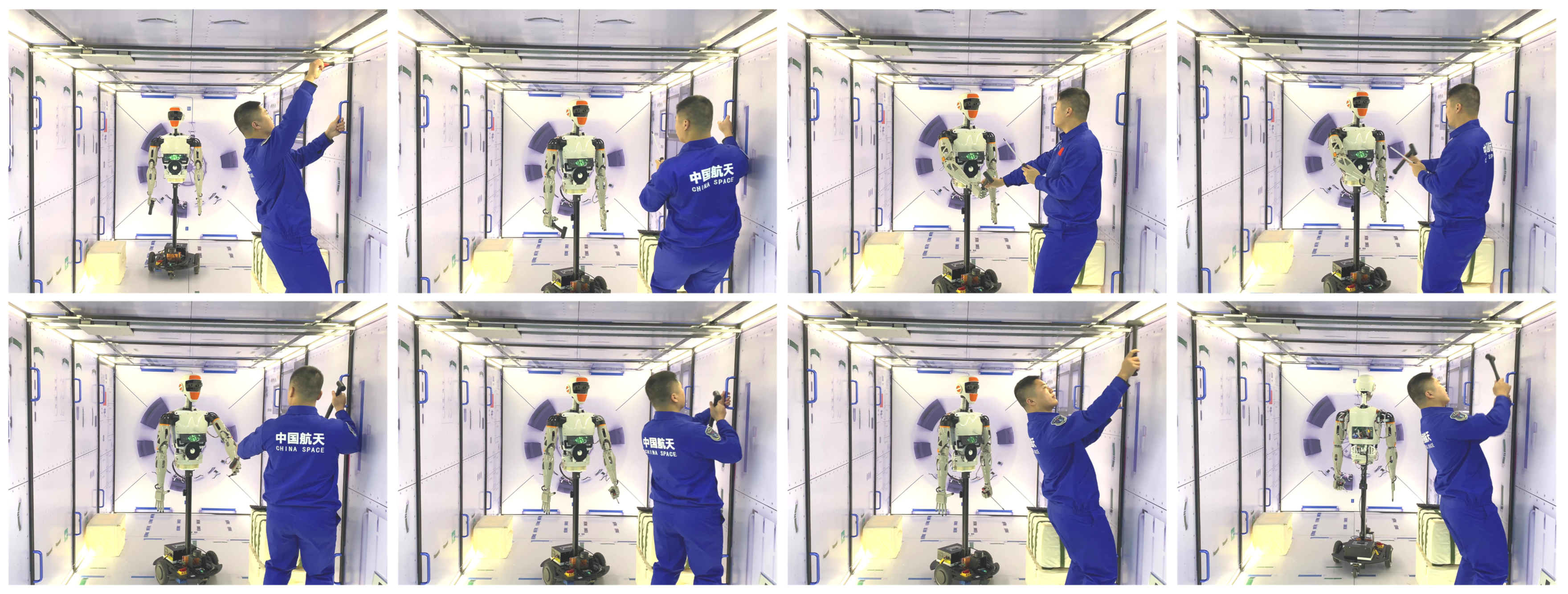
Figure 7e illustrates a scenario where Taikobot docks, utilizing its feet and the foot restraints in the cabin. When Taikobot has inserted its feet into the restraints, it can make the cabin apply opposite reaction forces to its left and right foot respectively through motion control of its zero-g leg system. The reaction forces including friction help establish a stable connection between the robot’s feet and the cabin.
As shown in Figure 7f–h, when a stable connection is established, the robot can adjust its height and inclination angle through the motion control of leg joints, and adjust its body orientation through the motion control of two additional waist joints.
4. Experimental Results and Discussion
Experiments were carried out to evaluate the proposed PFP locomotion strategy as well as the PFP motion planning and control method in simulation. Several core abilities of Taikobot in terms of astronaut–robot collaboration and object manipulation are also verified in a space station mock-up with a prototype developed for ground experiments.
4.1. Verification of the Intravehicular PFP Locomotion
We built a zero-g and multi-contact environment in Pybullet [25] to verify the feasibility and superiority of the PFP locomotion strategy and the bilevel motion planning and control method proposed in Section 3. In the simulation, the internal dimensions of the capsule are set to be 2 × 4 × 2 m.
- (1)
- Results of the Lower-Level Optimizer targeted at Desired Velocity
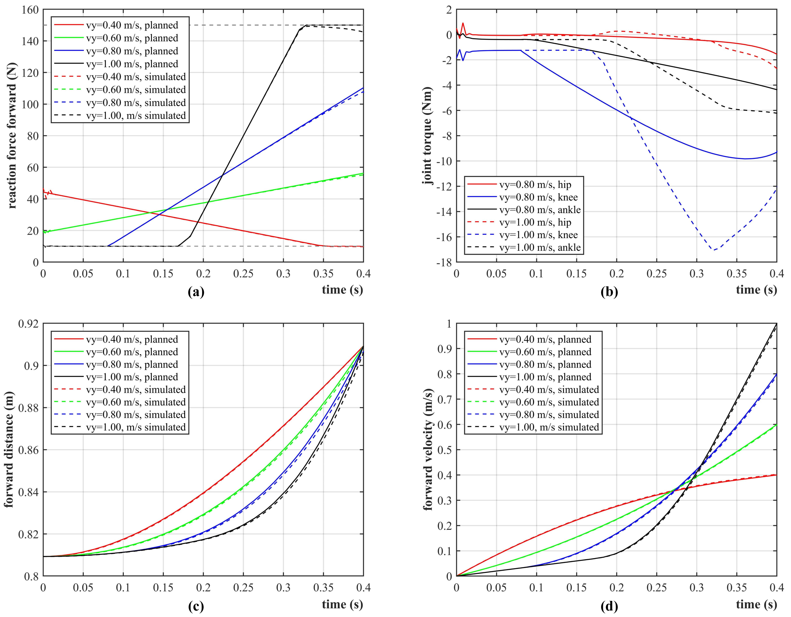
Firstly, we present the results where Taikobot implements pure forward locomotion with different velocities ranging from 0.4 to 1.0 m/s, which covers the usual moving speed of human astronauts in a space station. In the simulation, we set the robot’s maximum distance and duration of movement in the push-off phase to be 0.1 m and 0.4 s, respectively, according to Taikobot’s limb length, joint configuration, and expected velocity range. Figure 8a shows the planned and simulated curves of the reaction force normal to the contact surface constrained to 150 N. Figure 8b gives the joint torque solved in real time by inverse dynamics (14) to track the planned reaction forces. Thanks to the microgravity environment and the lightweight design of Taikobot, the joint torques are quite small. The largest torque values are required for the knee, and are less than 20 Nm, which in turn enables the use of miniaturized joints. Figure 8c,d give the COM position and velocity curves during the push-off phase, respectively. It can be verified that the simulated curves almost coincide with the planned trajectories.
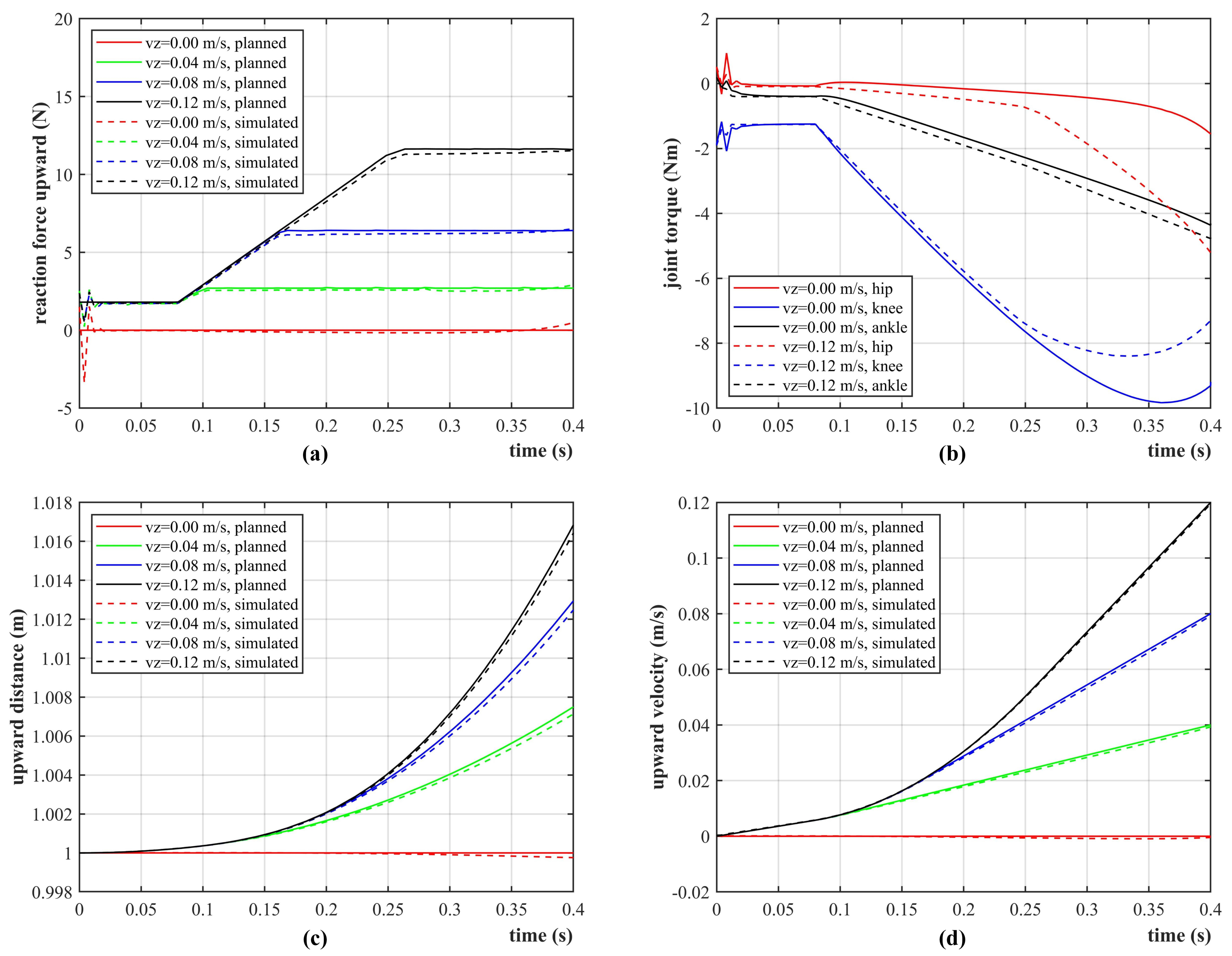
In addition to pure forward motion, Taikobot can also implement oblique PFP locomotion to reach target points at different heights. Figure 9 presents the planned and simulated curves with the same forward velocity (0.8 m/s) and various upward velocities in the push-off phase. In these cases, the reaction forces not only provide forward components, but also provide upward friction forces tangent to the contact surface. Figure 9a shows the planned and simulated curves of the friction forces, and all satisfy the non-slip constraints. It can be seen the simulated friction forces track the planned ones well by applying the solution of inverse dynamics (14). Likewise, the maximum joint torque is found in the knee, and does not exceed 10 Nm. As shown in Figure 9c,d, Taikobot can achieve the planned flight direction and velocities at departure, and the simulated and planned curves almost coincide.
- (2)
- Results of the Bilevel Optimizer targeted at Desired Parking Point
Apart from planning to transverse through the space station at desired velocities, we can also take the target parking location as our goal directly and use the bilevel optimizer (9) to generate trajectories for the whole PFP process.
As shown in Figure 5a, the target landing points are set to distribute within a range of ±0.5 m on the right inner wall. Figure 10 presents the planned and simulated curves of the PFP motion to park at various target points with the same forward velocity (0.8 m/s). Figure 10a shows the planned COM trajectories that start from the same initial point. Each trajectory can be divided into three phases: push-off (red solid line), flight (black solid line), and parking (red dotted line). The push-off phase takes 0.4 s and follows a red curved line. The curvature of the trajectory in the push-off phase is quite small since the optimized reaction forces are constrained within a thin friction zone. As shown in Figure 10b, Taikobot is able to track the planned velocities during the whole process. In the flight phase, the robot flies freely and moves continuously toward the target location. Taikobot also makes posture preparation before parking to reach the target and to reduce disturbance to its attitude due to the instantaneous impact. Figure 10c,d give the velocity and reaction force curves during the parking process by applying the deceleration controller (15). Taikobot parks within 0.2 s and its velocity decelerates to zero. The quick and stable parking control lays the basis for docking and thus performing subsequent onboard operations.
In this section, we have verified the PFP motion planning and control method in simulation, as well as the feasibility of this novel intravehicular locomotion strategy for Taikobot. PFP locomotion has many advantages over locomotion between handrails [26] in terms of flexibility, range of motion, etc. These simulation results have also verified that the overall mechatronic design, joint configuration, and joint capability of the robot can meet the basic needs of zero-g locomotion.
4.2. Experiments on Astronaut Assistance
In addition to simulation, we made a full-size prototype of Taikobot to test its manipulation skills and to verify its role in assisting human astronauts to improve their onboard working efficiency. The prototype uses differential-driven wheels instead of zero-g legs to facilitate ground experiments.
We first illustrate that Taikobot has the ability to manipulate a set of tools and interfaces designed for human beings. As shown in Figure 11, the robot can hold and manipulate a hammer and an electric screwdriver with one hand and transport a large package with dual-arm system, demonstrating robust interaction with the environment. Taikobot’s arm has a load capacity of about 2 kg on the Earth during ground experiments.
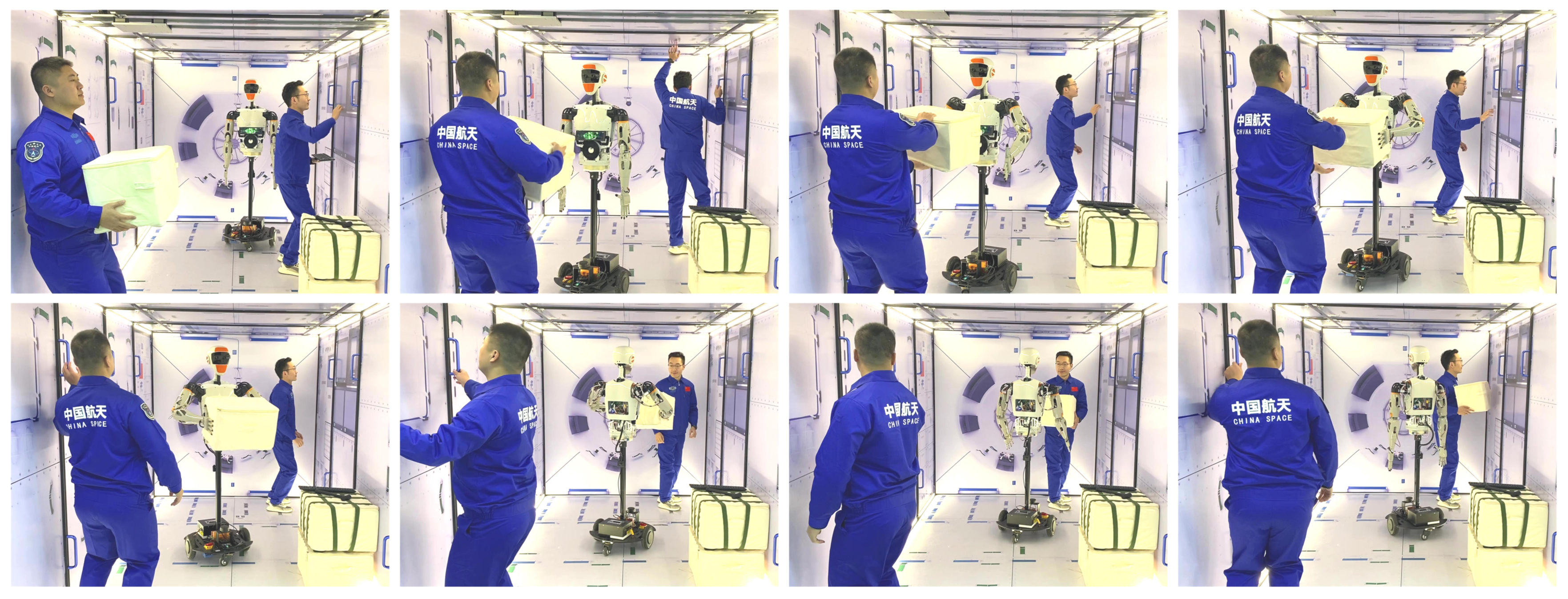
Finally, we give two examples where Taikobot assists and collaborates with human astronauts. Figure 12 illustrates a scenario where Taikobot accompanies an astronaut and helps deliver tools. The robot moves autonomously to the served astronaut, and hands over a hammer with its right hand. Then, it holds a tool returned by the served astronaut and moves back to its initial position. Figure 13 presents a scenario where Taikobot helps transport large cargoes in a space station. Taikobot can hold and transport large objects with dual arm system and collaborate with several astronauts in the meantime. Although simple, it requires several core abilities of Taikobot to accomplish these tasks such as stable in-cabin navigation, robust astronaut detection and tracking, and skillful object manipulation. With customized hierarchical computational architecture, all algorithms run in real time.
5. Conclusions
Taikobot is essentially a humanoid robotic assistant that can locomote and operate in microgravity through whole-body motion control. The lightweight design concept of the robot reduces launch cost and enhances safety during human–robot interaction. The anthropomorphic design concept allows the robot to share a set of intravehicular interfaces and facilitates human–robot collaboration. We carried out extensive simulation experiments on the PFP motion and verified the feasibility and advantages of this novel locomotion strategy in microgravity. The simulation results also verified that Taikobot’s overall mechatronic design, joint configuration, and joint capability can meet the basic needs to conduct various intravehicular activities. Experiments in the space station mockup also show that Taikobot can share the workload with human astronauts and has the potential to improve their onboard working efficiency.
At present, The development of Taikobot is still in the validation phase. The research and experiments in this paper will provide valuable data for the actual onboard deployment of the robot. In the near future, space robotic assistants like Taikobot will certainly play an important role in the never-ending process of space exploitation and utilization and contribute to the development of space economy.
Author Contributions
Conceptualization, Q.Z. and Y.Z.; methodology, Q.Z. and C.Z.; software, Q.Z. and C.Z.; validation, Q.Z.; formal analysis, Q.Z.; investigation, Q.Z. and C.Z.; resources, L.F. and Y.Z.; data curation, Q.Z.; writing—original draft preparation, Q.Z.; writing—review and editing, L.F. and Y.Z.; visualization, Q.Z. and C.Z.; supervision, L.F. and Y.Z.; project administration, L.F. and Y.Z.; funding acquisition, Y.Z. All authors have read and agreed to the published version of the manuscript.
Funding
This work is supported by Huzhou Institute of Zhejiang University under the Huzhou Distinguished Scholar Program (ZJIHI—KY0016).
Institutional Review Board Statement
Not applicable.
Informed Consent Statement
Not applicable.
Data Availability Statement
The data presented in this study are available on request from the corresponding author. The data are not publicly available due to intellectual property protection.
Conflicts of Interest
The authors declare no conflict of interest.
Abbreviations
The following abbreviations are used in this manuscript:
| COM | Center of Mass |
| PFP | Push–Flight–Park |
| PSA | Personal Satellite Assistant |
| SPHERES | Synchronized Position Hold, Engage, Reorient, Experimental Satellite |
| RFID | Radio Frequency Identification |
| DOF | Degrees of Freedom |
| WLAN | Wireless Local Area Network |
References
- Sgobba, T.; Kanki, B.; Clervoy, J.F. Space Safety and Human Performance, 1st ed.; Butterworth-Heinemann: Oxford, UK, 2018; pp. 357–376. Available online: https://www.elsevier.com/books/space-safety-and-human-performance/sgobba/978-0-08-101869-9 (accessed on 10 September 2022).
- Jason, C.; Marshall, S.; Douglas, C. Deep space gateway concept: Extending human presence into cislunar space. In Proceedings of the 2018 IEEE Aerospace Conference, Yellowstone Conference Center, Big Sky, MT, USA, 3–10 March 2018; Available online: https://ieeexplore.ieee.org/document/8396541 (accessed on 10 September 2022).
- Micco, V.; Amitrano, C. Effect of light quality and ionizing radiation on morphological and nutraceutical traits of sprouts for astronauts’ diet. Acta Astronaut. 2021, 185, 188–197. [Google Scholar] [CrossRef]
- Ayşe Meriç, Y.; Satyam, T. Space tourism: An initiative pushing limits. J. Tour. Leis. Hosp. 2021, 3, 38–46. [Google Scholar] [CrossRef]
- Ding, X.L.; Wang, Y.C.; Wang, Y.B. A review of structures, verification, and calibration technologies of space robotic systems for on-orbit servicing. Sci. China Technol. Sci. 2020, 64, 462–480. Available online: https://link.springer.com/article/10.1007/s11431-020-1737-4 (accessed on 10 September 2022). [CrossRef]
- Mitani, S.; Goto, M.; Konomura, R. Int-ball: Crew-supportive autonomous mobile camera robot on ISS/JEM. In Proceedings of the 2019 IEEE Aerospace Conference, Yellowstone Conference Center, Big Sky, MT, USA, 2–9 March 2019. [Google Scholar] [CrossRef]
- Smith, T.; Barlow, J.; Bualat, M. Astrobee: A new platform for free-flying robotics on the international space station. In Proceedings of the 13th International Symposium on Artificial Intelligence, Robotics, and Automation in Space, Beijing, China, 20–22 June 2016; Available online: https://ntrs.nasa.gov/citations/20160007769 (accessed on 10 September 2022).
- Dorais, G.A.; Gawdiak, Y. The personal satellite assistant: An internal spacecraft autonomous mobile monitor. In Proceedings of the 2003 IEEE Aerospace Conference, Big Sky, MT, USA, 8–15 March 2003. [Google Scholar] [CrossRef] [Green Version]
- Saenz-Otero, A.; Miller, D.W. Initial SPHERES operations aboard the International Space Station. In Proceedings of the 6th IAA Symposium on Small Satellites for Earth Observation, Berlin, Germany, 23–26 April 2008. [Google Scholar] [CrossRef]
- Park, I.W.; Smith, T.; Sanchez, H. Developing a 3-DOF compliant perching arm for a free-flying robot on the International Space Station. In Proceedings of the 2017 IEEE International Conference on Advanced Intelligent Mechatronics, Munich, Germany, 26–30 June 2017. [Google Scholar] [CrossRef] [Green Version]
- Zhang, R.; Wang, Z.K.; Zhang, Y.L. A person-following nanosatellite for in-cabin astronaut assistance: System design and deep-learning-based astronaut visual tracking implementation. Acta Astronaut. 2019, 162, 121–134. [Google Scholar] [CrossRef]
- Farrell, L.; Strawser, P.; Hambuchen, K. Supervisory control of a humanoid robot in microgravity for manipulation tasks. In Proceedings of the 2017 IEEE/RSJ International Conference on Intelligent Robots and Systems, Vancouver, BC, Canada, 24–28 September 2017. [Google Scholar] [CrossRef] [Green Version]
- Badger, J.M.; Strawser, P.; Farrell, L. Robonaut 2 and watson: Cognitive dexterity for future exploration. In Proceedings of the 2018 IEEE Aerospace Conference, Yellowstone Conference Center, Big Sky, MT, USA, 3–10 March 2018. [Google Scholar] [CrossRef]
- NASA Facts Robonaut 2, Technical Report. Available online: https://www.nasa.gov/sites/default/files/files/Robonaut2_508.pdf (accessed on 10 September 2022).
- Meet Skybot F-850, the Humanoid Robot Russia Is Launching into Space. Available online: https://www.space.com/russia-launching-humanoid-robot-into-space.html (accessed on 10 September 2022).
- Nicolaus, A.; Philip, S.; Kimberly, H. Valkyrie: Nasa’s first bipedal humanoid robot. J. Field Robot. 2015, 32, 397–419. [Google Scholar] [CrossRef]
- Angeliki, Z.; Loannis, K. Safety bounds in human robot interaction: A survey. Saf. Sci. 2020, 127, 104667. [Google Scholar] [CrossRef]
- Abdel-Nasser, S.; Panagiotis, N.K. Human-robot Interaction: A review and analysis on variable admittance control, safety, and perspectives. Machines 2022, 10, 591. Available online: https://www.mdpi.com/2075-1702/10/7/591 (accessed on 10 September 2022).
- Cheng, H.T.; Ji, G.F. Design and implementation of a low cost 3D printed humanoid robotic platform. In Proceedings of the 6th IEEE International Conference on Cyber Technology in Automation, Control and Intelligent Systems, Chengdu, China, 19–22 June 2016; Available online: https://ieeexplore.ieee.org/document/7574801 (accessed on 10 September 2022).
- Korovin, I.S.; Klimenko, A.B.; Kalyaev, I.A. An experience of the cognitive map-based classifier usage in astronaut’s emotional state monitoring. Acta Astronaut. 2021, 181, 537–543. [Google Scholar] [CrossRef]
- Kenji, K.; Hiroshi, K. Humanoid robot HRP-5P: An electrically actuated humanoid robot with high-power and wide-range joints. IEEE Robot. Autom. Lett. 2019, 4, 1431–1438. Available online: https://ieeexplore.ieee.org/document/8630006 (accessed on 10 September 2022).
- Dafarra, S.; Bertr, S.; Griffin, R.J. Non-linear trajectory optimization for large step-ups: Application to the humanoid robot atlas. In Proceedings of the 2020 IEEE/RSJ International Conference on Intelligent Robots and Systems, Las Vegas, NV, USA, 25–29 October 2020; Available online: https://ieeexplore.ieee.org/document/9341587 (accessed on 10 September 2022).
- Orin, D.E.; Ambarish, G. Centroidal momentum matrix of a humanoid robot: Structure and properties. In Proceedings of the 2008 IEEE/RSJ International Conference on Intelligent Robots and Systems, Nice, France, 22–26 September 2008. [Google Scholar] [CrossRef] [Green Version]
- Wu, Y.H.; Yu, Z.C.; Li, C.Y.; He, M.J.; Hua, B.; Chen, Z.M. Reinforcement learning in dual-arm trajectory planning for a free-floating space robot. Aerosp. Sci. Technol. 2020, 98, 105657. [Google Scholar] [CrossRef]
- Pybullet Homepage. Available online: https://pybullet.org/wordpress/ (accessed on 10 September 2022).
- Ramón, L.; Ramon, C.; Adrian, T. Trajectory optimization and control of a free-floating two-arm humanoid robot. J. Guid. Control Dyn. 2022. Available online: https://arc.aiaa.org/doi/abs/10.2514/1.G006828 (accessed on 10 September 2022).
Figure 1.
The robotic intravehicular assistant, Taikobot. (a) Taikobot is suspended in a space station mock-up. (b) A scenario where Taikobot helps astronauts transport cargoes with a dual arm system.
Figure 1.
The robotic intravehicular assistant, Taikobot. (a) Taikobot is suspended in a space station mock-up. (b) A scenario where Taikobot helps astronauts transport cargoes with a dual arm system.

Figure 2.
Overview of (a) Taikobot’s appearance, joint configuration and (b) dimensions in mm. Joint indexes are the same as in Table 1.
Figure 2.
Overview of (a) Taikobot’s appearance, joint configuration and (b) dimensions in mm. Joint indexes are the same as in Table 1.
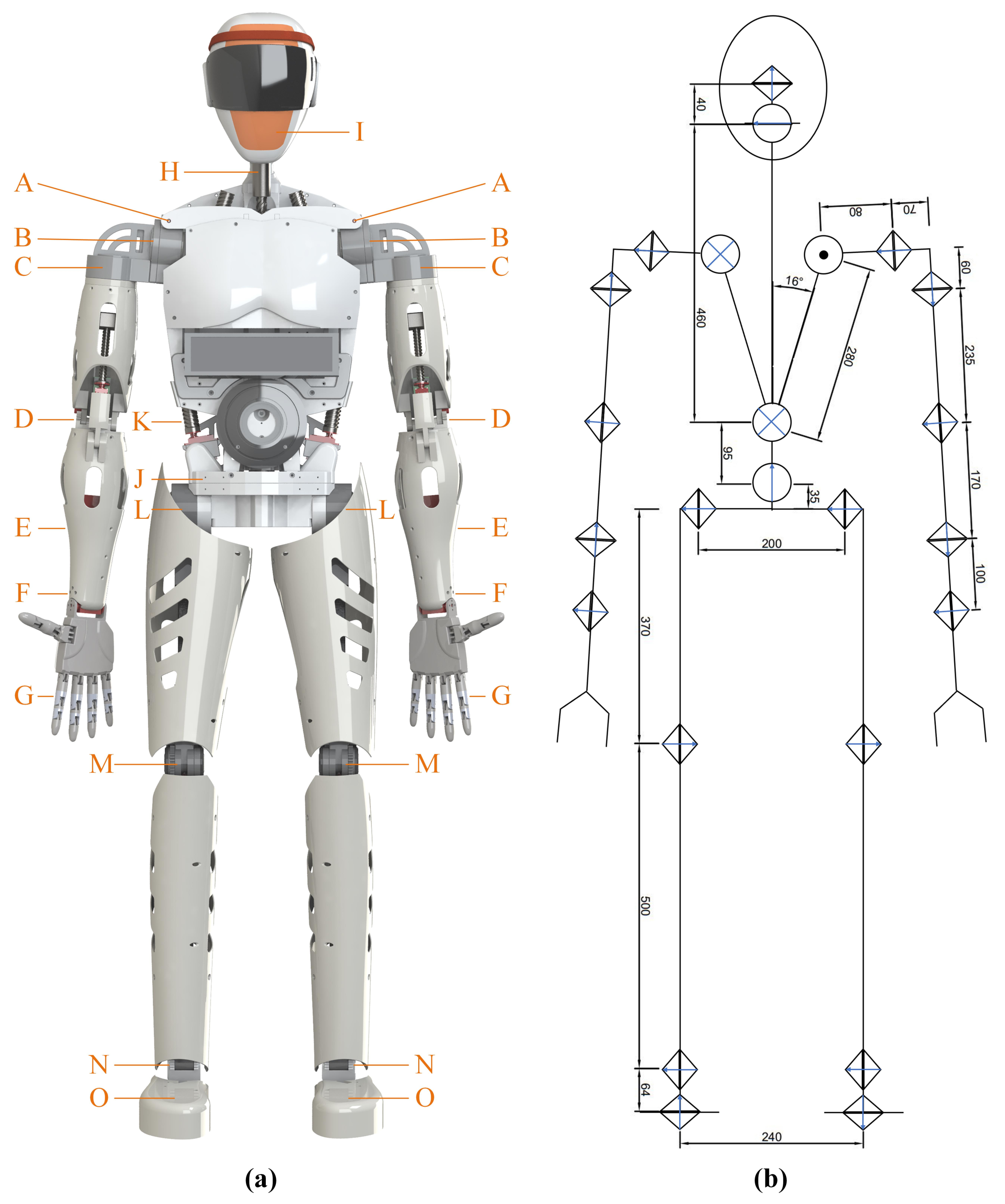
Figure 3.
Workspace of the (a) dual arm system and the (b) zero-g legs of Taikobot (dimensions in mm).
Figure 3.
Workspace of the (a) dual arm system and the (b) zero-g legs of Taikobot (dimensions in mm).
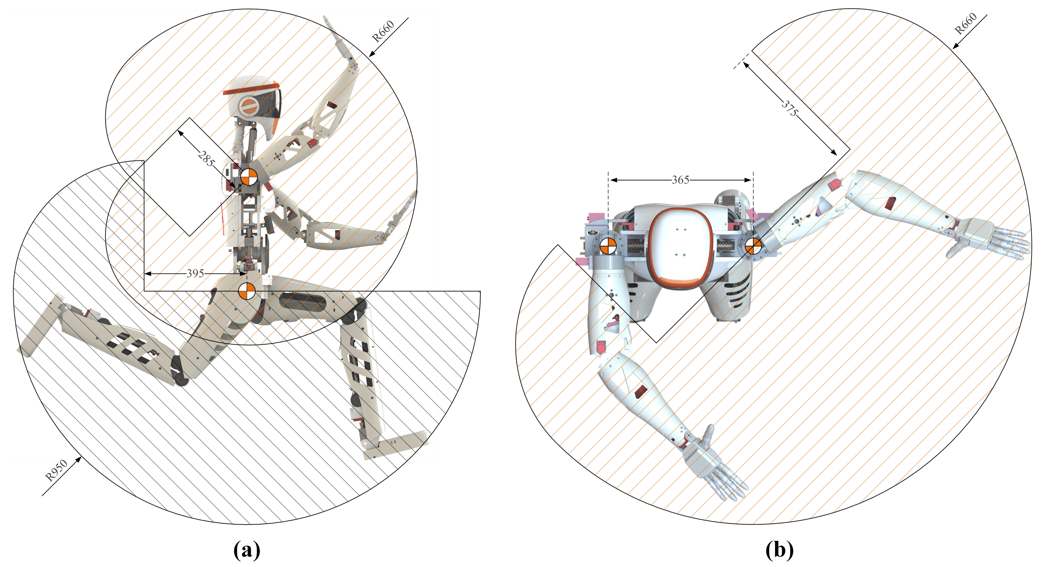
Figure 4.
Detailed design in terms of (a) the lightweight drive unit of joint C in the right shoulder, (b) the compact and self-consistent end effector, and (c) the supporting structure and driving mechanism in the knee.
Figure 4.
Detailed design in terms of (a) the lightweight drive unit of joint C in the right shoulder, (b) the compact and self-consistent end effector, and (c) the supporting structure and driving mechanism in the knee.
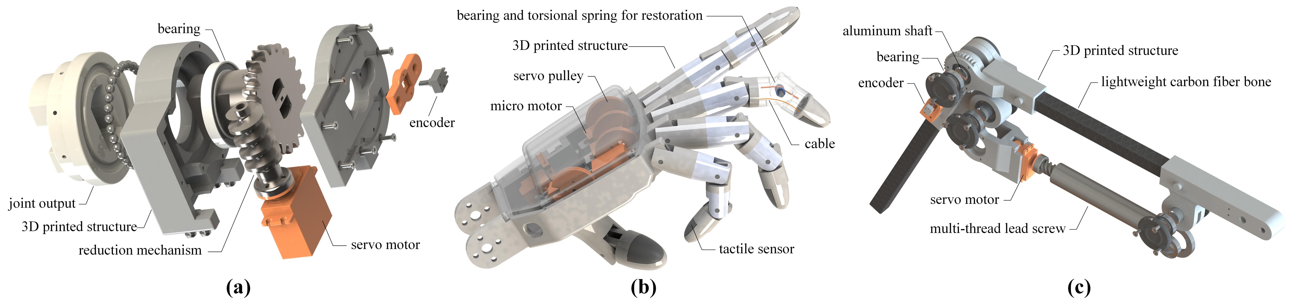
Figure 5.
The PFP locomotion in microgravity during (a,b) the push-off phase, (c,d) the flight or free-flying phase, and (e,f) the parking phase.
Figure 5.
The PFP locomotion in microgravity during (a,b) the push-off phase, (c,d) the flight or free-flying phase, and (e,f) the parking phase.
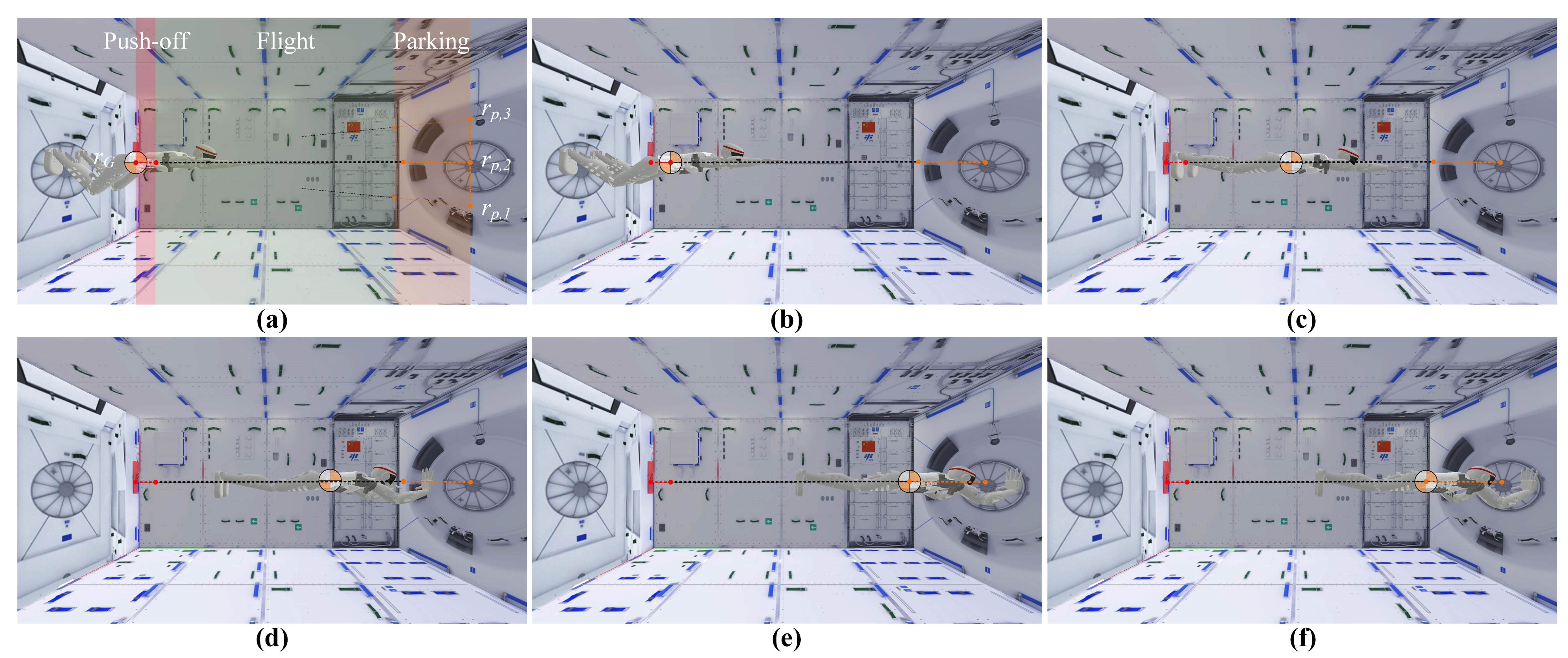
Figure 6.
Reaction forces exerted on Taikobot during the multi-contact PFP locomotion in the (a) push-off phase and (b) parking phase.
Figure 6.
Reaction forces exerted on Taikobot during the multi-contact PFP locomotion in the (a) push-off phase and (b) parking phase.
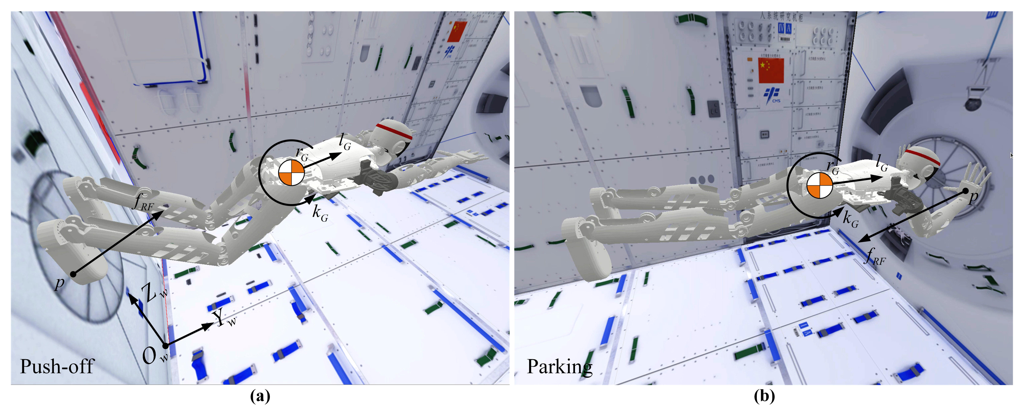
Figure 7.
Taikobot can dock with handrails (a–d) and foot restraints (e–h) and locomote locally in docking state.
Figure 7.
Taikobot can dock with handrails (a–d) and foot restraints (e–h) and locomote locally in docking state.
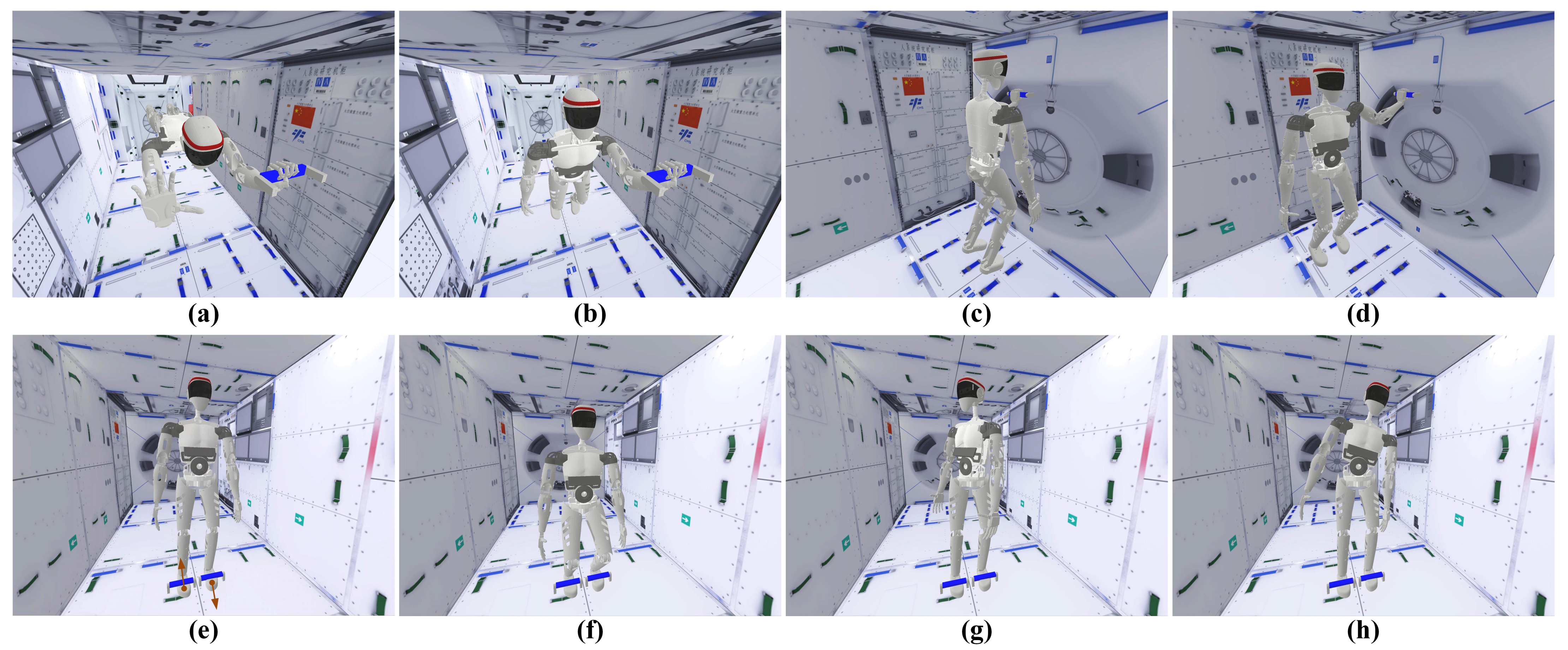
Figure 8.
Motion planning and control of the PFP locomotion targeted at various forward free-flying velocities. (a) reaction forces in the forward direction. (b) joint torques. (c) COM positions in the forward direction. (d) forward velocities.
Figure 8.
Motion planning and control of the PFP locomotion targeted at various forward free-flying velocities. (a) reaction forces in the forward direction. (b) joint torques. (c) COM positions in the forward direction. (d) forward velocities.

Figure 9.
Motion planning and control of the PFP locomotion targeted at various oblique free-flying velocities. (a) reaction forces in the upward direction. (b) joint torques. (c) COM positions in the upward direction. (d) upward velocities.
Figure 9.
Motion planning and control of the PFP locomotion targeted at various oblique free-flying velocities. (a) reaction forces in the upward direction. (b) joint torques. (c) COM positions in the upward direction. (d) upward velocities.

Figure 10.
Motion planning and control of the PFP locomotion strategy targeted at various docking points. (a) trajectories of the COM. (b) upward velocities. (c) velocities during the parking phase. (d) reaction forces during the parking phase.
Figure 10.
Motion planning and control of the PFP locomotion strategy targeted at various docking points. (a) trajectories of the COM. (b) upward velocities. (c) velocities during the parking phase. (d) reaction forces during the parking phase.
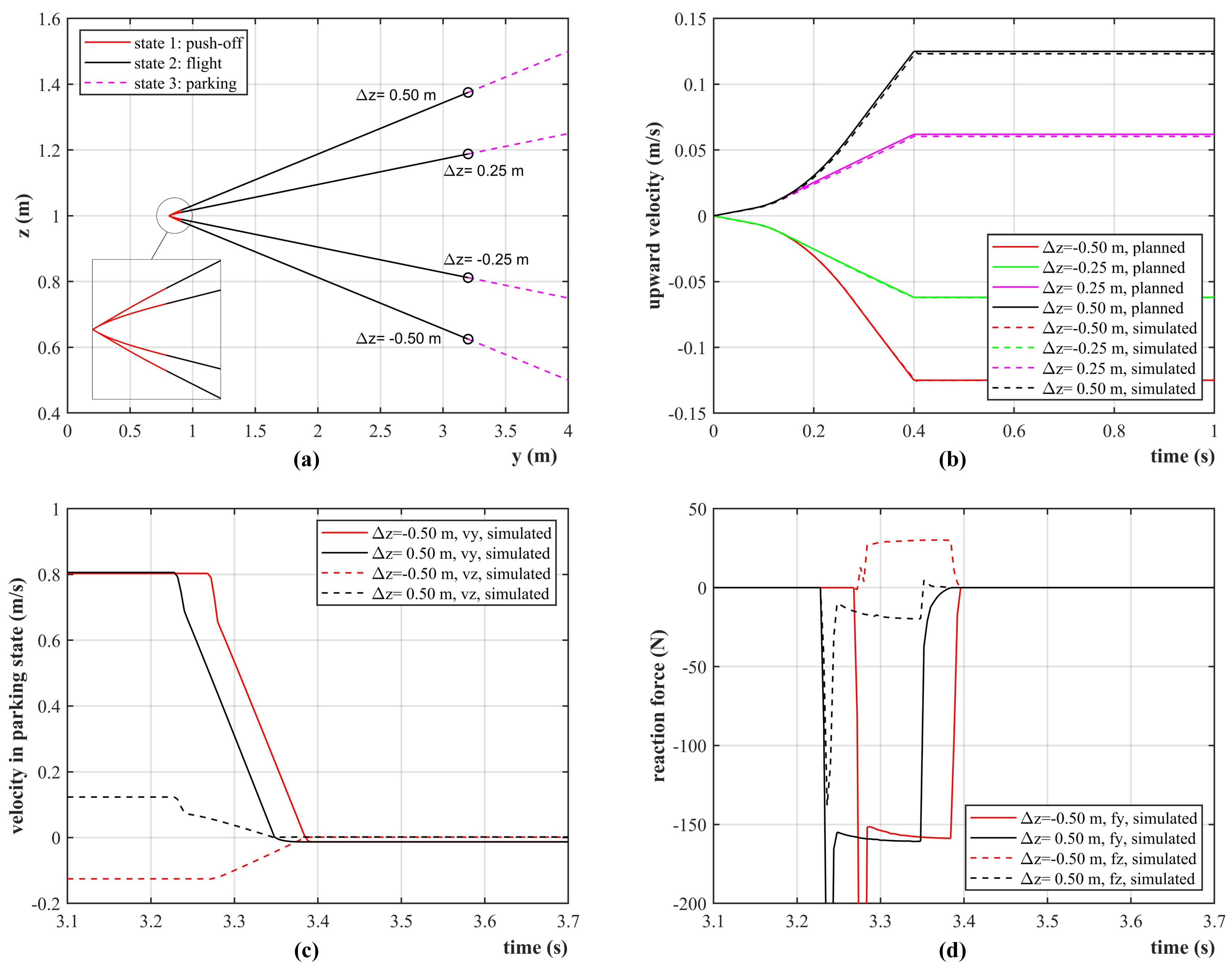
Figure 11.
Taikobot can handle a variety of tools and transport large cargoes with dual arm system.
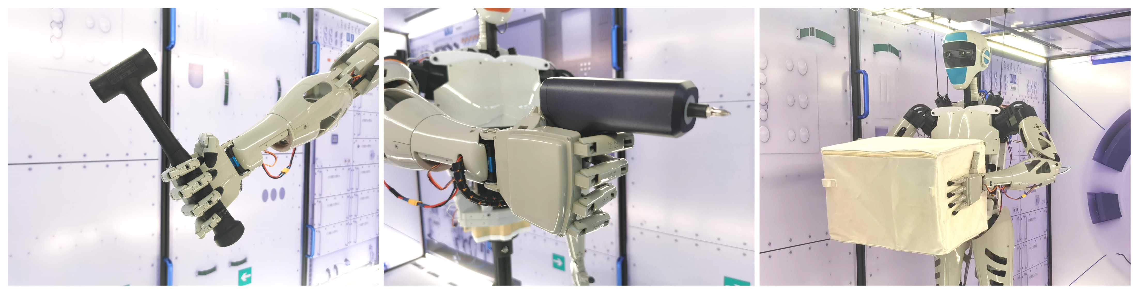
Figure 12.
Taikobot works side by side with a volunteer astronaut and helps deliver tools.

Figure 13.
Taikobot works along with several astronauts and helps transport large cargoes.

Table 1.
Summary of joint specifications for Taikobot.
| Joint Index | Transmission Mechanism | Max. Speed | Max. Torque | Range of Motion |
|---|---|---|---|---|
| A—shoulder roll | multi-thread lead screw | 40/s | 60 Nm | 0∼90 |
| B—shoulder pitch | worm gear | 40/s | 60 Nm | −45∼135 |
| C—shoulder yaw | worm gear | 40/s | 60 Nm | −135∼135 |
| D—elbow | multi-thread lead screw | 40/s | 50 Nm | 0∼90 |
| E—forearm | spur gear | 80/s | 20 Nm | −135∼135 |
| F—wrist | spur gear | 80/s | 20 Nm | −90∼90 |
| G—fingers | cable-driven | 80/s | 2 Nm | 0∼90 |
| H—neck pitch | multi-thread lead screw | 80/s | 20 Nm | −30∼30 |
| I—neck yaw | spur gear | 80/s | 20 Nm | −90∼90 |
| J—torso yaw | worm gear | 20/s | 120 Nm | −135∼135 |
| K—torso roll | multi-thread lead screw | 20/s | 120 Nm | −15∼15 |
| L—hip | worm gear | 40/s | 60 Nm | −90∼90 |
| M—knee | multi-thread lead screw | 40/s | 60 Nm | 0∼90 |
| N—ankle pitch | multi-thread lead screw | 40/s | 60 Nm | −30∼30 |
| O—ankle yaw | worm gear | 40/s | 60 Nm | −135∼135 |
Publisher’s Note: MDPI stays neutral with regard to jurisdictional claims in published maps and institutional affiliations. |
© 2022 by the authors. Licensee MDPI, Basel, Switzerland. This article is an open access article distributed under the terms and conditions of the Creative Commons Attribution (CC BY) license (https://creativecommons.org/licenses/by/4.0/).
Share and Cite
MDPI and ACS Style
Zhang, Q.; Zhao, C.; Fan, L.; Zhang, Y. Taikobot: A Full-Size and Free-Flying Humanoid Robot for Intravehicular Astronaut Assistance and Spacecraft Housekeeping. Machines 2022, 10, 933. https://doi.org/10.3390/machines10100933
AMA Style
Zhang Q, Zhao C, Fan L, Zhang Y. Taikobot: A Full-Size and Free-Flying Humanoid Robot for Intravehicular Astronaut Assistance and Spacecraft Housekeeping. Machines. 2022; 10(10):933. https://doi.org/10.3390/machines10100933
Chicago/Turabian StyleZhang, Qi, Cheng Zhao, Li Fan, and Yulin Zhang. 2022. "Taikobot: A Full-Size and Free-Flying Humanoid Robot for Intravehicular Astronaut Assistance and Spacecraft Housekeeping" Machines 10, no. 10: 933. https://doi.org/10.3390/machines10100933
Note that from the first issue of 2016, this journal uses article numbers instead of page numbers. See further details here.