Study on an Automatic Parking Method Based on the Sliding Mode Variable Structure and Fuzzy Logical Control


College of Mechatronics and Control Engineering, Shenzhen University, Shenzhen 518060, China
*
Authors to whom correspondence should be addressed.
Symmetry 2018, 10(10), 523; https://doi.org/10.3390/sym10100523
Submission received: 29 September 2018
/
Revised: 13 October 2018
/
Accepted: 16 October 2018
/
Published: 19 October 2018
(This article belongs to the Special Issue Fuzzy Techniques for Decision Making 2018)
Abstract
:This paper discusses an automatic parking control method based on the combination of the sliding mode variable structure control (SMVSC) and fuzzy logical control. SMVSC is applied to drive the vehicle from a random initial position and pose, to the designated parking position and pose. Then, the vehicle is driven from the designated parking position to the target parking slot using the method of fuzzy logical control, whose rules are limited to the range of the effective initial position. To combine SMVSC with the fuzzy logical control, the experimental results demonstrate that effective parking can be guaranteed, even if the initial position is out of the effective parking area of the fuzzy logical control.
1. Introduction
As a key part of autonomous driving technologies, automatic parking technology can release the human driver from complicated parking procedures and can park more efficiently. Accordingly, automatic parking technology has gained a lot of attention, and the correlative research is increasing [1].
According to the procedures of parking, the research of automatic parking technology has been divided into two major aspects, which include parking slots detection, and parking path planning and tracking. In the aspect of parking slots detection, Huang, C.C. and Wang, S.J. proposed a three-layer Bayesian hierarchical detection framework to detect parking slots [2]. Suhr, J.K. proposed a method based on estimating parallel line pairs so as to detect a parking slot [3], and used a hierarchical tree structure method to recognize various parking slot markings [4]. Yu Cheng proposed an approach for parking slots detection based on video images [5]. Jung, H.G. and Yun, H.L. proposed a method based on target position-designation to mark the parking slot [6]. In another aspect, research on parking path planning and tracking have been developed, for example, Vorobieva, H. proposed a path-planning method based on corresponding geometry and tracking the path with a controller, based on traveled distance [7]. Li, B. and Wang, K. used a simultaneous dynamic optimization method to optimize the maneuver planning [8]. Xu, J. proposed an automatic parking method based on computer vision [9]. Sugeno, M. and Murakami, K. designed fuzzy logical controller rules, based on the experience of human drivers, to park the vehicle [10]. On this foundation, Zhan, Y.N. and Collins, E.G. optimized the membership functions of the fuzzy logical controller by using a genetic algorithm to park the vehicle more efficiently [11]. Yin, Y.A. also improved the fuzzy controller based on images using a genetic algorithm [12].
The fuzzy logical control applied in automatic parking has gained a lot of attention, since Kong, S.G. applied an adaptive fuzzy logical control algorithm to back up a truck-and-trailer in 1992 [13]. Liang, Z. designed an automatic parking path tracking controller based on self-organizing fuzzy control [14]. Xiong, Z.B. proposed an automatic parking algorithm based on the preview fuzzy control [15]. Grzegorzewski, P. proposed an efficient algorithm for checking separability, which can be easily applied in practice [16]. The fuzzy logical control applied in automatic parking becomes the mainstream method, with the advantage of improving robustness against uncertainties and of simulating the nonlinear control of the human driver [17].
However, fuzzy logical control in automatic parking still has some limitations. In reality, the uncertainty of a vehicle’s initial position results in the fuzzy logical controller not being able to park the vehicle successfully, for example, if the initial parking position is outside of the range of the effective parking position where the fuzzy logical controller can park the vehicle successfully. The effective parking position depends on the rules of the fuzzy logical controller. In other words, if the fuzzy logical controller is confirmed, the range of the effective parking position will be confirmed. Hence, the confirmed fuzzy logical controller cannot park successfully if the vehicle is outside the range of the effective position.
Our objective is solving this problem (the confirmed fuzzy logical controller cannot park successfully if the vehicle is outside of the range of the effective position) by sliding the mode variable structure control (SMVSC). The SMVSC is insensitive to the disturbance and responds quickly [18], so it is often used to track trajectory [19]. Recently, Yue, M. proposed a method based on a model predictive control (MPC) and SMVSC in order to track the coordinated trajectory of vehicles [20]. The solution can be divided into two steps, with the first step using the SMVSC method drive the vehicle from an initial position to the range of an effective parking position, and the second step parking the vehicle from the effective parking position to the target slot.
In this paper, a method based on the sliding mode variable structure control (SMVSC) and fuzzy logical control is proposed in order to park a car, from an initial position where it is outside the range of an effective position. The procedures can be divided as follows. SMVSC drives the vehicle to the range of the effective position to prepare for parking. Afterwards, the fuzzy logical controller parks the vehicle into the target slot. The results, based on MATLAB, show that the control method combining the SMVSC with fuzzy logical control can realize parking from a random initial position, where it is outside the range of an effective parking position.
In this paper, Section 2 presents an algorithm of SMVSC, to drive the vehicle from a random initial position to the effective position. Section 3 discusses the fuzzy logical controller that is used to park the vehicle from the designated position. Section 4 describes the results of the experiment, based on MATLAB Simulink. The conclusion remarks are presented in Section 5.
2. Algorithm of the Sliding Mode Variable Structure Control
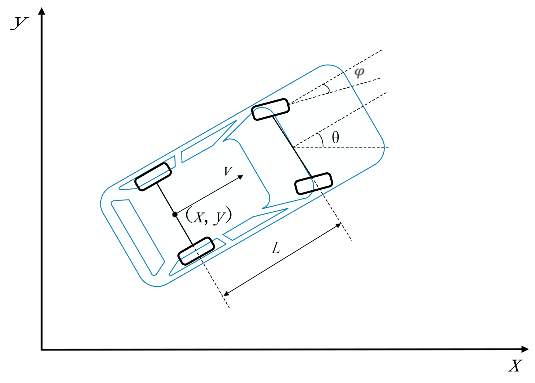
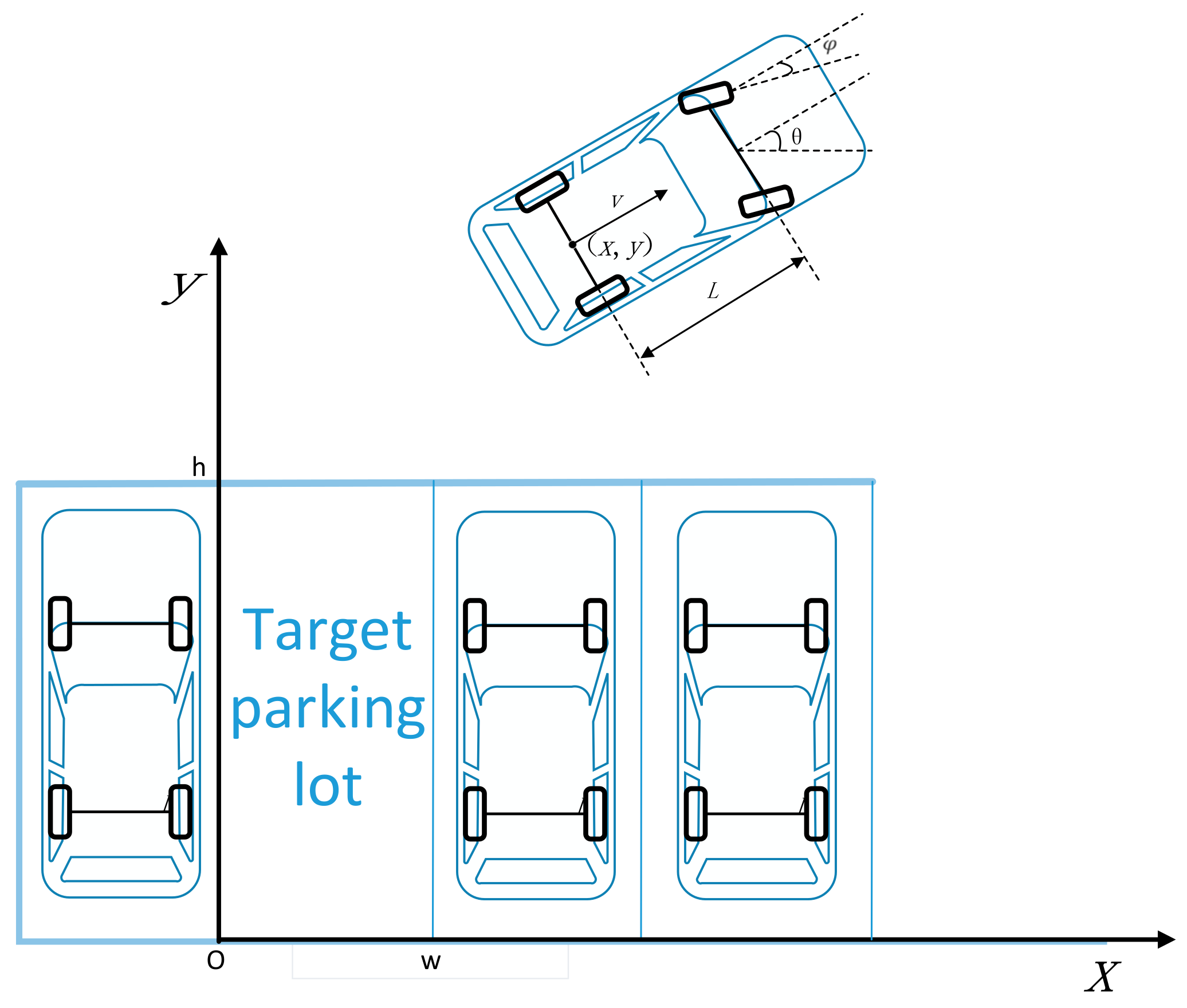
The vehicle’s position and pose in the 2D plane can be defined as . As shown in Figure 1, are the coordinates of the center point of a vehicle’s rear axle, θ is the course of the vehicle, is the front-wheel corner, L is the wheelbase, and V is the speed of the vehicle. The dynamical equations of the vehicle can be expressed in Equation (1), as follows:
If is small enough, then and ; thus, the dynamical equations of the vehicle are shown as follows:
where ω is the yaw rate.
The dynamical equations in matrix form are governed by the following equations:
where and .
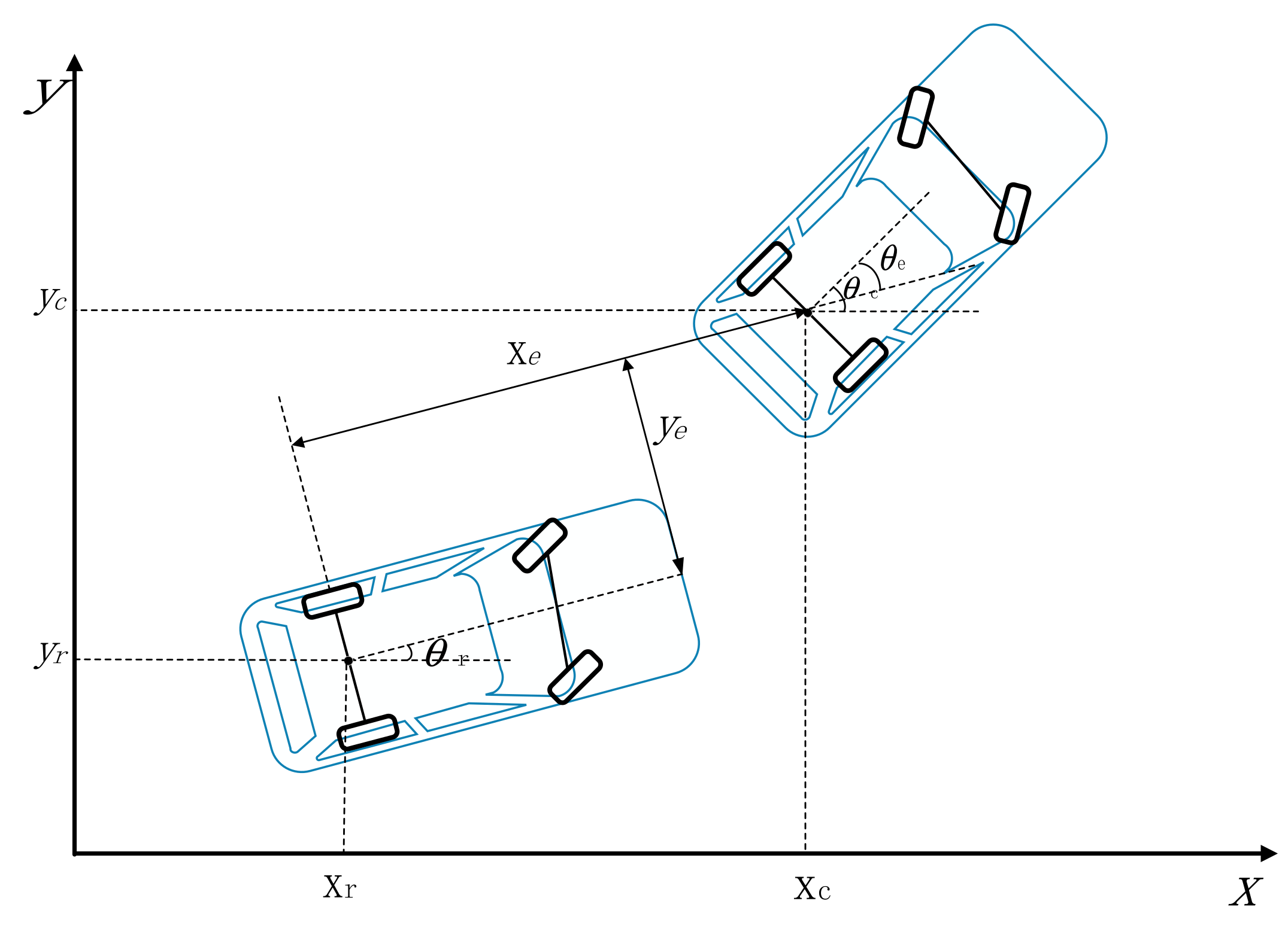
As shown in Figure 2, is the vehicle’s initial position and pose, and is the vehicle’s ideal position and pose. According to the geometric relationship between and , the error can be defined as Equation (4), as follows:
where and are and , respectively.
According to the derivative of error, Equation (4), and the dynamical equation, Equation (2), the differential equation of error is proposed as Equation (5), as follows:
where and are the ideal speed and ideal yaw rate, respectively. and are the current speed and current yaw rate, respectively.
It can be pointed out from the above analysis that, according to the numerical values of , , and , SMVSC aims to output and to make converge to zero.
Lemma 1.
If , then the Lyapunov function can be described using Equation (6), as follows:
with the hypothesis of , , according to the Lemma 1, (if and only if , then the equality holds), hence .
It can be seen that if converges to zero and converges to , then converges to zero, thus the switching function is designed using Equation (7), as follows:
We designed a sliding mode controller to let and converge to zero, which means that converges to zero and converges to to make and converge to zero.
The constant rate reaching law can be expressed as follows:
It is unavoidable for the sliding mode control to generate chattering effect, but the chattering effect can be decreased by replacing Equation (8) with Equation (9), as follows:
where is a positive number.
Thus, the constant rate reaching law for Equation (7) can be described using Equation (10), as follows:
Using Equation (5), as well as the derivative of Equations (7) and (10), Equation (11) is obtained, as follows:
where , , .
Changing the form of Equation (11), the control law is designed and shown, as follows:
The function relationship between and is given by Equation (2), and we changed the form of Equation (2), resulting in Equation (13), as follows:
In this section, the purpose of SMVSC is for driving a vehicle from a random initial position and pose, to the ideal position and pose [22,23]. As shown in Figure 3, represents the ideal position and pose. and are the ideal yaw rate and ideal speed of the vehicle, respectively. According to Equation (4), by combining the ideal position and pose with the current position and pose , we defined the error of position and pose , as shown in Figure 2, which is the input of SMVSC. The output of SMVSC, and , which depend on and , , decide the corner of front wheel, . Lastly, according to and , SMVSC controls the vehicle.
3. Fuzzy Logical Controller
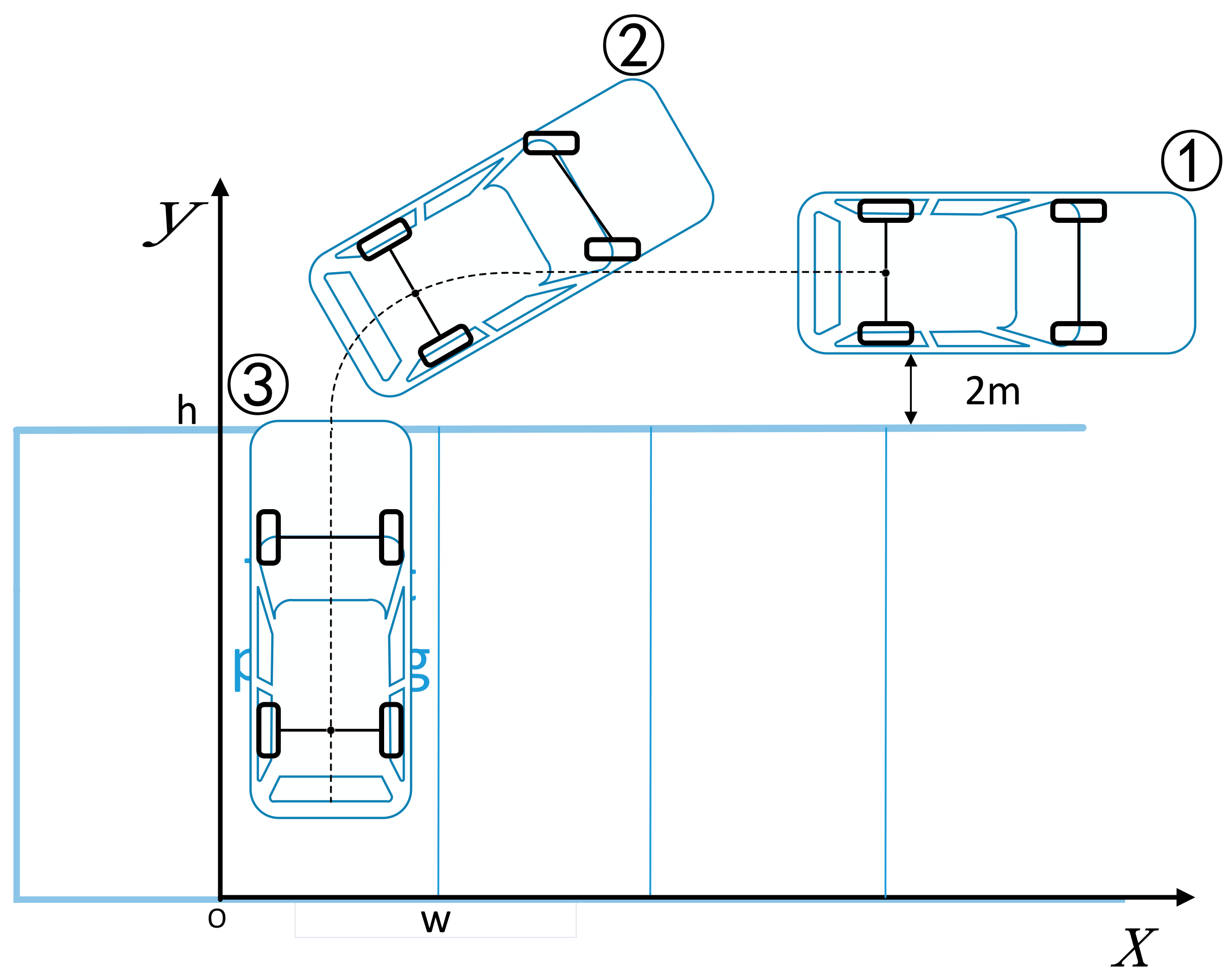
As shown in Figure 4, w is the weight of the parking slot and h is the height of the parking slot. are the coordinates of the center point of the vehicle’s rear axle, and is the course of the vehicle. In order to adapt to the different sizes of the parking slot, we replaced with [24], which is defined by Equation (14), as follows:
There are three inputs for the fuzzy logical controller,, , and . The output is the front-wheel corner, . The parking speed is the constant. The diagram of the fuzzy logical controller is shown in Figure 5, as follows:
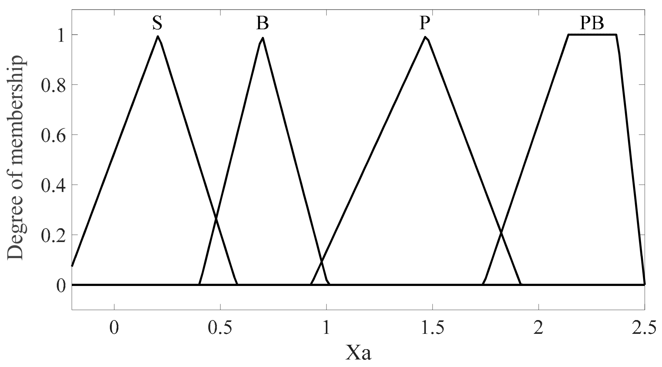
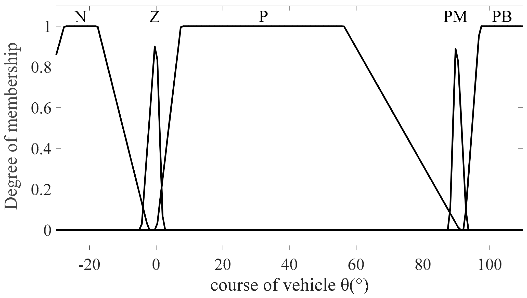
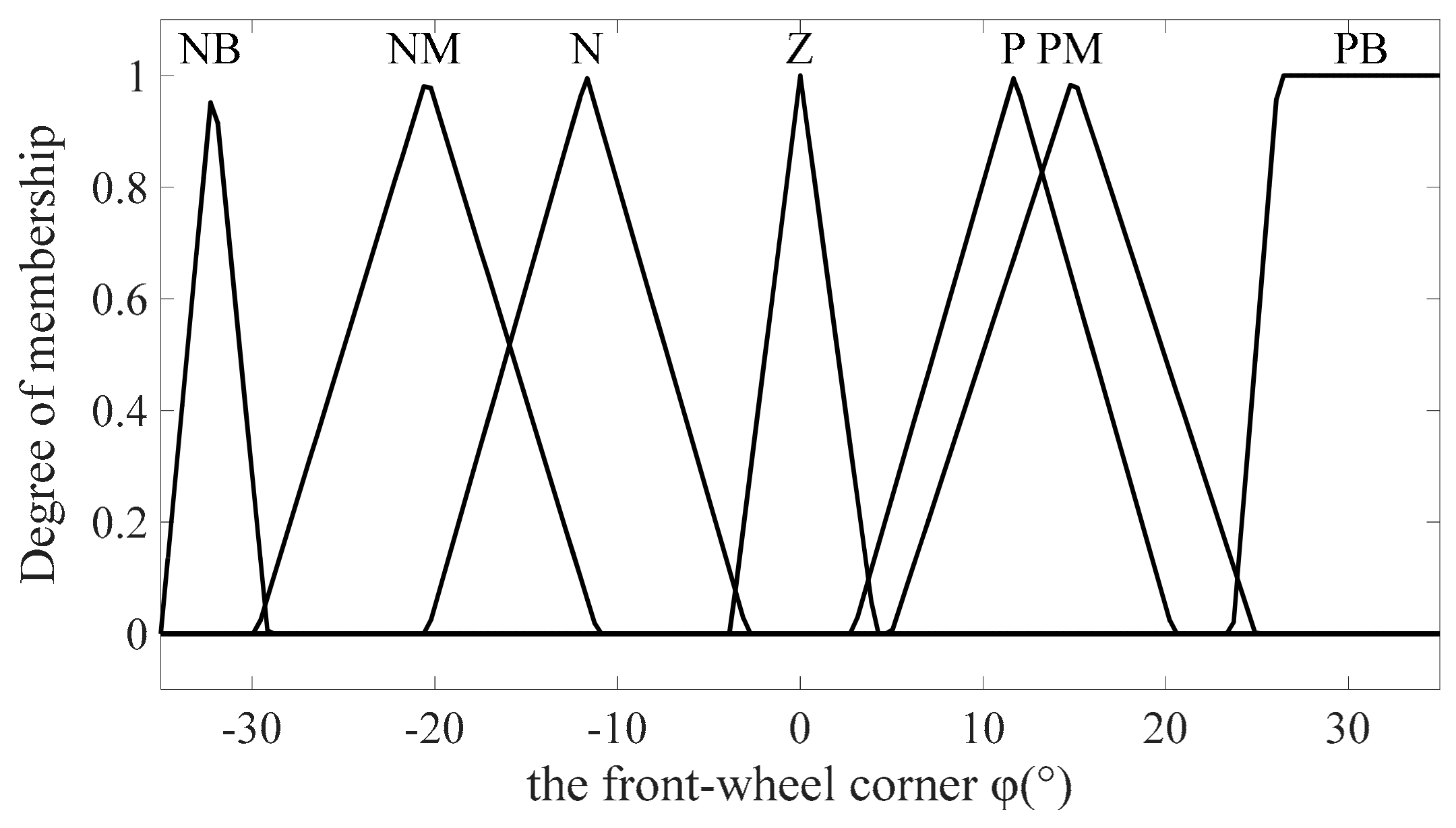
The algorithm of the fuzzy logical controller is the Mamdani algorithm [25], and the membership functions are shown in Figure 6, Figure 7, Figure 8 and Figure 9, the abbreviations in Figure 6, Figure 7, Figure 8 and Figure 9 are the name of membership function, and the parameters of the membership functions are shown in Table 1.
The parking strategy is described in Figure 10. Leave 2 m between the vehicle and the parking slot. Keep the vehicle in reverse, with the speed of v (m/s), until the distance between the extended line of the parking slot line and the tail of the vehicle reach 1 m. Then, let the front-wheel corner, , turn 35°. When the course of the vehicle, , reaches 90°, it returns to .
According to the parking strategy, the fuzzy rules are designed and are shown in Table 2, Table 3, Table 4 and Table 5.
There are nine rules in the fuzzy rule base.
Finally, the center average is used in the defuzzifier to calculate .
4. Results
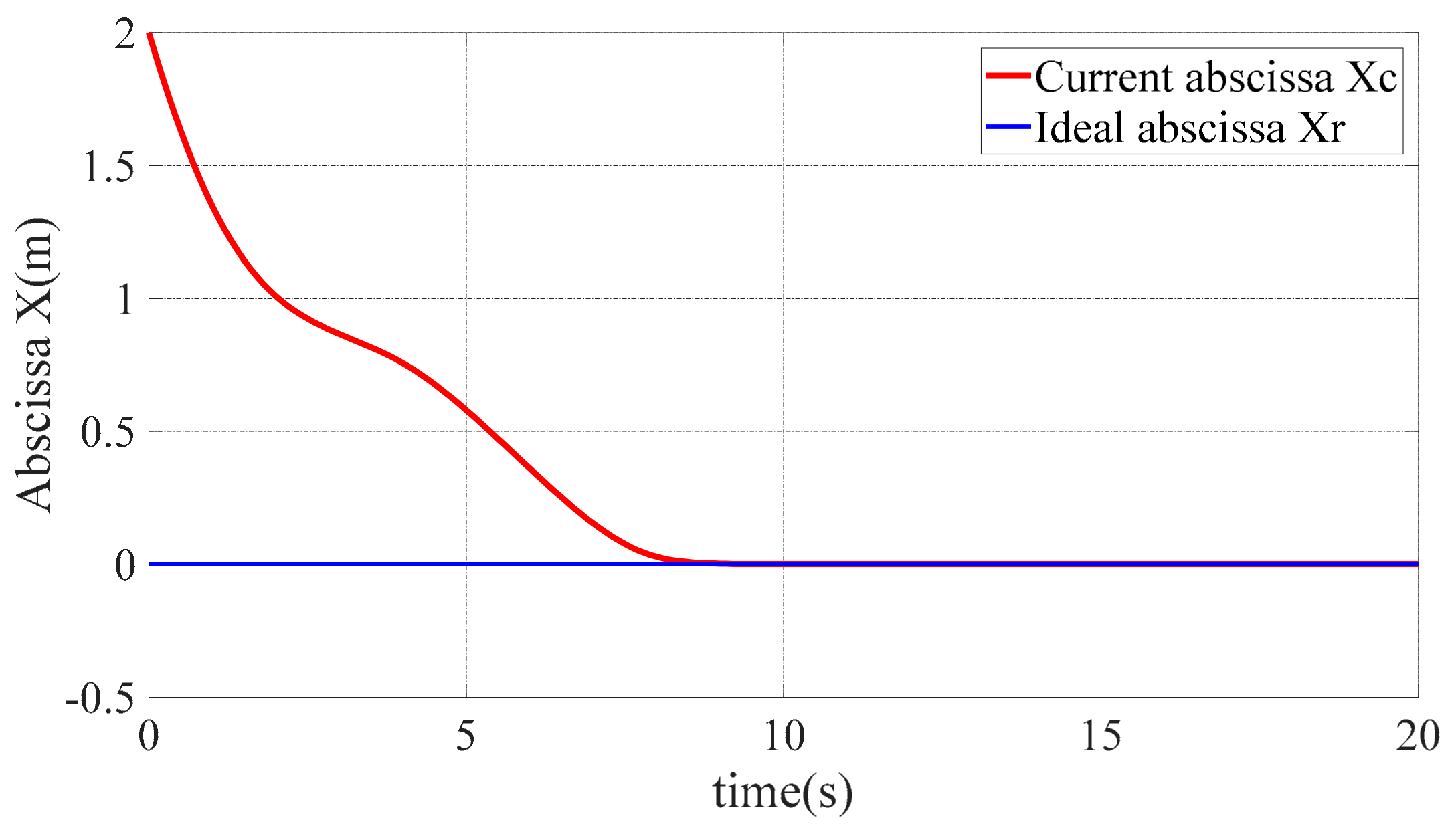
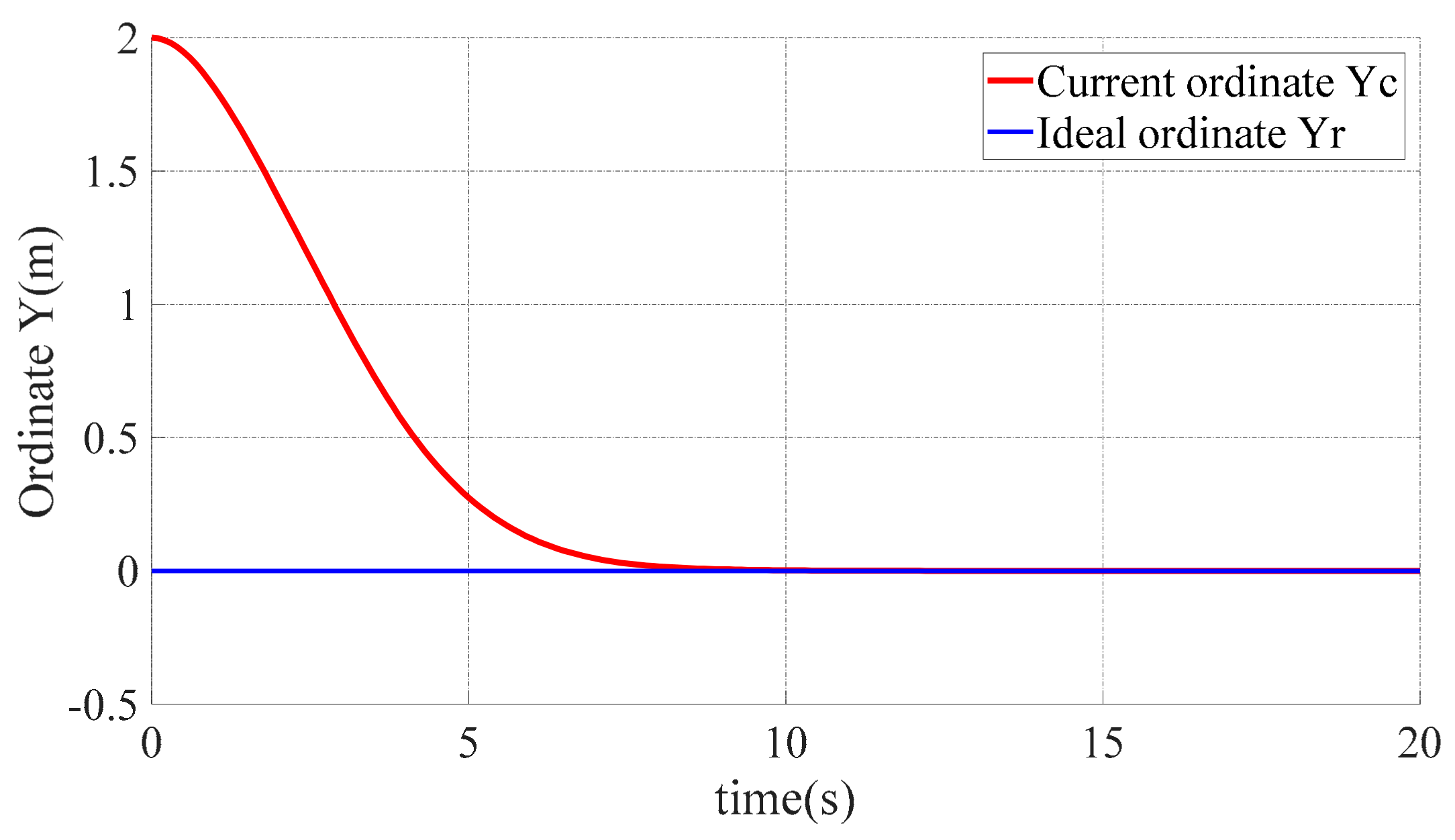
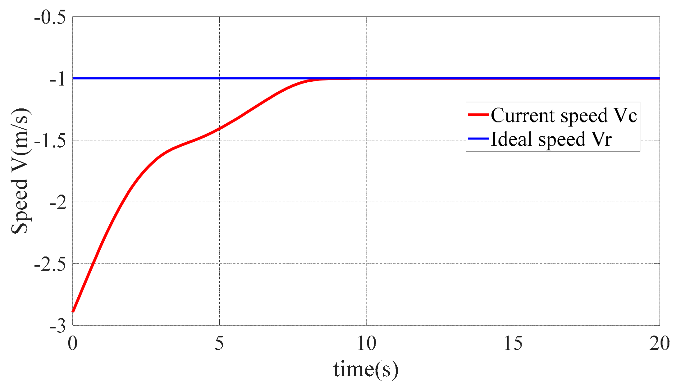
In this section, we show the effect of SMVSC and the fuzzy logical controller, respectively. The simulating parameters of SMVSC are shown as follows: , , , , , and . The results are shown in Figure 11, Figure 12, Figure 13, Figure 14 and Figure 15.
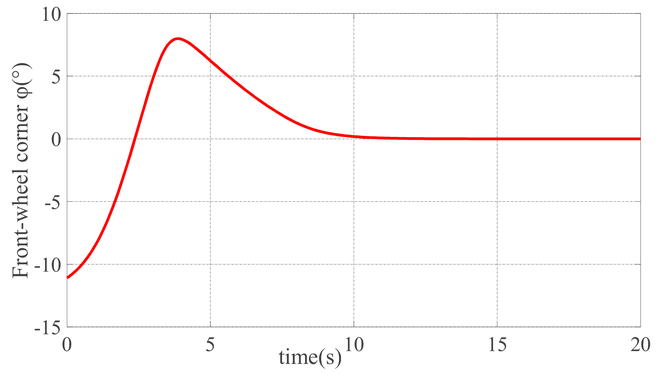
As we can see from Figure 11, Figure 12 and Figure 13, the ideal position and pose and the initial position and pose are changed from the initial error of to , by the control laws and , which are shown in Figure 14 and Figure 15. In other words, according to control laws and , the vehicle is driven from the initial position and pose to the ideal position and pose . It is noteworthy that the convergence time of in ten seconds. In Figure 14 and Figure 15, the curvilinear trend is smooth, so that it can be implemented in reality [26].
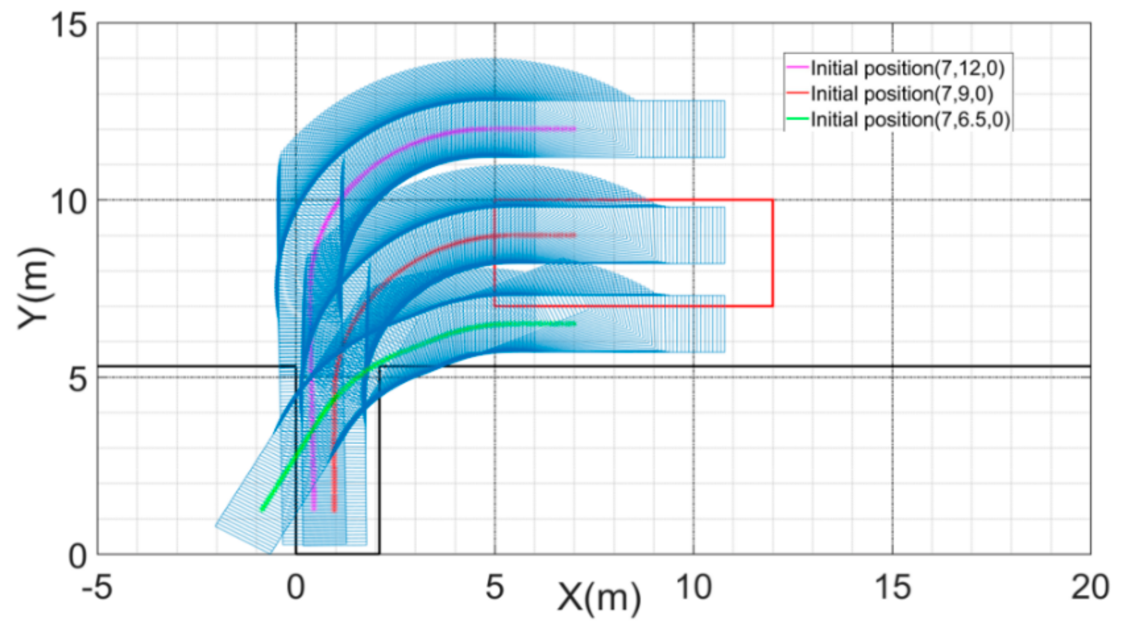
The result of the fuzzy logical controller is given in Figure 16, which is the trajectory of the vehicle’s center point of the rear axle.
As shown in Figure 16, the simulating parameters are shown as follows: = 2.5, , speed v = −1 m/s, the initial position and pose of magenta trajectory is , the initial position and pose of green trajectory is , and both of the trajectories are outside the area of the effective parking position, so they park unsuccessfully. The initial position and pose of the red trajectory is , which is inside the red box, which allows for parking successfully. According to the experiments, if the initial position is within the area of the red box, shown in Figure 16, the fuzzy logical controller described in Section 3 can park the vehicle successfully.
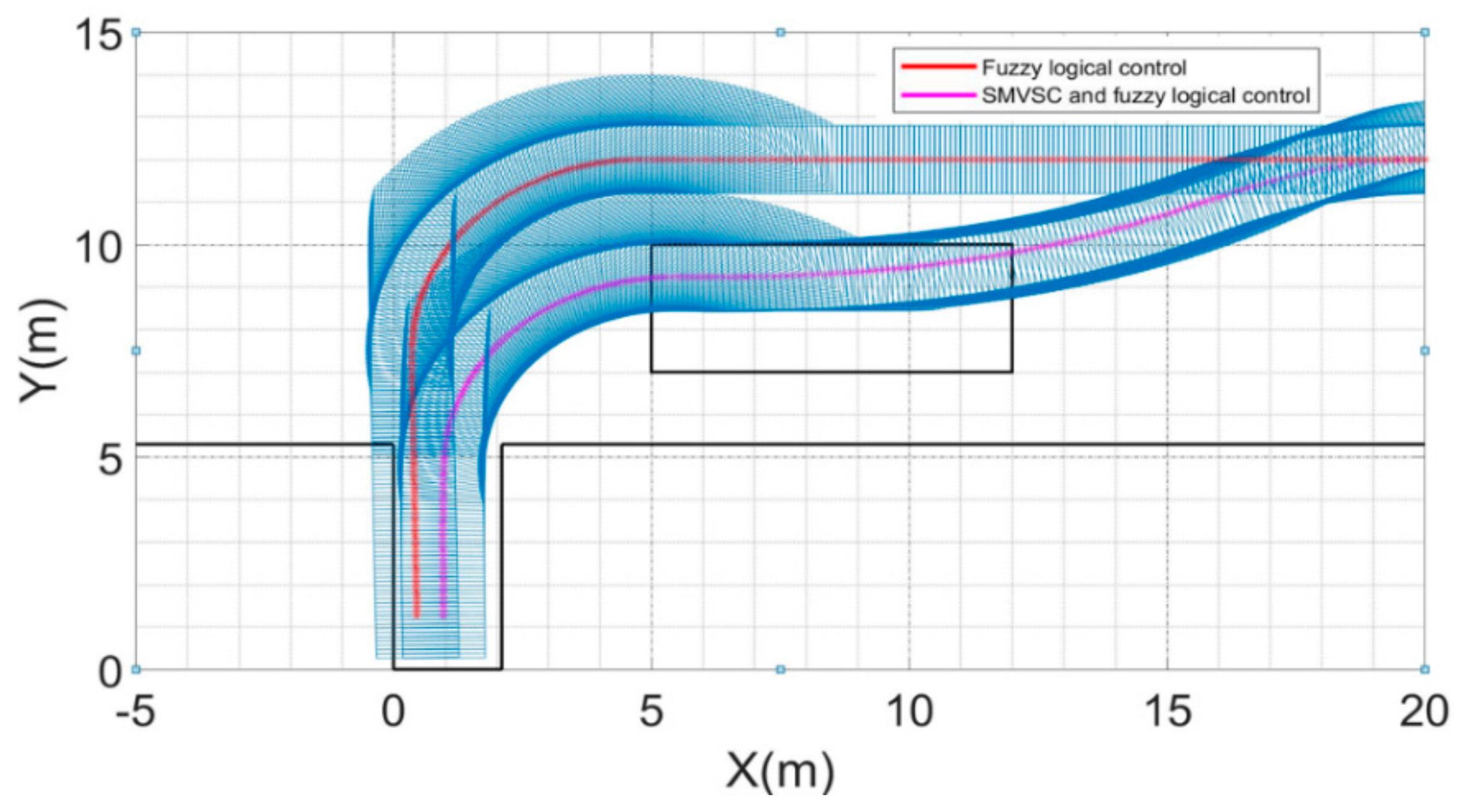
As discussed in the Section 1 (Introduction), this paper aims to park the vehicle from an initial position, which is out of the black box, by combining SMVSC with the fuzzy logical control. Figure 17 shows the effect of this method.
The magenta trajectory is controlled by the hybrid method. The red trajectory is controlled by the fuzzy logical controller, which is the same as the hybrid method. The simulating parameters of Figure 17 are shown as follows: the ideal position and pose are the same as that of Figure 16 . The initial position and pose are , which is out of black box. The result of the simulating shows that the hybrid method can park the vehicle into the target slot successfully, but the fuzzy logical control cannot park successfully (the left side of the vehicle is not in the slot). The result shows that the hybrid method can expand the range of the effective parking position.
5. Conclusions
A control parking method, which combines SMVSC with the fuzzy logical control, is proposed in this paper. This method aims to expand the range of the effective parking position, which is confirmed by the fuzzy logical controller. The disadvantage of the fuzzy logical control is that the range of the effective initial position and pose are limited to its rules. In other words, the fuzzy logical controller cannot park the vehicle when the initial position is out of the effective initial position. The aim of this paper to solve this problem, of driving the vehicle from a random initial position to the effective parking position using the mothed of SMVSC, and parking the vehicle from the effective parking position using the method of fuzzy logical control.
SMVSC can control a vehicle from a random initial position to an effective parking position in limited amount of time; furthermore, the curve of the control laws is smooth enough to implement in reality, and the chattering effect is decreased. The results also show that the fuzzy logical controller has nine rules, which is according to the strategy of parking, and can park the vehicle from the effective parking position (area of red box). By comparing the fuzzy logical control and the hybrid control method, the experimental results verified that the fuzzy logical control cannot park from an initial position outside the range of an effective parking position, but the hybrid method can. In short, parking from a random initial position to parking outside of the effective parking position is realized by the hybrid method of combining the SMVSC and fuzzy logical control.
Author Contributions
Y.X. designed the main body of the study and revised the manuscript; Z.L. and X.S. wrote the main body of the paper; W.J. and B.W. guided the system design and analyzed the data; and Y.W. helped to revise the paper.
Funding
This research was funded by the National Natural Science Foundation of China (no. 61403259) and the Science and Technology Research and Development Foundation of Shenzhen (no. JCYJ20170302142107025).
Conflicts of Interest
The authors declare no conflict of interest.
References
- Wang, W.; Song, Y.; Zhang, J.; Deng, H. Automatic parking of vehicles: A review of literatures. Int. J. Autom. Technol. 2014, 15, 967–978. [Google Scholar] [CrossRef]
- Huang, C.C.; Wang, S.J. A Hierarchical Bayesian Generation Framework for Vacant Parking Space Detection. IEEE Trans. Circ. Syst. Video Technol. 2010, 1770–1785. [Google Scholar] [CrossRef]
- Suhr, J.K.; Jung, H.G. Automatic Parking Space Detection and Tracking for Underground and Indoor Environments. IEEE Trans. Ind. Electron. 2016, 63, 5687–5698. [Google Scholar] [CrossRef]
- Suhr, J.K.; Jung, H.G. Full-automatic recognition of various parking slot markings using a hierarchical tree structure. Opt. Eng. 2013, 52, 7203. [Google Scholar] [CrossRef]
- Li, Y.C.; Yan, J.L.; Wang, M.S.; Han, D.T. Approach for parking spaces detection based on video images. Comput. Eng. Des. 2012, 33, 281–285. [Google Scholar]
- Jung, H.G.; Yun, H.L.; Kim, J. Uniform User Interface for Semiautomatic Parking Slot Marking Recognition. IEEE Trans. Veh. Technol. 2010, 59, 616–626. [Google Scholar] [CrossRef]
- Vorobieva, H.; Glaser, S.; Minoiu-Enache, N.; Mammar, S. Automatic Parallel Parking in Tiny Spots: Path Planning and Control. IEEE Trans. Intell. Transp. Syst. 2015, 16, 396–410. [Google Scholar] [CrossRef]
- Li, B.; Wang, K.; Shao, Z. Time-Optimal Maneuver Planning in Automatic Parallel Parking Using a Simultaneous Dynamic Optimization Approach. IEEE Trans. Intell. Transp. Syst. 2016, 17, 3263–3274. [Google Scholar] [CrossRef] [Green Version]
- Xu, J.; Chen, G.; Xie, M. Vision-guided automatic parking for smart car. In Proceedings of the IEEE Intelligent Vehicles Symposium 2000, Dearborn, MI, USA, 5 October 2002; pp. 725–730. [Google Scholar] [Green Version]
- Sugeno, M.; Murakami, K. Fuzzy parking control of model car. In Proceedings of the 23rd IEEE Conference on Decision and Control, Las Vegas, Nevada, USA, 12–14 December 1984; pp. 902–903. [Google Scholar]
- Zhao, Y.; Emmanuel, G.C., Jr. Robust automatic parallel parking in tight spaces via fuzzy logic. Robot. Auton. Syst. 2005, 51, 111–127. [Google Scholar] [CrossRef]
- Aye, Y.Y.; Watanabe, K.; Maeyama, S.; Nagai, I. An automatic parking system using an optimized image-based fuzzy controller by genetic algorithms. Artif. Life Robot. 2016, 22, 1–6. [Google Scholar] [CrossRef]
- Kong, S.G.; Kosko, B. Adaptive fuzzy systems for backing up a truck-and-trailer. IEEE Trans. Neural Netw. 1992, 3, 211–223. [Google Scholar] [CrossRef] [PubMed]
- Liang, Z.; Zheng, G.Q.; Li, J.-S. Tracking Controller Based on Self-Organizing Fuzzy Control. Fire Control Commun. Control 2013, 38, 50–54. [Google Scholar]
- Xiong, Z.B.; Yang, W.; Ding, K.; Liang, F.-H.; Zheng, L.; Li, Y.-S.; Chang’an Auto Global R&D Center; Chang’an Automobile Co., Ltd.; The State Key Laboratory of Mechanical Transmissions, Chongqing University. Research on the Auto Parking Algorithm Based on the Preview Fuzzy Control. J. Chongqing Univ. Technol. 2017, 17, 323–325. [Google Scholar]
- Grzegorzewski, P. On Separability of Fuzzy Relations. Int. J. Fuzzy Logic Intell. Syst. 2017, 17, 137–144. [Google Scholar] [CrossRef] [Green Version]
- Zhao, Y.; Collins, E.G. Fuzzy parallel parking control of autonomous ground vehicles in tight spaces. In Proceedings of the IEEE International Symposium on Intelligent Control, Houston, TX, USA, 8 October 2003; pp. 811–816. [Google Scholar]
- Edwards, C.; Spurgeon, S.K. Sliding Mode Control: Theory and Applications; Taylor & Francis: Boca Raton, FL, USA, 1988. [Google Scholar]
- Schindele, D.; Aschemann, H. Trajectory tracking of a pneumatically driven parallel robot using higher-order SMC. IEEE Int. Conf. Methods Models Autom. Robot. 2010, 387–392. [Google Scholar] [CrossRef]
- Yue, M.; Hou, X.; Fan, M.; Jia, R. Coordinated trajectory tracking control for an underactuated tractor-trailer vehicle via MPC and SMC approaches. In Proceedings of the 2017 2nd International Conference on Advanced Robotics and Mechatronics (ICARM), Hefei, China, 27–31 August 2017; pp. 82–87. [Google Scholar]
- Tahara, J.I.; Tsuboi, K.; Sawano, T.; Nagata, Y. An adaptive VSS control method with integral type switching gain. In Proceedings of the IASTED International Conference Robotics and Applications, Clearwater, FL, USA, 19–22 November 2001; pp. 106–111. [Google Scholar]
- Jiang, L.; Zhongwei, W.U. Sliding Mode Control for Intelligent Vehicle Trajectory Tracking Based on Reaching Law. Trans. Chin. Soc. Agric. Mach. 2018, 49, 381–386. [Google Scholar]
- He, H.; Peng, J.; Xiong, R.; Fan, H. An Acceleration Slip Regulation Strategy for Four-Wheel Drive Electric Vehicles Based on Sliding Mode Control. Energies 2014, 7, 3748–3763. [Google Scholar] [CrossRef] [Green Version]
- Lanza, J.; Sánchez, L.; Gutiérrez, V.; Galache, J.A.; Santana, J.R.; Sotres, P.; Muñoz, L. Smart City Services over a Future Internet Platform Based on Internet of Things and Cloud: The Smart Parking Case. Energies 2016, 9, 719. [Google Scholar] [CrossRef]
- Mamdani, E.H. Application of fuzzy algorithms for control of simple dynamic plant. Proc. Inst. Electr. Eng. 1974, 121, 1585–1588. [Google Scholar] [CrossRef]
- Hua, Y.; Jiang, H.; Cai, Y.; Zhang, X.; Ma, S.; Wu, D. Path Tracking Control of Automatic Parking Cloud Model Considering the Influence of Time-delay. Math. Probl. Eng. 2017, 2017, 6590383. [Google Scholar] [CrossRef]
Figure 1.
Mode of vehicle.

Figure 2.
Diagram of the error between and

Figure 3.
Relationship among variables of the sliding mode variable structure control (SMVSC).
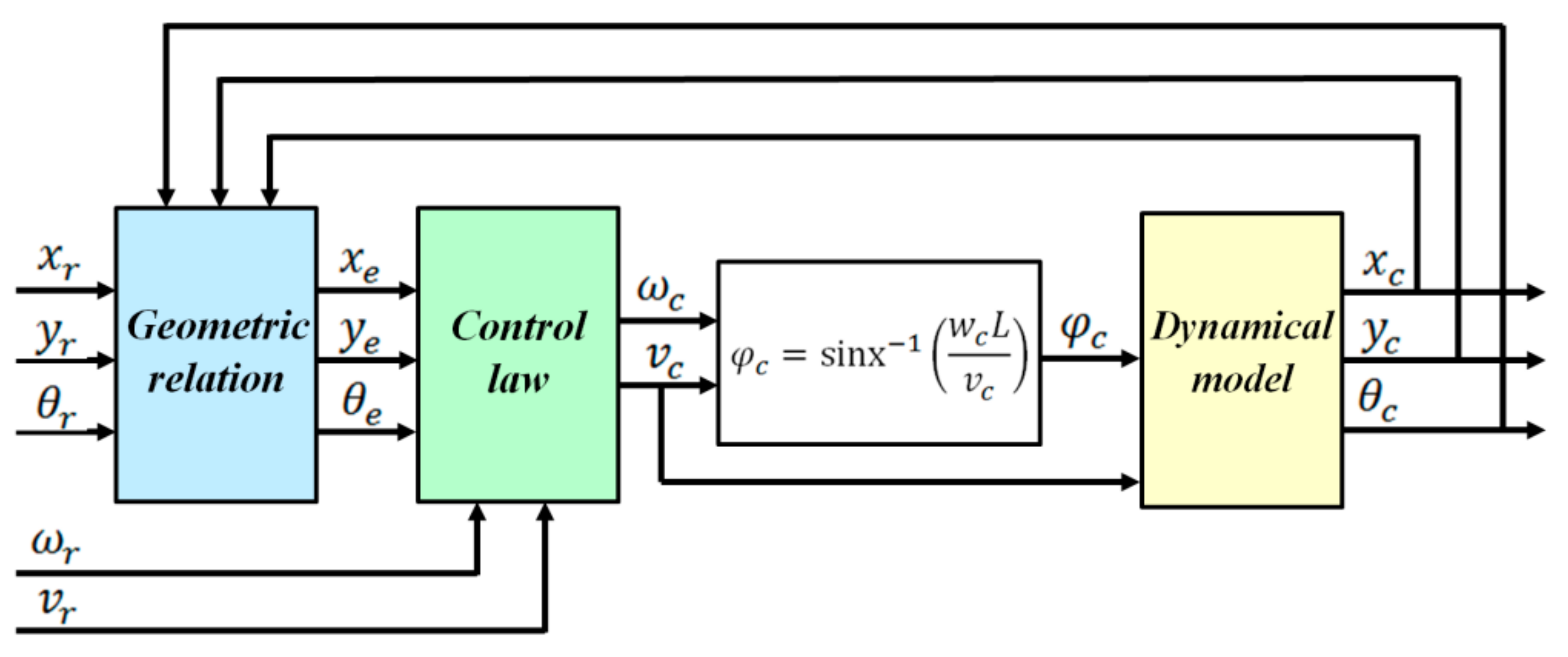
Figure 4.
Coordinate system and target parking slot.

Figure 5.
Diagram of the fuzzy logical controller.

Figure 6.
Generated membership function for

Figure 7.
Generated membership function for
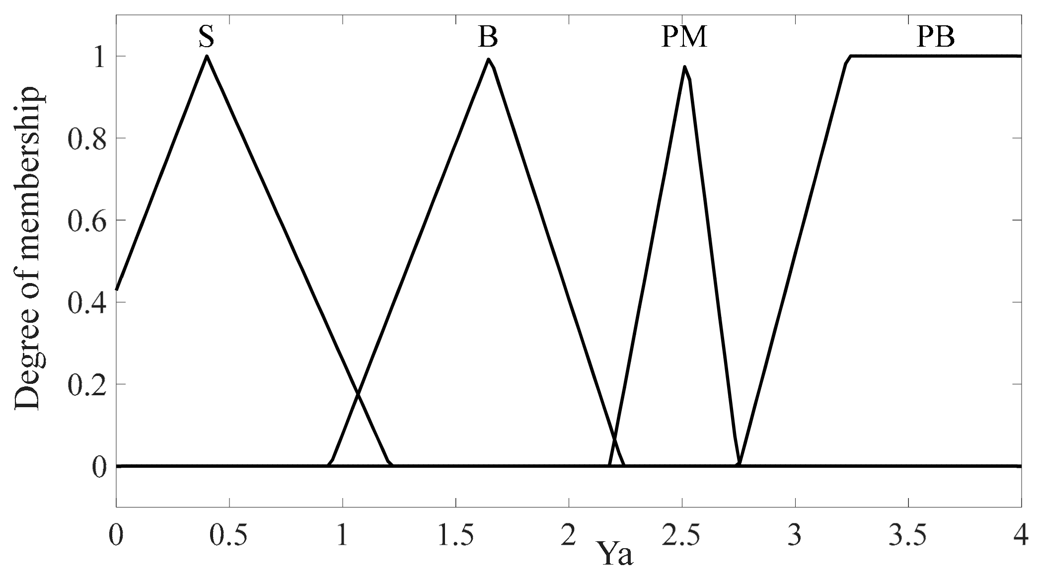
Figure 8.
Generated membership function for

Figure 9.
Generated membership function for

Figure 10.
Diagram of the parking strategy.

Figure 11.
Abscissa X time response diagram.

Figure 12.
Ordinate Y time response diagram.

Figure 13.
Course θ time response diagram.

Figure 14.
Speed V time response diagram.

Figure 15.
time response diagram.

Figure 16.
The trajectory of the fuzzy control parking to a different initial position.

Figure 17.
Trajectory of two different control methods.


Table 1.
Parameter of the membership function.
| Input | Output | |||||||
|---|---|---|---|---|---|---|---|---|
| Fuzzy Subset | S | Triangular | S | Triangular | N | Trapezoidal | NB | Triangular |
| [−0.23,0.20,0.57] | [−0.30,0.40,1.21] | [−44.6,−27.6,−17.6,−2.30] | [−35,−32.14,−29.15] | |||||
| B | Triangular | B | Triangular | Z | Triangular | NM | Triangular | |
| [0.40,0.70,1.00] | [0.94,1.65,2.24] | [−4.46,0,2.03] | [−29.77,−20.43,−11.09] | |||||
| P | Triangular | PM | Triangular | P | Trapezoidal | N | Triangular | |
| [0.93,1.47,1.92] | [2.18,2.52,2.75] | [0.11,7.37,56.3,91] | [−20.43,−11.71,−2.87] | |||||
| PB | Trapezoidal | PB | Trapezoidal | PM | Triangular | Z | Triangular | |
| [1.74,2.14,2.37,2.50] | [2.75,3.23,4.40,5.40] | [88,90,93.2] | [−3.85,0,4.12] | |||||
| PB | Trapezoidal | P | Triangular | |||||
| [92.45,97,120,120] | [2.87,11.71,20.43] | |||||||
| PM | Triangular | |||||||
| [4.98,14.95,24.91] | ||||||||
| PB | Trapezoidal | |||||||
| [23.67,26.16,37.37,37.37] | ||||||||
Table 2.
Fuzzy rules when is S.
| S | B | PM | PB | ||
|---|---|---|---|---|---|
| θ | |||||
| N | – | – | – | – | |
| Z | – | – | – | – | |
| P | NB | NB | – | – | |
| PM | Z | – | – | – | |
| PB | – | – | – | – | |
Table 3.
Fuzzy rules when is B.
| S | B | PM | PB | ||
|---|---|---|---|---|---|
| θ | |||||
| N | – | – | – | – | |
| Z | – | – | – | – | |
| P | – | NB | – | – | |
| PM | – | – | – | – | |
| PB | – | – | – | – | |
Table 4.
Fuzzy rules when is P.
| S | B | PM | PB | ||
|---|---|---|---|---|---|
| θ | |||||
| N | – | – | – | – | |
| Z | – | NB | – | – | |
| P | – | NB | – | – | |
| PM | – | – | – | – | |
| PB | – | – | – | – | |
Table 5.
Fuzzy rules when is P.
| S | B | PM | PB | ||
|---|---|---|---|---|---|
| θ | |||||
| N | – | NB | – | – | |
| Z | – | Z | – | – | |
| P | – | PB | – | – | |
| PM | – | – | – | – | |
| PB | – | – | – | – | |
© 2018 by the authors. Licensee MDPI, Basel, Switzerland. This article is an open access article distributed under the terms and conditions of the Creative Commons Attribution (CC BY) license (http://creativecommons.org/licenses/by/4.0/).
Share and Cite
MDPI and ACS Style
Xu, Y.; Lu, Z.; Shan, X.; Jia, W.; Wei, B.; Wang, Y. Study on an Automatic Parking Method Based on the Sliding Mode Variable Structure and Fuzzy Logical Control. Symmetry 2018, 10, 523. https://doi.org/10.3390/sym10100523
AMA Style
Xu Y, Lu Z, Shan X, Jia W, Wei B, Wang Y. Study on an Automatic Parking Method Based on the Sliding Mode Variable Structure and Fuzzy Logical Control. Symmetry. 2018; 10(10):523. https://doi.org/10.3390/sym10100523
Chicago/Turabian StyleXu, Ying, Zefeng Lu, Xin Shan, Wenhao Jia, Bo Wei, and Yingqing Wang. 2018. "Study on an Automatic Parking Method Based on the Sliding Mode Variable Structure and Fuzzy Logical Control" Symmetry 10, no. 10: 523. https://doi.org/10.3390/sym10100523
Note that from the first issue of 2016, this journal uses article numbers instead of page numbers. See further details here.