
Fabrication of Nano-Micro Hybrid Structures by Replication and Surface Treatment of Nanowires


Abstract
:1. Introduction
2. Aggregation of Nanowires
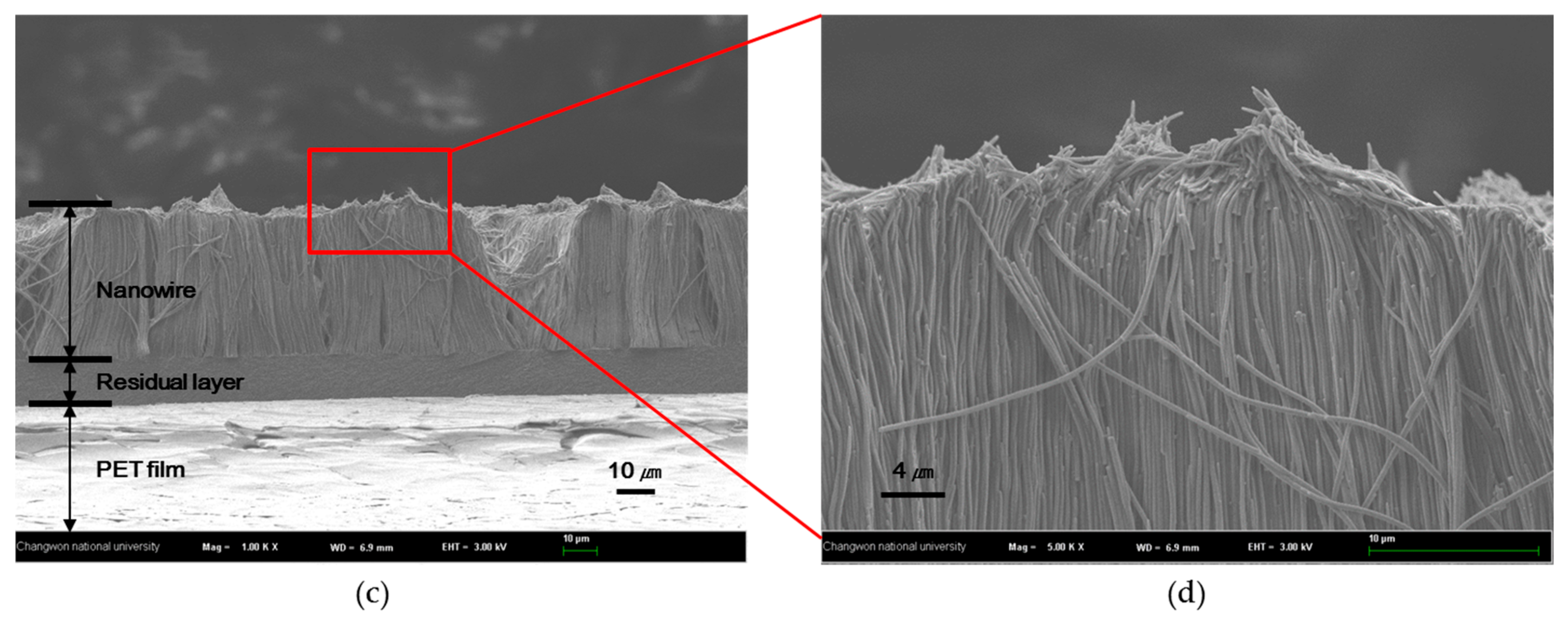
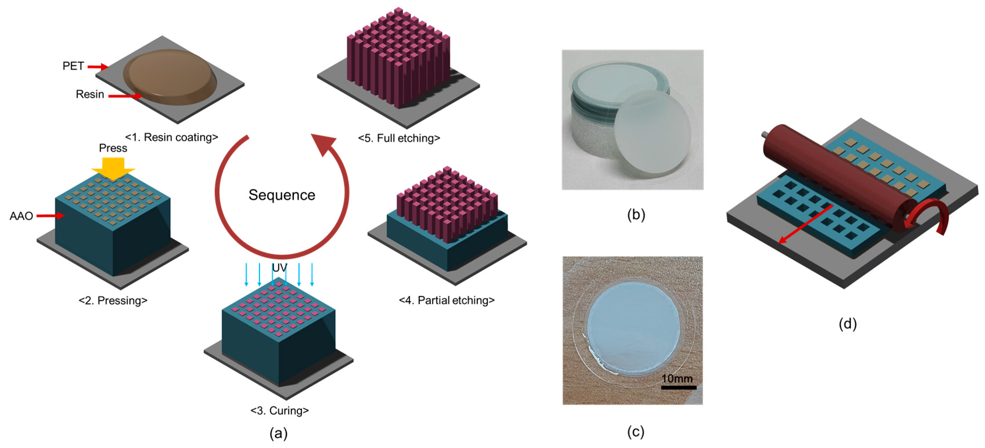
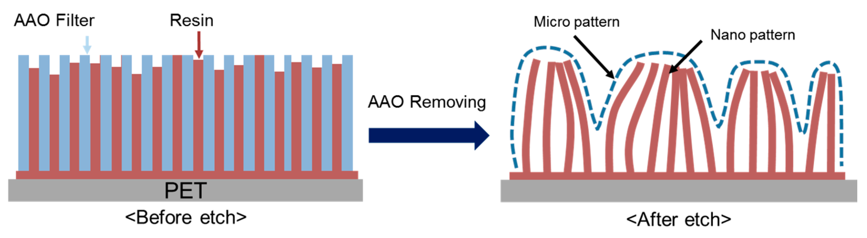
2.1. Fabrication of Nanowire Structure
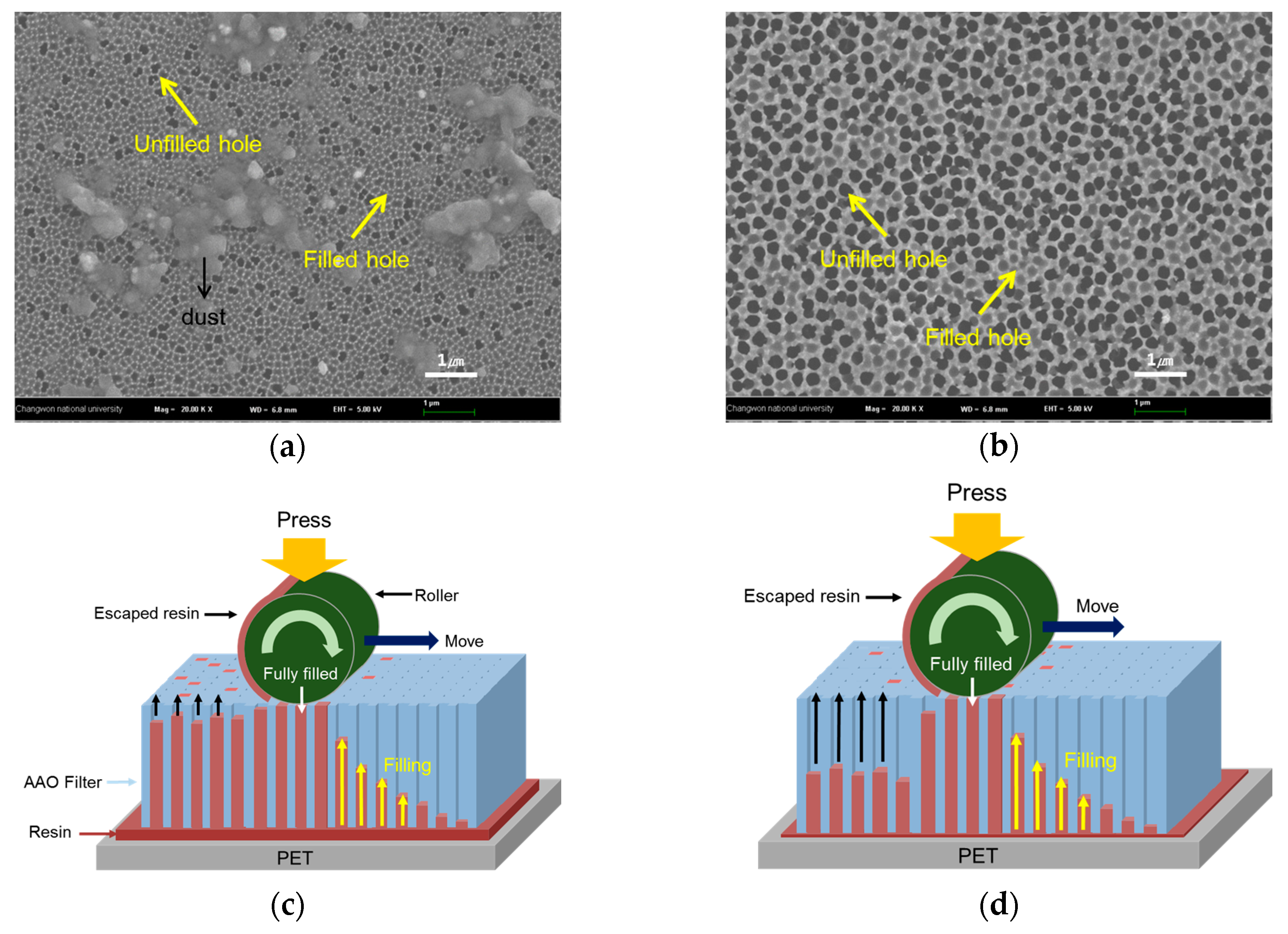
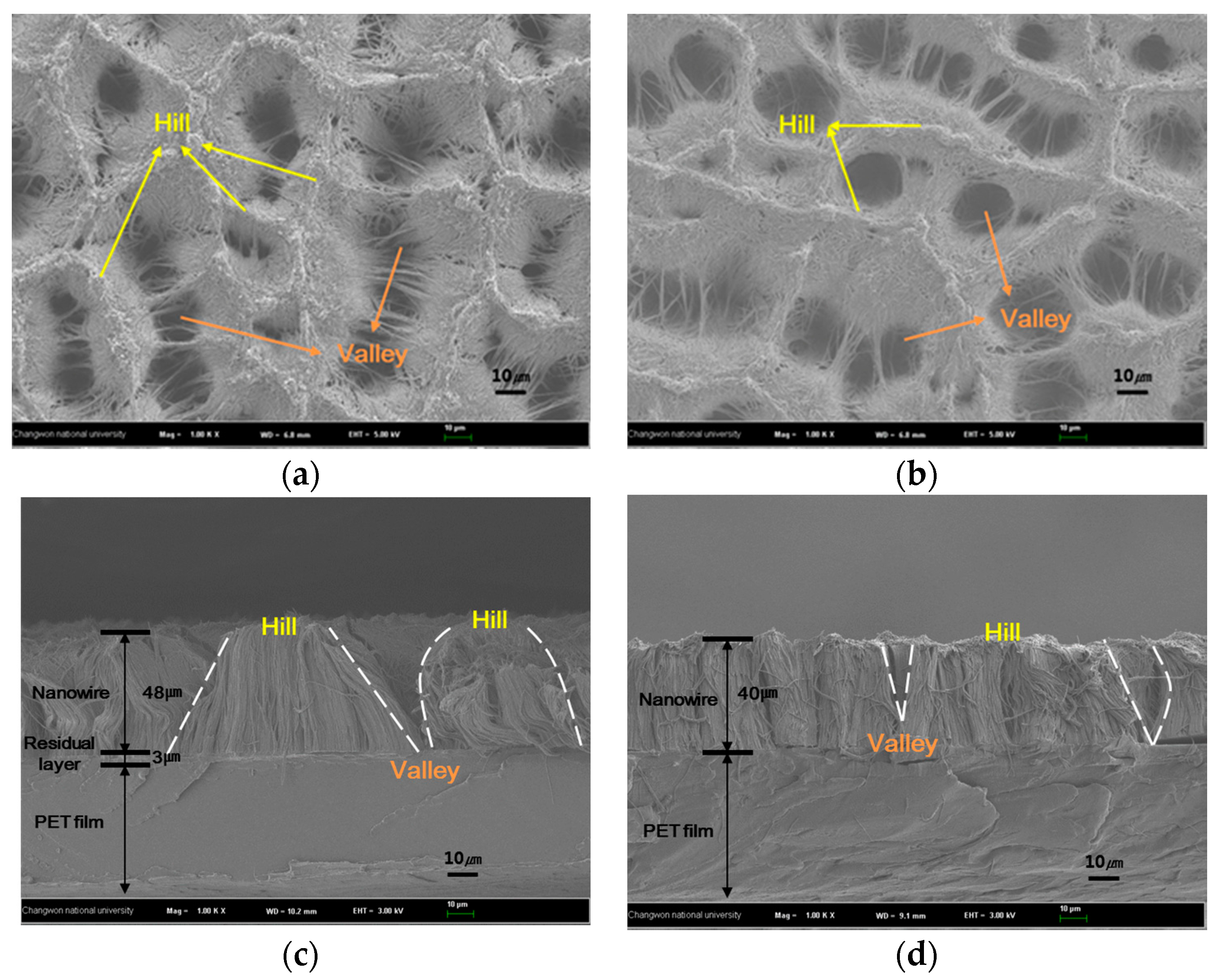
2.2. Changes in Nanowire Structure with Viscosity of Resin
3. Effect of Surface Treatment
3.1. Variation of Wettability with Surface Treatment
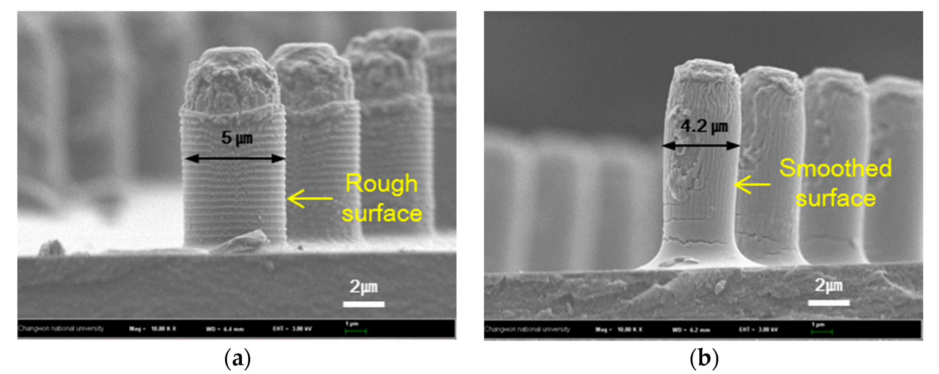
3.2. Structure Variation with Surface Treatments
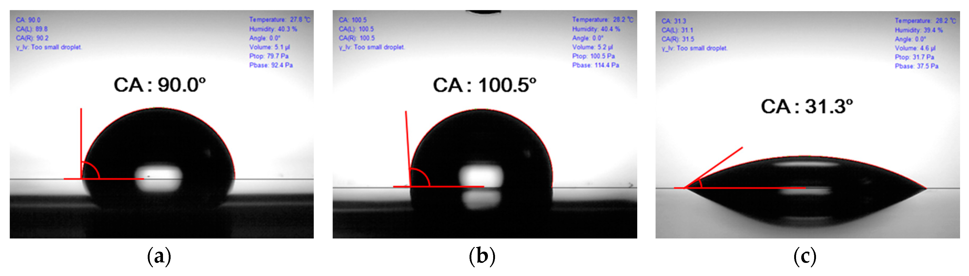
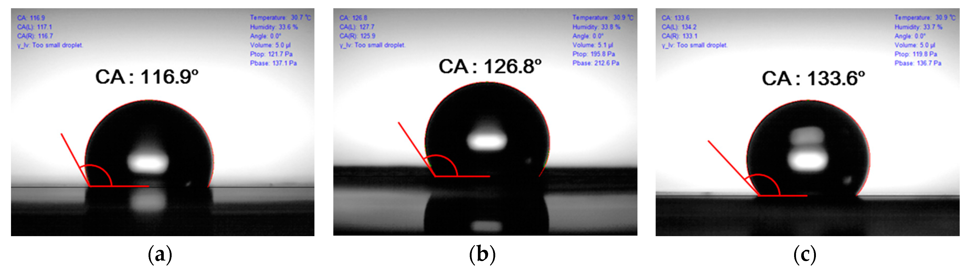
3.3. Contact Angle Variation with Surface Treatment
4. Conclusions
Acknowledgments
Author Contributions
Conflicts of Interest
References
- Elghanian, R.; Storhoff, J.J.; Mucic, R.C.; Letsinger, R.L.; Mirkin, C.A. Selective colorimetric detection of polynucleotides based on the distance-dependent optical properties of gold nanoparticles. Science 1997, 277, 1078–1081. [Google Scholar] [CrossRef] [PubMed]
- Berdichevsky, Y.; Lo, Y.H. Polypyrrole nanowire actuators. Adv. Mater. 2016, 18, 122–125. [Google Scholar] [CrossRef]
- Mitchell, D.T.; Lee, S.B.; Trofin, L.; Li, N.; Nevanen, T.K.; Söderlund, H.; Martin, C.R. Smart nanotubes for bioseparations and biocatalysis. J. Am. Chem. Soc. 2002, 124, 11864–11865. [Google Scholar] [CrossRef] [PubMed]
- Nicewarner-Pena, S.R.; Freeman, R.G.; Reiss, B.D.; He, L.; Peña, D.J.; Walton, I.D.; Cromer, R.; Keating, C.D.; Natan, M.J. Submicrometer metallic barcodes. Science 2001, 294, 137–141. [Google Scholar] [CrossRef] [PubMed]
- Dersch, R.; Steinhart, M.; Boudriot, U.; Greiner, A.; Wendorff, J.H. Nanoprocessing of polymers: Applications in medicine, sensors, catalysis, photonics. Polym. Adv. Technol. 2005, 16, 276–282. [Google Scholar] [CrossRef]
- Baker, L.A.; Jin, P.; Martin, C.R. Biomaterials and biotechnologies based on nanotube membranes. Crit. Rev. Solid State Mater. Sci. 2005, 30, 183–205. [Google Scholar] [CrossRef]
- Xiang, H.; Shin, K.; Kim, T.; Moon, S.I.; McCarthy, T.J.; Russell, T.P. Block copolymers under cylindrical confinement. Macromolecules 2004, 37, 5660–5664. [Google Scholar] [CrossRef]
- Fei, G.; Tuinea-Bobe, C.; Li, D.; Li, G.; Whiteside, B.; Coates, P.; Xia, H. Electro-activated surface micropattern tuning for microinjection molded electrically conductive shape memory polyurethane composites. RSC Adv. 2013, 3, 24132–24139. [Google Scholar] [CrossRef]
- Kim, K.; Kim, J.; Hyun, B.G.; Ji, S.; Kim, S.Y.; Kim, S.W.; An, B.W.; Park, J.U. Stretchable and transparent electrodes based on in-plane structures. Nanoscale 2015, 7, 14577–14594. [Google Scholar] [CrossRef] [PubMed]
- Kim, J.; Kim, M.; Lee, M.S.; Kim, K.; Ji, S.; Kim, Y.T.; Park, J.H.; Na, K.M.; Bae, K.H.; Kim, H.K.; et al. Wearable smart sensor systems integrated on soft contact lenses for wireless ocular diagnostics. Nat. Commun. 2017, 8, 14997. [Google Scholar] [CrossRef] [PubMed]
- Park, J.; Kim, J.; Kim, K.; Kim, S.Y.; Cheong, W.H.; Park, K.; Song, J.H.; Namgoong, G.; Kim, J.J.; Heo, J.; et al. Wearable, wireless gas sensors using highly stretchable and transparent structures of nanowires and graphene. Nanoscale 2016, 8, 10591–10597. [Google Scholar] [CrossRef] [PubMed]
- An, B.W.; Kim, K.; Lee, H.; Kim, S.Y.; Shim, Y.; Lee, D.Y.; Song, J.Y.; Park, J.U. High-resolution printing of 3D structures using an electrohydrodynamic inkjet with multiple functional inks. Adv. Mater. 2015, 27, 4322–4328. [Google Scholar] [CrossRef] [PubMed]
- Kim, M.; Park, J.; Ji, S.; Shin, S.H.; Kim, S.Y.; Kim, Y.C.; Kim, J.Y.; Park, J.U. Fully-integrated, bezel-less transistor arrays using reversibly foldable interconnects and stretchable origami substrates. Nanoscale 2016, 8, 9504–9510. [Google Scholar] [CrossRef] [PubMed]
- Zhao, Y.S.; Zhan, P.; Kim, J.; Sun, C.; Huang, J. Patterned growth of vertically aligned organic nanowire waveguide arrays. ACS Nano 2010, 4, 1630–1636. [Google Scholar] [CrossRef] [PubMed]
- Kuo, C.W.; Shiu, J.Y.; Chen, P. Size-and shape-controlled fabrication of large-area periodic nanopillar arrays. Chem. Mater. 2003, 15, 2917–2920. [Google Scholar] [CrossRef]
- Lee, S.B.; Koepsel, R.; Stolz, D.B.; Warriner, H.E.; Russell, A.J. Self-assembly of biocidal nanotubes from a single-chain diacetylene amine salt. J. Am. Chem. Soc. 2004, 126, 13400–13405. [Google Scholar] [CrossRef] [PubMed]
- Gibson, J.M. Reading and writing with electron beams. Phys. Today 1997, 50, 56–61. [Google Scholar] [CrossRef]
- Kramer, N.; Birk, H.; Jorritsma, J.; Schönenberger, C. Fabrication of metallic nanowires with a scanning tunneling microscope. Appl. Phys. Lett. 1995, 66, 1325–1327. [Google Scholar] [CrossRef]
- Jiang, P.; Bertone, J.F.; Colvin, V.L. A lost-wax approach to monodisperse colloids and their crystals. Science 2001, 291, 453–457. [Google Scholar] [CrossRef] [PubMed]
- Steinhart, M.; Wendorff, J.H.; Greiner, A.; Wehrspohn, R.B.; Nielsch, K.; Schilling, J.; Choi, J.; Gösele, U. Polymer nanotubes by wetting of ordered porous templates. Science 2002, 296, 1997. [Google Scholar] [CrossRef] [PubMed]
- Hong, S.H.; Hwang, J.; Lee, H. Replication of cicada wing’s nano-patterns by hot embossing and UV nanoimprinting. Nanotechnology 2009, 20, 385303. [Google Scholar] [CrossRef] [PubMed]
- Han, K.S.; Shin, J.H.; Yoon, W.Y.; Lee, H. Enhanced performance of solar cells with anti-reflection layer fabricated by nano-imprint lithography. Sol. Energy Mater. Sol. Cells 2011, 95, 288–291. [Google Scholar] [CrossRef]
- Choo, S.; Choi, H.J.; Lee, H. Replication of rose-petal surface structure using UV-nanoimprint lithography. Mater. Lett. 2014, 121, 170–173. [Google Scholar] [CrossRef]
- Yu, Z.; Chou, S.Y. Triangular profile imprint molds in nanograting fabrication. Nano Lett. 2004, 4, 341–344. [Google Scholar] [CrossRef]
- Hirai, Y.; Harara, S.; Isaka, S.; Kobayashi, M.; Tanaka, Y. Nano-Imprint lithography using replicated mold by Ni electroforming. Jpn. J. Appl. Phys. 2002, 41, 4186. [Google Scholar] [CrossRef]
- Kim, J.H.; Cho, Y.T.; Jung, Y.G. Selection of absorptive materials for non-reflective wire grid polarizers. Int. J. Precis. Eng. Manuf. 2016, 17, 903–908. [Google Scholar] [CrossRef]
- Stępniowski, W.J.; Salerno, M. Fabrication of nanowires and nanotubes by anodic alumina template-assisted electrodeposition. Manuf. Nanostruct. 2014, 12, 321–357. [Google Scholar]
- Sousa, C.T.; Leitao, D.C.; Proenca, M.P.; Ventura, J.; Pereira, A.M.; Araujo, J.P. Nanoporous alumina as templates for multifunctional applications. Appl. Phys. Rev. 2014, 1, 031102. [Google Scholar] [CrossRef]
- Hong, S.H.; Bae, B.J.; Lee, H.; Jeong, J.H. Fabrication of high density nano-pillar type phase change memory devices using flexible AAO shaped template. Microelectron. Eng. 2010, 87, 2081–2084. [Google Scholar] [CrossRef]
- Schwirn, K.; Lee, W.; Hillebrand, R.; Steinhart, M.; Nielsch, K.; Gösele, U. Self-ordered anodic aluminum oxide formed by H2SO4 hard anodization. ACS Nano 2008, 2, 302–310. [Google Scholar] [CrossRef] [PubMed]
- Lee, P.S.; Lee, O.J.; Hwang, S.K.; Jung, S.H.; Jee, S.E.; Lee, K.H. Vertically aligned nanopillar arrays with hard skins using anodic aluminum oxide for nano imprint lithography. Chem. Mater. 2005, 17, 6181–6185. [Google Scholar] [CrossRef]
- Lopes, M.C.; de Oliveira, C.P.; Pereira, E.C. Computational modeling of the template-assisted deposition of nanowires. Electrochim. Acta 2008, 53, 4359–4369. [Google Scholar] [CrossRef]
- Choi, M.K.; Yoon, H.; Lee, K.; Shin, K. Simple fabrication of asymmetric high-aspect-ratio polymer nanopillars by reusable AAO templates. Langmuir 2011, 27, 2132–2137. [Google Scholar] [CrossRef] [PubMed]
- Kim, Y.S.; Lee, K.; Lee, J.S.; Jung, G.Y.; Kim, W.B. Nanoimprint lithography patterns with a vertically aligned nanoscale tubular carbon structure. Nanotechnology 2008, 19, 365305. [Google Scholar] [CrossRef] [PubMed]
- Chen, G.; Soper, S.A.; McCarley, R.L. Free-standing, erect ultrahigh-aspect-ratio polymer nanopillar and nanotube ensembles. Langmuir 2007, 23, 11777–11781. [Google Scholar] [CrossRef] [PubMed]
- Choi, W.K.; Kim, S.H.; Choi, S.G.; Lee, E.S.; Lee, C.H. Effect of pad’s surface deformation and oscillation on monocrystalline silicon wafer surface quality. Int. J. Precis. Eng. Manuf. 2014, 15, 2301–2307. [Google Scholar] [CrossRef]
- Schonhorn, H.; Hansen, R.H. Surface treatment of polymers for adhesive bonding. J. Appl. Polym. Sci. 1967, 11, 1461–1474. [Google Scholar] [CrossRef]
- Liang, Y.; Zhen, C.; Zou, D.; Xu, D. Preparation of free-standing nanowire arrays on conductive substrates. J. Am. Chem. Soc. 2004, 126, 16338–16339. [Google Scholar] [CrossRef] [PubMed]
- Hu, G.; Zhang, H.; Di, W.; Zhao, T. Study on wet etching of AAO template. Appl. Phys. Res. 2009, 1, 78–82. [Google Scholar] [CrossRef]
- Song, G.; Chen, D.; Peng, Z.; She, X.; Li, J.; Han, P. Quantificational etching of AAO template. J. Mater. Sci. Technol. Shenyang 2007, 23, 427. [Google Scholar]
- Murphy, A.; McPhillips, J.; Hendren, W.; McClatchey, C.; Atkinson, R.; Wurtz, G.; Zayats, A.V.; Pollard, R.J. The controlled fabrication and geometry tunable optics of gold nanotube arrays. Nanotechnology 2010, 22, 045705. [Google Scholar] [CrossRef] [PubMed]
- Gu, D.; Baumgart, H.; Abdel-Fattah, T.M.; Namkoong, G. Synthesis of nested coaxial multiple-walled nanotubes by atomic layer deposition. ACS Nano 2010, 4, 753–758. [Google Scholar] [CrossRef] [PubMed]
- Chu, C.W.; Huang, Y.C.; Tsai, C.C.; Chen, J.T. Wetting in nanopores of cylindrical anodic aluminum oxide templates: Production of gradient polymer nanorod arrays on large-area curved surfaces. Eur. Polym. J. 2015, 63, 141–148. [Google Scholar] [CrossRef]
- Lim, S.C.; Kim, S.H.; Lee, J.H.; Kim, M.K.; Zyung, T. Surface-treatment effects on organic thin-film transistors. Synth. Met. 2005, 148, 75–79. [Google Scholar] [CrossRef]
- Gongjian, B.; Yunxuan, W.; Xingzhou, H. Surface modification of polyolefine by UV light/ozone treatment. J. Appl. Polym. Sci. 1996, 60, 2397–2402. [Google Scholar] [CrossRef]
- Maoz, R.; Matlis, S.; DiMasi, E.; Ocko, B.M.; Sagiv, J. Self-replicating amphiphilic monolayers. Nature 1996, 384, 150. [Google Scholar] [CrossRef]
- Nie, H.Y.; Walzak, M.J.; Berno, B.; McIntyre, N.S. Atomic force microscopy study of polypropylene surfaces treated by UV and ozone exposure: Modification of morphology and adhesion force. Appl. Surf. Sci. 1999, 144, 627–632. [Google Scholar] [CrossRef]
- Efimenko, K.; Wallace, W.E.; Genzer, J. Surface modification of Sylgard-184 poly (dimethyl siloxane) networks by ultraviolet and ultraviolet/ozone treatment. J. Colloid Interface Sci. 2002, 254, 306–315. [Google Scholar] [CrossRef] [PubMed]
- Vidal-Iglesias, F.J.; Solla-Gullón, J.; Herrero, E.; Montiel, V.; Aldaz, A.; Feliu, J.M. Evaluating the ozone cleaning treatment in shape-controlled Pt nanoparticles: Evidences of atomic surface disordering. Electrochem. Commun. 2001, 13, 502–505. [Google Scholar] [CrossRef]


| Viscosity of PUA Resins | Thickness of Nanowire Layer | Note |
|---|---|---|
| 257.4 cPs | 48 ± 4 µm | The resin with 257.4 cPs viscosity was well filled into AAO filter because of difference of cohesion force |
| 7.2 cPs | 40 ± 5 µm |
| Surface Treatment | Contact Angle | Structure (The Size of Dimples) | Note |
|---|---|---|---|
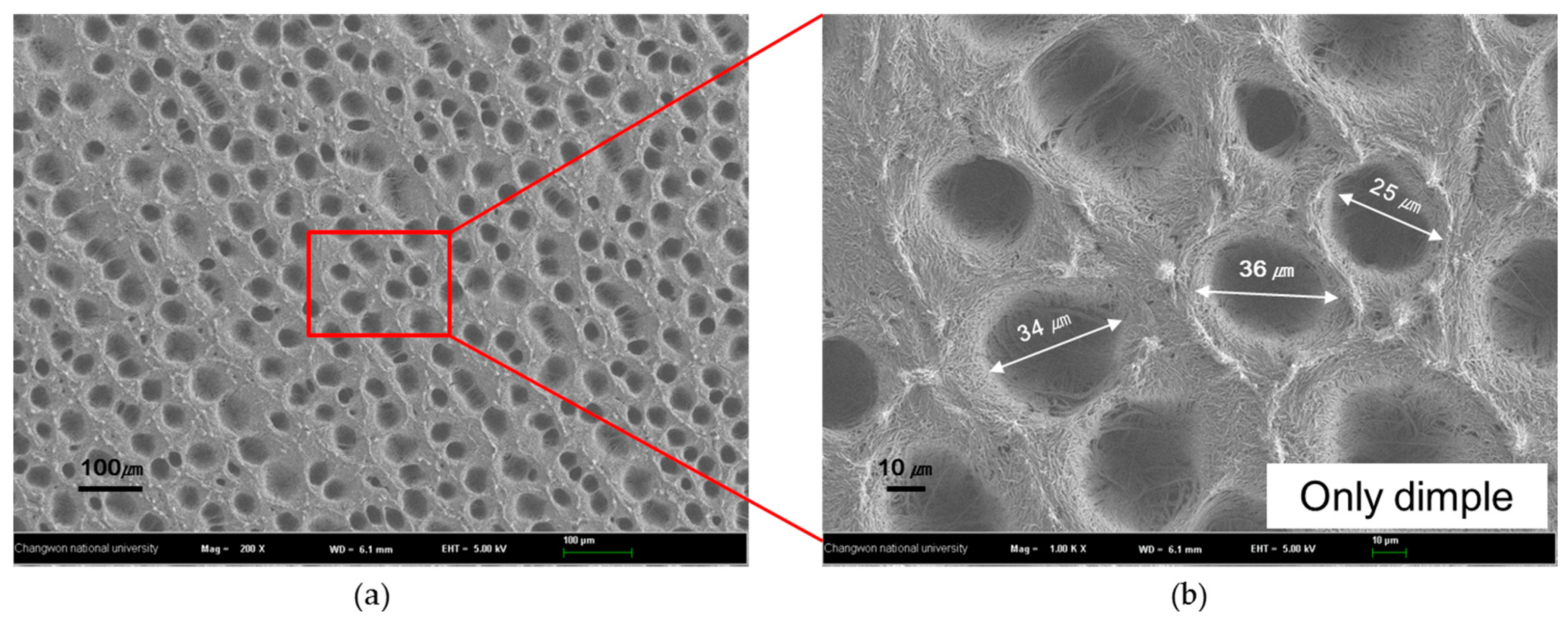
| No treatment | Super hydrophilic | 30 ± 5 µm | The nano-micro hybrid structure because of the aggregated nanowires was obtained |
| Silane monolayer treatment | 117 ± 2° | Similar to that for no treatment | The hydrophobic surface was fabricated because silane monolayer was coated |
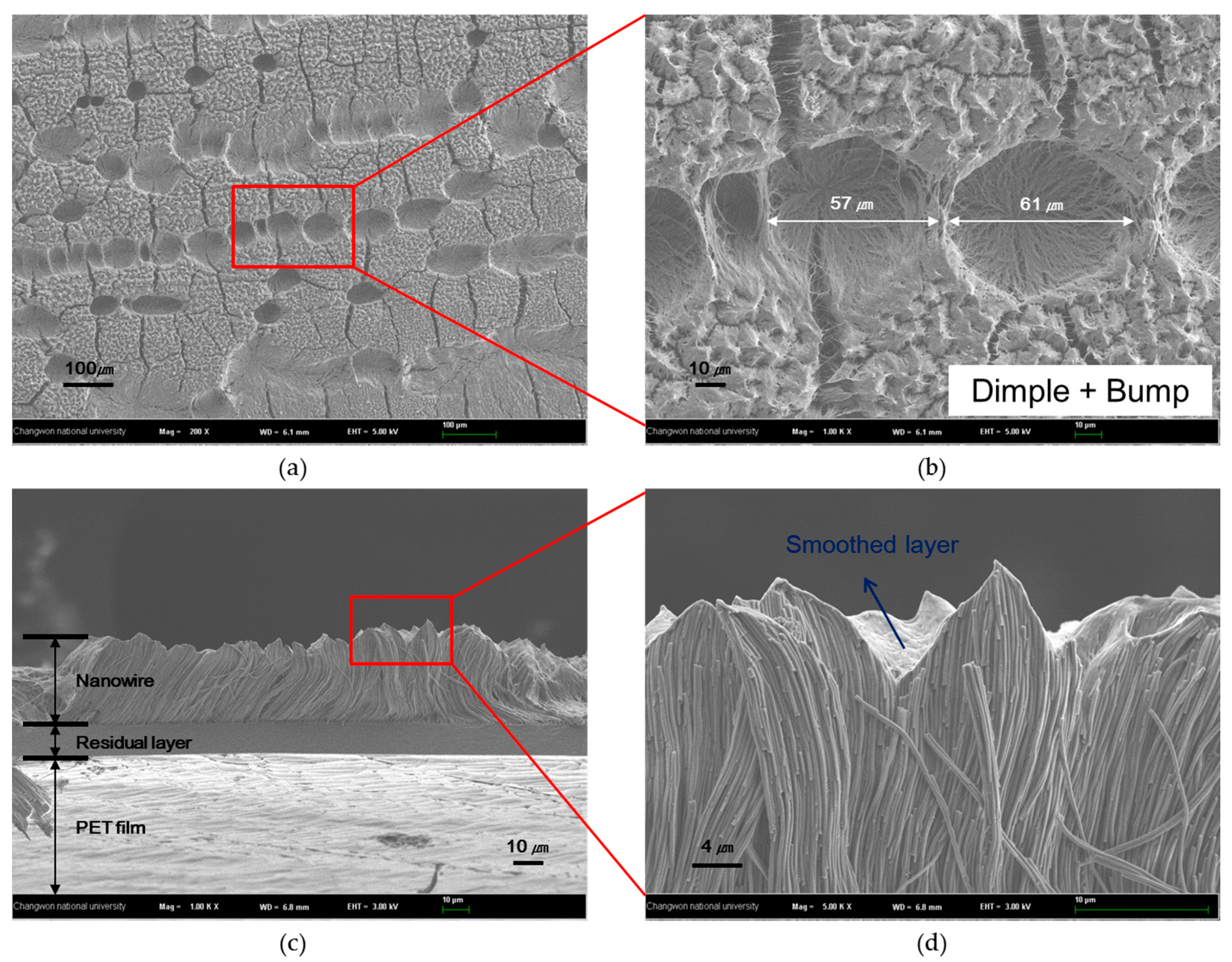
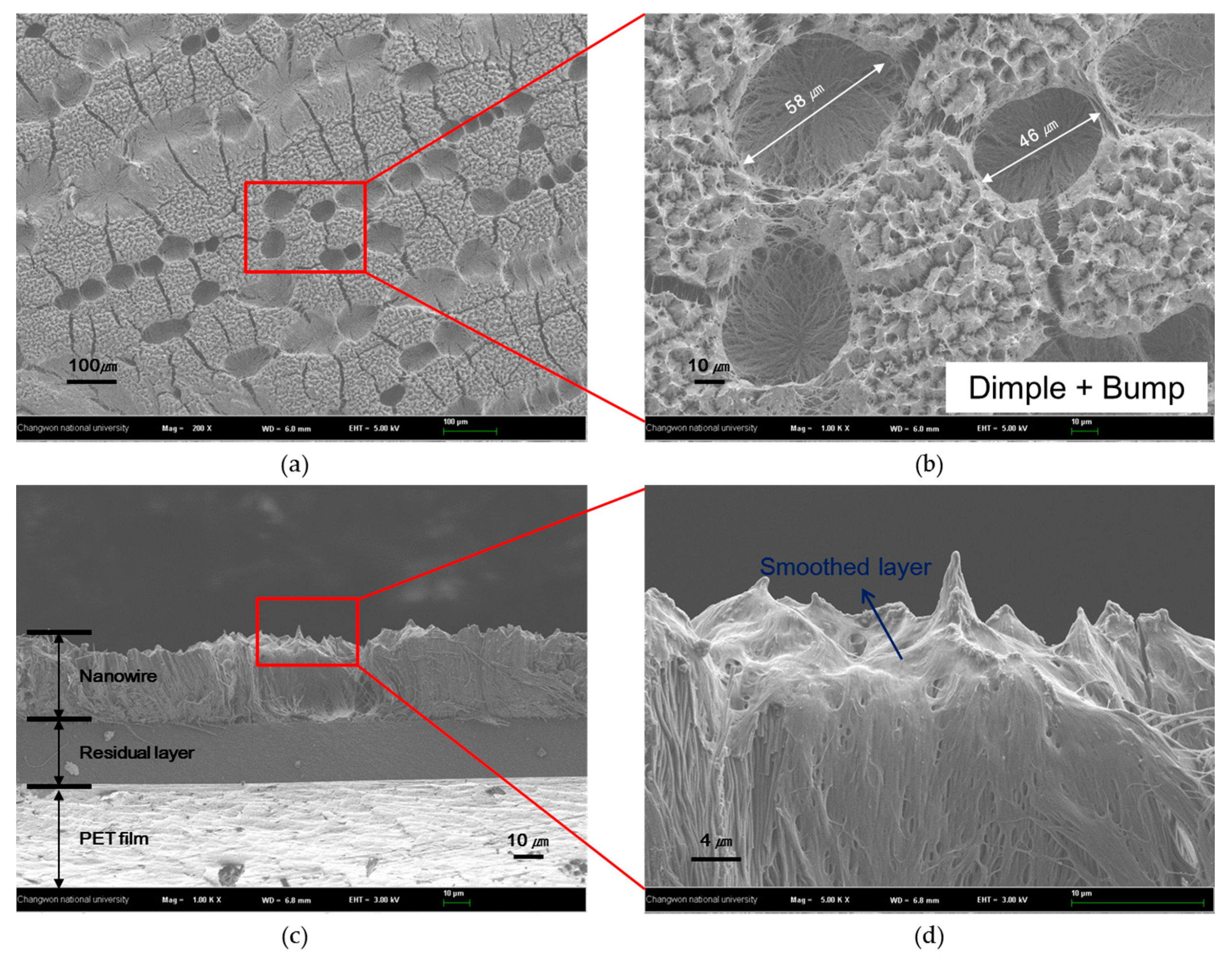
| UV-ozone treatment | 127 ± 3° | 60 ± 10 µm | The contact angle increased because of smoothed layer |
| Double treatment | 134 ± 2° | Similar to that for UV-ozone treatment | The contact angle was higher according to the silane monolayer |
© 2017 by the authors. Licensee MDPI, Basel, Switzerland. This article is an open access article distributed under the terms and conditions of the Creative Commons Attribution (CC BY) license (http://creativecommons.org/licenses/by/4.0/).
Share and Cite
Jeong, Y.; Shin, S.; Choi, H.; Kim, S.; Kim, J.; Kwon, S.; Kim, K.-Y.; Lee, S.-H.; Jung, Y.-G.; Cho, Y.T. Fabrication of Nano-Micro Hybrid Structures by Replication and Surface Treatment of Nanowires. Crystals 2017, 7, 215. https://doi.org/10.3390/cryst7070215
Jeong Y, Shin S, Choi H, Kim S, Kim J, Kwon S, Kim K-Y, Lee S-H, Jung Y-G, Cho YT. Fabrication of Nano-Micro Hybrid Structures by Replication and Surface Treatment of Nanowires. Crystals. 2017; 7(7):215. https://doi.org/10.3390/cryst7070215
Chicago/Turabian StyleJeong, Yeonho, Seunghang Shin, Hyunmin Choi, Seonjun Kim, Jihoon Kim, Sin Kwon, Kwang-Young Kim, Seung-Hyun Lee, Yoon-Gyo Jung, and Young Tae Cho. 2017. "Fabrication of Nano-Micro Hybrid Structures by Replication and Surface Treatment of Nanowires" Crystals 7, no. 7: 215. https://doi.org/10.3390/cryst7070215