Article

Silica-Metal Composite for Hydrogen Storage Applications

1
Casaccia Research Centre, ENEA–Italian National Agency for New Technologies, Energy and Sustainable Economic Development, Via Anguillarese 301, 00123, Rome, Italy
2
Labor S.r.l. Industrial Research Laboratory, Via Giacomo Peroni 386, Rome, Italy
*
Author to whom correspondence should be addressed.
Crystals 2012, 2(2), 690-703; https://doi.org/10.3390/cryst2020690
Submission received: 2 February 2012 / Revised: 23 May 2012 / Accepted: 6 June 2012 / Published: 18 June 2012
(This article belongs to the Special Issue Hydrogen Storage Alloys)

Abstract

:
In spite of their favourable chemical characteristics, using AB5 alloys as fixed bed for hydrogen storage devices requires proper management of a number of technological aspects. Among these, the mechanical stability of metal particle grains under hydrogen cycling and the overall thermal conductivity of the material bed constitute crucial features. We developed by High Energy Ball Milling HEBM a mechanically stable silica-based AB5 composite with enhanced thermal conductivity. Here, focusing on the material’s physical-chemical properties, we report on the silica-AB5 composite development and characterization. Particularly, we studied the material consolidation process, the resulting composite morphology and the system behaviour under hydrogen loading/unloading cycling.

1. Introduction

Hydrogen is a combustible gas that can play a strategic role in the development of the future sustainable world. When available, renewable energy can be utilized to produce hydrogen and the gas storage permits its successive utilization to produce energy when any sustainable source is accessible. Easy and safe storage of hydrogen can be obtained by reversible chemisorption into alloys to form hydride compounds. Storage and recovery of hydrogen into and from metal hydrides will permit to overcome the discontinuous characteristic of renewable energetic supplies and will allow the possibility to conceive a CO2-emission free new energetic paradigm. Thus, hydrogen storage in metal alloys constitutes an affordable solution in developing and managing a fully sustainable energetic system.
Several intermetallic systems can be utilized in hydriding reactions. Among these, the AB5 systems, such as LaNi5-based alloys are today considered the strongest ones in particular for stationary applications. In fact, even if the maximum amount of the incorporated hydrogen does not exceed values around 1.5% weight, the large volumetric density of the stored hydrogen, the chemical stability of the metal compound and the hydrogen pressure at room temperature make this class of materials an attractive solution for safe hydrogen storage.
In spite of the favourable chemical characteristics exhibited by the AB5 alloys, their use as fixed bed in a hydrogen storage device requires further improvements of some other properties. Among these, the mechanical stability of metal particle grains under hydrogen cycling and the overall thermal conductivity of the active material bed are crucial technological aspects. In fact, the large molar volumes variation exhibited by the H2 loaded and unloaded phases [1,2] produces a relevant metal particle pulverization phenomenon. The main detrimental effects due to decrepitating particles consist in impediment to hydrogen diffusion, alloy loss by entrapment of tiny particles in device accessories, increase of alloy deterioration by the feed gas impurities and rapid plugging of dust filters. This represents a serious obstacle limiting the efficiency of the hydride-based storage device. Different approaches to prevent pulverization phenomena by encapsulating the alloy particles within various media (copper, phenolic resins and polymers) have been proposed [3,4,5,6,7]. In particular, the use of a porous silica or polymeric matrix appears a reliable solution [8,9,10,11,12].
We previously demonstrated that the solid-state HEBM technique [13] could be successfully used to develop a mechanically stable silica-based composite possessing enhanced thermal conductivity by embedding metal and graphite particles in a porous silica matrix [12].
In this paper, we report on silica-based composite development and characterization, focusing on the material physical-chemical properties. By developing a simplified system that does not contain the graphite filler minor component, we studied the silica-metal consolidation process, the resulting composite morphology, and the system behaviour under hydrogen loading/unloading cycling.

2. Materials and Methods

2.1. Composite Preparation

The preparation of the silica-AB5 composite material was carried out via the following actions: (i) mechanical pulverization of the AB5 hydriding alloy; (ii) preparation of the silica-AB5 blends by thorough mixing of the powders by a second milling treatment, and (iii) blend consolidation by cold uniaxial compression and successive thermal treatment.
The selected active metal was an AB5 alloy, derived from the intermetallic compound LaNi5, specifically the Hy-Stor 208 by Ergenics. The nominal composition of the alloy (henceforth referred to as LaNi5) is MmNi4.5Al0.5, where Mm stands for a Misch-Metal. Chemical analysis conducted on the mixture of lanthanides gave the following composition: Lanthanum ~34%, Cerium ~49%, Neodymium ~13% and Praseodymium ~4%. This alloy was chosen due to its stability under hydrogenation/dehydrogenation cycles. Moreover, its resistance to oxidation phenomena, which has been verified up to 130 °C, permitted easy handling of the material through the ball milling process treatments. The LaNi5 fresh samples were mechanically treated to breakdown the metal particles into powder, of 10–100 μm diameter. The milling was conducted by means of a high energetic mill, the SPEX 8000 M. The stainless steel vials were filled with LaNi5 together with stainless steel balls (Ø 8 mm). The vial volume was 60 cm3, the metal to balls weight ratio was 1 to 10. Under these conditions the LaNi5 was milled for 15 min under vacuum.
The pyrogenic silica T30 (henceforth referred as SiO2), supplied by the Wacker Chemie AG, was used as embedding matrix. The SiO2 nominal surface area was 300m2/g. The fresh SiO2 samples were vacuum milled in order to promote an easy handling of highly dispersed powder (SPEX 8000M apparatus, 8 mm balls diameter, material: balls weight ratio of 1:10, 2 min milling time).
The metal-silica (henceforth referred as LaNi5-SiO2) blend was obtained by mixing previously treated metal powder and pyrogenic silica in a 40:60 volume ratio, corresponding to 70:30 weight ratio. The mixture was mechanically treated (SPEX 8000M apparatus, 5 mm balls diameter, material:balls weight ratio of 1:10, 15 min milling time). For comparative purposes a pure SiO2 sample was treated under identical conditions.
The milled LaNi5-SiO2 powder mixture was shaped into cylindrical pellets of 10 mm diameter by means of a uniaxial hydraulic press. The powder samples were inserted in a die-set equipped with a vacuum outlet. The powder was consolidated through step-by-step increasing of the applied pressure up to about 2.5 tons/cm2. The consolidation was carried out at room temperature while removing the die-set to minimize the residual air content and to obtain compact pellets of about 5 mm height.
A consolidated SiO2 comparative pellet sample was obtained by an identical treatment sequence. It is worth noting that the silica ball milling pre-treatment was crucial to allow the consolidation in pellets (non pre-treated samples presented a number of fractures along the direction orthogonal to the pressure axis).
After selecting the appropriate temperature by thermal gravimetric analysis (TGA) as reported in the following, both the SiO2 and LaNi5-SiO2 pellet samples were thermally treated (2 h) under argon atmosphere.

2.2. Characterization Techniques

Microstructural characterization of the samples was performed by X-ray Diffraction (XRD), using a Seifert-PAD VI diffractometer equipped with Mo Kα radiation and a LiF monochromator on the diffracted beam.
The TGA was performed using a Perkin-Elmer Pyris Diamond apparatus. Measurements were carried out under argon atmosphere at 5 °C/min heating rate.
The morphology of the LaNi5-SiO2 blend samples were studied by Scanning Electron Microscopy (SEM) analyses performed using a high resolution FE-SEM LEO 1530 instrument.
Nitrogen adsorption isotherms at 77 K were measured on the powder and consolidated samples by using a Quantachrome Nova 2200e volumetric device. The Brunauer-Emmet-Teller, BET [14], the Dubinin-Raducekevic, DR [15], and α-plot [16] methods were applied to the collected data.
Thermal Programmed Desorption (TPD) measurements were performed in a Micromeritics TPD/TPR apparatus, operating in H2 (3% vol)/Argon flux (40 mL/min).
Thermal characteristics of the hydrogenation/dehydrogenation processes were determined by the High Pressure Differential Scanning Calorimetry (HP-DSC) technique using a Perkin Elmer DSC7 apparatus (10 °C/min heating rate; 10–150 °C temperature range). By using the High Pressure accessory the DSC measurements were performed at constant hydrogen pressure (10 bar).

3. Results and Discussion

3.1. Material Processing

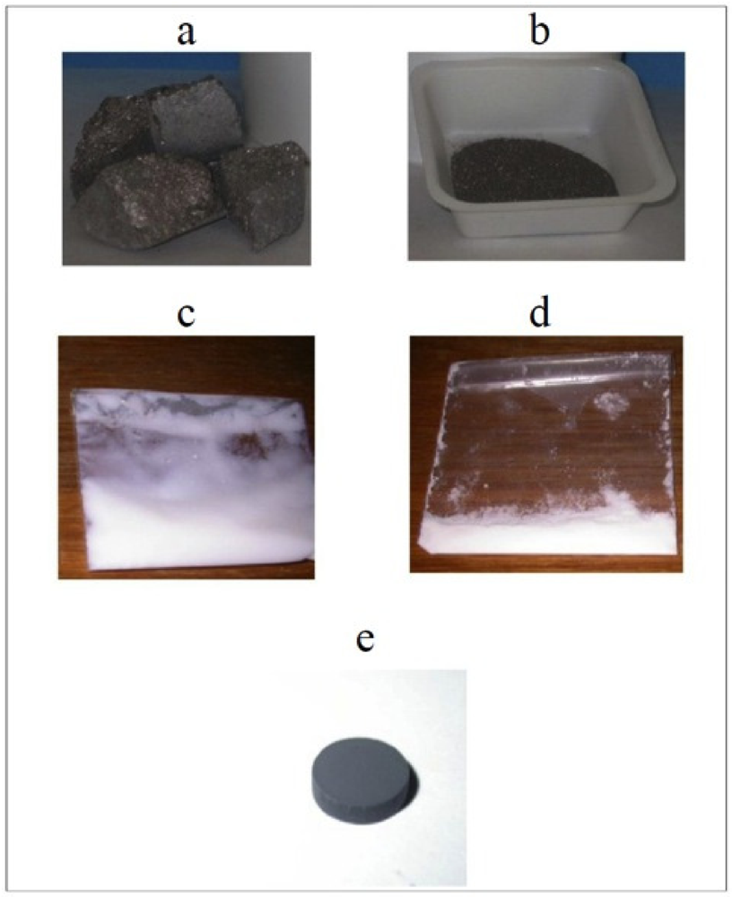
In Figure 1, a view of the starting and processed materials is shown.
Figure 1. A view of the starting and processed materials. Intermetallic alloy: (a) after cast; (b) after 15 min HEBM processing. Pyrogenic silica; (c) as received; (d) after HEBM processing; (e) Consolidated composite sample.
Crystals 02 00690 g001
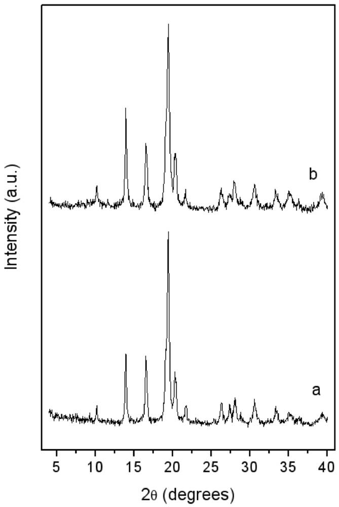
In Figure 2, the XRD patterns of the LaNi5 before and after 15 min blending with pyrogenic silica are reported. In both, only the patterns of the features of the metal phase are evident. An evaluation of crystallite size—as performed by the Sherrer law—on the (101) isolated peak gave about 20 nm for both the unblended and blended alloys. The blending by milling process did not promote the formation of any new phase. The applied milling conditions, in particular the low milling time (2 min), prevented the occurrence of unwanted mechanochemical effects [17], so that silica just acts as an inert dispersion media.
Figure 2. X-ray Diffraction (XRD) patterns of: (a) LaNi5 powder after 15 min high energy ball milling under vacuum; (b) LaNi5-SiO2 blend after 15 min milling.
Crystals 02 00690 g002
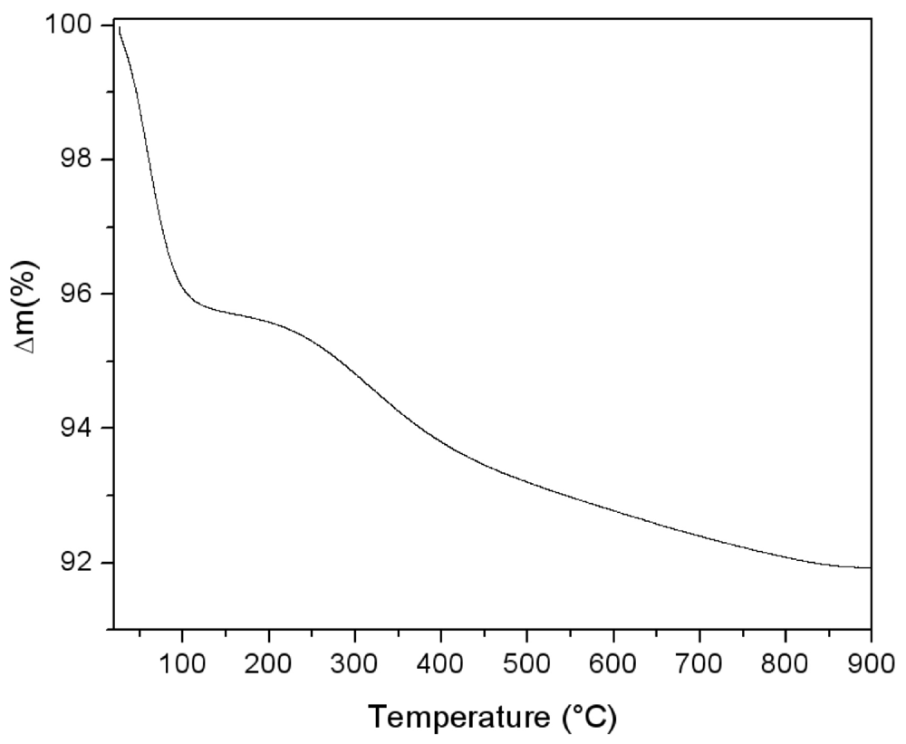
The thermal behaviour of the silica powder was followed by TGA analysis in order to study the particle reticulation by condensation of surface silanol groups. In Figure 3, the obtained thermogravimetric curve is reported. The first mass loss immediately starts with the heating process. It can be assigned to surface bonded water desorption. Starting from about 150 °C, a second water loss process appears with a maximum rate around 300 °C. This process is due to interparticular siloxane bridge formation. Pyrogenic silica nanoparticles are arranged in aggregates in the 200–500 nm range [18]. The start of water loss is due to the formation of new siloxane bridges between nanoparticles, as sketched in the simplified scheme reported in Figure 4. The interparticles condensation through siloxane bridge formation continues within the range 500–800 °C with an almost constant rate.
Figure 3. Thermogravimetric analysis performed on pyrogenic silica under argon atmosphere (5 °C/min).
Crystals 02 00690 g003
Figure 4. A representation of inter-particles condensation through siloxane bridge formation.
Crystals 02 00690 g004
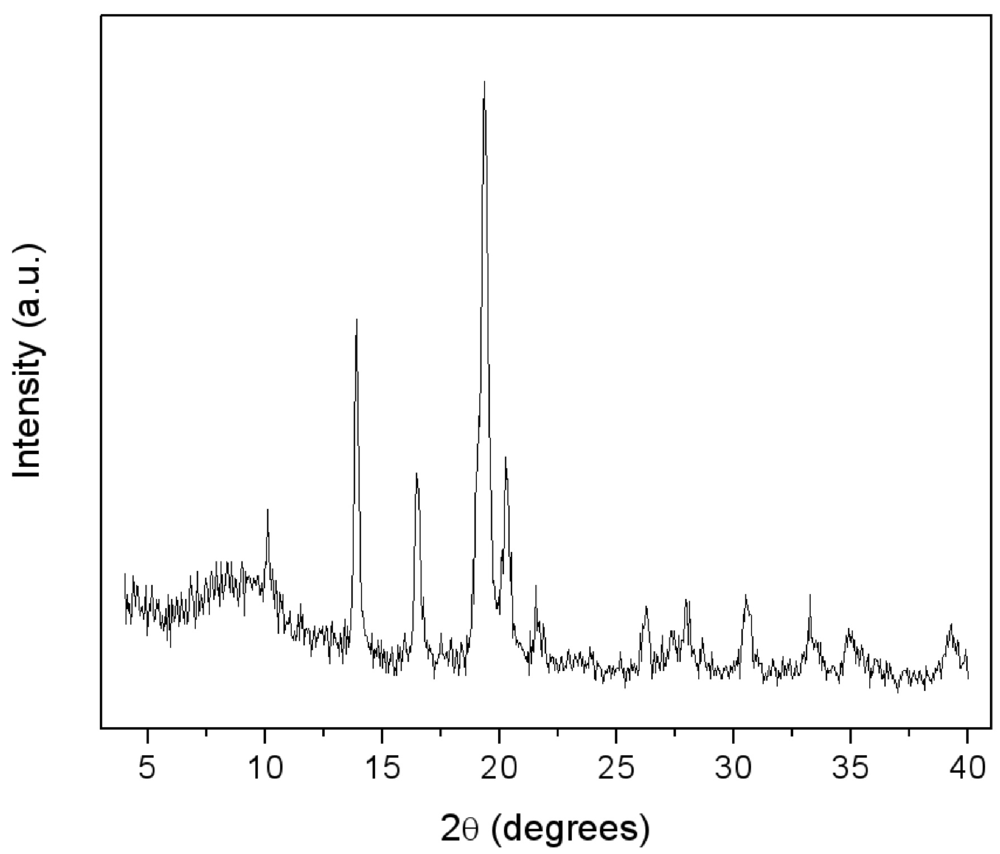
Figure 5. .XRD patterns of LaNi5-SiO2|300 composite.
Crystals 02 00690 g005
On the basis of these results, the temperature of 300 °C was chosen to perform the annealing of the LaNi5-SiO2 blend under Argon atmosphere.
The XRD spectrum of the consolidated composite LaNi5-SiO2|300 is reported in Figure 5. Again, the growth of new crystalline phases possibly induced by the thermal treatment is not detectable and the crystallite dimensions of the LaNi5 alloy remained unchanged. A more evident halo appeared at low angles, typical of amorphous compounds.

3.2. Morphological Characterizations

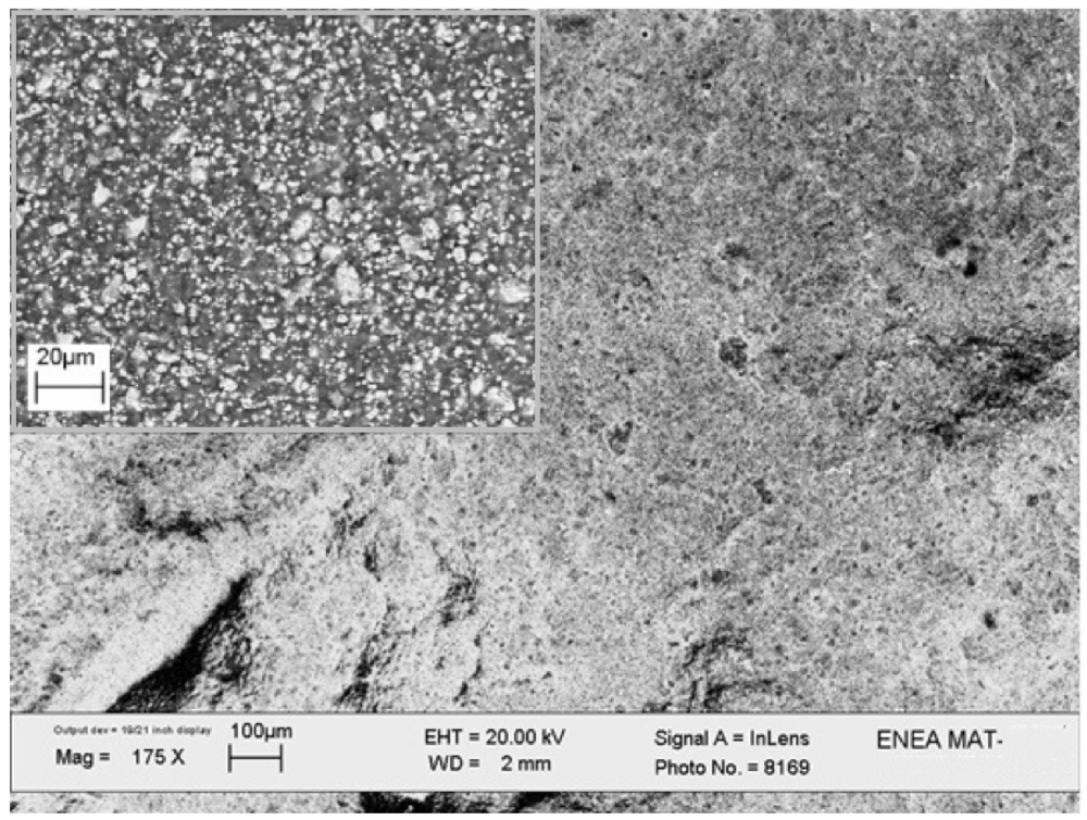
SEM images of the consolidated sample are reported in Figure 6. The microscopy analysis demonstrates the porous surface of the composite, with metal particles uniformly embedded within the matrix (see the backscattered image in the inset).
Figure 6. SEM image of the LaNi5-SiO2|300 composite. The inset shows the image acquired in the backscattered mode.
Crystals 02 00690 g006
In Figure 7 the nitrogen adsorption isotherms obtained for the SiO2 powder at 77 K, the LaNi5 powder, the consolidated pure silica matrix at 300 °C and the LaNi5-SiO2|300 are reported. In Table 1, data resulting from isotherm analyses are summarized. By applying the BET equation, the surface area (SBET) of pristine pyrogenic silica resulted 245 m2/g, corresponding to an average equivalent spherical diameter d ≈ 10 nm (the overall powder surface is considered as the sum of single spherical particle surfaces).
Figure 7. Normalized nitrogen adsorption isotherms at 77K for: (a) LaNi5-SiO2|300; (b) LaNi5 powder; (c) SiO2|300 consolidated sample; (d) SiO2. V0.4 are: (a) 12cm3/g; (b) 3.6cm3/g; (c) 70 cm3/g; (d) 84.6cm3/g.
Crystals 02 00690 g007
Table 1. .Samples surface (S) pores dimension (L0) and equivalent particle diameter (d) resulting from nitrogen adsorption analysis.
SBET (m2/g)α-plot Sext (m2/g)DR Methodd (nm)
Smic (m2/g)L0 (nm)
SiO2245---------10
(SiO2)|300---65821.6---
LaNi50.5---------1500
LaNi5-SiO2|300---17171.6---
The effect of the network formation on sample surface area and pore size can be deduced from the annealed silica pellet analysis. The obtained isotherm (see Figure 7c) falls in type I IUPAC classification [16], which is typical of microporous systems. The evidenced microporosity is mainly brought by the silica phase and especially by the residual internal void volume of the aggregates. By applying the DR analysis to the SiO2|300 data, a microporous surface (Smic) of 82 m2/g and an average pore dimension L0 ≈ 1.6 nm (slit-like shape model) result. The external surface (Sext) was evaluated by using the α-plot method, obtaining a dimension of ~65 m2/g, the total surface area (Stot) being ~147 m2/g. The decrease of the total surface from 245 to 147 m2/g due to the heating treatment, as well as the presence of micropores, indicate that condensation occurred among the silica particles. The LaNi5 isotherm (type II) exhibits a very low surface area, (SBET~0.5 m2/g), corresponding to particles with an equivalent spherical diameter d of 1.5 μm.
Analysis of the final composite LaNi5-SiO2|300 isotherm (type I + II), performed by using DR and α-plot methods, gives 17 m2/g for the micropores surface, pore size ~1.6 nm, 18 m2/g external surface and a total surface area of 35 m2/g, a value very close to the one resulting from BET elaboration. It is worthy to note that both the annealed samples (LaNi5-SiO2|300 and SiO2|300) possess identical pore size, a consequence of the identical reticulation phenomenon. The measured Stot (35 m2/g) is lower than the expected area as can be calculated by linear combination of total surfaces of single components of the blend (~50 m2/g by considering LaNi5:/SiO2 mass ratio). The observed decrease in surface area can arise from the interpenetration of alloy particles into silica aggregate structure. However, the surface area loss can also derive from metal-silica adhesive interfaces growth, due to the formation of metal silicate compounds, as reported in the following paragraph. The observed amorphous signal increase after thermal treatment supports the latter hypothesis (see Figure 5 and Figure 2b).

3.3. Material Behaviour to the Hydrogen Adsorption/Desorption Process

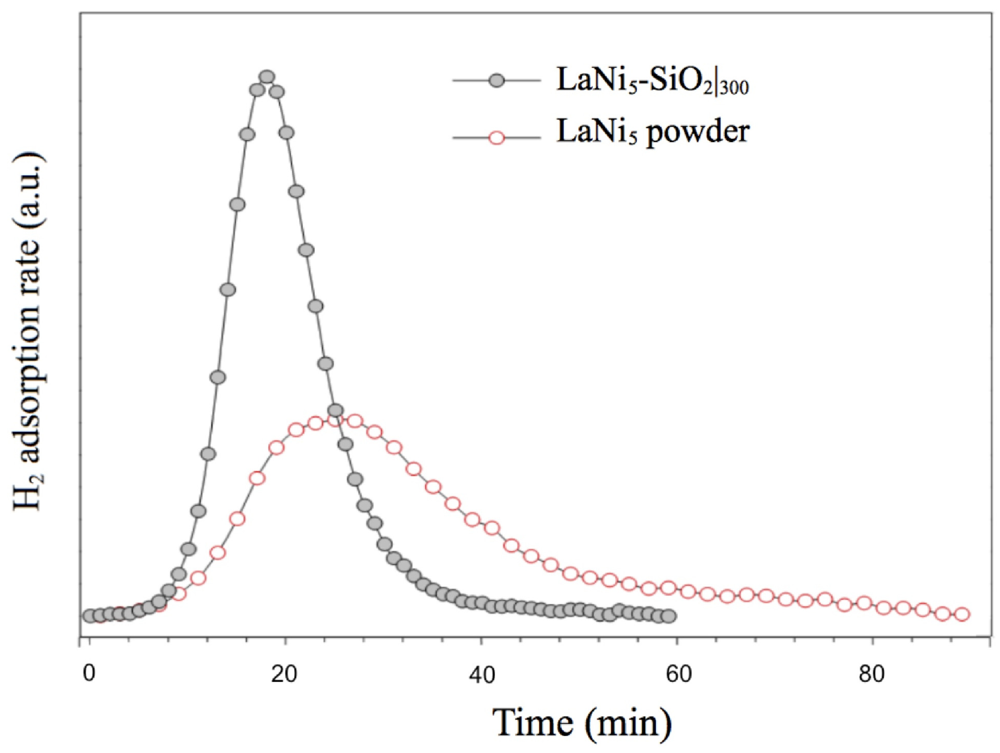
In Figure 8, low H2 pressure (0.03 atm) TPD/TPR analysis of LaNi5-SiO2 composite in comparison with LaNi5 powder are reported. The hydrogenation kinetics show significant differences. The hydrogenation rate of the LaNi5-SiO2 sample is clearly faster than that of pure LaNi5 alloy, since the signal areas represent the total amount of chemisorbed gas comparable. The faster kinetics of the composite cannot simply be derived from microstructural and morphological features of the metallic phase, as the pure alloy is processed in very similar way. A possible explanation can be found in the nucleation of oxides and silicates during the consolidating thermal treatment of the composite.
Figure 8. Activation by low H2 pressure (0.03 atm) of LaNi5-SiO2 composite and LaNi5 powder. The TPD/TPR analysis shows the H2 adsorption isotherms at 100 °C.
Crystals 02 00690 g008
Indirect evidence of the formation of oxidised metal compounds, not detected in the XRD diffractograms (see Figure 5), is given by the Thermal Programmed Desorption (TPD) analysis of a simple compressed powder mixture in pure argon flux. In Figure 9 the gas evolution from the LaNi5-SiO2 substrate is reported. The TPD signal is formed by two different contributions. The first one corresponds to desorption of non bonded water from silica, while the second one, starting at about 150 °C up to the end of the analysis, corresponds to hydrogen emission.
As compacted pure silica can desorb only water, hydrogen necessarily derives from metal oxidation, due to the water. Condensation of silanol groups to form siloxane bridges can promote metal oxidation according to the following reaction (1, 2, 3):
2M + H2O → M2O+H2 (1)
2M + 2SiOH →M2O+SiOSi+H2 (2)
2M + 2SiOH → 2MOSi +H2 (3)
Silicate formation reactions (3), in particular, gives a substantial contribution to the surface area decrease evidenced by the N2 adsorption analysis (see Table 1).
Figure 9. Thermal Programmed Desorption (TPD) analysis of LaNi5-SiO2|300. The signal consists in a low temperature (<300 °C) water flow followed by a consistent H2 flow.
Crystals 02 00690 g009
As reported by Uchida [19] the H2 dissociation in atomic form is a fundamental step for the hydride phase formation. The process is strongly accelerated by the presence of surface oxides and by the porosity brought by the incorporation of the porous silica aggregates, which facilitates the diffusion of the hydrogen inside the mix.
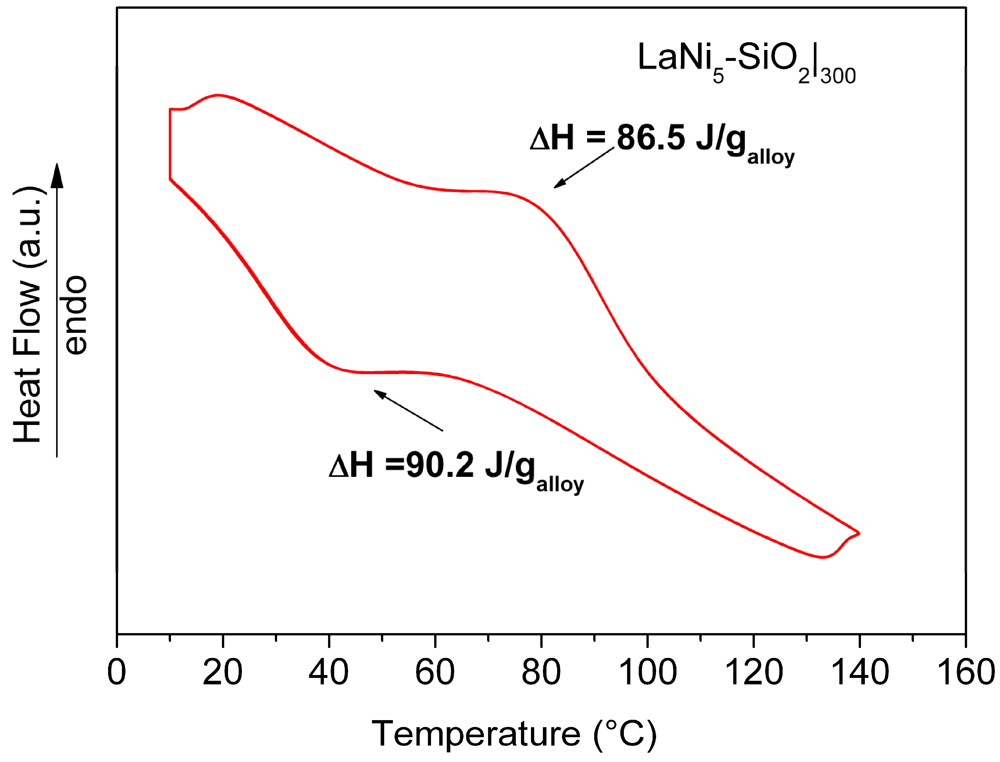
Results of HPDSC measurements performed on the LaNi5-SiO2|300 pellet at 10 atm H2 pressure, are reported in Figure 10. The obtained thermograms do not show significant differences concerning the adsorption-desorption temperatures. The curves relative to the hydrogenation (exothermic signal) and dehydrogenation (endothermic signal) for LaNi5-SiO2|300 show a maximum in heat evolution at 40 °C and 80 °C for the adsorption and desorption reactions, respectively. In comparison with data obtained for a pure LaNi5 sample, no differences in the peak temperature values were found. However, the total amount of the measured heat fluxes (both in the desorption and adsorption stages), are lower than expected (86.6 J/g vs. 93 J/g in the desorption stage and 90.2 J/g vs. 99 J/g in the adsorption stage for LaNi5-SiO2|300 and LaNi5, respectively).
Figure 10. HPDSC analysis of the consolidated LaNi5-SiO2|300 composite. Each thermal trace consists of perfectly overlapped 4 run signals.
Crystals 02 00690 g010
Since the obtained value is directly dependent on the exchanged hydrogen amount, a reduction of the storage capability of the alloy in the composite sample should be observed. The amount of hydrogen absorbed by the embedded metal was estimated to be around 93% with respect to the LaNi5 one. The lower hydrogen storage capability observed for the LaNi5-SiO2|300 confirms the above reported hypothesis about the formation of oxide and silicate nuclei on the metallic surface.
After 40 hydrogenation-dehydrogenation cycles the material showed no visible morphological and structural modifications. In Figure 11 the SEM analysis shows that the silica matrix suitably acts as a dimensional stabilizer. The metallic particles size appears to be in the same range as the prepared material (1–1.5 μm) and the observed particle fractures were well contained within the silica matrix.
Figure 11. Pictures of LaNi5-SiO2|300 composite pellet after 40 hydrogenation/dehydrogenation cycles (pH2 = 10 bar). In the inset, a fractured metal particle is fixed in the bed.
Crystals 02 00690 g011

4. Conclusions

A dimensionally stable composite material formed by LaNi5 alloy particles embedded in pyrogenic silica matrix has been realized by mechanical treatment of a Mish-metal based alloy and fumed silica dry powders, followed by uniaxial cold pressing and thermal treatment at 300 °C.
The alloy particles are homogenously dispersed in the obtained microporous silica matrix. The study of the first hydrogenation step (activation) carried out by the TPR method has shown higher hydrogenation kinetics for the composite material with respect to the free milled alloy powder, probably due to the formation of oxide and silicate nuclei on the LaNi5 particles surface during the heat treatment. In addition to the beneficial effect on hydrogenation kinetics, the so-formed oxidized phases are also responsible for a total amount of exchanged hydrogen reduction (93% of the expected storage capacity). The silica matrix flawlessly contains the shuttered fine particles and ball milling represents an effective solid-state method for the preparation of porous silica embedded solid alloy particles.

Acknowledgments

This work has been partially supported by the Italian MIUR, FIRB RBPI065NJ3 project, “Development of systems with low consumption and environmental influence for energy production and rationalisation on ships”.

Conflict of Interest

The authors declare no conflict of interest.

References

  1. Nakamura, Y.; Sato, K.; Fujitani, S.; Nishio, K.; Ogur, K.; Uehara, I. Lattice expanding behaviour and degradation of LaNi5-based alloys. J. Alloy Compd. 1998, 267, 205–210. [Google Scholar] [CrossRef]
  2. Joubert, J.-M.; Latroche, M.; Cerny, R.; Percheron-Guégan, A.; Yvon, K. Hydrogen cycling induced degradation in LaNi5-type materials. J. Alloy Compd. 2002, 330–332, 208–214. [Google Scholar] [CrossRef]
  3. Ishikawa, H.; Oguro, K.; Kato, A.; Suzuki, H.; Ishii, E. Preparation and properties of hydrogen storage alloy-copper microcapsules. J. Less Common Metals 1985, 107, 105–110. [Google Scholar] [CrossRef]
  4. Watanabe, F.; Ikai, C.; Hasatanti, M.; Marumo, C. Hydration characteristics of metal hydride fixed in resin form. J. Chem. Eng. Jpn. 1992, 25, 1–5. [Google Scholar] [CrossRef]
  5. Uemura, Y.; Yasutsune, R.; Hatate, Y. Encapsulation of hydrogen storage alloy by polymer. J. Chem. Eng. Jpn. 1991, 24, 377–381. [Google Scholar] [CrossRef]
  6. Moon, S.S.; Nahm, K.S. An improvement in the properties of hydrogen storage alloy by copper microencapsulation. J. Alloy Compd. 1995, 224, 140–147. [Google Scholar] [CrossRef]
  7. Akiyama, T.; Tazaki, T.; Takahashi, R.; Yagi, J. Optimization of microencapsulating and compacting conditions for hydrogen storage alloy. J. Alloy Compd. 1996, 236, 171–176. [Google Scholar]
  8. Heung, L.K.; Wicks, G.G.; Enz, G.L. Composition for Adsorbing Hydrogen. U.S. Patent 5,411,928/A, 2 May 1995. [Google Scholar]
  9. Heung, L.K.; Wicks, G.G. Silica embedded metal hydrides. J. Alloy Compd. 1999, 293–295, 446–451. [Google Scholar] [CrossRef]
  10. Pentimalli, M.; Padella, F.; La Barbera, A.; Pilloni, L.; Imperi, E. A metal hydride-polymer composite for hydrogen storage applications. Energy Conv. Manag. 2009, 50, 3140–3146. [Google Scholar] [CrossRef]
  11. Pentimalli, M.; Padella, F.; Pilloni, L.; Imperi, E.; Matricardi, P. AB5/ABS composite material for hydrogen storage. Int. J. Hydrogen Energy 2009, 34, 4592–4596. [Google Scholar]
  12. Pentimalli, M.; Frazzica, A.; Freni, A.; Imperi, E.; Padella, F. Metal hydride-based composite material with improved thermal conductivity and dimensional stability properties. Adv. Sci. Tech. 2010, 72, 170–175. [Google Scholar] [CrossRef]
  13. Balaz, P. Mechanochemistry in Nanoscience and Minerals Engineering; Springer-Verlag: Berlin, Germany, 2008. [Google Scholar]
  14. Brunauer, S.; Emmett, P.H.; Teller, E. Adsorption of gases in multi molecular layers. J. Am. Chem. Soc. 1938, 60, 309–319. [Google Scholar] [CrossRef]
  15. Dubinin, M.M. Physical adsorption of gases and vapors in micropores. Progr. Surf. Membr. Sci. 1975, 9, 1–70. [Google Scholar]
  16. Gregg, S.J.; Sing, K.S.W. Adsorption Surface Area and Porosity; Academic Press: London, UK, 1988. [Google Scholar]
  17. Magini, M.; Colella, C.; Iasonna, A.; Padella, F. Power measurements during mechanical milling—II. The case of “single path cumulative solid state reaction”. Acta Mater. 1998, 46, 2841–2850. [Google Scholar] [CrossRef]
  18. Ehrburger, F. The Surface Properties of Silicas; Legrand, A.P., Ed.; John Wiley & Sons Ltd.: Berlin, Germany, 1998; pp. 83–137. [Google Scholar]
  19. Uchida, H. Surface processes of H2 on rare earth based hydrogen storage alloys with various surface modifications. Int. J. Hydrogen Energy 1999, 24, 861–869. [Google Scholar] [CrossRef]