1. Introduction
In view of possible applications in optical processing technology, about two decades ago it was shown that the limitations associated with multiple diffraction originated in the Raman–Nath regime can be overcome by a 2D grating structure. In this case, even using a thin film, it is possible to obtain Bragg diffraction. The demonstration was given using photopolymers [
1] and semiconductors as supporting materials [
2], obtaining in this case high efficiency and wavelength selectivity. A theoretical treatment to account for the experimental results was also reported [
3]. In the last decade, such 2D configuration has been considered using chiral liquid crystals for developing applications related to near-eye displays. The use of liquid crystals with helicoidal order easily provides a self-assembled periodic arrangement in one direction, allowing the realization of another periodic order in a transversal plane to get a full 2D grating structure. In 2016 [
4] the team led by S.-T. Wu reported the study of the diffraction properties of a polarization volume grating (PVG) based on cholesteric liquid crystals (CLCs) in order to exploit the larger diffraction angle of the Bragg diffraction with respect to the Raman–Nath regime. The realization of these gratings is based on the method proposed by Cipparrone and coworkers [
5] that uses a photoalignment technique for realizing a PVG with efficiency close to 100%. This was made possible by a periodic rotation of the liquid crystal director on the boundary surfaces that produce the required periodic order along a transversal direction. Using this method different scientists have investigated this 2D structure based on CLCs, making clear the basic optical properties of these devices under different physical conditions. See for instance references [
6,
7,
8,
9,
10,
11].
In these structures the longitudinal periodicity given by the helicoidal arrangement of the CLC has the characteristic length
Λz =
p/2, where
p is the pitch of the CLC. The 2D structure is formed by combining the imposed transverse periodicity with a length of
Λy, resulting in Bragg planes that are slanted by an angle of φ with respect to the boundaries of the sample. It is easily found that the Bragg period is given by Λ
B =
Λysin φ =
p/2
cos φ [
4].
Beside conventional planar CLCs, another liquid crystal configuration predicted by Meyer [
12] and de Gennes [
13] in 1968 and discovered in 2014 by the group led by Oleg Lavrentovich [
14] has attracted much interest because the Bragg resonance becomes easily tunable in the full visible range by application of a low frequency electric field [
15,
16] and/or by optical beam [
17]. In this state, known as oblique helicoidal cholesteric (ChOH) or heliconical cholesteric, a low-frequency electric field
ES induces a stable arrangement of the molecular director on a conical surface while rotating around the helical axis parallel to the applied electric field, thus being described by
where
is the azimuthal angle of the rotation and
θ is the conical angle with respect to the helix axis. This configuration can be obtained if the bend elastic constant
K3 is lower than the twist elastic constant
K2 (i.e.,
κ =
K3/
K2 < 1) and the electric field has a value between two critical fields dependent on the material parameters:
.
The above-mentioned tunability of the Bragg resonance is due to the dependence of the helix pitch on the applied electric field and on impinging light intensity according to the following expression [
18]:
where
p0 is the pitch of the unperturbed cholesteric,
C depends on material parameters, and the critical field
, where Δ
ϵS is the dielectric anisotropy at the frequency of the field
ES.
Taking into account the property of ChOH given by Equation (1), it is possible to envisage the realization of a 2D Bragg structure where the longitudinal periodicity is given by the heliconical configuration and the transversal periodicity is obtained by a pitch modulation induced by a modulated electric field or a modulated light intensity impinging on the sample. In one case the use of interdigitated electrodes on one boundary of the ChOH sample makes different voltages applied to different locations possible thus allowing a spatially periodic modulation of the applied field. In the second case, an interference image patterned on the sample can provide the required modulation of the impinging intensity.
In this paper, we report a study based on computer simulations of the optical diffraction properties of a ChOH structure with periodic modulation of pitch. To our knowledge, only one theoretical work has been reported so far concerning 2D gratings in ChOH and is related to the PVG configuration [
19]. The aim of this work is to investigate the optical diffraction properties of a 2D structure never consider before as having peculiar features that may provide original functionalities to be exploited in optical devices.
In
Section 2, we describe the investigated structure, presenting the basic theoretical background and the method used for computer simulation.
Section 3 is devoted to results and discussion of the general properties of the double diffraction originated by this structure, while in
Section 4 we highlight the possibility of tuning one diffraction with respect to the other one and switching off the double diffraction using an applied field. Conclusions and final comments are given in
Section 5.
2. Physics of 2D Structure and Calculation Approach
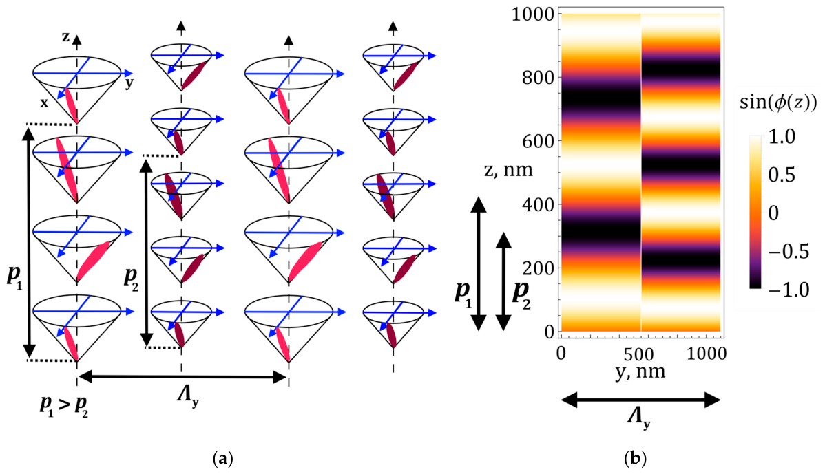
A schematic diagram of the investigated 2D structure based on ChOH is shown in
Figure 1. The structure is made by periodic alternation of stripes of different pitches
p1 and
p2.
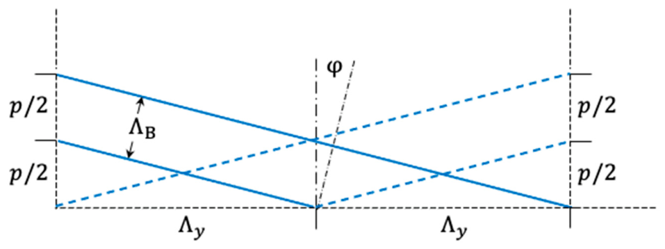
Following a scheme previously proposed [
4], coupling the orthogonal periodic modulations of the refractive index along
y (
Λy) with the one of the ChOH along
z (
p/2) one obtains slanted Bragg planes as shown in
Figure 2. The figure shows the series of symmetric planes that give rise to diffraction on two sides of the incident light beam as we will show in the following discussion.
Due to the presence of structures with two different pitches
p1 and
p2 we expect two series of symmetric Bragg planes with different inclinations and different periods [
4]:
and
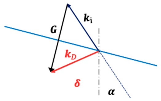
The basic diffraction properties of this system can be obtained by applying the momentum conservation for the wavevector of the incident beam
ki (dark blue color), the grating vector
G (black color) and the wavevector of the diffracted beam
kD (red color) as shown in
Figure 3.
The general grating vector is given by:
Since we are considering light at normal incidence or at a small value of the incidence angle
α, in the following we take
q = 1. In fact, higher orders of diffraction in ChOH have been observed only for
α > 45° [
20,
21,
22].
Then, the momentum conservation equation
becomes
where
δ is the diffraction angle and
nav is the average refractive index of the helical structure.
From Equation (6) both the wavelength and the angle of the diffracted beam are easily found:
At normal incidence
α = 0 and
m = ±1 Equations (7) and (8) reduce to:
i.e., on the opposite sides of the normal boundary at an angle of +
δ (
m = +1) and −
δ (
m = −1) we have the first-order diffractions at the same wavelength
.
It is straightforward to show that under this condition
The investigation of the optical properties of this 2D grating was implemented using a finite element method (FEM) in the software package COMSOL Multiphysics (version 6.2, Wave Optics Module), which was used in order to get full-wave electromagnetic simulations in the Electromagnetic Waves, Frequency Domain.
In the Frequency Domain, the physics of wave propagation within the micro-structured domain is dictated by the vector Helmholtz equation:
where
E denotes the electric field,
k0 represents the wavenumber in free space, and
εr and
μr are the spatially dependent relative permittivity and permeability, respectively. For the non-magnetic materials used in our study
μr = 1. The equation is solved with appropriate boundary conditions.
The finite element method (FEM) transforms a continuous boundary-value problem into a discrete algebraic system by subdividing the computational domain into a finite number of non-overlapping elements (triangles or quadrilaterals in two dimensions). Within each element, the unknown field variable (e.g., displacement, pressure, or potential) is approximated as a linear combination of polynomial shape functions that depend only on the nodal degrees of freedom. Substituting this approximation into the governing differential equation and applying the Galerkin weighted-residual method yields a set of local integral equations. The local matrices are then assembled into a global system matrix according to the connectivity of the mesh, while essential and natural boundary conditions are imposed to modify the system accordingly.
Owing to the translational symmetry in the transverse (out-of-plane) dimension, we used a 2D cross-sectional geometry. This dimensionality reduction allows for a substantial decrease in memory usage and simulation time while preserving the precision of the in-plane light interactions. The symmetry of the problem allows us to divide it into two parts. There is no change in optical properties along the x-axis, so the solution to Maxwell’s equations will coincide with the solution in an infinite homogeneous medium (a plane wave). Meanwhile, the second part of the solution (in the 2D zy-plane, where periodic changes in the structure’s properties are observed) depends on the z and y coordinates and can be found using the FEM.
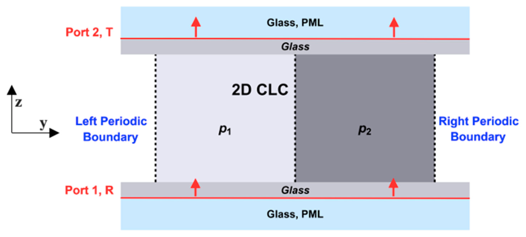
Figure 4 shows a schematic representation of the computational domain in COMSOL Multiphysics. The key elements are described in the following.
Ports: An incident plane wave was launched from an input periodic port in order to evaluate the reflection coefficient (
R), while the transmission coefficient (
T) was calculated from the corresponding output port.
Boundaries: To simulate an unbounded propagation environment and prevent parasitic reflections at the boundaries of the area, PMLs (Perfectly Matched Layers) were placed at the top and bottom surfaces perpendicular to the wave vector. Meanwhile, Floquet periodic conditions were applied along the transverse directions in order to represent mimic an infinitely repeating periodic array and to account for the phase shift between adjacent elements.
Mesh: The maximum size of the element was fixed at
λ/(5
nmax), where
nmax is the highest refractive index in the domain. To check the reliability of the computational results a mesh convergence test was performed by iterative increasing the spatial resolution until the relative change in the transmission spectrum was below 1%.
To set up the problem correctly, we used the Three-component vector and Full field settings in the “Electromagnetic Waves, Frequency Domain”. Waves with circular and linear polarizations were defined in the Input Port domain with an input power of 1 [W/m]. In the Port mode settings domain, we used the following vectors to specify the polarizations: for LHCP—(1, 0, −j), for RHCP—(1, 0, j), and for linear polarization—(1, 0, 0). The mode phase was set to 0 rad. In this case, E0 is assumed to be 1. The diffraction orders were calculated automatically in the Diffraction Order domain, with the In-plane vector and Out-of-plane vector components calculated separately for each order.
The step-like approximation that we are using between the two sections of different pitch in the computational area represents a possible limitation of our approach since the defect area present at the boundary is not taken into account. As a matter of fact, this problem occurs several times when dealing with a grating structure realized in liquid crystals either by light-induced effects or by interdigitated electrodes. In most cases investigated in the past decades, simple grating models neglecting defects at the boundary zone have been used to fit the experimental data in a satisfactory way. The main effect of diffuse boundaries has been found to be a reduction in the expected diffraction efficiency due to the decrease in the spatial resolution. Of course, only experimental findings can determine the limit of our approximation; however, it appears very reliable in determining the spectral locations of the diffracted beams. In the next section we show that the calculated wavelengths of the diffracted beams differ by less than 0.5% from the values expected by a simple application of the Bragg condition.
The material parameters used in the calculation are the ones reported in ref. [
16] for the multi-component mixture M:E7:CB7CB:S811 made by the flexible dimers M (Merck, Darmstadt, Germany), the rod-like mesogens E7 (Merck, Darmstadt, Germany), the heptane CB7CB, and a chiral dopant S811 (Merck, Darmstadt, Germany) in the composition ratio 45.5:30.3:20.2:4.0. The dielectric permittivities at optical frequency are
ϵ‖ = 2.79,
ϵ⊥ = 2.19, the low frequency dielectric anisotropy Δ
ϵS = 4.79, the optical dielectric anisotropy Δ
ϵ =
ϵ‖−
ϵ⊥ = 0.6,
κ =
K3/
K2 = 0.1, the unperturbed helix pitch is
p0 = 1400 nm. The critical fields defining the range of existence of the heliconical configuration are
ENC = 4.88 V/μm and
.
When considering normal or nearly normal incidence of light we can write the dielectric permittivity matrix at optical frequencies as reported in [
18] following the Berreman’s approach [
23,
24,
25]:
where
q = 2
π/
p1,2,
,
.
In case of oblique incidence, a matrix with nonzero xy and yz components must be used [
21]. Anyway, relevant effects due to oblique incidence have been observed for angles
α ≥ 45° [
20,
21,
22], and in our case much lower diffraction angles are involved as we show in the next section.
For a unit cell located along the
y-axis:
θi is the tilt angle of each helix:
Calculations have been performed for different layer thickness ranging between
d = 5 and 20 μm. According to Equation (1) at
I = 0 the minimum and maximum pitch allowed by the structure are respectively:
pmin =
p0κ = 140 nm and
. The selected refractive index of the external medium is equal to
Left-handed helix has been considered, where the molecular director rotates counterclockwise around the helix axis parallel to the oriented
z-axis, according to the conventional de Gennes’ representation [
26].
To calculate the diffraction efficiency in COMSOL, the full solution for the field is decomposed into plane waves corresponding to different diffraction orders. After solving the FEM problem, COMSOL obtains the full electromagnetic field in the computational domain. Then, for each port (and each diffraction order associated with it), the S-parameters are calculated. Physically, an S-parameter is a transmission coefficient (the ratio of the complex amplitude of the transmitted wave of order m to the amplitude of the incident wave). Similarly, is the reflection coefficient for order m. Each diffraction order is represented as a plane wave with a specific wave vector km and polarization. The amplitude of this wave is determined by the field overlapping integral at the boundary between the port and the mode field. The diffraction efficiency is the fraction of the incident wave’s power that is diffracted into a given order. It is calculated as the square of the absolute value of the corresponding S-parameter (taking into account normalization to impedance, but COMSOL does this automatically): and
3. Results and Discussion
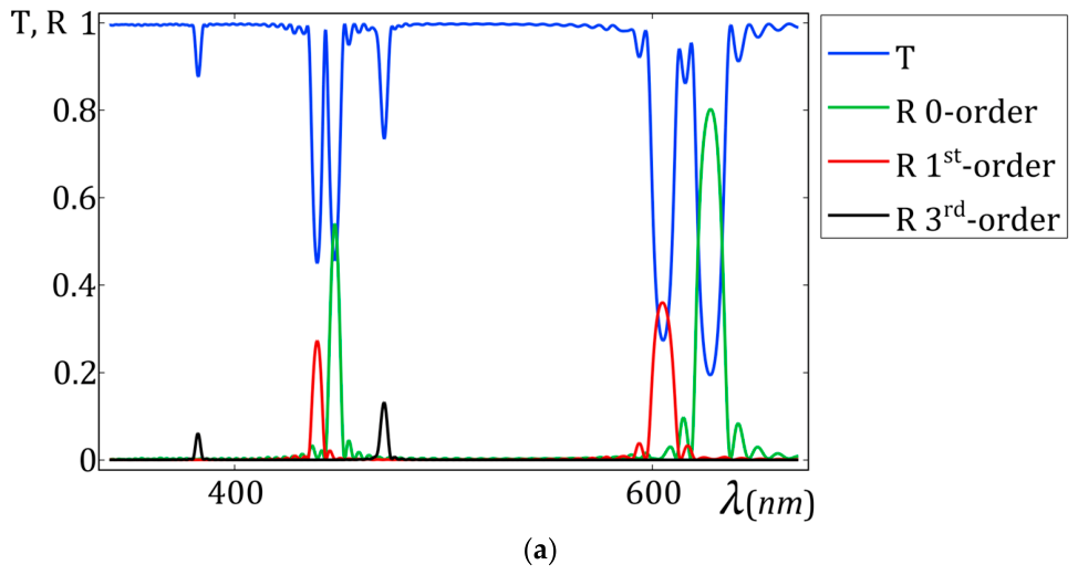
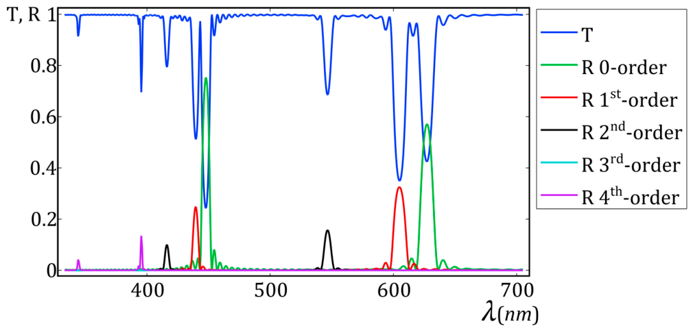
Typical transmission and reflection spectra obtained for left-handed circular polarization (LHCP, the same handedness of the ChOH) for light impinging at normal incidence are shown in
Figure 5a. The upper side of the curve reports the transmission spectrum of the 2D grating structure, while the lower curves refer to the observed reflections related to different order of diffraction. For the sake of clarity, we define “0-order” the back reflection which originated only fromthe helical structure and is present in the usual ChOH sample.
The reflection spectra help in identifying the origin of minima of the transmission.
As expected, beside the own reflection typical of the 1D usual configuration each heliconical structure gives rise to some diffracted beams originated by the slant Bragg planes depicted in
Figure 2.
The calculated 0-order peaks reported in the figure correspond to the Bragg back reflection of the two helical structures with pitch
p1 = 420 and
p2 = 300, that is:
where
.
The peak closest to each of them on the blue side of the spectrum is due to the first-order diffraction of the correspondent 2D structure. In fact, from Equation (9) we get:
Values that satisfactorily fulfill the ones obtained from the simulations presented in
Figure 5a:
We should note that these peaks correspond to the symmetric ±1 order of diffraction on opposite sides of the normal to the boundary, as shown by Equations (9) and (10). Their diffraction angles are: δ1D = ±21.6° and δ2D = ±15.5°. The presence of the ± orders of diffraction that overlap with each other must be taken into account when checking the fulfillment of the condition R + T = 1 at each wavelength by neglecting losses.
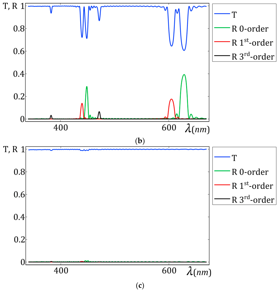
The important role of light polarization is shown in
Figure 5b,c where transmission and reflection spectra are reported for incident light with linear polarization (either along
x or
y direction) or with right-handed circular polarization (RHCP).
In the first case (
Figure 5b), the peaks are lower than in the previous case because only the resonant component (LHCP) of the linear polarization takes part in the process. In the second case (
Figure 5c), no selective reflection is observed, because the left-handed helix does not affect the RHCP light beam.
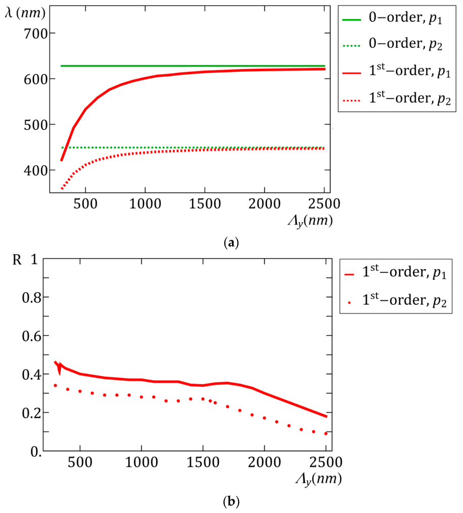
Looking at Equations (9)–(11) we see that a critical parameter determining the 2D grating diffraction properties is the ratio
p/2
Λy between the lengths characterizing the periodic modulations. Accordingly, we expect that 2D structure becomes less and less effective as
Λy increases with respect to
p. This is made clear by
Figure 6 where the wavelength (
Figure 6a) and the reflectance (
Figure 6b) of the first-order diffracted beams are reported for increasing value of
Λy. For both diffractions (originated either by
p1 or
p2) we observe merging of the diffracted peak towards the wavelength of the 0-order diffraction of the correspondent heliconical structure. In fact, when
Λy ≈ 6
p1 the diffraction peaks originated by the 2D structure merge into the 0-order reflection because the 2D Bragg planes become superimposed to the Bragg planes of the 1D heliconical structure, even if a partial contribution to the overall reflectance is still observable in
Figure 6b.
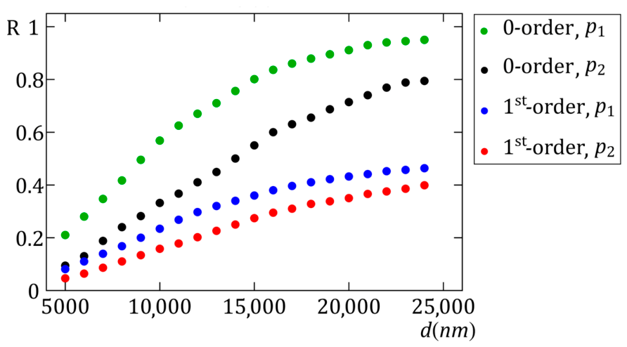
The effect of the sample thickness
d on double diffraction is shown in
Figure 7. While the wavelength of all the diffracted beams is not dependent on
d, the reflectance increases with thickness approaching a saturation of the effect for
d~25 μm, while a significant double diffraction is already observed at
d = 10 μm. It is remarkable that these values are usually considered pretty low even to get efficient Raman–Nath diffraction in liquid crystals and do not allow the achievement of the thick grating condition required to observe Bragg diffraction in these materials. On the contrary, as already pointed out in the pioneering works on 2D structure realized in polymers and semiconductors [
1,
2,
3] this double periodic configuration leads to Bragg diffraction even in thin samples.
Additional insight on the diffraction process is given by plotting the instantaneous real part of the complex amplitude of the electric field in the
y-z plane at
t = 0. Since the field distribution for
p2 helixes have a similar behavior, we show here the field distribution only at wavelengths related to the effects originated by helices with period
p1. In
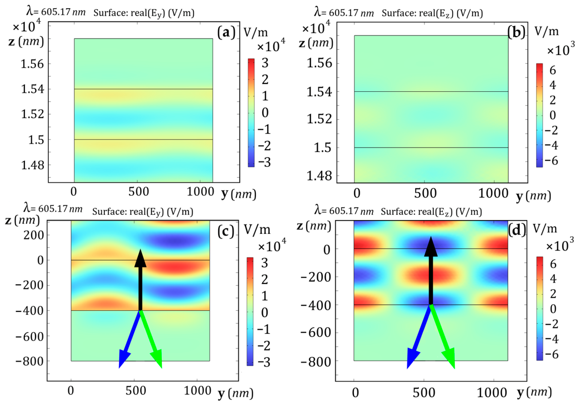
Figure 8, we show the distribution of the real part of the
y- (a,c) and
z-components (b,d) of the complex electric field phasor within a unit cell of the 2D structure, in the regions of the output (a,b) and input (c,d) ports. The field was calculated at the central wavelength of the ±first-order reflection peak and
for the
p1 helix. The black arrow represents the wave vector of the incident wave. The blue and green arrows represent the wave vectors for the +1st and −1st reflection orders. From this field distribution, we conclude that each higher order of diffraction consists of positive and negative orders. The field distribution at these wavelengths can be easily explained by analyzing the observed physical phenomena. At a wavelength of 605.17 nm, we have the symmetric +1 and −1 reflection orders. As a result, two plane waves are simultaneously present in the reflection zone (in front of the ChOH structure), which gives a characteristic picture of the
z-component of the field. For normal incidence, the
z-component of the field is present only in higher-order waves; therefore, we can easily detect their presence as well as their propagation direction.
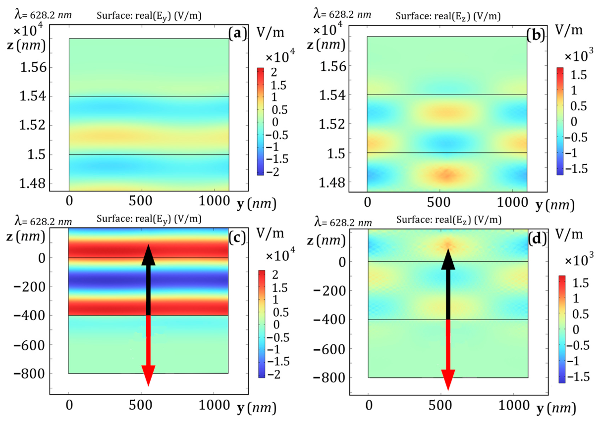
Next, consider the distribution of the real part of the
y- and
z-components of the complex electric field phasor at wavelength of the 0-order (
λ0D = 628.2 nm), as shown in
Figure 9. The red arrow represents the wave vector of the reflected wave. In this figure, we observe a sinusoidal field distribution in the reflection zone in front of the structure, that corresponds to an ordinary plane wave. We can observe only the
y-component here, which is a sine wave varying along the
z-axis, confirming the absence of higher orders. The zero-order reflection wave propagates along the same direction of the incident wave; therefore, it does not modify the shape of the field distribution.
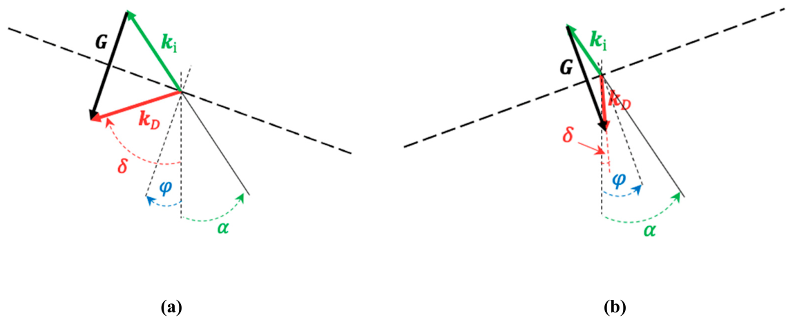
It is interesting to underline that the symmetry between the positive and negative orders of diffraction is lost when the incidence angle
α is not zero. This is described by Equations (7) and (8) where we can recognize for small values of
α that diffraction orders with
m < 0 correspond to longer wavelengths and lower diffraction angles with respect to diffraction orders with
m > 0. A visual explanation of the effect is obtained by comparing the geometry of the Bragg condition depicted in
Figure 2 for symmetric Bragg planes in case of oblique incidence, as shown in
Figure 10.
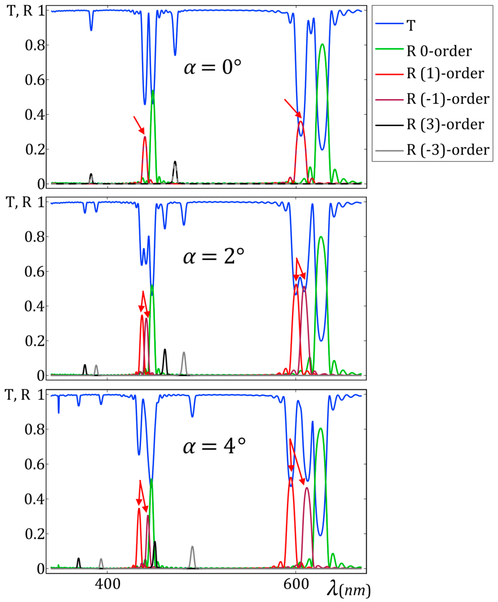
The consequence is easily observed in the diffraction spectrum. In fact, by increasing the angle of incidence by a small amount the peaks correspondent to the 2D double diffraction split into two peaks because
. This is evident from
Figure 11 where transmission and reflection spectra are reported for the observed diffraction phenomena comparing the normal incidence spectrum (upper plots) to the one correspondent respectively to angle of incidence
α = 2° and
α = 4°.
Looking, for instance, at the reflection peaks of the first-order diffractions highlighted by the red arrows in the figures, we see that a single peak at α = 0° splits into two well defined peaks at α = 2° that are completely separated from each other at α = 4°.
A peculiar feature of all the spectra discussed above is the absence of diffraction peaks correspondent to even orders. In order to explain this observation, we need to note the properties of binary amplitude gratings. In fact, for this type of grating, the period Λ
y can be expressed as the sum of two regions with different transmittances:
Λy =
d1 +
d2 (for a conventional transmission grating, the transmittances of the two regions are
t1 = 1 and
t2 = 0). It is well-known [
27,
28] that the intensity of the diffraction orders depends on the fill factor
a =
d1/
Λy, where
d1 is the thickness of the strip with pitch
p1. This can be expressed as follows:
where it is evident that some diffraction order will have zero diffraction efficiency depending on the value of the fill factor
a. Our structure made by two series of periodic ChOH stripes with different pitches can be seen as two amplitude diffraction gratings with fill factors
a1 and
a2 because they give rise to different transmission bands.
All the above reported spectra have been calculated considering a1 = a2 = 1/2 that is when both ChOH helical structures have the same width Λya1 = Λya2. Additionally, the values a and 1 − a are equivalent as they lead to the same efficiency. For this reason, according to Equation (16) all the even orders are suppressed for both ChOH configurations, because a1 = 1 − a2.
In order to highlight this point, we repeated the calculation for different fill factors using the same parameters as in the previous figures. An example of the resulting spectrum is shown in
Figure 12 where the fill factors
a1 = 1/3 and
a2 = 2/3 were chosen. As expected, in this case the even order diffractions are not suppressed as evident in the figure. At the same time, third-order suppression is observed.
4. Tuning and Switching of Double Diffraction
In the following we show that the peculiar properties of 2D ChOH can be exploited to provide some original feature to this device. In fact, according to previous work [
12,
13,
14,
15,
16,
17,
18], the value of the pitch of a ChOH configuration is dependent on the applied field
ES and the light intensity
I of a “pump” beam as summarized by Equation (1). This makes it possible to change the value of
p1 while keeping fixed
p2 or vice versa. For the sake of clarity in explaining this concept, we choose the case
I = 0, when the 2D structure is realized by using interdigital electrodes. The case
I ≠ 0 just makes the mathematical expressions a bit less uncomfortable without changing the consequent phenomenon. When
I = 0 Equation (1) reduces to
It means that the chosen pitches
p1 and
p2 of the 2D structure have been obtained by applying the fields
Using the same material parameters of the previous sections this means ES1 = 1.62 V/μm to get p1 = 420 nm and ES2 = 2.27 V/μm to get p2 = 300 nm.
It is possible to change p1 while keeping p2 fixed, by changing only the value of ES1, i.e., changing the applied voltage for only one series of ChOH stripes by a variable amount ΔE: while .
As a consequence, according to Equation (7) the wavelength of the diffraction
λ1D will be tuned according to the new value of the applied field
while keeping
λ2D fixed (of course the effect is present on all the orders of diffractions originated by
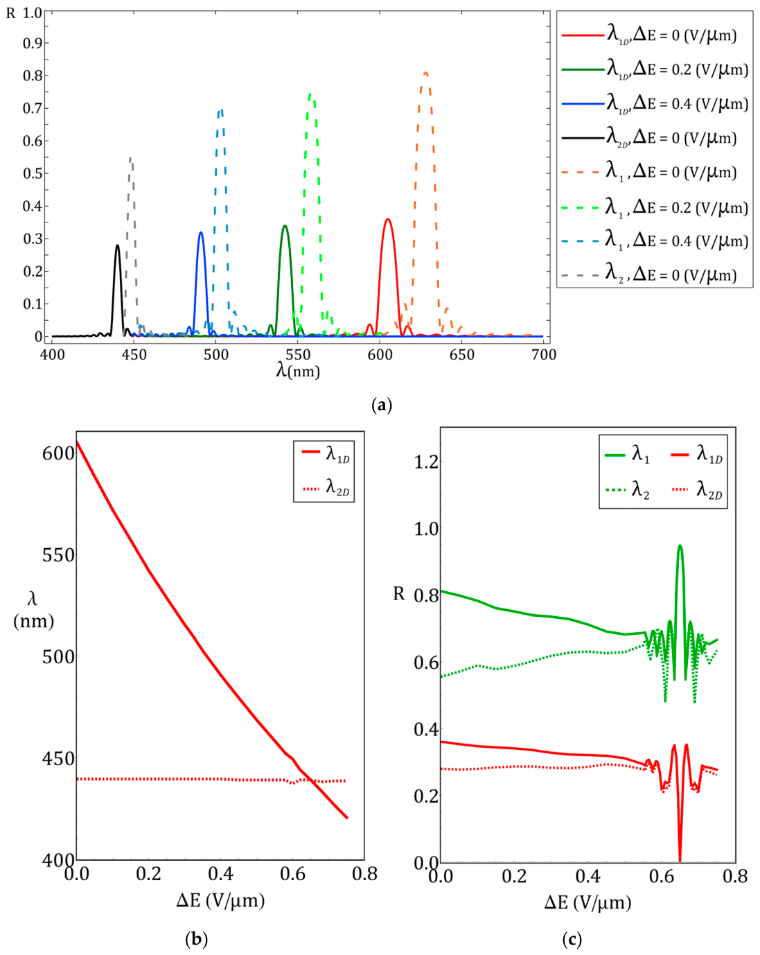
p1). This effect is reported in
Figure 13a where the reflection spectrum of the first-order diffracted beams and the zeroth-order components for different values of Δ
E are plotted. Here the blue shift of
λ1D and
λ1 is shown, approaching
λ2D and
λ2 for increasing values of the field, as expected.
The results are summarized in
Figure 13b,c where on the left side the wavelength of the two diffracted beams is reported vs. Δ
E, while on the right side we show the reflectance of the zero- and first-order diffractions.
Blue shift in the first diffraction at λ1D is evident with a slow decrease in both diffraction efficiency up to the value ΔE = 0.65 V/μm correspondent to p1 = p2 where the 2D structure disappears and the first-order diffraction efficiency goes to zero while at the same time the back reflection of the uniform ChOH reaches its maximum. At ΔE = 0.65 ± 0.02 V/μm, a change in the diffraction efficiency of the back reflection is observed in the range from 0.948 to 0.554, and a change in the ±1st-order is observed in the range from 0.0047 to 0.35.
It is quite interesting that this field switches off the 2D structure because it produces a uniform arrangement with pitch p2. Nevertheless, by a further increase in the field we get p1 < p2 and the diffraction appears again. We have not reported here the further increase in diffraction efficiency that is obtained when ES1 > ENC that leads to unwinding of the structure with pitch p1 leading to uniform vertical orientation of the director in the correspondent stripes.
The oscillations near the switching point arise because, as the 0 and first orders for p1 and p2 approach each other near the switching point, the edge local maxima of all peaks begin to overlap with each other and with the main peaks, which directly affects the local increase and decrease in the reflectance of the main peaks. In addition, when different peaks merge with one another, their amplitudes change abruptly.
It also has to be underlined that wavelength tuning corresponds, at the same time, to tuning of the diffraction angle, thus providing an additional feature to this original optical structure. In other words, we can sweep the first diffraction in wavelength and angle with respect to the other one and quench any diffraction when In fact, using an electric field, it is easy to transform our cholesteric material from two-dimensional to one-dimensional, which distinguishes it from all other PVG or ChOH gratings investigated previously.
It is important to remark that a practical limitation of this tuning property can be derived from the long range orientational correlation of the liquid crystal molecules which can also modify the ChOH configuration where the electric field does not change. Anyway, several examples of liquid crystal gratings realized with interdigitated electrodes and driven by variable electric field have been demonstrated and proposed as novel diffractive optical devices [
29]. An important parameter that can limit the diffraction efficiency in these cases is the electrode pitch, i.e.,
Λy in our scheme. Possibly, the chosen value
Λy = 1.1 μm might be a critical one reducing the effective visibility of the phenomenon due to the mentioned liquid crystal property, while a higher value would be more comfortable to exploit the tuning effect. On the other hand, the drawback of increasing
Λy is to have a less effective 2D structure as shown in
Figure 6. Our choice has been determined by the material parameters correspondent to a compound with known physical characteristics and it was made to point out the possible occurrence of the tuning effect. In practice, this means that it can be more easily exploited in the near-infrared region of spectrum using ChOH with longer pitch where the condition
Λy < 6
p1 can be smoothly fulfilled.