
Separable Magnetic Fe3O4@MoS2 Composite for Adsorption and Piezo-Catalytic Degradation of Dye

1
Hubei Water Resources Research Institute, Hubei Water Resources and Hydropower Science and Technology Promotion Center, Wuhan 430070, China
2
College of Science, Huazhong Agricultural University, Wuhan 430070, China
3
Shanghai Foreign Language School, Shanghai International Studies University, Shanghai 200083, China
4
Central Research Institute of China Chemical Science and Technology Co., Ltd., Beijing 100083, China
*
Author to whom correspondence should be addressed.
Catalysts 2021, 11(11), 1403; https://doi.org/10.3390/catal11111403
Submission received: 31 October 2021
/
Revised: 14 November 2021
/
Accepted: 15 November 2021
/
Published: 20 November 2021
Abstract
:Well-designed composite catalysts are of increasing concern due to their improved performance compared to individual components. Herein, we designed and synthesized an Fe3O4@MoS2 composite via a simple hydrothermal method. As for the resultant composite, the MoS2 nanolayers presented a novel piezo-catalytic effect, while the Fe3O4 core provided a magnetic separation property. The structure and properties of Fe3O4@MoS2 were determined by relevant experiments. It was found that Fe3O4@MoS2 exhibited enhanced piezo-catalytic degradation of rhodamine B and good magnetic recovery/recycling features. The kobs for rhodamine B degradation over Fe3O4@MoS2 was 0.019 min−1—a little longer than that over MoS2 (0.013 min−1). Moreover, Fe3O4@MoS2 also showed a favorable ability to adsorb rhodamine B in solution, with a saturation adsorption of 26.8 mg/g. Further studies revealed that piezo-electrons, holes, and superoxide anions were key species in the piezo-catalytic degradation of rhodamine B. Notably, the step where oxygen trapped electrons to produce superoxide anions had a significant impact on the degradation of the dye. This work, not limited to the development of a high-performance MoS2-based piezo-catalyst, is expected to provide new insights into the working mechanisms and process profiles of composite piezo-catalysts.
1. Introduction
Researchers have developed various water treatment technologies, including photocatalytic, electrocatalytic, and biocatalytic processes, to achieve effective removal of pollutants [1,2,3,4,5,6]. Since the concept of nano-piezoelectronics was proposed by Wang in 2006 [7,8], the ensuing study of piezo-catalysis has gradually attracted significant interest from researchers [9,10,11]. Piezo-catalysis based on mechanically induced charges has been found to be an effective and promising strategy to reduce environmental pollution and energy shortage problems by means of low-frequency energy in nature [12,13]. In recent years, many piezo-catalysts—such as BiFeO3, MoS2, and g-C3N4—have been developed to expand their applications in hydrogen generation, sterilization, degradation of organic pollutants, etc. [14,15,16].
Among these studies, piezo-catalysis as an emerging advanced oxidation technology for the efficient degradation of organic pollutants from water is particularly notable, and has been the most reported [17,18,19]. Recently, MoS2 with few layers was reported to have a novel piezo-catalytic effect as a result of its central asymmetric structure, thus presenting ultrahigh activity for the degradation of dyes [19,20,21,22]. Among these, composite piezo-catalysts based on piezoelectric nanomaterials such as MoS2 are gradually becoming more and more attractive [23]. Similar to the design of composite photocatalysts, a well-designed composite piezo-catalyst can combine the functions of each component and produce a synergistic boost [24]—for example, to inhibit electron–hole complexation by conducting electrons out of the piezoelectric material, or to increase the binding capacity of the substrate by introducing a new component, thereby increasing the local concentration of the substrate on the surface of the piezo-catalyst [25]. Whether the composite piezo-catalyst has a different piezoelectric catalytic mechanism to that of single components is also a question worth investigating. For emerging nano-piezo-catalysts, such as MoS2, g-C3N4, studies that have reported them to increase catalytic activities have often focused on tuning the energy level structure in heterogeneous junctions, or adding sacrificial reagent to inhibit the complexation of electrons and holes [15,21]. Studies using cheap and simple methods to achieve spatial separation of electrons and holes in the piezo-catalysis process and, thus, to improve the catalytic performance, have not been reported. Furthermore, the recovery of the nanomaterial from the solution is still a problem that extremely restricts its application [26]. Likewise, insufficient attention has been paid to the recyclability of nano-piezo-catalysts. Magnetic separation is a low-cost and convenient separation technique, whereby the magnetic material can be separated and recovered from the solution with an external magnetic field; for example, a commonly used magnetic material is Fe3O4 [27,28]. Therefore, a composite material composed of MoS2 and Fe3O4 can be recovered with a magnetic field. For example, a MoS2–Fe3O4 composite, which was prepared by depositing Fe3O4 nanoparticles on the surface of a nanolayer of MoS2, was reported to be separated from water by its magnetism [29]; however, the corrosion of the Fe3O4 nanoparticles, such as ion exchange and dissolution in acidic water, must be considered—especially when the composite is used as a catalyst for a long time. Therefore, on the premise that the composite has excellent piezoelectric and catalytic properties and magnetic separation, the composite is better if it possesses a structure in which the Fe3O4 is completely covered by the MoS2, which can protect the Fe3O4 from erosion.
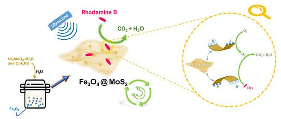
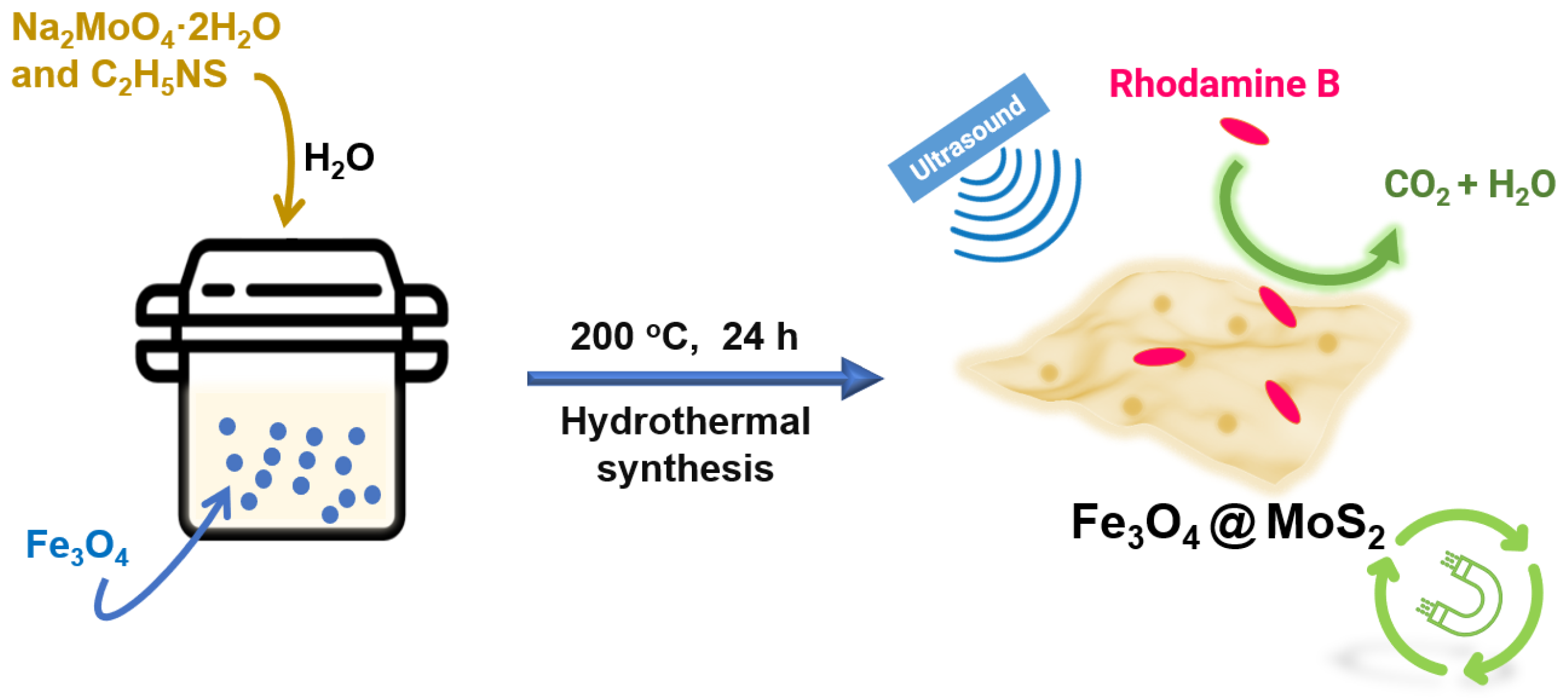
To validate the above strategy, the Fe3O4@MoS2 was prepared in our work as shown in Scheme 1, where the MoS2 layers were generated in situ on the Fe3O4 nanoparticles; thus, the Fe3O4@MoS2 was a core–shell structure, and not a simple mechanical mixture of the MoS2 and the Fe3O4. Fe3O4 was selected as one functional component in part because of its magnetic properties, which could make its composite magnetically separable from the solution. In addition, Fe3O4 has usually been considered as a conductor, with a high electronic conductivity of 1.9 × 10⁶ S⋅m−1 [30], which was found to be beneficial for electron transport and, theoretically, might enhance the piezo-catalytic effect. Rhodamine B was selected as the dye contaminant because of its common use. The performance and mechanism of adsorption/piezo-catalytic degradation of rhodamine B over the Fe3O4@MoS2 were studied and discussed in detail.
2. Results and Discussion
2.1. Structure and Composition of Materials
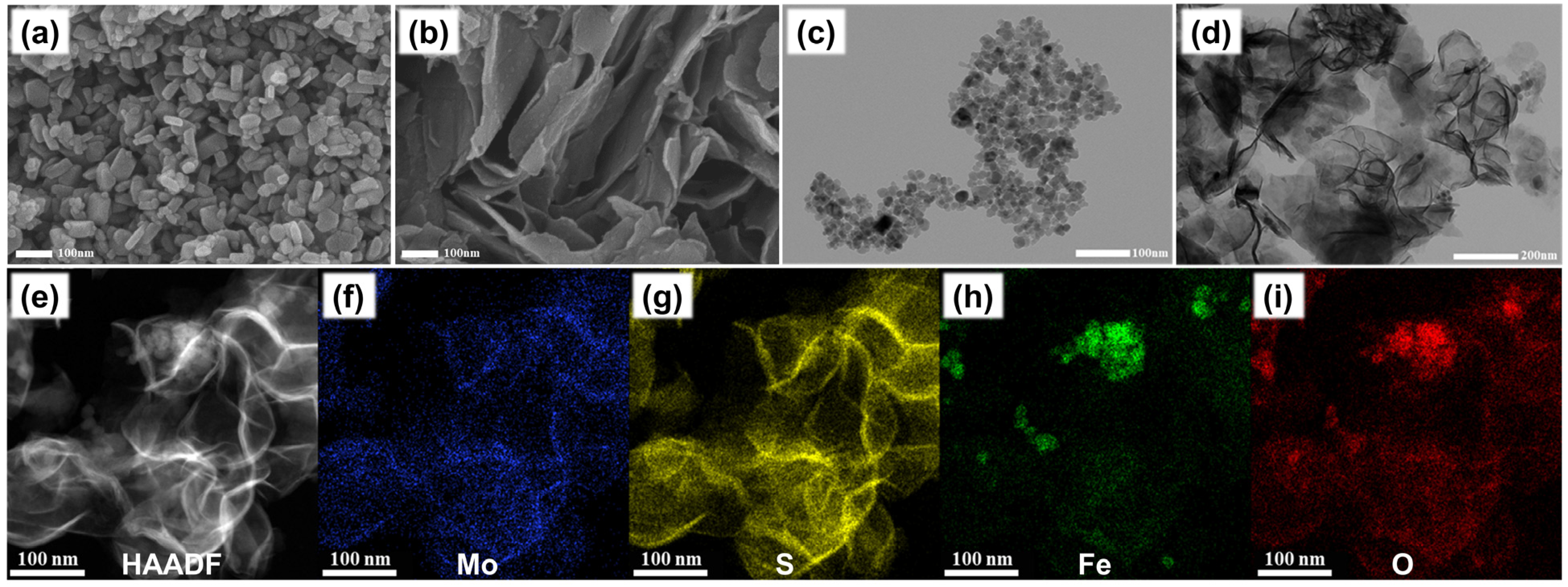
The structural morphologies of the as-prepared Fe3O4@MoS2 and its precursor Fe3O4 were characterized by SEM and TEM, as shown in Figure 1. The Fe3O4 sample was essentially spherical in shape, with a particle size of ca. 50 nm (Figure 1a,c). After being covered with a MoS2 layer generated in situ, the Fe3O4 core was wholly enveloped and the Fe3O4@MoS2 presented a 2D layer structure for the MoS2 component, where the thin layers of MoS2 could be clearly observed (Figure 1b,d). The elemental distribution of the Fe3O4@MoS2 was investigated via TEM mapping. As shown in Figure 1f,g, the Mo and S were uniformly distributed, and the shape was consistent with the HAADF-STEM image (Figure 1e); thus, it can be presumed that the lamellar structure was composed of MoS2. In contrast, there were regions of relatively high concentration in the distribution of Fe and O (Figure 1h,i), revealing that most of the Fe3O4 nanoparticles were coated with MoS2 in the form of particle aggregates resulting from mutual magnetic attraction between the Fe3O4 nanoparticles. Accordingly, the Fe3O4@MoS2 had a nanosheet structure, with the MoS2 layer outside and the Fe3O4 component wrapped and protected inside.
The phase structures of the Fe3O4@MoS2 and the Fe3O4 were investigated via XRD. As shown in Figure 2a, the peaks located at 2θ = 30.4°, 35.7°, 43.5°, 53.9°, 57.4°, and 63.1°—corresponding to the lattice planes of (220), (311), (400), (422), (511), and (440), respectively—were consistent with the Fe3O4 standard card (PDF#85–1436) [31]. The Fe3O4 phase (PDF#85–1436) had a cubic crystal structure and Fd3m space group, and its lattice parameters were a = b = c = 8.39 and α = β = γ = 90°. These peaks were apparent in the XRD pattern of the Fe3O4 nanoparticles, while they were unclear or absent in the XRD pattern of the Fe3O4@MoS2, which could be ascribed to the crystallinity of the Fe3O4 component having declined after the hydrothermal treatment. Simultaneously, the Fe3O4@MoS2 also retained the characteristic peaks of MoS2, which were located at 2θ = 14.5°, 29.1°, 33.7°, 37.7°, 41.3°, and 47.9°, corresponding to the lattice planes of (003), (006), (102), (104), (105), and (107) of MoS2 (PDF#89–3040), respectively [32]. The MoS2 phase (PDF#89–3040) had a rhombohedral crystal structure and R3m space group, and its lattice parameters were a = b = 3.17, c = 18.38 and α = β = 90°, γ = 120°. The tiny peak at 2θ = 26.4° was probably attributable to the (310) plane of Fe3O4, but was displaced to a higher angle by ~0.3° compared to the standard PDF#85–1436, which may be related to the residual stress in the material after the hydrothermal treatment. Based on these XRD results, the as-prepared Fe3O4@MoS2 was confirmed to be a binary composition of Fe3O4 and MoS2. XPS measurements were further performed to explicate the chemical composition of the surface of the Fe3O4@MoS2. As shown in Figure 2b, the Fe3O4@MoS2 hybrid consisted of four elements—Fe, O, Mo, and S—while the Fe3O4 nanoparticles did not possess either Mo or S. The high-resolution XPS spectra of Mo 3d and S 2p for the Fe3O4@MoS2 are shown in Figure 2c,d. In the Mo 3d spectrum, the four peaks at 233.4 eV, 232.1 eV, 229.8 eV, and 228.7 eV were assigned to Mo5+ 3d3/2, Mo4+ 3d3/2, Mo5+ 3d5/2, and Mo4+ 3d5/2 of MoS2, respectively [33,34]. Mo5+ was a higher valence transition state of Mo4+, which was likely to be involved with additional oxygen in the coordination. The small peak at 235.9 eV corresponded to Mo6+ 3d3/2 of MoO3, which might be an oxidation byproduct during the hydrothermal synthesis. The peak at 226.4 eV corresponded to the S 2s of MoS2. In the case of the S 2p spectrum shown in Figure 3d, there were two peaks at 161.5 eV and 162.6 eV, which corresponded to S2−2p3/2 and S2−2p1/2, respectively [33,34]. In addition, the peaks at 163.8 eV and 168.9 eV proved the existence of the S–O bond and the unsaturated sulfur element on the surface of MoS2, respectively [35]. These XPS results characterized the valance of Mo and S, and further confirmed the successful conjugation of the MoS2 component onto the Fe3O4 core.
2.2. Adsorption and Piezo-Catalytic Degradation of Rhodamine B over Materials
M–H hysteresis loop tests of the Fe3O4 and the Fe3O4@MoS2 were carried out, the results of which are shown in Figure 3a. The saturation magnetization of Fe3O4 and Fe3O4@MoS2 was ca. 55 emu/g and 27 emu/g, respectively. The Fe3O4@MoS2 composite preserved one-half of the magnetism of the Fe3O4, which was enough for magnetic separation. The BET surface area of the Fe3O4@MoS2 (18.4 m2/g) was lower than that of the Fe3O4 nanoparticles (76.3 m2/g), even though a layered framework was provided by the MoS2 component (Figure 3b). This might be related to the fact that the Fe3O4 nanoparticles were tightly enclosed by the MoS2 layers, and had no contribution to the specific surface of the composite [36]. In addition, the initial pores with a size of ~10 nm in the Fe3O4 also disappeared almost completely after being encapsulated by the MoS2 layers, indicating that the tight and completely wrapped structure blocked these pores. These experimental results are consistent with those of the foregoing TEM, where the Fe3O4 nanoparticles were found to be coated with MoS2 in the form of particle aggregates. The Fe3O4@MoS2 had a smaller surface area than the Fe3O4 nanoparticles, but a much higher adsorption of the dye, rhodamine B. As shown in Figure 3c, the adsorption of rhodamine B onto the Fe3O4@MoS2 increased as the equilibrium concentration of the dye increased. The adsorption data were fitted well by the Langmuir model with a saturation adsorption of 26.8 mg/g, and the adsorption closed to saturation at a low concentration (40 mg/L). This indicates that the adsorption of rhodamine B onto the Fe3O4@MoS2 is a monolayer physical adsorption, and the adsorbent has a good affinity for the adsorbate. In contrast, the Fe3O4 nanoparticles had almost no adsorption capacity for rhodamine B. The adsorption effect is generally dependent on the specific surface area of the adsorbent and the strength of the interaction between it and the adsorbate [37]. As shown in Figure 3d, the surface of the Fe3O4@MoS2 was had a negative charge and, thus, had an electrostatic attraction to the positive quaternary ammonium salt, rhodamine B. The Fe3O4 had a large specific surface are, but was positively charged and, therefore, unable to adsorb the rhodamine B well. Piezo-catalytic reactions often occur on the catalyst surface, so the good ability of the Fe3O4@MoS2 to adsorb rhodamine B contributes to its catalytic performance [13,17,18].
Piezo-catalytic degradation of rhodamine B over the materials was performed under a 40 kHz ultrasonic wave (250 W). Figure 4a depicts the normalized changes in the rhodamine B concentration over time during the piezo-catalytic process, which began after an adsorption equilibrium in the dark. It was found that simple sonication was ineffective in removing rhodamine B from the aqueous solution. The Fe3O4@MoS2 showed a high ability to efficiently remove rhodamine B under ultrasonic excitation, with a kobs of 0.019 min−1 (R2 = 0.99), following the first-order kinetic model. In the previous discussion, it was found that the Fe3O4@MoS2 had a good adsorption capacity for rhodamine B, with KL equal to 0.17 L/mg, but the ct ~ t data here were not satisfactorily fitted by the Langmuir–Hinshelwood model. The Langmuir–Hinshelwood kinetic equation, r = k × KL × ct/(1 + KL × ct), accounting for both adsorption and reaction on the substrate, considers that the substrate must first be adsorbed onto the catalyst surface before the reaction occurs. Therefore, the surface reaction is not the only pathway for this kinetic process, and a variety of ROS may exist in the reaction system for the piezo-catalytic degradation of the dye by the Fe3O4@MoS2. In addition, the performance of the Fe3O4@MoS2 was better than that of both of its components, i.e., Fe3O4 and MoS2. The Fe3O4 was not stable during prolonged sonication, and underwent acoustic erosion. MoS2, with fewer layers, is a typical and efficient piezoelectric catalyst. The reaction rate constant of the as-prepared MoS2 was 0.013 min−1 (R2 = 0.98), which was a little lower than that of the Fe3O4@MoS2. Such performance differences between Fe3O4@MoS2 and MoS2 might be due in part to the Fe3O4 component, which could accelerate the charge transfer in the Fe3O4@MoS2, thus helping the separation and transport of electron–hole pairs during the piezo-catalytic process. A similar phenomenon occurs frequently in the photocatalytic process of Fe3O4-containing composites. Moreover, increasing or decreasing the oxygen content of the aqueous solution correspondingly promoted or suppressed the piezoelectric catalytic activity of the Fe3O4@MoS2, respectively, with a kobs of 0.027 min−1 (R2 = 0.99) or 0.011 min−1 (R2 = 0.99). These results imply that oxygen plays an important role in the piezo-catalytic degradation of rhodamine B over Fe3O4@MoS2, which will be discussed below. The stability of the catalyst is an important issue for its practical application. With the best performance, the Fe3O4@MoS2 with fresh air continuously purged was further examined for its reusability in four cycles of adsorption and piezo-catalytic degradation (Figure 4b). The removal rate of rhodamine B after adsorption–degradation remained above 85% over four cycles. The above experimental results show that the Fe3O4@MoS2 had low loss after multiple magnetic collections, and maintained its catalytic activity over a long period of time, revealing that it has the ability to treat wastewater at a large scale and to serve for a long time. We also examined the total organic carbon removal rates during the piezo-catalytic degradation of rhodamine B in the presence of Fe3O4@MoS2 (with fresh air). As seen in Figure 4c, half of the rhodamine B in the solution was mineralized to inorganic carbon after 1 h of piezo-catalytic degradation, indicating that there was not a simple process of dye decolorization, but an advanced oxidation process for the removal of the dye.
2.3. Mechanism of Piezo-Catalytic Degradation
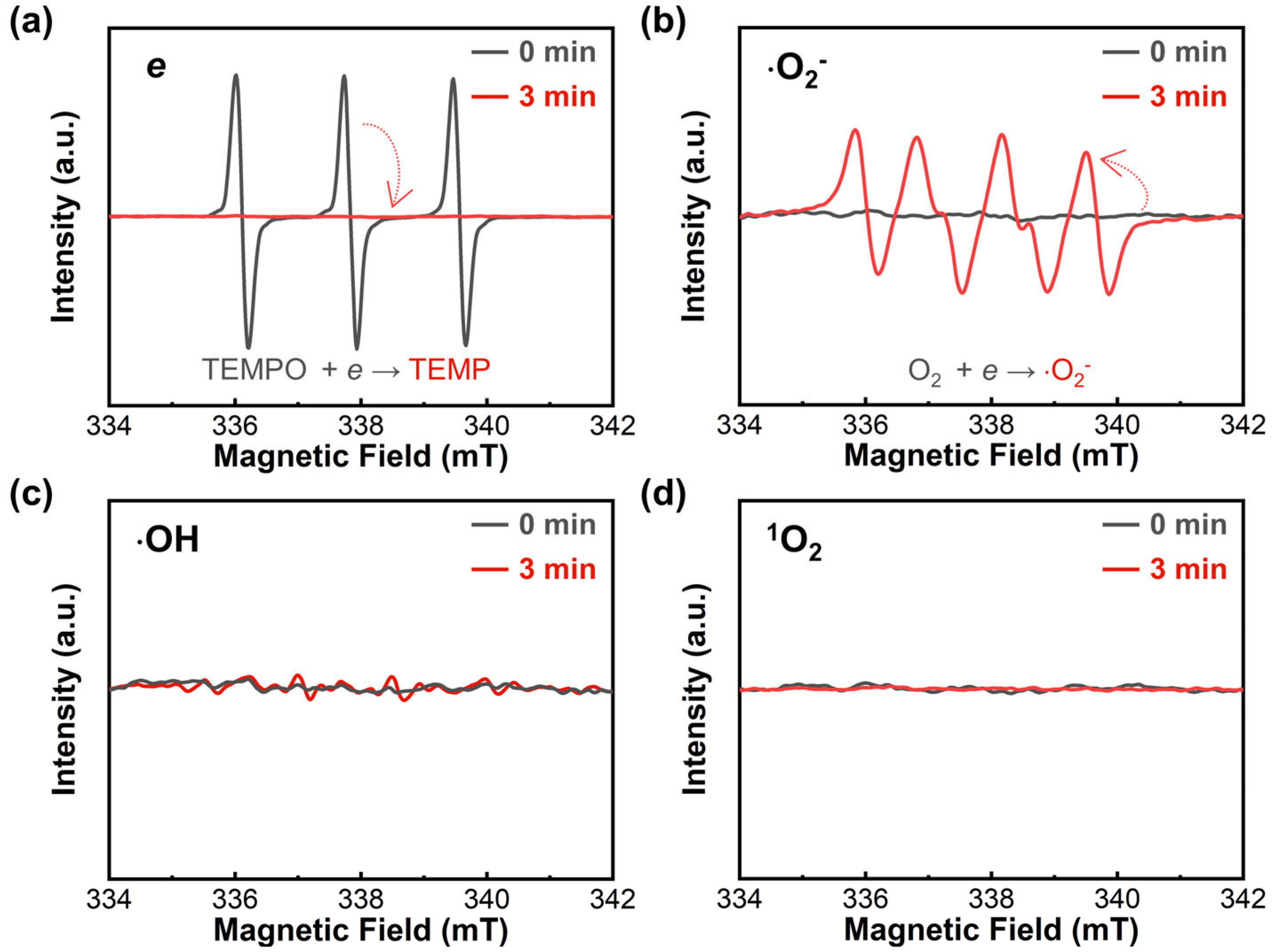
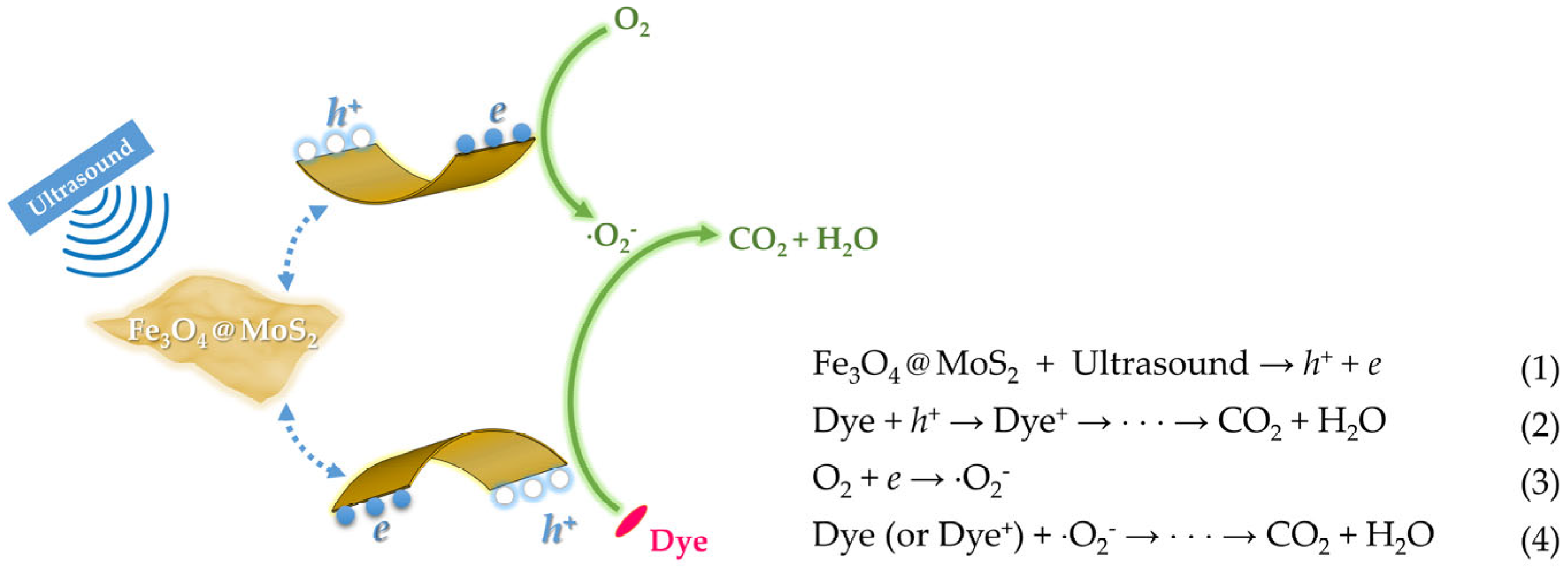
To verify the reactive species during the piezo-catalytic process of the Fe3O4@MoS2, the corresponding EPR analyses (Figure 5) were further performed. When the Fe3O4@MoS2 was irradiated with ultrasonic waves for 3 min, electrons (e) and superoxide anions (⋅O2−) were clearly detected in the piezo-catalytic system. This suggests that the Fe3O4@MoS2, due to the piezoelectricity of the MoS2 component, generated a lot of piezo-electrons under the impact of the ultrasound, while these electrons were easily trapped by oxygen in the solution—which, in turn, formed a large quantity of ⋅O2− [38]. However, there was no singlet oxygen (1O2) generated in the system, implying that these electrons in the excited state might not have undergone a significant intersystem crossing process [38]. Moreover, the Fe3O4@MoS2 system produced very few hydroxyl radicals (⋅OH), indicating that the hole—the positive charge generated via the piezoelectric response—was not able to effectively oxidize water to ⋅OH, while the piezoelectric effect of a few layers of MoS2 can generate large amounts of ⋅OH [22,39]. This suggests that the introduction of the Fe3O4 component changes the proportion of reactive oxygen species (ROS) in the MoS2-contained system. In short, the presence of a large number of electrons in the system under ultrasonic excitation confirms that the Fe3O4@MoS2 has a piezoelectric response; the presence of ⋅O2− and the absence of 1O2 reveal the pathway by which oxygen is involved in the advanced oxidation of the system.
Based on the above results and analysis, a possible piezo-catalytic mechanism in the Fe3O4@MoS2 system under ultrasonic irradiation can be proposed, as shown in Scheme 2. The Fe3O4@MoS2 generated numerous piezo-electrons and holes at the MoS2 layer edges under the impact of the ultrasound on its piezoelectricity. The dye could be oxidized directly by the holes. On the other hand, the electrons produced were trapped by oxygen and turned into superoxide anions. The superoxide anion acts as a reactive oxygen species, which reacts further with the dye or the oxidation products of the dye (dye+), ultimately leading to the mineralization of the dye. Finally, it is also worth noting that the good adsorption properties of the material are very much beneficial for the degradation of the dye, because the holes generated by the piezoelectric effect of the catalyst cannot enter the solution directly, and can only oxidize the dye adsorbed on the surface of the material, which is similar to the case of photogenerated holes in photocatalysis [24].
3. Materials and Methods
3.1. Catalyst Preparation
All chemicals were of analytical-grade purity, purchased from Sinopharm Chemical Reagent Co. Ltd., and used directly without further purification. Deionized water was used throughout the synthesis. The Fe3O4 nanoparticles (>99%) were also purchased from Sinopharm Chemical Reagent Co, Ltd. The composite Fe3O4@MoS2 was prepared in situ via the growth of MoS2 on the Fe3O4 nanoparticles to ensure a structure wherein the Fe3O4 component was coated by the MoS2 component [40]. The specific steps were as follows: 30 mg of Fe3O4, 45 mg of Na2MoO4·2H2O, and 90 mg of C2H5NS were dispersed in 30 mL of deionized water. The suspension obtained was transferred into a 50 mL PTFE-lined stainless steel autoclave, and then heated at 200 °C for 24 h. The hydrothermal product was magnetized with a neodymium magnet for one day. Finally, the as-prepared Fe3O4@MoS2 was collected via centrifugation, washed several times with ethanol and distilled water, and then dried at 60 °C. For comparison, the MoS2 was also synthesized via a similar hydrothermal method, without the addition of Fe3O4 nanoparticles.
3.2. Charaterizations
The morphologies and microstructures of the samples were analyzed using a scanning electron microscope (SEM, Sigma300, Zeiss, Inc., Oberkochen, Germany), a transmission electron microscope (TEM, H-7650, Hitachi, Inc., Tokyo, Japan) with a 100 kV accelerating voltage, and a high-resolution transmission electron microscope (HRTEM, JEM-2010F, JEOL, Inc., Tokyo, Japan) with a 200 kV accelerating voltage. The powders of the materials were used directly as samples for the SEM experiments, while dispersions of the materials in water were used to prepare samples for the TEM or HRTEM experiments. The X-ray diffraction (XRD) patterns of the samples were recorded using an X-ray diffractometer equipped with Cu Kα radiation (D8 advance Bruker Inc., Karlsruhe, Germany). The surface elemental composition of the sample was analyzed via X-ray photoelectron spectroscopy (XPS), using an ESCALAB 250Xi system (Thermo Fisher Inc., Waltham, MA, USA) with Mg Kα X-rays as the excitation source, and all of the binding energies were referenced to the C 1s peak at 284.8 eV of the surface amorphous carbon. The M–H curves of the samples were analyzed at 5 K by Quantum Design’s Squid VSM (MPMS). The adsorption and desorption isotherms, pore size distribution, and Brunauer–Emmett–Teller (BET) specific surface area of nitrogen were measured at 77 K using a nitrogen adsorption–desorption apparatus (Tristar ASAP 2040, Micrometrics, Inc., Cumming, GA, USA). The zeta potential of Fe3O4@MoS2 aqueous dispersions was measured with a laser particle size analyzer (Zetasizer Nano ZSP, Malvern, Inc., Worcestershire, UK). A total organic carbon analyzer (Vario TOC, Elementar, Inc., Langenselbold, Germany) was used to measure the organic carbon concentration of the sample solutions during the piezo-catalytic process. The generation of e, ⋅O2–, ⋅OH, or 1O2 was detected via electron paramagnetic resonance (EPR; MiniScope MS-5000, Magnettech GmbH, Berlin, Germany) with 50 mM 2,2,6,6-tetramethyl-1-piperidinyloxy (TEMPO) in water, 50 mM 5, 5-dimethyl-1-pyrroline-N-oxide (DMPO) in methanol, 50 mM DMPO in water, or 50 mM 2,2,6,6-tetramethylpiperidine (TEMP) in water as the radical spin-trapped reagents under ultrasonic irradiation.
3.3. Measurement of Adsorption and Piezo-Catalytic Activity
The adsorption experiment of rhodamine B onto Fe3O4@MoS2 was carried out as follows: 10 mg of Fe3O4@MoS2 was suspended in a 10 mL aqueous solution containing rhodamine B (20, 40, 60, 80, 100, 150, or 200 ppm). The suspension was stirred in the dark for 12 h to reach the adsorption–desorption equilibrium. Then, it was centrifuged to acquire the supernatant. The concentration of rhodamine B in the supernatant was measured by its absorbance at 553 nm with a UV–Vis spectrophotometer (UV-2450, Shimadzu, Inc., Kyoto, Japan).
The piezo-catalytic degradation activity of the catalysts was evaluated via the decolorization of rhodamine B. A 40 kHz ultrasonic wave (250 W) was applied as a mechanical force on the catalysts in the dye solution. The reactor was equipped with a circulation water-cooling pipe to keep the reaction temperature constant. The piezo-degradation experiment was carried out as follows: 30 mg of the catalyst was suspended in a 30 mL aqueous solution containing 40 mg/L of rhodamine B. The suspension was stirred in the dark for 1 h to reach the adsorption–desorption equilibrium, and then the mixed suspension was exposed to ultrasonic irradiation. Aliquots of 2 mL of the suspension were collected and centrifuged to separate the material at specific time intervals, and the upper clean solution was kept for the subsequent concentration detection. The concentration of rhodamine B was measured using the same method described above. Furthermore, the piezo-catalytic degradation activity of the Fe3O4@MoS2 in aerobic and anoxic environments was also examined, with fresh air and nitrogen gas continuously purged into the reaction suspension, respectively. The symbols c0 and ct were used to represent rhodamine B’s initial concentration and its corresponding concentration at different times during irradiation, respectively. Further analysis revealed that the piezo-catalytic degradation of rhodamine B followed the first-order kinetic model:
where kobs is the reaction rate constant, ct/c0 is the normalized concentration of the residual rhodamine B, and t is the holding time of the ultrasonic wave.
ln(ct/c0) = −kobs × t
4. Conclusions
In summary, we demonstrated the preparation of an Fe3O4@MoS2 composite via simple hydrothermal synthesis. The strategy was to combine the 2D material MoS2 with the magnetic Fe3O4 core in one step. The Fe3O4@MoS2 showed a nanosheet structure, with the MoS2 layer outside and the Fe3O4 component wrapped inside. The Fe3O4@MoS2 was both a good adsorbent and a high-performance piezo-catalyst for removing rhodamine B from water, with a saturation adsorption of 26.8 mg/g and a reaction rate constant of 0.019 min−1. Additionally, it achieved high stability, good capacity for mineralizing organic substances, and sufficient magnetic separability. Furthermore, we also investigated the piezo-catalytic mechanism of the Fe3O4@MoS2 system, and found that the piezo-electrons, holes, and superoxide anions played key roles in the piezo-catalytic degradation of rhodamine B. We demonstrated and explained the effects and pathways of oxygen involved in piezo-catalytic processes. It is hoped that our work will contribute to the development of piezo-catalysts for the removal of pollutants.
Author Contributions
Conceptualization, Z.Y.; methodology, C.Z. and W.L.; formal analysis, C.Z. and W.L.; investigation, W.L. and H.L.; data curation, W.L. and H.L.; writing—original draft preparation, C.Z. and H.L.; writing—review and editing, Z.Y. and M.Y.; supervision, Z.Y.; project administration, Z.Y.; funding acquisition, C.Z. and Z.Y. All authors have read and agreed to the published version of the manuscript.
Funding
This research was funded by the Research Foundation from the Hubei Provincial Department of Water Resources (2019-218-006-001) and the Fundamental Research Funds for the Central Universities (2662019YJ011).
Conflicts of Interest
The authors declare no conflict of interest.
References
- Ye, A.; Fan, W.; Zhang, Q.; Deng, W.; Wang, Y. CdS–graphene and CdS–CNT nanocomposites as visible-light photocatalysts for hydrogen evolution and organic dye degradation. Catal. Sci. Technol. 2012, 2, 969–978. [Google Scholar] [CrossRef]
- Curri, M.; Comparelli, R.; Cozzoli, P.; Mascolo, G.; Agostiano, A. Colloidal oxide nanoparticles for the photocatalytic degradation of organic dye. Mater. Sci. Eng. C 2003, 23, 285–289. [Google Scholar] [CrossRef]
- Xu, M.; Wang, Z.; Wang, F.; Hong, P.; Wang, C. Fabrication of cerium doped Ti/nanoTiO2/PbO2 electrode with improved electrocatalytic activity and its application in organic degradation. Electrochim. Acta 2016, 201, 240–250. [Google Scholar] [CrossRef]
- Ma, H.; Zhuo, Q.; Wang, B. Electro-catalytic degradation of methylene blue wastewater assisted by Fe2O3-modified kaolin. Chem. Eng. J. 2009, 155, 248–253. [Google Scholar] [CrossRef]
- Chen, C.C.; Liao, H.J.; Cheng, C.Y.; Yen, C.Y.; Chung, Y.C. Biodegradation of crystal violet by pseudomonas putida. Biotechnol. Lett. 2007, 29, 391–396. [Google Scholar] [CrossRef]
- Rajaguru, P.; Kalaiselvi, K.; Palanivel, M.; Subburam, V. Biodegradation of azo dyes in a sequential anaerobic-aerobic system. Appl. Microbiol. Biotechnol. 2000, 54, 268–273. [Google Scholar] [CrossRef]
- Wang, Z.L. The new field of nanopiezotronics. Mater. Today 2007, 10, 20–28. [Google Scholar] [CrossRef]
- Wang, Z.L. Piezotronics and Piezo-Phototronics; Springer: Berlin/Heidelberg, Germany, 2012; Volume 24. [Google Scholar]
- Tu, S.; Huang, H.; Zhang, T.; Zhang, Y. Controllable synthesis of multi-responsive ferroelectric layered perovskite-like Bi4Ti3O12: Photocatalysis and piezoelectric-catalysis and mechanism insight. Appl. Catal. B 2017, 219, 550–562. [Google Scholar] [CrossRef]
- You, H.; Jia, Y.; Wu, Z.; Xu, X.; Qian, W. Strong piezo-electrochemical effect of multiferroic BiFeO3 square micro-sheets for mechanocatalysis. Electrochem. Commun. 2017, 79, 55–58. [Google Scholar] [CrossRef]
- Li, S.; Zhang, M.; Gao, Y.; Bao, B.; Wang, S. ZnO–Zn/CNT hybrid film as light-free nanocatalyst for degradation reaction. Nano Energy 2013, 2, 1329–1336. [Google Scholar] [CrossRef]
- Li, S.; Zhao, Z.; Zhao, Z.; Zhang, Z.; Li, X.; Zhang, Z. Recent Advances of Ferro-, Piezo-, and Pyroelectric Nanomaterials for Catalytic Applications. ACS Appl. Nano Mater. 2020, 3, 1063–1079. [Google Scholar] [CrossRef]
- Liang, Z.; Yan, C.; Rtimi, S.; Bandara, J. Piezoelectric materials for catalytic/photocatalytic removal of pollutants: Recent advances and outlook. Appl. Catal. B 2019, 241, 256–269. [Google Scholar] [CrossRef]
- You, H.; Wu, Z.; Zhang, L.; Ying, Y.; Liu, Y.; Fei, L.; Chen, X.; Jia, Y.; Wang, Y.; Wang, F.; et al. Harvesting the Vibration Energy of BiFeO3 Nanosheets for Hydrogen Evolution. Angew. Chem. Int. Ed. 2019, 58, 11779–11784. [Google Scholar] [CrossRef]
- Xu, Q.; Gao, X.; Zhao, S.; Liu, Y.N.; Zhang, D.; Zhou, K.; Khanbareh, H.; Chen, W.; Zhang, Y.; Bowen, C. Construction of Bio-Piezoelectric Platforms: From Structures and Synthesis to Applications. Adv. Mater. 2021, 33, 2008452. [Google Scholar] [CrossRef]
- Yu, T.; Wu, W.; Zhang, J.; Gao, C.; Yang, T.; Wang, X. Piezoelectricity catalyzed ROS generation of MoS2 only by aeration for wastewater purification. Res. Chem. Intermed. 2021, 47, 4763–4777. [Google Scholar] [CrossRef]
- Nie, G.; Yao, Y.; Duan, X.; Xiao, L.; Wang, S. Advances of piezoelectric nanomaterials for applications in advanced oxidation technologies. Curr. Opin. Chem. Eng. 2021, 33, 100693. [Google Scholar] [CrossRef]
- Bößl, F.; Tudela, I. Piezocatalysis: Can catalysts really dance? Curr. Opin. Green Sustain. 2021, 32, 100537. [Google Scholar] [CrossRef]
- Duerloo, K.-A.N.; Ong, M.T.; Reed, E.J. Intrinsic piezoelectricity in two-dimensional materials. J. Phys. Chem. Lett. 2012, 3, 2871–2876. [Google Scholar] [CrossRef]
- Zhu, H.; Wang, Y.; Xiao, J.; Liu, M.; Xiong, S. Observation of piezoelectricity in free-standing monolayer MoS2. Nat. Nanotechnol. 2015, 10, 151–155. [Google Scholar] [CrossRef]
- Wu, J.M.; Chang, W.E.; Chang, Y.T.; Chang, C.K. Piezo-catalytic effect on the enhancement of the ultra-high degradation activity in the dark by single-and few-layers MoS2 nanoflowers. Adv. Mater. 2016, 28, 3718–3725. [Google Scholar] [CrossRef]
- Su, Y.; Zhang, L.; Wang, W.; Li, X.; Zhang, Y.; Shao, D. Enhanced H2 evolution based on ultrasound-assisted piezo-catalysis of modified MoS2. J. Mater. Chem. A 2018, 6, 11909–11915. [Google Scholar] [CrossRef]
- Tu, S.C.; Guo, Y.X.; Zhang, Y.H.; Hu, C.; Zhang, T.R.; Ma, T.Y.; Huang, H.W. Piezocatalysis and Piezo-Photocatalysis: Catalysts Classification and Modification Strategy, Reaction Mechanism, and Practical Application. Adv. Funct. Mater. 2020, 30, 2005158. [Google Scholar] [CrossRef]
- Ding, X.; Xiao, D.; Ji, L.; Jin, D.; Dai, K.; Yang, Z.X.; Wang, S.Y.; Chen, H. Simple fabrication of Fe3O4/C/g-C3N4 two-dimensional composite by hydrothermal carbonization approach with enhanced photocatalytic performance under visible light. Catal. Sci. Technol. 2018, 8, 3484–3492. [Google Scholar] [CrossRef]
- Chen, Y.; Deng, X.M.; Wen, J.Y.; Zhu, J.; Bian, Z.F. Piezo-promoted the generation of reactive oxygen species and the photodegradation of organic pollutants. Appl. Catal. B 2019, 258, 118024. [Google Scholar] [CrossRef]
- Bystrzejewska-Piotrowska, G.; Golimowski, J.; Urban, P.L. Nanoparticles: Their potential toxicity, waste and environmental management. Waste Manag. 2009, 29, 2587–2595. [Google Scholar] [CrossRef]
- Ma, M.; Zhang, Q.; Yin, D.; Dou, J.; Zhang, H. Preparation of high-magnetization Fe3O4-NH2-Pd(0) catalyst for Heck reaction. Catal. Commun. 2012, 17, 168–172. [Google Scholar] [CrossRef]
- Xu, P.; Zeng, G.M.; Huang, D.L.; Feng, C.L.; Hu, S.; Zhao, M.H.; Lai, C.; Wei, Z.; Huang, C.; Xie, G.X.; et al. Use of iron oxide nanomaterials in wastewater treatment: A review. Sci. Total Environ. 2012, 424, 1–10. [Google Scholar] [CrossRef]
- Song, H.J.; You, S.; Jia, X.H.; Yang, J. MoS2 nanosheets decorated with magnetic Fe3O4 nanoparticles and their ultrafast adsorption for wastewater treatment. Ceram. Int. 2015, 41, 13896–13902. [Google Scholar] [CrossRef]
- Verwey, E.J.W. Electronic Conduction of Magnetite (Fe3O4) and its Transition Point at Low Temperatures. Nature 1939, 144, 327–328. [Google Scholar] [CrossRef]
- Oroujeni, M.; Kaboudin, B.; Xia, W.; Jönsson, P.; Ossipov, D.A. Conjugation of cyclodextrin to magnetic Fe3O4 nanoparticles via polydopamine coating for drug delivery. Prog. Org. Coat. 2018, 114, 154–161. [Google Scholar] [CrossRef]
- Ma, W.; Yao, B.; Zhang, W.; He, Y.; Yu, Y. A novel multi-flaw MoS2 nanosheet piezocatalyst with superhigh degradation efficiency for ciprofloxacin. Environ. Sci. Nano 2018, 5, 2876–2887. [Google Scholar] [CrossRef]
- Lu, J.; Zhou, Y.; Zhou, Y.B. Efficiently activate peroxymonosulfate by Fe3O4@MoS2 for rapid degradation of sulfonamides. Chem. Eng. J. 2021, 422, 130126. [Google Scholar] [CrossRef]
- Qi, K.Y.; Yuan, Z.M.; Hou, Y.; Zhao, R.C.; Zhang, B.W. Facile synthesis and improved Li-storage performance of Fe-doped MoS2/reduced graphene oxide as anode materials. Appl. Surf. Sci. 2019, 483, 688–695. [Google Scholar] [CrossRef]
- Zhou, Y.; Zhou, L.; Zhou, Y.B.; Xia, M.Y.; Zhang, J.L. Z-scheme photo-Fenton system for efficiency synchronous oxidation of organic contaminants and reduction of metal ions. Appl. Catal. B 2020, 279, 119365. [Google Scholar] [CrossRef]
- Peng, X.D.; Xiong, C.; Lin, Y.K.; Zhao, C.; Zhao, T.S. Honeycomb-like hierarchical porous silicon composites with dual protection for ultrastable Li-ion battery anodes. SmartMat 2021, 1–12. [Google Scholar] [CrossRef]
- Tan, I.A.W.; Ahmad, A.L.; Hameed, B.H. Adsorption of basic dye on high-surface-area activated carbon prepared from coconut husk: Equilibrium, kinetic and thermodynamic studies. J. Hazard. Mater. 2008, 154, 337–346. [Google Scholar] [CrossRef]
- Xiao, Y.; Tian, G.; Li, W.; Xie, Y.; Jiang, B.; Tian, C.; Zhao, D.; Fu, H. Molecule Self-Assembly Synthesis of Porous Few-Layer Carbon Nitride for Highly Efficient Photoredox Catalysis. J. Am. Chem. Soc. 2019, 141, 2508–2515. [Google Scholar] [CrossRef]
- Wu, J.M.; Sun, Y.G.; Chang, W.E.; Lee, J.T. Piezoelectricity induced water splitting and formation of hydroxyl radical from active edge sites of MoS2 nanoflowers. Nano Energy 2018, 46, 372–382. [Google Scholar] [CrossRef]
- Zhou, W.; Yin, Z.; Du, Y.; Huang, X.; Zeng, Z. Synthesis of few-layer MoS2 nanosheet-coated TiO2 nanobelt heterostructures for enhanced photocatalytic activities. Small 2013, 9, 140–147. [Google Scholar] [CrossRef]
Scheme 1.
The synthesis of the Fe3O4@MoS2 composite, the adsorption and piezo-catalytic degradation of rhodamine B over the composite, and its magnetic recycling properties.
Scheme 1.
The synthesis of the Fe3O4@MoS2 composite, the adsorption and piezo-catalytic degradation of rhodamine B over the composite, and its magnetic recycling properties.

Figure 1.
SEM images of (a) Fe3O4 and (b) Fe3O4@MoS2; TEM images of (c) Fe3O4 and (d) Fe3O4@MoS2; (e) HAADF image of Fe3O4@MoS2; and corresponding element mapping of (f) Mo, (g) S, (h) Fe, and (i) O.
Figure 1.
SEM images of (a) Fe3O4 and (b) Fe3O4@MoS2; TEM images of (c) Fe3O4 and (d) Fe3O4@MoS2; (e) HAADF image of Fe3O4@MoS2; and corresponding element mapping of (f) Mo, (g) S, (h) Fe, and (i) O.

Figure 2.
(a) XRD patterns of Fe3O4 and Fe3O4@MoS2; (b) survey scans of the XPS spectra of Fe3O4 and Fe3O4@MoS2; XPS spectra of (c) Mo 3d, and (d) S 2p in Fe3O4@MoS2 (peaks are numbered in ascending order from left to right).
Figure 2.
(a) XRD patterns of Fe3O4 and Fe3O4@MoS2; (b) survey scans of the XPS spectra of Fe3O4 and Fe3O4@MoS2; XPS spectra of (c) Mo 3d, and (d) S 2p in Fe3O4@MoS2 (peaks are numbered in ascending order from left to right).
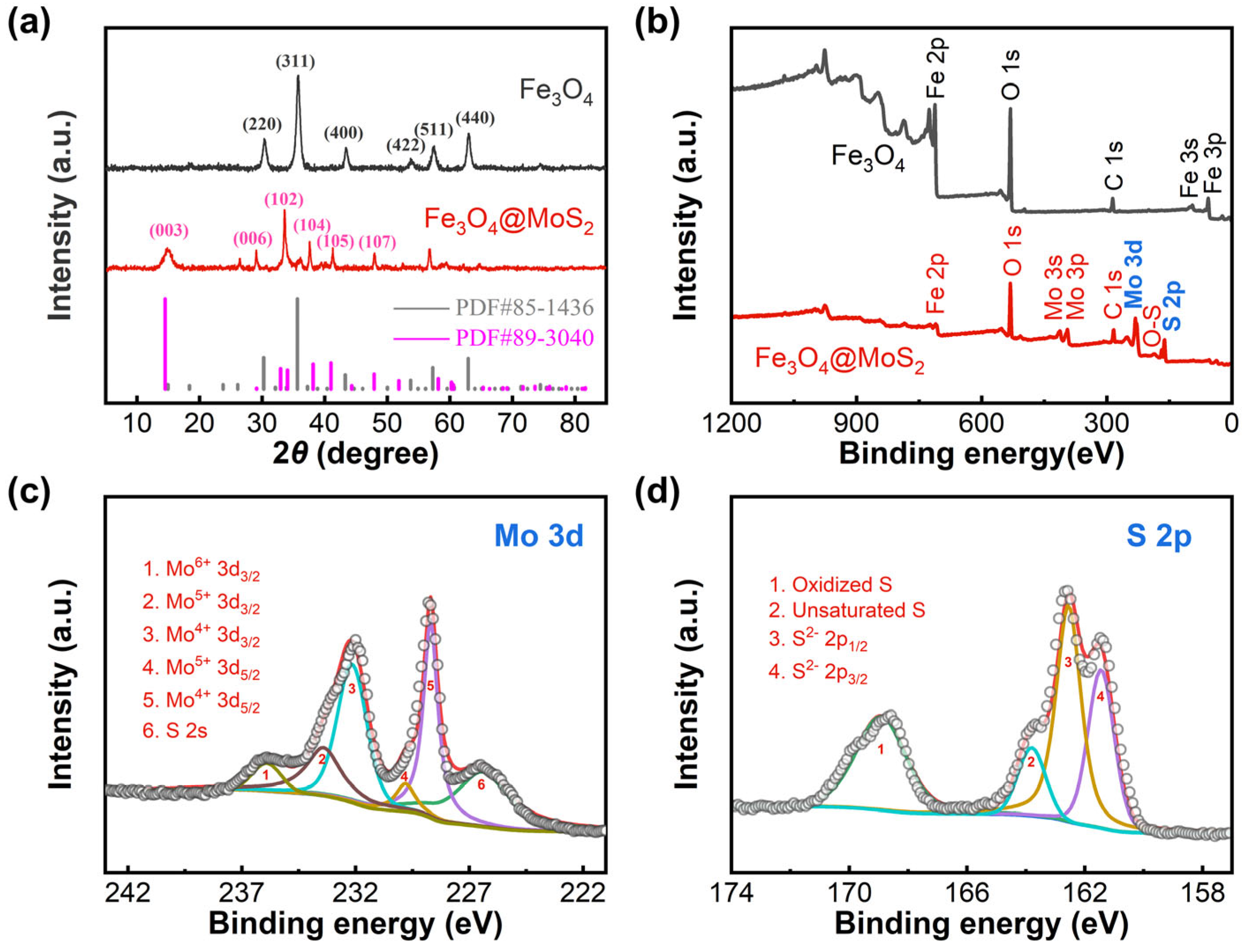
Figure 3.
(a) M–H hysteresis loops of Fe3O4 and Fe3O4@MoS2 measured at 5 K; (b) BET adsorption–desorption curves of Fe3O4 and Fe3O4@MoS2, along with their pore size distributions; (c) adsorption isotherm of rhodamine B by Fe3O4@MoS2 at 298 K, along with the fitted parameters using the Langmuir adsorption isotherm equation, where qe represents the amount of equilibrium adsorption, ce is the equilibrium concentration, qm represents the maximum adsorption capacity, and KL is the Langmuir constant; (d) zeta potential distribution graph of Fe3O4@MoS2 aqueous dispersion at 298 K.
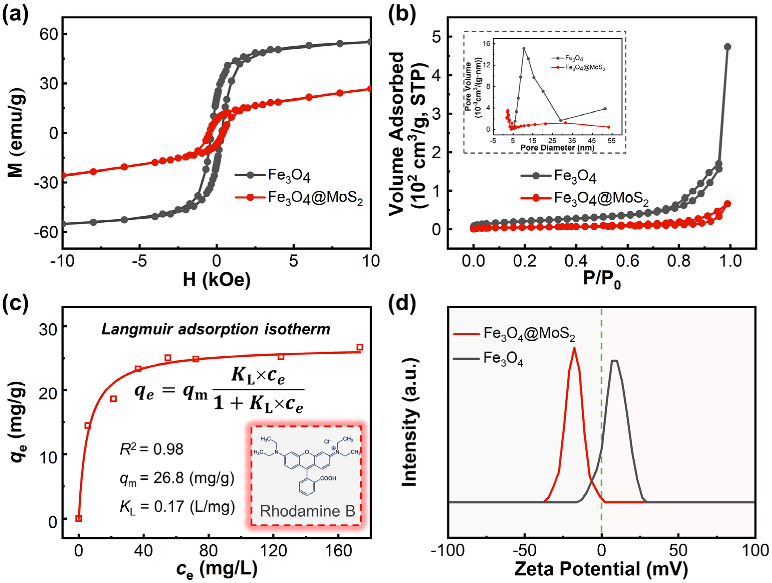
Figure 4.
(a) Piezo-catalytic degradation of rhodamine B over different catalysts under ultrasonic irradiation after an absorption equilibrium; (b) the cycling runs for removal (adsorption for 1 h and piezo-catalytic degradation for 1 h) of rhodamine B over Fe3O4@MoS2; (c) total organic carbon (TOC) removal during the piezo-catalytic degradation of rhodamine B in the presence of Fe3O4@MoS2. The sample at time zero was the solution of rhodamine B that had previously reached adsorption–desorption equilibrium on the Fe3O4@MoS2. All experiments were carried out at 298 K using an initial concentration of 40 mg/L of rhodamine B and 1 g/L of catalyst.
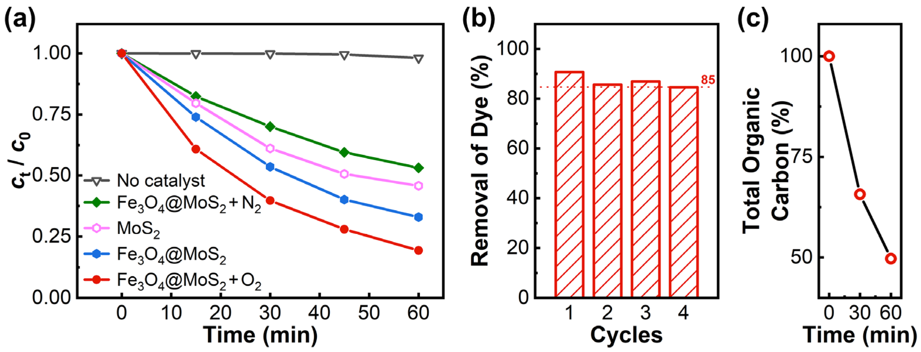
Figure 5.
EPR signals for (a) e∙ trapped with TEMPO, (b) ⋅O2− trapped with DMPO-MeOH, (c) ⋅OH trapped with DMPO, and (d) 1O2 trapped with TEMP, obtained for Fe3O4@MoS2 and corresponding trapping agent systems before and after 3 min of ultrasonic irradiation.
Figure 5.
EPR signals for (a) e∙ trapped with TEMPO, (b) ⋅O2− trapped with DMPO-MeOH, (c) ⋅OH trapped with DMPO, and (d) 1O2 trapped with TEMP, obtained for Fe3O4@MoS2 and corresponding trapping agent systems before and after 3 min of ultrasonic irradiation.

Scheme 2.
A proposed piezo-catalytic mechanism for the degradation of dye in the Fe3O4@MoS2 system under ultrasonic irradiation.
Scheme 2.
A proposed piezo-catalytic mechanism for the degradation of dye in the Fe3O4@MoS2 system under ultrasonic irradiation.

Publisher’s Note: MDPI stays neutral with regard to jurisdictional claims in published maps and institutional affiliations. |
© 2021 by the authors. Licensee MDPI, Basel, Switzerland. This article is an open access article distributed under the terms and conditions of the Creative Commons Attribution (CC BY) license (https://creativecommons.org/licenses/by/4.0/).
Share and Cite
MDPI and ACS Style
Zhou, C.; Liu, W.; Li, H.; Yang, M.; Yang, Z. Separable Magnetic Fe3O4@MoS2 Composite for Adsorption and Piezo-Catalytic Degradation of Dye. Catalysts 2021, 11, 1403. https://doi.org/10.3390/catal11111403
AMA Style
Zhou C, Liu W, Li H, Yang M, Yang Z. Separable Magnetic Fe3O4@MoS2 Composite for Adsorption and Piezo-Catalytic Degradation of Dye. Catalysts. 2021; 11(11):1403. https://doi.org/10.3390/catal11111403
Chicago/Turabian StyleZhou, Chi, Wencheng Liu, Hanqing Li, Miao Yang, and Zixin Yang. 2021. "Separable Magnetic Fe3O4@MoS2 Composite for Adsorption and Piezo-Catalytic Degradation of Dye" Catalysts 11, no. 11: 1403. https://doi.org/10.3390/catal11111403
Note that from the first issue of 2016, this journal uses article numbers instead of page numbers. See further details here.