Article

Hydrophilic Surface Modification of PDMS Microchannel for O/W and W/O/W Emulsions

by
Shazia Bashir
1,2,*,†,
Muhammad Bashir
3,†,
Xavier Casadevall i Solvas
4,
Julia M. Rees
1 and
William B. Zimmerman
5
1
School of Mathematics and Statistics, Hicks Building, University of Sheffield, Sheffield S3 7RH, UK
2
Department of Physics and Applied Mathematics, Pakistan Institute of Engineering and Applied Sciences, Islamabad 45650, Pakistan
3
Department of Physics, COMSATS Institute of Information Technology, Islamabad 45650, Pakistan
4
Department of Chemistry and Applied Biosciences, Institute of Chemical and Bioengineering, ETH Zurich, Ramistrasse 101, 8092 Zurich, Switzerland
5
Department of Chemical and Biological Engineering, University of Sheffield, Sheffield S1 3JD, UK
*
Author to whom correspondence should be addressed.
These authors contributed equally to this work.
Micromachines 2015, 6(10), 1445-1458; https://doi.org/10.3390/mi6101429
Submission received: 21 August 2015 / Revised: 11 September 2015 / Accepted: 16 September 2015 / Published: 29 September 2015
(This article belongs to the Special Issue Droplet Microfluidics: Techniques and Technologies)

Abstract

:
A surface modification method for bonded polydimethylsiloxane (PDMS) microchannels is presented herein. Polymerization of acrylic acid was performed on the surface of a microchannel using an inline atmospheric pressure dielectric barrier microplasma technique. The surface treatment changes the wettability of the microchannel from hydrophobic to hydrophilic. This is a challenging task due to the fast hydrophobic recovery of the PDMS surface after modification. This modification allows the formation of highly monodisperse oil-in-water (O/W) droplets. The generation of water-in-oil-in-water (W/O/W) double emulsions was successfully achieved by connecting in series a hydrophobic microchip with a modified hydrophilic microchip. An original channel blocking technique to pattern the surface wettability of a specific section of a microchip using a viscous liquid comprising a mixture of honey and glycerol, is also presented for generating W/O/W emulsions on a single chip.

1. Introduction

Micrometer-sized emulsions formed in microfluidic systems are of great importance due to their wide applicability in various chemical and biological fields [1,2]. Conventional methods such as high shear homogenizers [3] and rotor/stator systems [4] are usually inadequate for generating high quality monodisperse microemulsions. The resultant large size distributions are problematic for droplet sorting and detection which require size uniformity. Preparation of double emulsions using these methods is even more complex as high shear rates result in coalescence of internal droplets by the external phase. However, with the advent of droplet-based microfluidic systems, several problems that arise in conventional emulsion formulation systems have been resolved. Microdroplets can be prepared and controlled precisely in microfluidic chips so that their formation, splitting, merging, sorting and interrogation can be easily achieved [1,2,5,6,7,8]. In addition to single emulsions, microfluidic platforms are capable of producing highly uniform double (and multiple) emulsions [9,10]. Both types of double emulsions, oil-in-water-in-oil (O/W/O) and water-in-oil-in-water (W/O/W), have great potential for usage in food, cosmetics and pharmaceutical applications [11,12]. W/O/W emulsions, where small water droplets are enclosed within larger oil droplets, dispersed in a continuous water phase, are also strong candidates for applications in drug delivery systems [13,14].
Due to the large surface to volume ratio characteristic of microfluidic devices, the channel surface properties play a vital role in a wide range of applications [15,16]. For droplet-based microfluidics, the wettability of the channel walls determine the type of emulsion that can be obtained: W/O emulsions are obtained in hydrophobic microchannels, while hydrophilic walls produce O/W dispersions. Hydrophobic surface modifications of glass-based microchannels have been carried out in the past to form W/O emulsions. Okushima et al. prepared both W/O/W and O/W/O double emulsions in a channel geometry comprised of two T-junctions fabricated in series on a single glass microchip and also in two-separate T-shaped microchips connected in series [17]. In each of these arrangements, the surface of one of the T-junctions was hydrophobically modified in order to enable the formation of W/O droplets. Although well developed methods exist for the modification of glass microchips, this fabrication process is costly and time consuming. Fabrication of polydimethylsiloxane (PDMS) devices, on the other hand, can be readily achieved using soft lithography techniques. In addition, PDMS is a highly transparent, non-toxic and biocompatible material. Despite its numerous advantages, PDMS is intrinsically hydrophobic, which limits its use for the formation of O/W droplets and for several other applications where the wetting of the microchannel surface with aqueous phases is essential.
Several strategies have been developed to hydrophilically modify PDMS. Plasma oxidation [18,19] renders the PDMS surfaces hydrophilic but this treatment is short lived with hydrophobic recovery initiated after a few minutes/hours. Sol-gel method [20] treatments result in glass-like structures but they are difficult to handle due to their brittle nature and their application is also limited to simple geometries. Layer by layer methods [21,22] result in long term stable hydrophilic coatings but involve carefully controlled multiple steps. Polyethylene oxide (PEO)-modified PDMS chips have been prepared to confer good water wettability to the microfluidic walls, but localization of these “in-bulk” treatments is not possible (and finalization of devices by sealing, i.e., with plasma, is also difficult) [23,24]. Photoinitiated grafting [25,26,27] strategies increase operational costs and become cumbersome in bonded microchannels due to non-uniformity of coatings. Nguyen et al. [28] successfully achieved the extended hydrophilicity of PDMS using extended curing time and temperature, and exposure to vacuum prior to oxygen plasma treatment. Kovach and his co-workers [29] achieved long term hydrophilicity and hemocompatibility of PDMS microchannels using a plasma-assisted polyethylene glycol (PEG) grafting. Barbier et al. [30] deposited plasma polymerized acrylic acid coatings onto unbonded PDMS and implemented for the first time a system to form double emulsions in microchips. This method, though, was performed in vacuum with limitations for implementing on a laboratory scale due its expense. Further details on surface modification methods for PDMS can be found in recent reviews [31,32].
Plasma treatment at atmospheric pressure has recently become a promising technology due its reduced equipment cost and the possibility of in-line and batch system processing [33,34,35]. Evju et al. [36] and Priest et al. [37] successfully generated microplasma in microchannels by embedding electrodes, which add extra cost and complexity to the fabrication process and is also limited to simple geometries. Li and co-workers selectively modified a PDMS microchannel using a low frequency (6–40 kHz) alternating current (AC) discharge without dielectric barrier [38]. However, it is well known that plasma generated at low frequencies (<100 kHz) acts as a conductive medium which is favorable for arc formation between two electrodes. Arc plasma quickly damages the PDMS surface. Therefore, atmospheric pressure plasmas at low frequencies need at least one of the electrodes covered with a dielectric barrier in order to generate a homogenous and stable glow discharge [39,40,41]. In this work, an efficient and long lasting method is demonstrated for localized plasma-initiated acrylic acid polymerization on bonded PDMS microchannels using atmospheric pressure dielectric barrier corona discharge. These coatings were obtained through a single step plasma process and did not need to be regenerated for multiple usages, unlike dynamic coatings.

2. Experimental Methodology
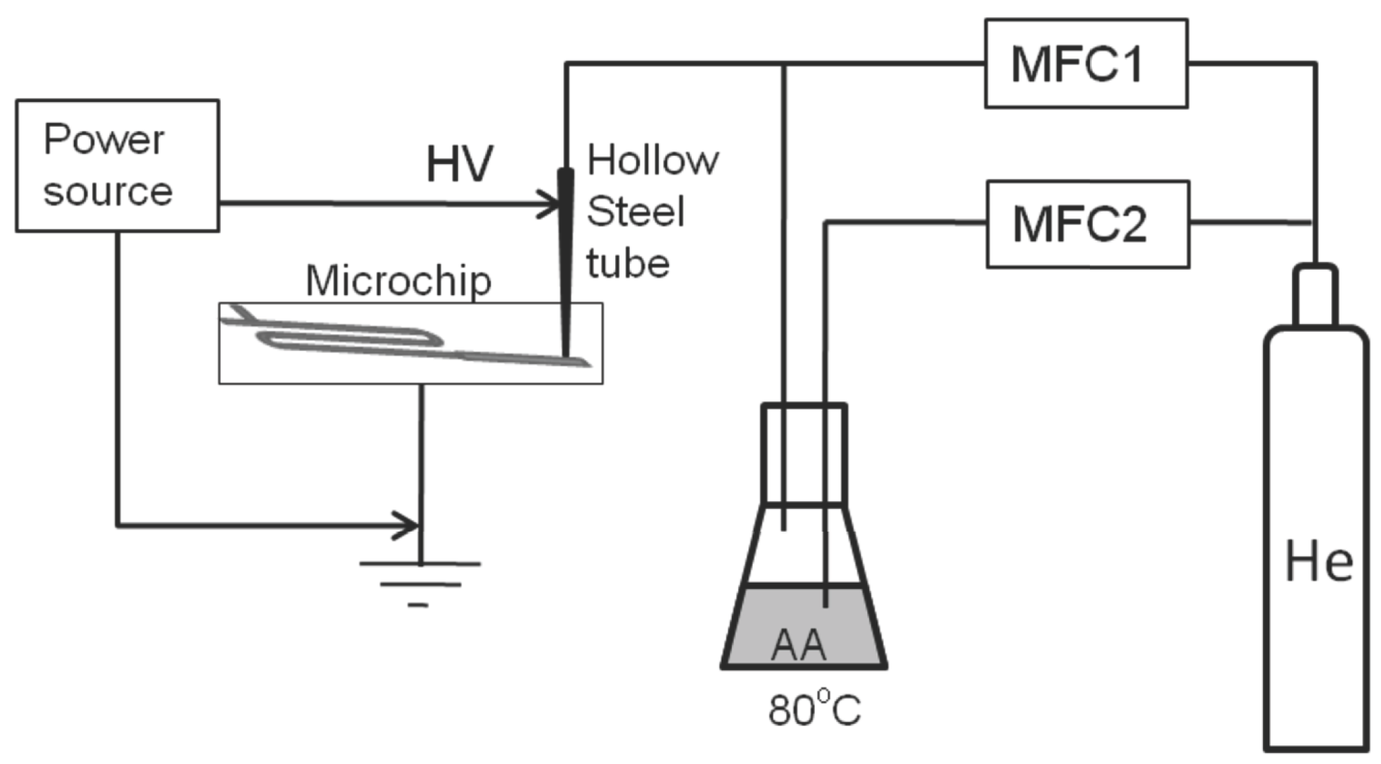
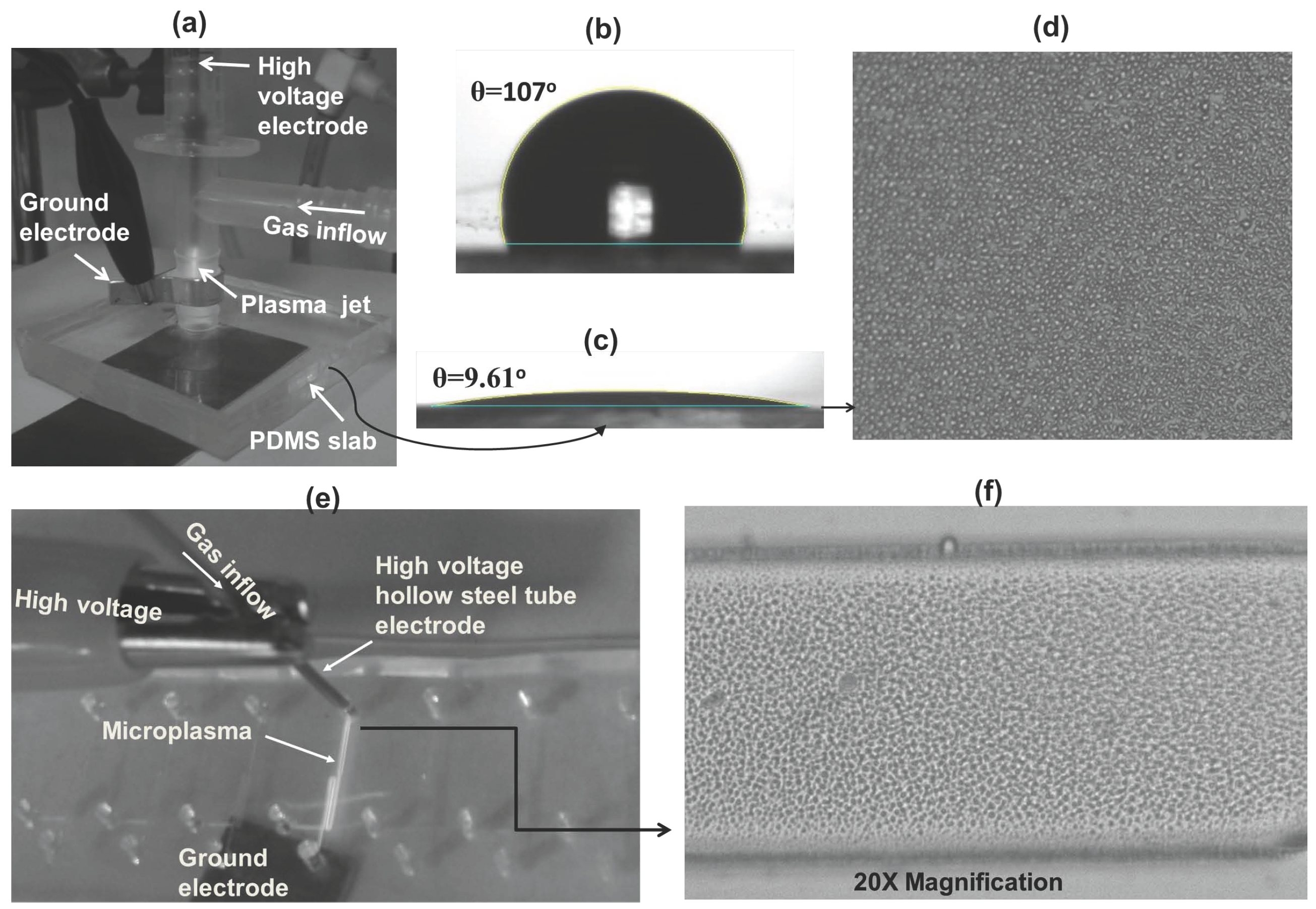
2.1. Coating Setup

The plasma coating system for the microchannel is schematically presented in Figure 1. A steel tube was used as a high voltage thin electrode in order to generate plasma in the microchip. The concentrated high voltage electric field that emanated from the sharp tip of the tube helped to sustain a stable glow discharge in the microchannel. The outer diameter of the tube was chosen to ensure that it fitted into the outlet of the microchannel in order to avoid gas leakage. A copper sheet of thickness 0.6 mm was placed underneath the microchip and used as a ground electrode. The microchip was formed from two PDMS sheets bonded together, the lower sheet acting as a dielectric barrier.
The main flow of helium (He) gas is controlled by a mass flow controller (MFC1). A custom-made gas bubbler was heated at 80 °C in order to vaporize the acrylic acid monomer solution (AA, Sigma-Aldrich, St. Louis, MO, USA, 99% pure). The monomer vapors were introduced into the plasma via the bubbler carried by a secondary He gas flow. The secondary He gas flow rate was controlled by another mass flow controller (MFC2). The upper electrode (steel tube) was connected to a high voltage AC power source having a frequency of 8 kHz (sinusoidal signal). A photograph of the plasma generated in the microchip is shown in Figure 2e.
Figure 1. Schematic of the plasma coating setup for modification of the surface of the polydimethylsiloxane (PDMS) microchip at atmospheric pressure.
Micromachines 06 01429 g001
Figure 2. (a) Surface modification of PDMS substrate with plasma polymerized acylic acid. (b) Deionized (DI) water contact angle with untreated PDMS surface. (c) Water contact angle with plasma polymerized acrylic acid (PPAA) coated PDMS. (d) Charge-coupled device (CCD) image of the coated PPAA film. (e) Plasma polymerization of acrylic acid in microchannel. (f) CCD image of PPAA coated microchannel surface.
Micromachines 06 01429 g002

2.2. Emulsification Setup

Deionized (DI) water was used as the innermost phase in the formation of water-in-oil-in-water emulsions. The middle phase comprised mineral oil containing 4% w/w of Span 80 surfactant. The outermost phase was DI water. In addition to this, fluorinated oil and sunflower oil were also used to form single oil-in-water emulsions. All chemicals were purchased from Sigma-Aldrich except the sunflower oil which was obtained from a local supermarket. Two syringe pumps were used to control the internal and intermediate flow rates in order to form water-in-oil droplets, and an additional syringe pump was used to control the external water phase flow rate to form water-in-oil-in-water double emulsions. A 1280 × 1024 resolution charge-coupled device (CCD) camera (Sensicam QE, PCO Co., Ltd., Didcot, UK) mounted on an inverted microscope (Zeiss Axiovert 100, Carl Zeiss Microscopy, Monument, CO, USA) was used to record images of the single and double emulsions. Images were analyzed using ImageJ (http://rsb.info.nih.gov/ij/) software.

2.3. Plasma Deposition Process

Modifications of internal surfaces within a sealed microfluidic device are potentially promising for achieving a broad range of physicochemical properties of microchannel surfaces that are difficult to attain by wet-chemical techniques or plasma processes in vacuum due to the difficulties of feeding the gas/monomer flow into sealed microchannels [35]. By using a suitable electrode arrangement, as in the current approach, the selective coating of a segment of a microfluidic device can be achieved with a dielectric barrier discharge (DBD) microplasma jet.
The PDMS channel surface was activated in-line via the He plasma for about 1 min. Then the plasma was produced from a mixture of He gas and a gaseous precursor of acrylic acid in order to deposit a thin layer of coating onto the walls of the microchannel. All process parameters such as the flow rates of He and the monomer, and power from the plasma source, were optimized in order to sustain stable discharge and to effectively deposit plasma polymerized acrylic acid (PPAA) film. The He gas flow rate of 400 sccm, monomer flow rate of 20 sccm, plasma power of 7 W and a deposition time of about 6 min were kept constant throughout the experiment until otherwise stated. The deposited thin film was then cross linked by post treatment using He plasma for approximately 2 min. The pre-treatment of the PDMS surface with plasma should not be longer than 1 min otherwise cracks may occur on the surface.
The coating was also applied on a flat PDMS substrate using a DBD plasma jet in order to characterize the plasma polymerized films via a contact angle measurement. The plasma processing parameters such as gas flow rate and discharge power were kept the same as that for microchannel. Plasma was generated in the form of a jet in the main tube of a polypropylene T-connector with an outer diameter of 4.76 mm. The side tube of the T-connector was used to feed the monomer-gas mixture. This setup could safely generate a plasma jet due to the low temperature of the plasma. A central steel wire with a sharp tip was aligned axially using a supporting plastic syringe. This central wire acts as a high voltage electrode and the ring electrode wrapped around the bottom end of the jet pipe is used as a ground electrode. The polypropylene pipe (0.5 mm thick) acts as a dielectric barrier. The configuration for jet plasma is shown in Figure 2a.

3. Results and Discussions

3.1. Contact Angle Measurement

The sessile drop method was used to measure the contact angle of liquid drop with the PPAA coated surface using a First Ten Angstrom (FTA 200) tensiometer. The PDMS slab was placed under the plasma jet for its hydrophilic modification as shown in Figure 2a. Figure 2b,c clearly show that hydrophilic modification of the PDMS surface was achieved using the novel configuration (Figure 2a) as the water contact angle(WCA) decreases from 107° for bare PDMS to 9.16° for coated PDMS. The DBD is a non-thermal plasma, with temperatures typically in the range 40–60 °C, therefore, it is thermally non-aggressive for the PDMS treatment and lowers the risk of damage to the surface.

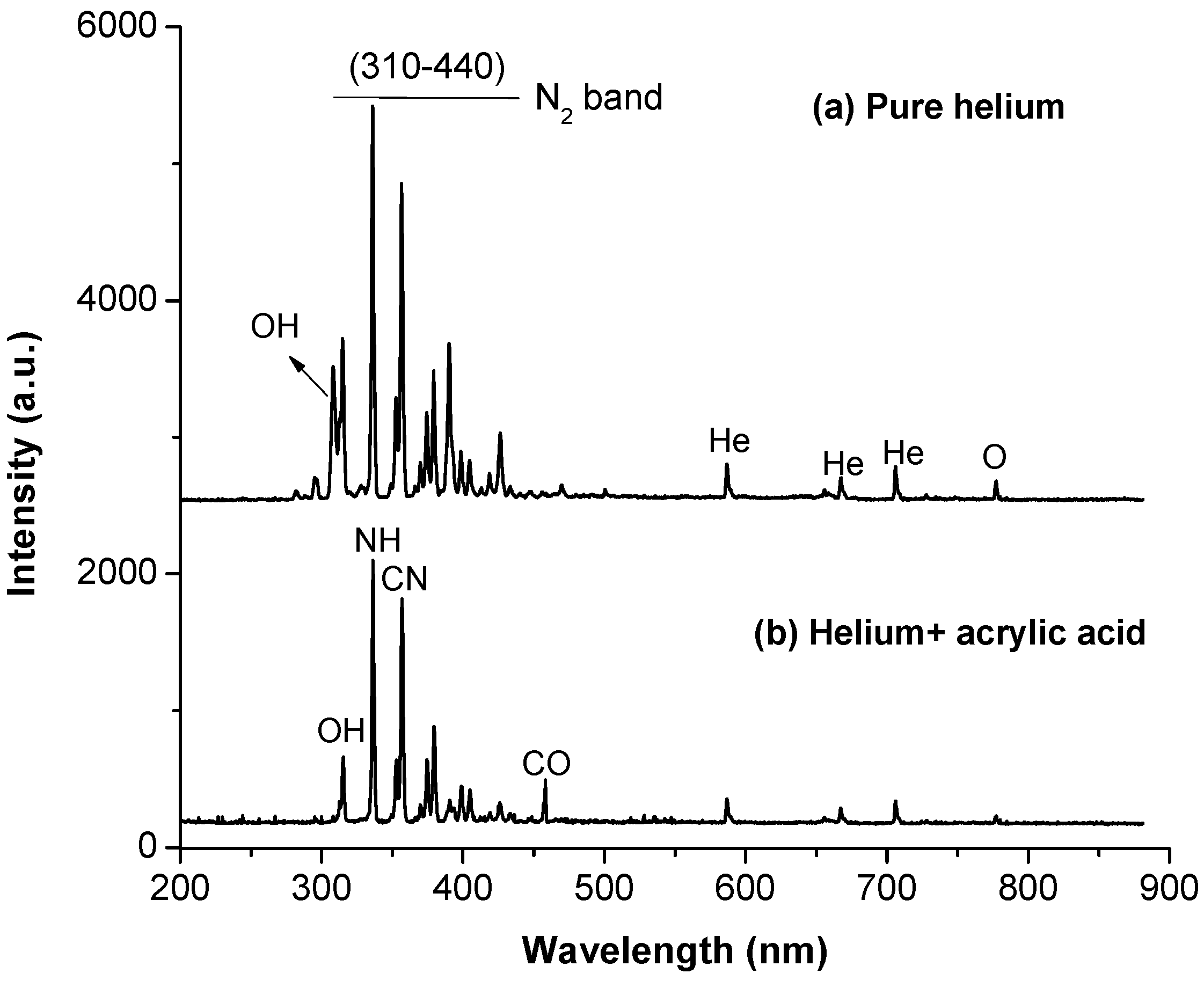
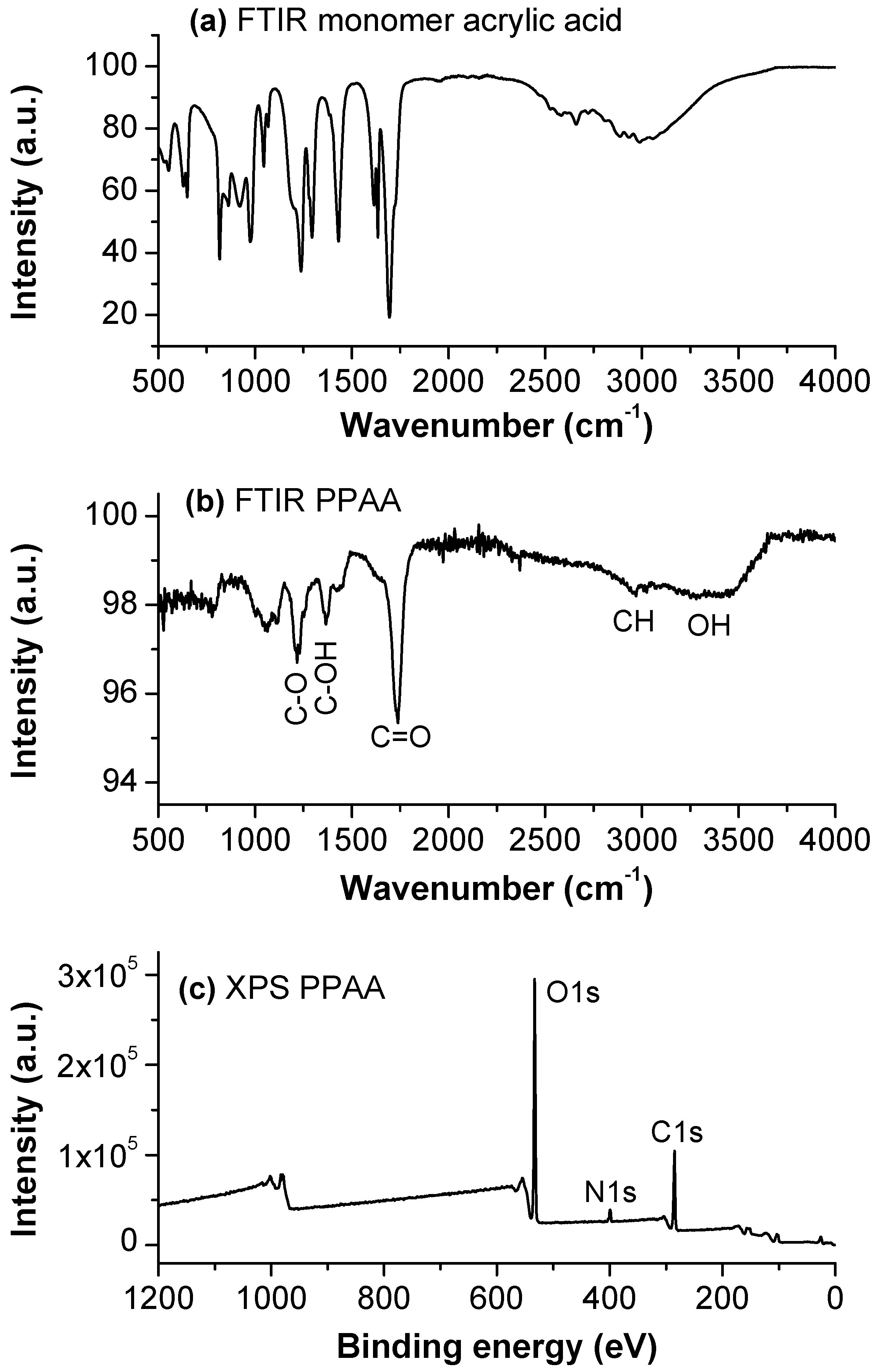
3.2. Plasma and Film Characterization in Microchip

Plasma gas phase characterization was performed by on-chip plasma optical emission spectroscopy (OES) using a USB2000 spectrometer (Ocean Optics, Oxford, UK). A fiber optics cable for collection of the emitted light spectrum was placed directly above the microchannel during the pretreatment with He-plasma as well as during deposition of acrylic acid. Hence, due to optical transparency of PDMS the spectrum was collected without losing any signal. Figure 3b shows the plasma emission spectrum of pure helium along with helium mixed with acrylic acid gaseous monomer. The peaks of the plasma emission spectra of He were identified as OH at 309 nm, N 2 at 315, 337 and 357 nm, N 2 + at 391 nm, He at 380, 587, 668 and 706 nm and, O at 780 nm [42,43,44]. Peaks corresponding to hydroxyl radical, nitrogen and oxygen indicate that the discharge channel is contaminated with air. When acrylic acid was mixed with He in order to achieve deposition in the microchannel, peaks of NH at 337 nm, CN at 359 nm and CO at 457 nm were observed in the emission spectrum. Similar peaks of NH and CN have been reported by Tran et al. [43] during plasma deposition at atmospheric pressure. In this case it was observed that the intensities of the emission spectral lines decreased, which is most likely due to the presence of He metastables involved in breaking the chemical bonds of acrylic acid during additional reactions. Furthermore, spectral lines of NH at 337 nm, and CN at 359 nm indicate that monomer fragmentation takes place during the plasma deposition process.
Figure 3. Plasma emission spectra of (a) pure helium discharge and (b) helium mixed with acrylic acid.
Micromachines 06 01429 g003
A reversible sealing of the microchannel was carried out so that the channel could be disassembled to characterize the coatings. A PDMS sheet with microchannel features on its upside was brought in contact with another fully cured PDMS sheet and kept at room temperature. The reversible bonding can be used for deposition without facing the problem of gas leaking as the coating was performed at atmospheric pressure with outlets open to atmosphere. The reversibly sealed microchannels were opened immediately after deposition for the purpose of characterizing the films.
The chemical structure of the plasma polymerized acrylic acid films was analyzed using Fourier transform infrared (FTIR) spectroscopy. A PerkinElmer (USA) spectrometer (Waltham, MA, USA) equipped with an attenuated total reflectance (ATR) setup at a resolution of 4 cm - 1 was used for FTIR analysis. A scanning range of 4000–400 cm - 1 was selected and an average of 32 scans was performed for each analysis. The spectrum was collected from a coated open microchannel at the circular area (diameter 2 mm) of the outlet. The bands in the FTIR spectrum were identified using data previously reported in the literature [45,46]. Figure 4a,b show the spectra of monomer and polymer acrylic acid respectively. The spectrum of the monomer shows multiple and well resolved peaks compared to the broad bands that appear in the plasma polymer. As plasma is an effective source of different types of reactive species, a number of close absorption peaks of monomer overlap forming a single wide band in the plasma polymer [35]. The comparison of the spectra of monomer and polymer provide evidence that acrylic acid has actually been polymerized and deposited at the PDMS surface. Figure 4b clearly shows that the spectrum of the film polymerized at low plasma power (7 W) exhibits a dominant absorption band at 1724 cm - 1 which can be assigned to stretching vibration of the C=O group. The spectrum contains a very broad band ranging from 3600 to 2400 cm - 1 which can be assigned to the stretching vibrations of the hydroxyl group OH. A smaller peak at 3300 cm - 1 which can be attributed to stretching vibrations of the CH bond is also superimposed on a broad peak of OH. At low wave numbers, two other significant bands appeared at 1360 and 1220 cm - 1 which can be assigned to the stretching vibrations of C–OH and C–O groups respectively [46]. Hence, in view of the above mentioned FTIR data, it is concluded that a significant amount of carboxylic acid group is present at the surface of the deposit in the microchannel.
Figure 4. Fourier transform infrared (FTIR) absorption spectra of (a) acrylic acid monomer and (b) plasma polymerized acrylic acid deposited in the microchannel. (c) X-ray photoelectron spectroscopy (XPS) wide scan spectrum of plasma polymerized acrylic acid recorded in the microchannel.
Micromachines 06 01429 g004
X-ray photoelectron spectroscopy (XPS) is a powerful technique for characterizing ultra thin films as it gives signals from the upper 10 nm layer of the surface. It gives reliable information about the film chemistry by quantifying the elemental composition (e.g., C, N and O, etc.) of the surface. XPS analysis was performed using a Kratos Axis Ultra DLD photoelectron spectrometer equipped with a monochromatic Al-K α X-ray source operated at a power of 150 W. XPS scans were performed in the coated open microchannel at the surface of outlet. An elliptical area of 300 × 700 μm 2 was selected on the surface. Figure 4c shows the XPS survey spectrum of PPAA that was recorded at 160 eV pass energy with a 1 eV step width. The assignments to peaks in the XPS spectrum are made using the previously reported literature [46]. The XPS analysis shows that the plasma polymer deposited at a power of 7 W contains 32.79% oxygen, 64.71% carbon and 2.50% nitrogen, whilst the monomer is composed of 33.3% carbon and 22.2% oxygen. It shows that the carbon content of the film is decreased, and that the amount of oxygen is increased after deposition. The increase in the oxygen content can be attributed to the incorporation of oxygen from the ambient air during atmospheric pressure deposition. It may react after deposition with unstable surface radicals during sample storage and transportation [47]. The trace of nitrogen on PPAA coatings is also most likely due to the interaction of nitrogen from ambient air with discharge occuring during the deposition process. The results of XPS analysis indicate that a significant number of carbon and oxygen atoms are present, corroborating results obtained using FTIR spectroscopy. Moreover, the absence of background silicon signals in the survey spectrum (Figure 4c) indicates that the thickness of the coating was greater than 10 nm. Also, it was clear from the FTIR spectrum (Figure 4b) that the coating has a substantial thickness as the absorption depth of IR beam is typically 1 μm into the surface of the film.

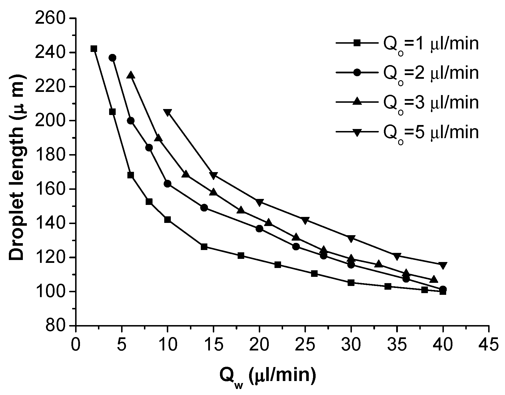
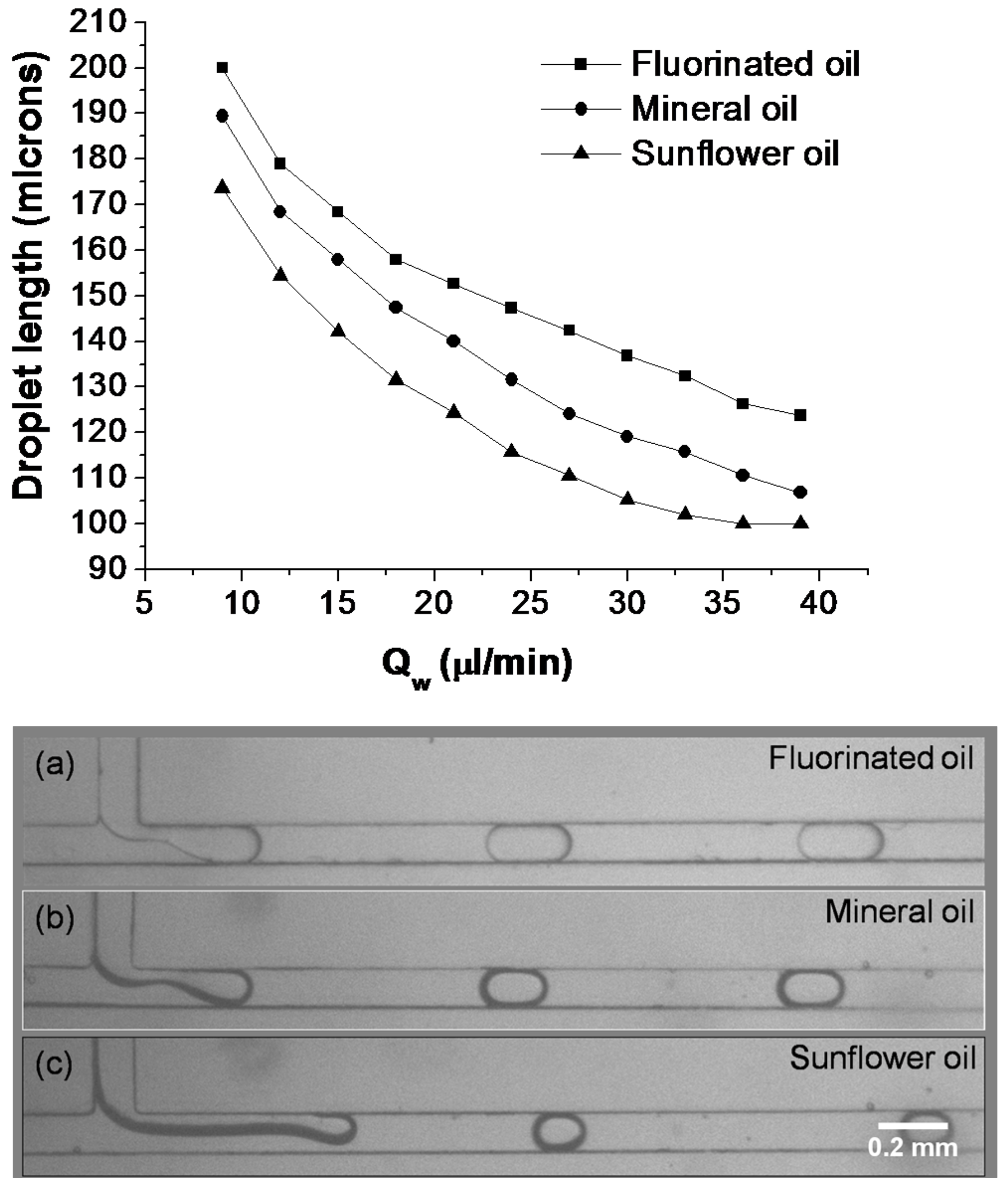
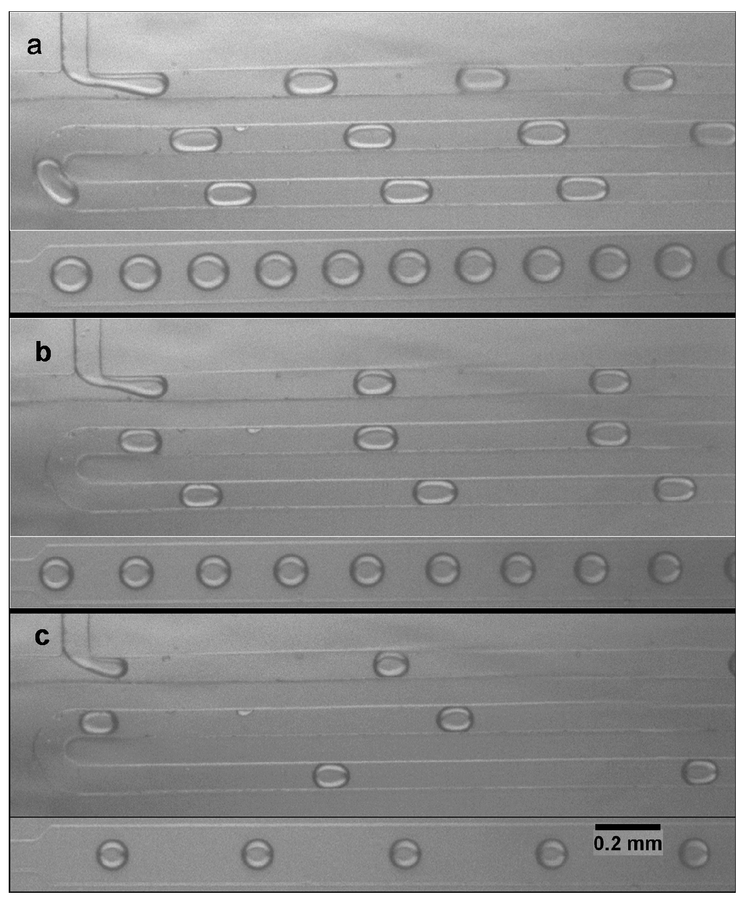
3.3. Formation of Oil-in-Water Microdroplets

The oil-in-water emulsions were successfully prepared in a PDMS microfluidic device after the hydrophilic modification of the channel surface. As a result of this modification, water preferentially wetted the channel walls instead of oil, and consequently the formation of oil droplets in water was possible. Droplets of oil-in-water were continuously produced in modified microchips for a wide range of flow rates and were observed for about 4 h. During this observation period the film was stable and no degradation was noticed. The same device was connected in series with a hydrophobic device to produce double emulsions and was reused several times over a 4 week period without any change in its hydrophilic character.
Microfluidic droplet formation experiments were performed using a continuous phase of deionized water and a dispersed phase of mineral oil. Figure 5 is a snapshot of monodisperse mineral oil droplets formed at a constant flow rate of 1 μL/min and water flow rates of 4, 8 and 16 μL/min respectively. The lengths of mineral oil droplets corresponding to a range of water flow rates from 1 to 40 μL/min are presented in Figure 6. The droplet size decreased with increasing flow rates of the continuous water phase at a specific flow rate of the dispersed oil phase. The droplet size increases with increasing flow rate of the disperse phase which corroborates previous findings [48,49,50]. Figure 6 confirms that the oil droplet size was precisely controlled by changing the water flow rate. Uniformity of the droplet size was reproducible under different experimental conditions. Furthermore, droplets of fluorinated oil (FC-40) with a low viscosity of 3.4 mPa·s and droplets of sunflower oil with a viscosity of 48.98 mPa·s, which is almost double that of the mineral oil, were also formed in water and compared with those of mineral oil at a fixed oil phase flow rate of 3 μL/min as shown in Figure 7. It can be seen that over the whole range of continuous phase flow rates considered, the oil droplet length decreased as the viscosity of the dispersed oil phase was increased. The viscosity was measured using a viscometer with a similar procedure to that described in Bashir et al. [16].
Figure 5. Snapshots of mineral oil droplet formation in water in a hydrophilic PDMS device, (a) Q o = 1 μL/min, Q w = 4 μL/min, (b) Q o = 1 μL/min, Q w = 8 μL/min, (c) Q o = 1 μL/min and Q w = 16 μL/min.
Micromachines 06 01429 g005
Figure 6. Influence of two phase flow rates on length of mineral oil droplets utilizing hydrophilic PDMS microchannel.
Micromachines 06 01429 g006
Figure 7. Effect of water phase flow rates on length of droplets generated using three different oils with varying viscosities at a fixed flow rate of 3 μL/min. Snapshots of the droplets formed using (a) fluorinated oil (μ = 3.4 mPa·s), (b) mineral oil (μ = 24 mPa·s) and (c) sunflower oil (48.98 mPa·s).
Micromachines 06 01429 g007

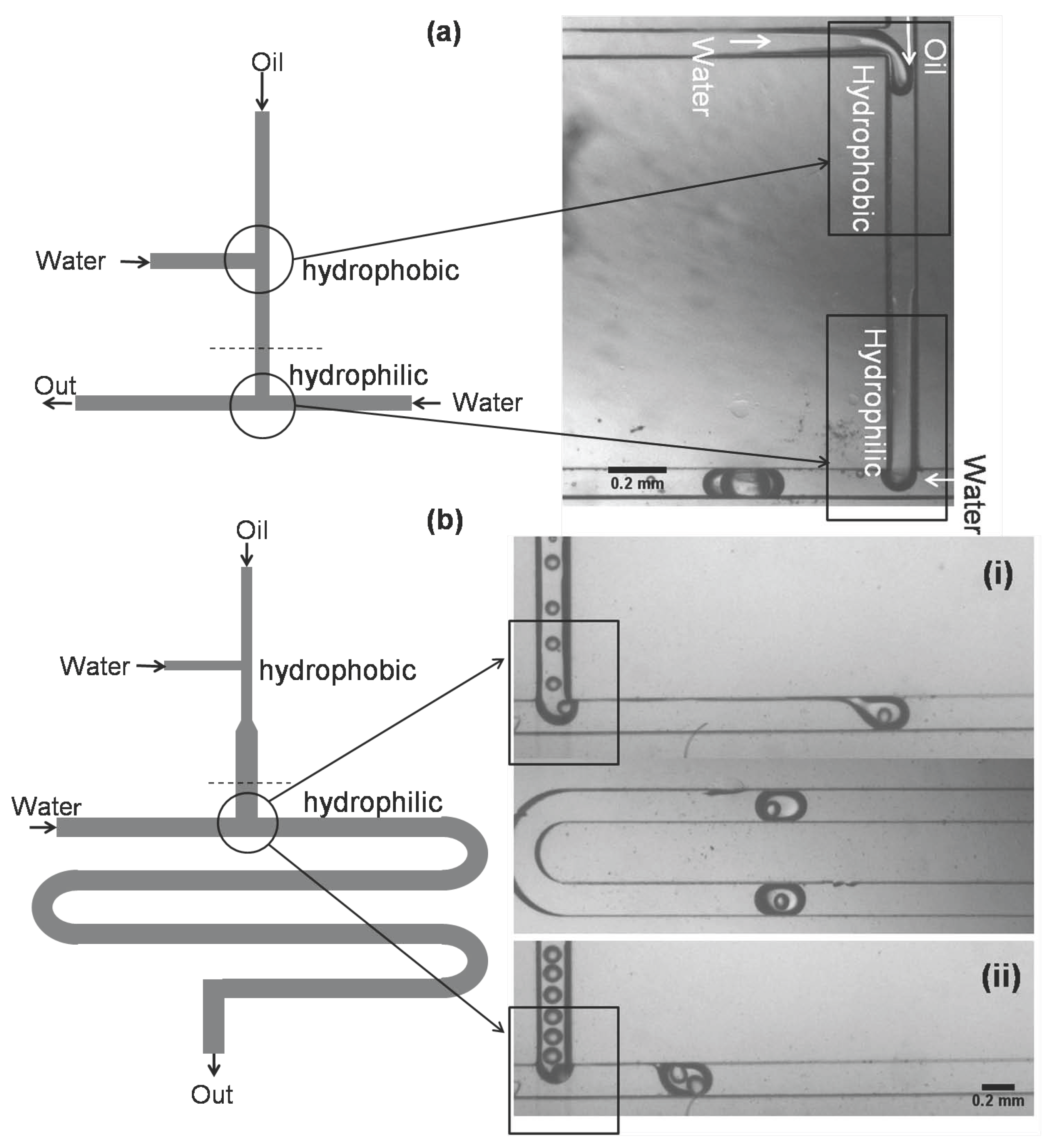
3.4. Microfluidic System for Double Emulsions

The formation of a double emulsion is a two step process. In the first step, the aqueous phase acts as the dispersed phase and is sheared off by the carrier oil phase to form a water-in-oil emulsion. In the second step, an oil stream containing water droplets acts as the dispersed phase and is sheared off by another continuous aqueous phase to form a water-in-oil-in-water double emulsion. This two step double emulsion formation process can be performed via a single chip module or by a double chip module. The generation of a double emulsion in a single chip module is usually difficult to achieve by means of surface modification. In order to form a double emulsion, either part of the hydrophilic device needs to be modified to become hydrophobic, or part of the hydrophobic device needs to be hydrophilically modified. However, in a two chip module, only one of the microchips connected in series needs to be modified. This results in a flexible double emulsion system in terms of implementation for different types of configuration and their surface modification [17,51].

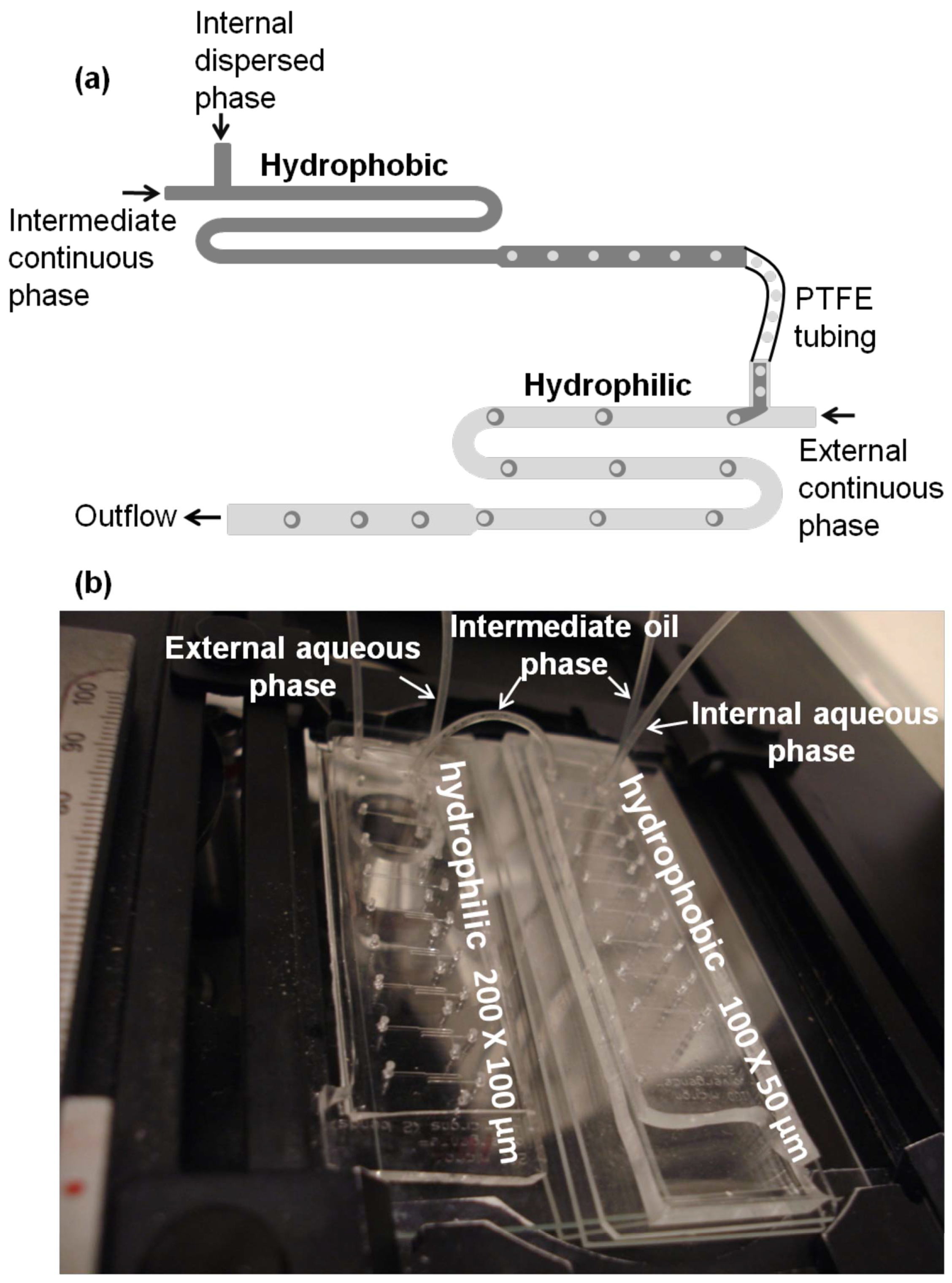
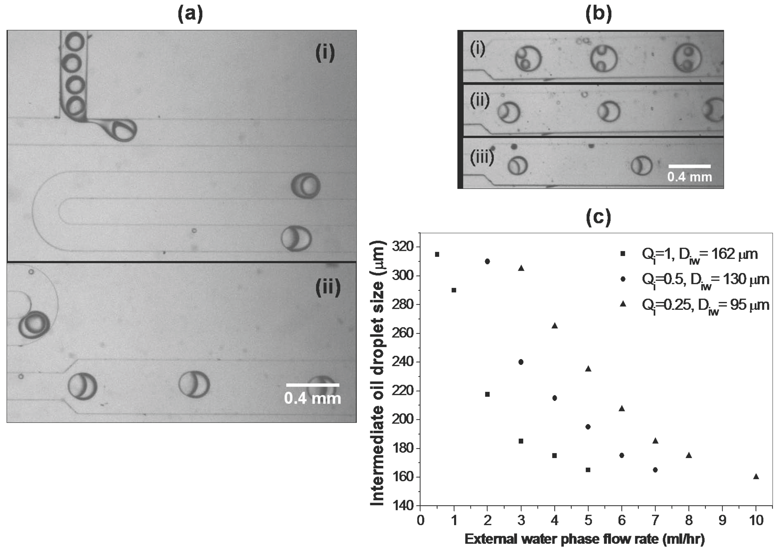
3.4.1. Two Microchip Module

A schematic diagram of the double emulsion process using the two-microchip module is illustrated in Figure 8a. Two separate T-shaped microfluidic PDMS devices were used to generate double emulsions. Both microfluidic chips consisted of the same T-shaped geometry with rectangular cross section channels. The generation of a water-in-oil emulsion in the first microchip results from the natural hydrophobicity of the channel. This microchip has a channel cross sectional area of 100 × 50 μm 2 . DI water was used as the dispersed phase and mineral oil containing 4% of Span 80 surfactant was used as the continuous phase. The second microchip contains a channel of 200 × 100 μm 2 cross-sectional area such that the aspect ratio remains the same as that of the first microchip. This microchip was made hydrophilic using the aforementioned localized microplasma polymerization technique in order to generate oil-in-water emulsions. In this step, mineral oil containing water droplets from the first microchip was used as the dispersed phase and DI water was used as an external carrier phase. The droplets of water generated in the first microchip, along with the carrier oil, were transported into the second microchip via a small piece of PTFE tubing to form a water-in-oil-in-water double emulsion. The first microchip was elevated with respect to the second microchip in order to avoid droplets being pushed back by the external carrier phase into the second microchip as shown in Figure 8b. Figure 9a shows images of the formation of a double emulsion in the two-microchip module. The internal water droplet size in the hydrophobic microchip can be controlled by altering the ratio of flow rates of the internal water phase to that of the middle oil phase. Figure 9c shows the effect of the external water phase flow rate in the second microchip on intermediate oil droplet sizes for different flow rate ratios. We can write Q i = Q i w Q m o is the flow rate of the internal dispersed water phase and Q m o is the middle oil phase flow rate. The oil droplet sizes decrease with the external water phase flow rate but the internal water droplet size D i w is not affected by any changes made to the external flow conditions at a constant flow rate ratio Q i . Similar observations were also made in previously reported double emulsion data obtained using a two-chip module by [17], where they used a silane-coupling agent to modify one of the hydrophilic glass microchips to become hydrophobic. This suggests that the optimization of the flow rate ratio Q i in a water-in-oil emulsion is necessary to obtain the appropriate droplet size that could be enclosed in an oil droplet in order to achieve regular encapsulation each time in the second T-junction device. It was observed that the regular encapsulation of water droplets within the middle oil droplets was obtained for Q i = 1, Q i = 0.5 and Q i = 0.25. In the cases where Q i = 1 and Q i = 0.5, single water droplet encapsulation within the oil drop was obtained, whilst in the case of Q i = 0.25 two water droplets were enclosed within a single oil droplet as shown in Figure 9b were obtained. The existence of an external aqueous phase flow rate beyond which each oil droplet encloses a single aqueous droplet is probable, e.g., in case of Q i = 0.5 a single droplet encapsulation in each oil droplet was observed when Q e w was around 50 μL/min (3 mL/h) and this scenario persisted until the flow rate reached 117 μL/min. At Q e w = 117 μL/min (7 mL/h), the oil droplet size became approximately equal to the size of the encased water droplet, which is the minimum possible size for an encased droplet to exist. Beyond this external flow rate the probability of water droplet encapsulation in oil droplets decreased. In this regime most of the oil droplets were observed to be generated without encapsulating a water droplet and eventually at higher external flow rates the number of encapsulating droplets became zero as the droplets started to push back into the first microchip. Therefore, the external phase flow rate needs to be carefully optimized in order to generate double emulsions where each oil droplet contains a single water droplet. Double emulsion experiments were repeated three times in order to assess the reproducibility of the results.
Figure 8. (a) Schematic diagram of the two-microchip module. (b) Snapshot of the formation of double emulsion process in two-microchip module.
Micromachines 06 01429 g008
Figure 9. Snapshots of a water-in-oil-in-water emulsion generated using a hydrophilic PDMS device at (a-i) T-junction with Q i w = 1 μL/min, Q m o = 2 μL/min, Q e w = 60 μL/min and (a-ii) flowing down in the diverging section of the device. (b) Snapshots of encapsulated droplets in diverging section. (c) Intermediate oil droplet size corresponding to different flow rates of external water phase flow rates at different flow rate ratios Q i . Internal water droplet sizes are mentioned along with Q i .
Micromachines 06 01429 g009

3.4.2. Single microchip module

A single microchip containing two T-junction microchannels in cascade is shown in Figure 10. A selective modification of the microchip was made using a plasma polymerization technique. Honey containing 20% w/w glycerol was injected from the oil inlet and was monitored through the microscope as it started to fill the channel. Glycerol was added to the honey in order to prevent solidification in the microchannel. When the channel was filled to the point just above the second T-junction indicated by the dotted line, the flow was stopped. As honey is a highly viscous liquid it never flowed past the junction. After blocking the hydrophobic portion of the channel, plasma polymerization of acrylic acid was carried out on the desired section of the microchip. Plasma was generated using the aforementioned microjet technique via an external water phase inlet. As the discharge power was low, the temperature of the blocked channel did not increase, thus avoiding any decrease in the viscosity of the honey. Thus, only the regions of the channel surfaces that were exposed to the plasma became hydrophilic. The hydrophilic microchannel was the second channel in series which was preferentially wetted by water over oil as shown in Figure 10. This hydrophilic modification resulted in emulsification of oil droplets in water at the second T-junction of the microchip. Once the oil droplet formation in water was ensured, formation of a double emulsion was achieved by use of both the hydrophobic and hydrophilic junctions of the same microfluidic chip. Two types of configuration were employed in order to perform the double emulsion experiments as shown in Figure 10. In the first geometry considered, both the upper and lower parts of the microchannel were of the same dimensions (100 μm wide). A single internal water droplet encapsulation occurred in an intermediate oil plug as shown in Figure 10a. However, in second type of geometry where the hydrophilic section of the microchip was wider (200 μm) than the hydrophobic section (100 μm), the number of internal water droplets could be altered by varying the flow rate ratio Q i = Q i w Q m o whilst keeping the external water phase flow rate, Q e w , fixed as shown in Figure 10b.
Figure 10. Double emulsion in single chip module: (a) Water-in-oil-in-water emulsion in a double T-junction comprising channels of equal dimensions. (b) Water-in-oil-in-water emulsion in double T-junction with different dimensions. Water droplet encapsulation in an oil droplet/plug: (i) Q i w : Q m o : Q e w = 1:4:200, (ii) Q i w : Q m o : Q e w = 1:2:200.
Micromachines 06 01429 g010

4. Conclusions

A single step inline microchannel surface modification method based on plasma polymerization of acrylic acid has been developed for the stable production of on-chip double emulsions. The FTIR spectrum of the polymer indicated the high retention of the carboxylic acid group at the surface which helped to enhance the hydrophilicity of the film. The emission of the spectral lines NH, CN and CO indicated that the monomers were fragmented during plasma polymerization in the microchannel. Highly monodisperse oil-in-water and water-in-oil-in-water emulsions in hydrophilically modified PDMS microdevices were successfully prepared. Droplets of different types of oil were used to form single oil-in-water emulsions and the results were compared in order to see the effect of viscosity on droplet size. The oil droplet size were decreased using an oil with a relatively high viscosity over the entire range of water flow rates considered. In W/O/W emulsions, the intermediate oil droplet size was controlled by varying the external flow rate conditions and the size of droplet enclosed in an intermediate oil droplet was altered by changing the flow rate ratio at the hydrophobic junction. The plasma-based surface modification method proved to be robust, and avoided the use of surfactants in the continuous phase. The original dimensions of the microchannel were preserved due to ultra thin layer of the polymerized films. The films are also transparent therefore they do not affect the optical transparency of microchips.

Acknowledgments

Authors acknowledge support from the EPSRC grant EP/E01867X/1 (Bridging the Gap between Mathematics, ICT and Engineering Research) at Sheffield.

Conflicts of Interest

The authors declare no conflict of interest.

References

  1. Gunther, A.; Jensenb, K.F. Multiphase microfluidics: from flow characteristics to chemical and materials synthesis. Lab Chip 2006, 6, 1487–1503. [Google Scholar] [CrossRef]
  2. Casadevall i Solvas, X.; de Mello, A. Droplet microfluidics: Recent developments and future applications. Chem. Commun. 2011, 47, 1936–1942. [Google Scholar] [CrossRef] [PubMed]
  3. McClements, J.D. Food Emulsions: Principle, Practices and Techniques; CRC Press: Boca Raton, FL, USA, 1999. [Google Scholar]
  4. Urban, K.; Wagner, G.; Schaffner, D.; Roglin, D.; Ulrich, J. Rotor-stator and disc systems for emulsification processes. Chem. Eng. Technol. 2006, 29, 24–31. [Google Scholar]
  5. Seemann, R.; Brinkmann, M.; Pfohl, T.; Herminghaus, S. Droplet based microfluidics. Rep. Prog. Phys. 2012, 75, 016601. [Google Scholar] [CrossRef]
  6. Song, H.; Chen, D.L.; Ismagilov, R.F. Reactions in droplets in microfluidic channels. Angew. Chem. Int. Ed. 2006, 45, 7336–7356. [Google Scholar] [CrossRef] [PubMed]
  7. Belder, D. Microfluidics with droplets. Angew. Chem. Int. Ed. 2005, 44, 3521–3522. [Google Scholar] [CrossRef] [PubMed]
  8. Casadevall i Solvas, X.; Niu, X.; Leeper, K.; Cho, S.; Chang, S.I.k.; Edel, J.B.; de Mello, A.J. Fluorescence detection methods for microfluidic droplet platforms. J. Vis. Exp. 2011, 58, 1–7. [Google Scholar]
  9. Utada, A.S.; Lorenceau, E.; Link, D.R.; Kaplan, P.D.; Stone, H.A.; Weitz, D.A. Monodisperse double emulsions generated from a microcapillary. Science 2005, 308, 537–541. [Google Scholar] [CrossRef] [PubMed]
  10. Shah, R.K.; Shum, H.C.; Rowat, A.C.; Lee, D.; Agresti, J.J.; Utada, A.S.; Chu, L.Y.; Kim, J.W.; Nieves, A.F.; Martinez, C.J.; et al. Designer emulsions using microfluidics. Mater. Today 2008, 11, 18–27. [Google Scholar] [CrossRef]
  11. Matsumoto, S.; Kita, Y.; Yonezawa, D. An attempt at preparing water-in-oil-in-water multiple phase emulsions. J. Colloid. Interface. Sci. 1976, 57, 353–361. [Google Scholar] [CrossRef]
  12. De Luca, M.; Rocha-Filho, P.; Grossiord, J.L.; Rabaron, A.; Vaution, C.; Seiller, M. Les émulsions multiples. Int. J. Cosmetic. Sci. 1991, 13, 1–21. [Google Scholar] [CrossRef] [PubMed]
  13. Shum, H.C.; Kim, J.W.; Weitz, D.A. Microfluidic fabrication of monodisperse biocompatible and biodegradable polymersomes with controlled permeability. J. Am. Chem. Soc. 2008, 130, 9543–9549. [Google Scholar] [CrossRef]
  14. Shum, H.C.; Lee, D.; Yoon, I.; Kodger, T.; Weitz, D.A. Double emulsion templated monodisperse phospholipid vesicles. Langmuir 2008, 24, 7651–7653. [Google Scholar] [CrossRef] [PubMed]
  15. Bashir, S.; Rees, J.M.; Zimmerman, W.B. Simulations of microfluidic droplet formation using the two-phase level set method. Chem. Eng. Sci. 2011, 66, 4733–4741. [Google Scholar] [CrossRef]
  16. Bashir, S.; Casadevall i Solvas, X.; Bashir, M.; Rees, J.M.; Zimmerman, W.B. Dynamic wetting in microfluidic droplet formation. BioChip J. 2014, 8, 122–128. [Google Scholar] [CrossRef]
  17. Okushima, S.; Nisisako, T.; Tori, T.; Higuchi, T. Controlled production of monodisperse double emulsions by two-step droplet breakup in microfluidic devices. Langmuir 2004, 20, 9905–9908. [Google Scholar] [CrossRef] [PubMed]
  18. Honest Makamba, H.; Kim, J.H.; Park, N.; Hahn, J.H. Surface modification of poly(dimethylsiloxane) microchannels. Electrophoresis 2003, 24, 3607–3619. [Google Scholar] [CrossRef] [PubMed]
  19. Fritz, J.L.; Owen, M.J.; Adhesion, J. Hydrophobic recovery of plasma-treated polydimethylsiloxane. J. Adhesion 1995, 54, 33–45. [Google Scholar] [CrossRef]
  20. Roman, G.T.; Hlaus, T.; Bass, K.J.; Seelhammer, T.G.; Culbertson, C.T. Sol-gel modified poly(dimethylsiloxane) microfluidic devices with high electroosmotic mobilities and hydrophilic channel wall characteristics. Anal. Chem. 2005, 77, 1414–1422. [Google Scholar] [CrossRef] [PubMed]
  21. Bauer, W.A.C.; Fischlechner, M.; Abell, C.; Huck, W.T.S. Hydrophilic PDMS microchannels for high-throughput formation of oil-in-water microdroplets and water-in-oil-in-water double emulsions. Lab Chip 2010, 10, 1814–1819. [Google Scholar] [CrossRef] [PubMed]
  22. Ji, J.; Zhao, Y.; Guo, L.; Liu, B.; Jib, C.; Yang, P. Interfacial organic synthesis in a simple droplet-based microfluidic system. Lab Chip 2012, 12, 1373–1377. [Google Scholar] [CrossRef] [PubMed]
  23. Delamarche, E.; Donzel, C.; Kamounah, F.S.; Wolf, H.; Geissler, M.; Stutz, R.; Winkel, P.S.; Michel, B.; Mathieu, H.J.; Schaumburg, K. Microcontact printing using poly(dimethylsiloxane) stamps hydrophilized by poly(ethylene oxide) silanes. Langmuir 2003, 19, 8749–8758. [Google Scholar] [CrossRef]
  24. Yao, M.; Fang, J. Hydrophilic PEO-PDMS for microfluidic applications. J. Micromech. Microeng. 2012, 22, 025012. [Google Scholar] [CrossRef]
  25. Seo, M.; Paquet, C.; Nie, Z.; Xua, S.; Kumacheva, E. Microfluidic consecutive flow-focusing droplet generators. Soft. Matter. 2007, 3, 986–992. [Google Scholar] [CrossRef]
  26. Rohr, T.; Ogletree, D.F.; Svec, F.; Frechet, J.M.J. Surface functionalization of thermoplastic ploymers for the fabrication of microfluidics devices by photoinitiated grafting. Adv. Funct. Mater. 2003, 13, 264–270. [Google Scholar] [CrossRef]
  27. Hu, S.; Ren, S.; Bachman, M.; Sims, C.E.; Li, G.P.; Allbritton, N. Surface modification of poly(dimethylsiloxane) microfluidic devices by ultraviolet polymer grafting. Anal. Chem. 2002, 74, 4117–4123. [Google Scholar] [CrossRef] [PubMed]
  28. Nguyen, L.; Hang, M.; Wang, W.; Tian, Y.; Wang, L.; McCarthy, T.; Chen, W. Simple and improved approaches to long-lasting, hydrophilic silicones derived from commercially available precursors. Appl. Mater. Interfaces 2014, 6, 22876–22883. [Google Scholar] [CrossRef] [PubMed]
  29. Kovach, K.; Capadona, J.; Sen Gupta, A.; Potkay, J. The effects of PEG-based surface modification of PDMS microchannels on long-term hemocompatibility. J. Biomed. Mater. Res. 2014, 102, 4195–4205. [Google Scholar] [CrossRef] [PubMed]
  30. Barbier, V.; Tatoulian, M.; Tori, T.; Arefi-Khonsari, F.; Ajdari, A.; Tabeling, P. Stable modification of PDMS surface properties by plasma polymerization: Application to the formation of double Emulsions in microfluidic systems. Langmuir 2006, 22, 5230–5232. [Google Scholar] [CrossRef] [PubMed]
  31. Wong, T.; Ho, C.M. Surface molecular property modifications for poly(dimethylsiloxane) (PDMS) based microfluidic devices. Microfluid. Nanofluid. 2009, 7, 291–306. [Google Scholar] [CrossRef] [PubMed]
  32. Zhou, J.; Khodakov, D.A.; Ellis, A.V.; Voelcker, N.H. Surface modification for PDMS-based microfluidic devices. Electrophoresis 2012, 33, 89–104. [Google Scholar] [CrossRef]
  33. Bashir, M.; Bashir, S. Hydrophobic–hydrophilic character of hexamethyldisiloxane films polymerized by atmospheric pressure plasma jet. Plasma Chem. Plasma Process. 2015, 35, 739–755. [Google Scholar] [CrossRef]
  34. Tendero, C.; Tixier, C.; Tristant, P.; Desmaison, J.; Leprince, P. Atmospheric pressure plasmas: A review. Spectrochim. Acta Part B 2006, 61, 2–30. [Google Scholar] [CrossRef]
  35. Bashir, M.; Rees, J.M.; Zimmerman, W.B. Plasma polymerization in a microcapillary using an atmospheric pressue dielectric barrier discharge. Surf. Coat. Tech. 2013, 234, 82–91. [Google Scholar] [CrossRef]
  36. Evju, J.K.; Howell, P.B.; Locascio, L.E.; Tarlova, M.J.; Hickmanb, J.J. Atmospheric pressure microplasmas for modifying sealed microfluidic devices. Appl. Phys. Lett. 2004, 84, 1668–1670. [Google Scholar] [CrossRef]
  37. Priest, C.; Gruner, P.J.; Szili, E.J.; Al-Bataineh, S.A.; Bradley, J.W.; Ralston, J.; Steeleb, D.A.; Shortb, R.D. Microplasma patterning of bonded microchannels using high-precision injected electrodes. Lab Chip 2010, 11, 541–544. [Google Scholar] [CrossRef] [PubMed]
  38. Li, J.; Wang, X.; Cheng, C.; Wang, L.; Zhao, E.; Wang, X.; Wen, W. Selective modification for polydimethylsiloxane chip by micro-plasma. J. Mater. Sci. 2013, 48, 1310–1314. [Google Scholar] [CrossRef]
  39. Jidenko, N.; Petit, M.; Borra, J.P. Electrical characterization of microdischarges produced by dielectric barrier discharge in dry air at atmospheric pressure. J. Phys. D Appl. Phys. 2006, 39, 281–293. [Google Scholar] [CrossRef]
  40. Koo, I.G.; Cho, J.H.; Choi, M.Y.; Lee, W.M. Room-temperature slot microplasma in atmospheric pressure air between cylindrical electrodes with a nanoporous alumina dielectric. Appl. Phys. Lett. 2007, 91, 041502. [Google Scholar] [CrossRef]
  41. Bashir, M.; Rees, J.M.; Bashir, S.; Zimmerman, W.B. Characterization of atmospheric pressure microplasma produced from argon and a mixture of argon-ethylenediamine. Phys. Lett. A. 2014, 378, 2395–2405. [Google Scholar] [CrossRef]
  42. Chen, G.; Chen, S.; Chen, W.; Yang, S. Biofilm deposited by the atmospheric plasma liquid sputtering. Surf. Coat. Technol. 2008, 202, 4741–4745. [Google Scholar] [CrossRef]
  43. Tran, D.T.; Mori, S.; Tsuboi, D.; Suzuki, M. Formation of plasma-polymerized top layers on composite membranes: Influence on separation efficiency. Plasma Process. Polym. 2009, 6, 110–118. [Google Scholar] [CrossRef]
  44. Massines, F.; Gouda, G. A comparison of polypropylene-surface treatment by filamentary, homogeneous and glow discharges in helium at atmospheric pressure. J. Phys. D Appl. Phys. 1998, 31, 3411–3420. [Google Scholar] [CrossRef]
  45. Wan, J.; Wang, S.; Song, M.; Jia, X.; Yang, J. Plasma-induced direct-grafting on Polytetrafluoroethylene films by Quasi-glow discharge at atmospheric pressure. Plasma Process. Polym. 2009, 6, 825–830. [Google Scholar] [CrossRef]
  46. Morent, R.; De Geyter, N.; Van Vlierberghe, S.; Vanderleyden, E.; Dubruel, P.; Leys, C.; Schacht, E. Deposition of polyacrylic acid films by means of an atmospheric pressure dielectric barrier discharge. Plasma Chem. Plasma Process. 2009, 29, 103–117. [Google Scholar] [CrossRef]
  47. Bashir, M.; Rees, J.M.; Bashir, S.; Zimmerman, W.B. Microplasma copolymerization of amine and Si containing precursors. Thin Solid Film. 2014, 564, 186–194. [Google Scholar] [CrossRef]
  48. Thorsen, T.; Roberts, R.W.; Arnold, F.H.; Quake, S.R. Dynamic pattern formation in a vesicle-generating microfluidic device. Phys. Rev. Lett. 2001, 86, 4163–4166. [Google Scholar] [CrossRef] [PubMed]
  49. Nisisako, T.; Tori, T.; Higuchi, T. Droplet formation in a microchannel network. Lab Chip 2002, 2, 24–26. [Google Scholar] [CrossRef] [PubMed]
  50. Xu, J.H.; Li, S.W.; Tan, J.; Wang, Y.J.; Luo, G.S. Controllable preparation of monodisperse O/W and W/O emulsions in the same microfluidic device. Langmuir 2006, 22, 7943–7946. [Google Scholar] [CrossRef] [PubMed]
  51. Nisisako, T. Microstructured devices for preparing controlled multiple emulsions. Chem. Eng. Technol. 2008, 31, 1091–1098. [Google Scholar] [CrossRef]

