A 21 m Operation Range RFID Tag for “Pick to Light” Applications with a Photovoltaic Harvester

 ,
,  ,
, 
 , ,
, ,  and
and
Abstract
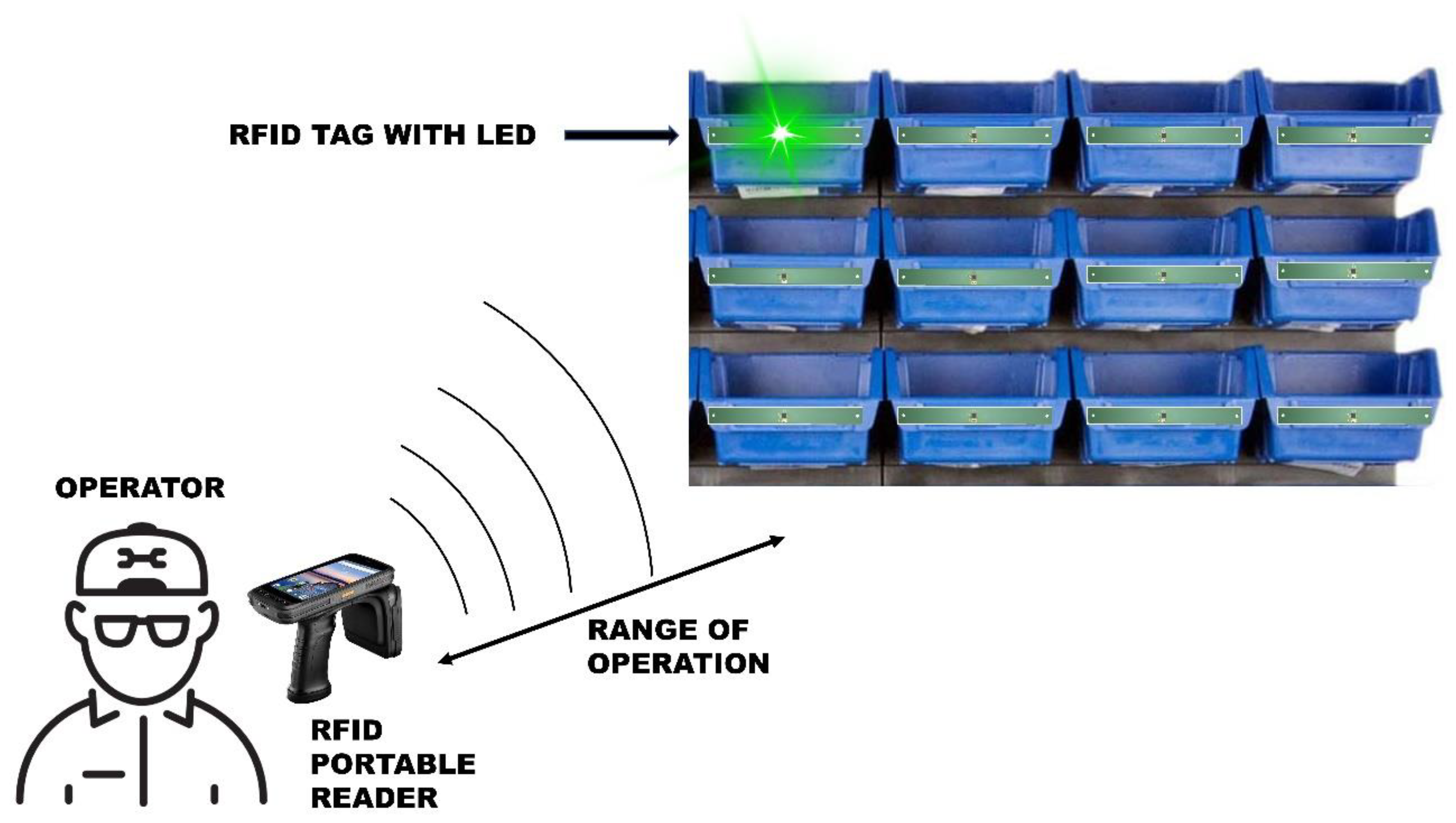
:1. Introduction
2. Solar-Powered Semi-Passive RFID Tag
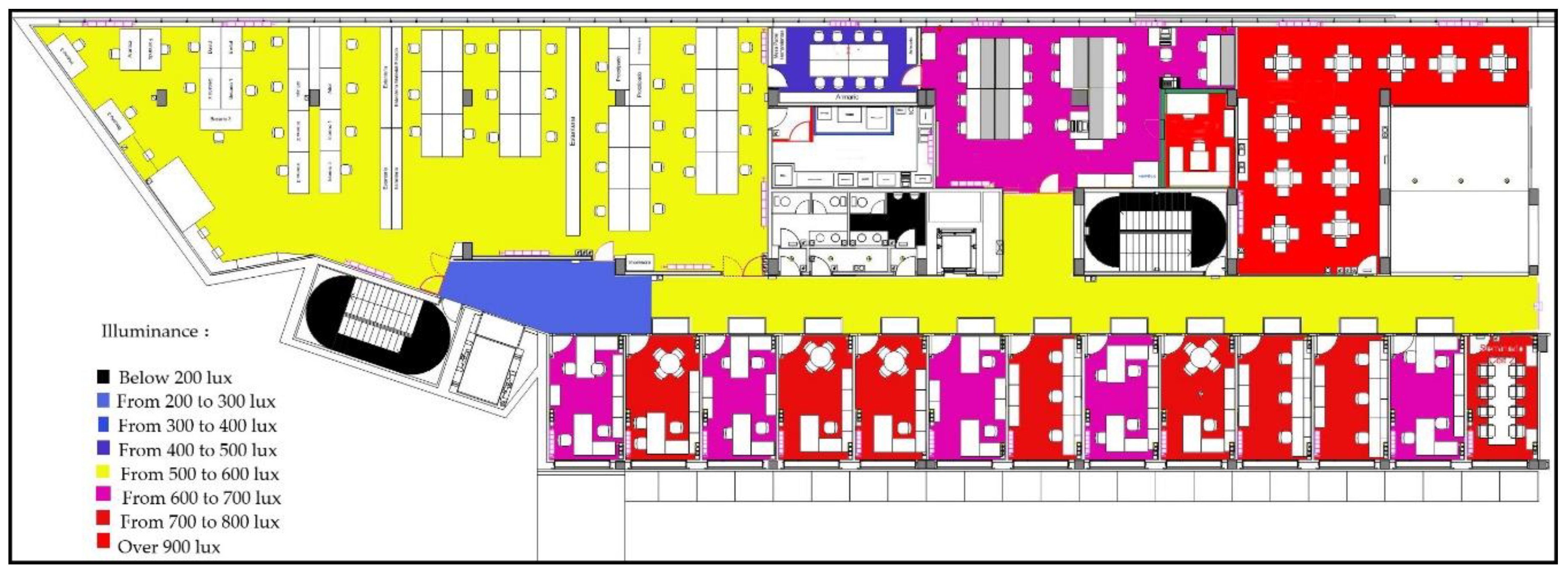
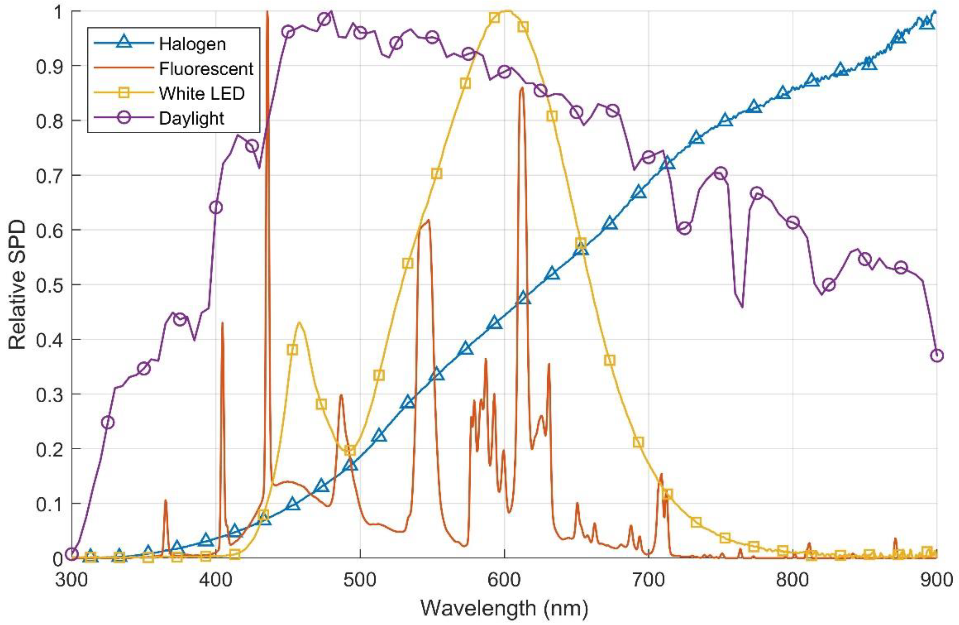
2.1. Lighting Conditions and Harvester Choices
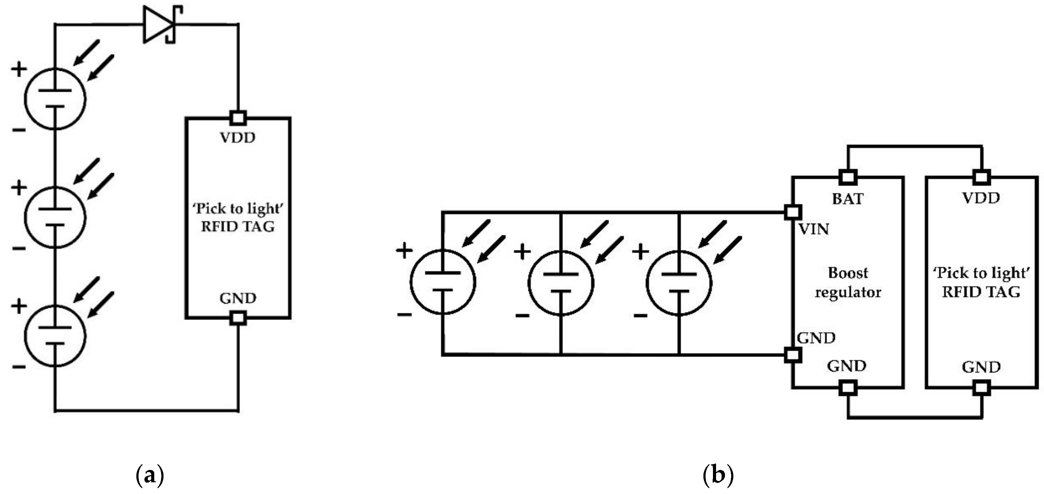
2.2. RFID Tag Architecture
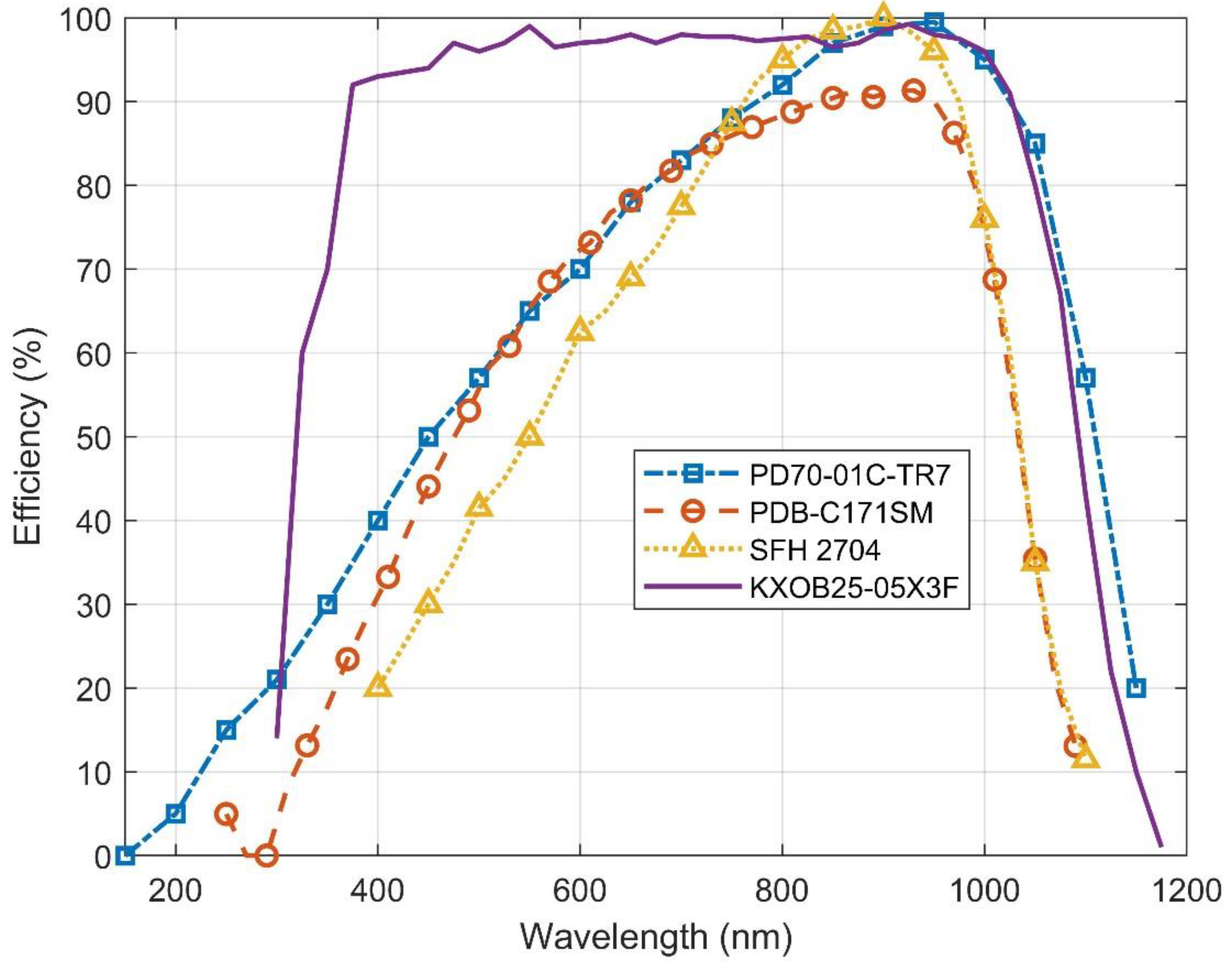
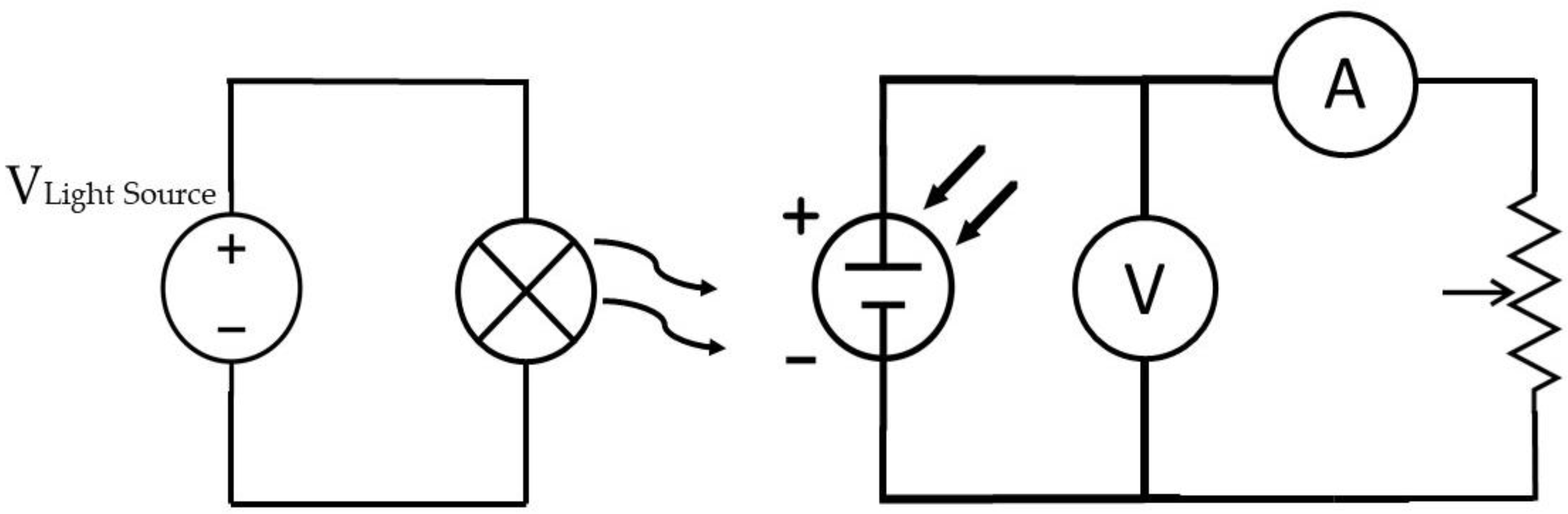
2.3. Solar Cell Implementation
3. Measurement Results
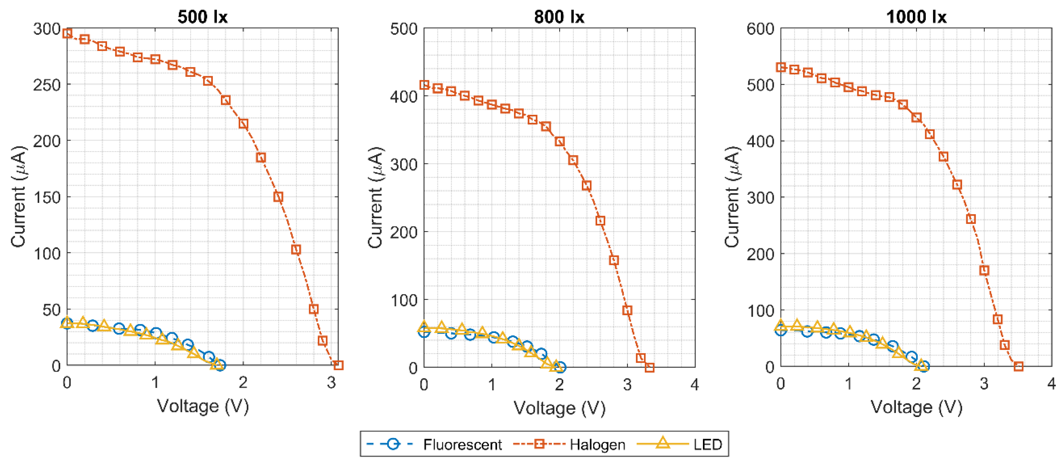
3.1. Solar Cell Arrangement
3.2. Photovoltaic Cell Powered Tag
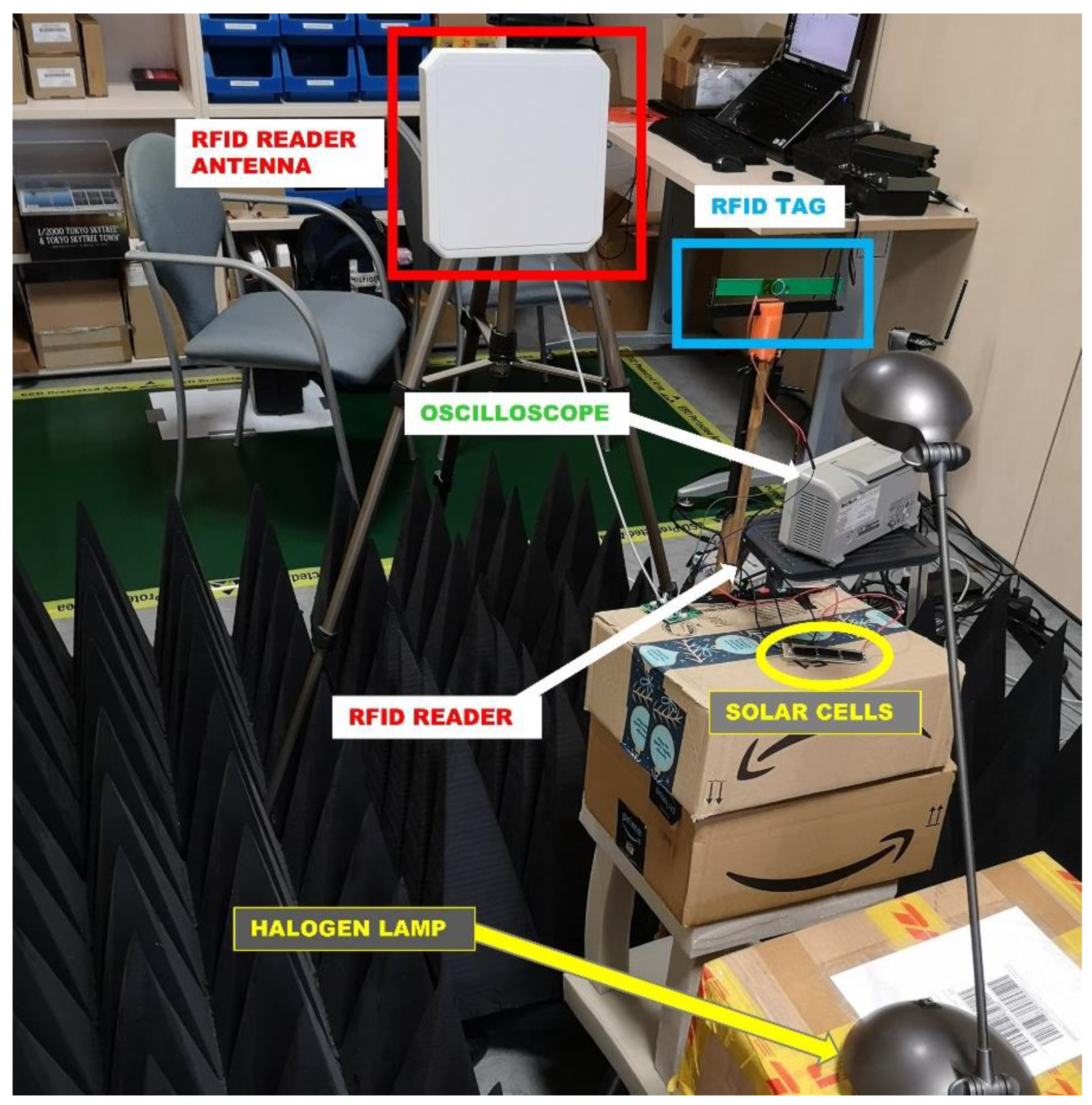
- A commercial reference tag was placed in the measurement set-up at a fixed distance of 70 cm between the reader and tag.
- The output power of the reader was gradually increased until a successful communication was reached.
- Considering the reader output power (PTX), its antenna gain (GTX), the reference RFID chip sensitivity (Psens), its antenna gain (GRX) and the wavelength, the theoretical communication range (d) was calculated using Friis equation [33]:
- 4.
- A correction factor was applied to the reader output power to compensate for the environmental effects and adjust the calculated distance to the real distance of 70 cm.
- 5.
- Steps 1 and 2 were repeated with the tag under test in the measurement set-up.
- 6.
- Using the reader output power obtained in step 5 and the correction factor of step 4, the tag sensitivity was obtained using Friis equation.
- 7.
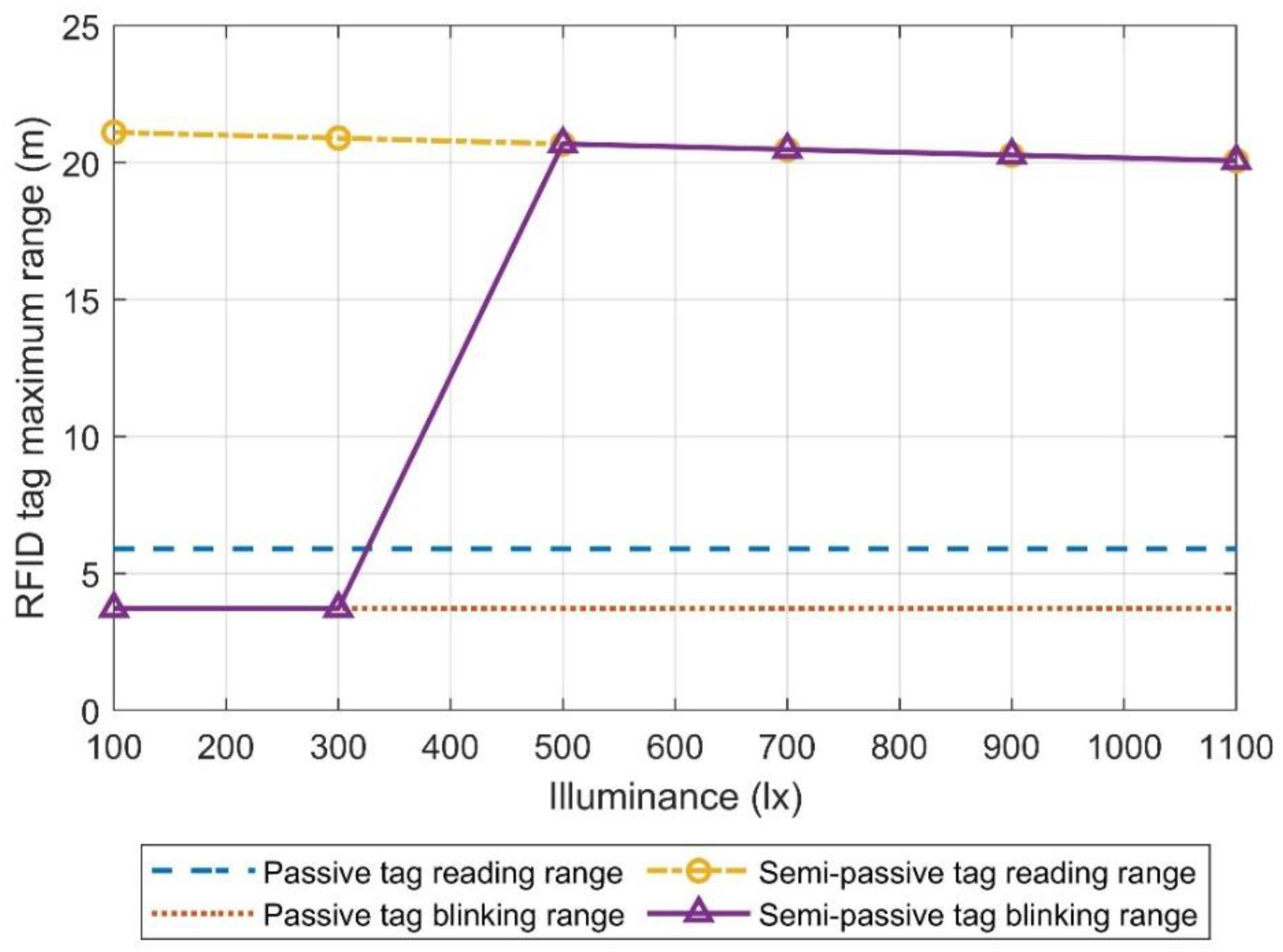
- Considering that according to the European regulation, the reader can transmit with up to 2 W EIRP and the tag sensitivity, the maximum communication range was calculated.
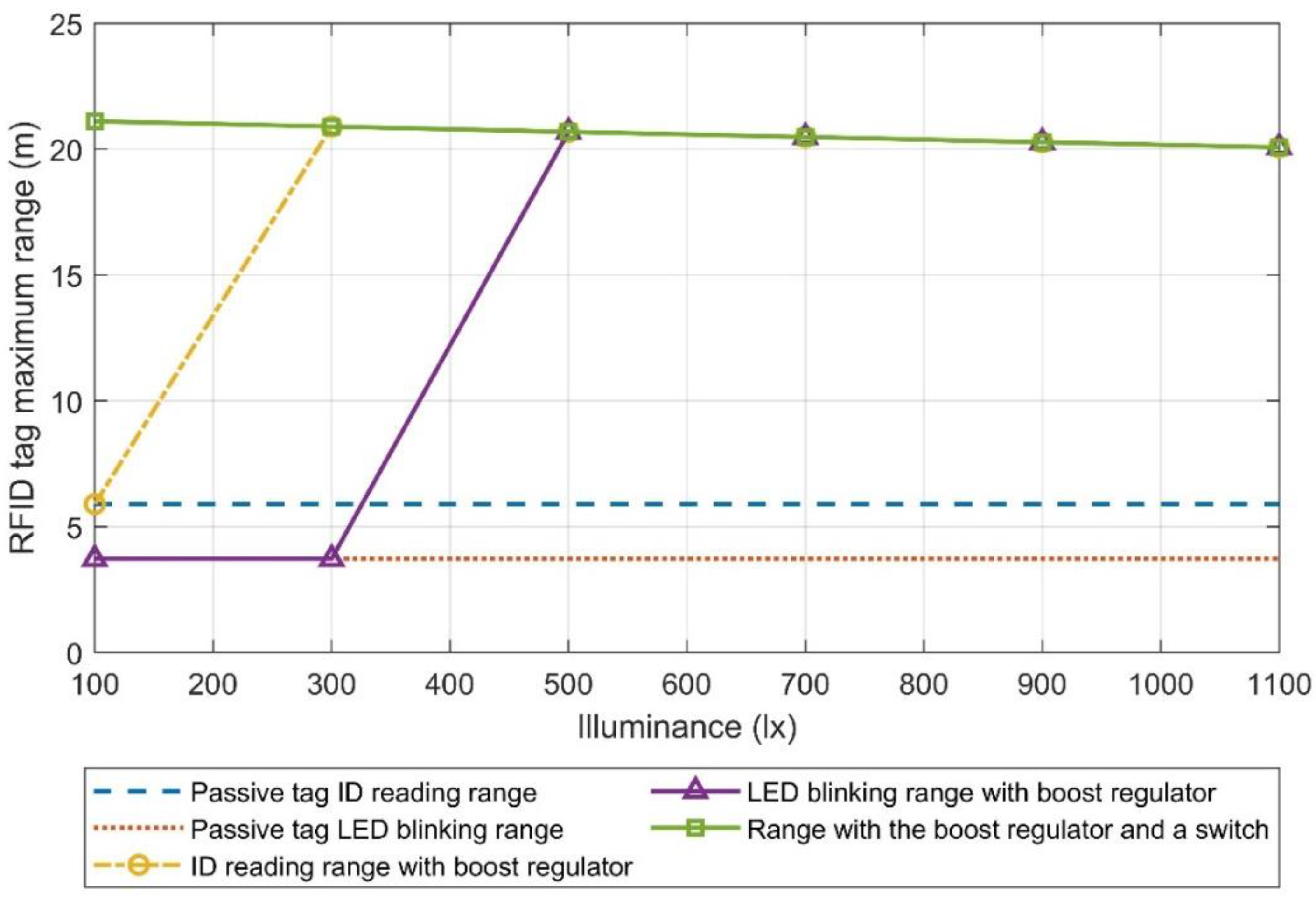
3.3. Solar Cells with Boost Regulator
4. Discussion
5. Patents
Author Contributions
Funding
Acknowledgments
Conflicts of Interest
References
- Al-Fuqaha, A.; Guizani, M.; Mohammadi, M.; Aledhari, M.; Ayyash, M. Internet of Things: A Survey on Enabling Technologies, Protocols, and Applications. IEEE Commun. Surv. Tutor. 2015, 17, 2347–2376. [Google Scholar] [CrossRef]
- Xu, L.D.; He, W.; Li, S. Internet of Things in Industries: A Survey. IEEE Trans. Ind. Inform. 2014, 10, 2233–2243. [Google Scholar] [CrossRef]
- Vaz, A.; Ubarretxena, A.; Zalbide, I.; Pardo, D.; Solar, H.; Garcia-Alonso, A.; Berenguer, R. Full Passive UHF Tag With a Temperature Sensor Suitable for Human Body Temperature Monitoring. IEEE Trans. Circuits Syst. 2010, 57, 95–99. [Google Scholar] [CrossRef]
- Duong, V.-H.; Hieu, N.X.; Lee, H.-S.; Lee, J.-W. A Battery-Assisted Passive EPC Gen-2 RFID Sensor Tag IC With Efficient Battery Power Management and RF Energy Harvesting. IEEE Trans. Ind. Electron. 2016, 63, 7112–7123. [Google Scholar] [CrossRef]
- Fabbri, D.; Berthet-Bondet, E.; Masotti, D.; Costanzo, A.; Dardari, D.; Romani, A. Long Range Battery-Less UHF-RFID Platform for Sensor Applications. In Proceedings of the 2019 IEEE International Conference on RFID Technology and Applications (RFID-TA), Pisa, Italy, 25–27 September 2019; pp. 80–85. [Google Scholar]
- Abdulhadi, A.E.; Denidni, T.A. Self-Powered Multi-Port UHF RFID Tag-Based-Sensor. IEEE J. Radio Freq. Identif. 2017, 1, 115–123. [Google Scholar] [CrossRef]
- Abdulhadi, A.E.; Abhari, R. Multiport UHF RFID-Tag Antenna for Enhanced Energy Harvesting of Self-Powered Wireless Sensors. IEEE Trans. Ind. Inform. 2016, 12, 801–808. [Google Scholar] [CrossRef]
- Virili, M.; Georgiadis, A.; Niotaki, K.; Collado, A.; Alimenti, F.; Mezzanotte, P.; Roselli, L.; Carvalho, N.B. Design and optimization of an antenna with Thermo-Electric Generator (TEG) for autonomous wireless nodes. In Proceedings of the 2014 IEEE RFID Technology and Applications Conference (RFID-TA), Tampere, Finland, 8–9 September 2014; pp. 21–25. [Google Scholar]
- Han, P.; Mei, N.; Zhang, Z. A UHF Semi-Passive RFID System with Photovoltaic/Thermoelectric Energy Harvesting for Wireless Sensor Networks. In Proceedings of the 2019 IEEE 13th International Conference on ASIC (ASICON), Chongqing, China, 29 October–1 November 2019; pp. 1–4. [Google Scholar]
- Abdelnour, A.; Hallet, A.; Dkhil, S.B.; Pierron, P.; Kaddour, D.; Tedjini, S. Energy Harvesting Based On Printed Organic Photovoltaic Cells for RFID Applications. In Proceedings of the 2019 IEEE International Conference on RFID Technology and Applications (RFID-TA), Pisa, Italy, 25–27 September 2019; pp. 110–112. [Google Scholar]
- Sample, A.P.; Braun, J.; Parks, A.; Smith, J.R. Photovoltaic enhanced UHF RFID tag antennas for dual purpose energy harvesting. In Proceedings of the 2011 IEEE International Conference on RFID, Orlando, FL, USA, 12–14 April 2011; pp. 146–153. [Google Scholar]
- Ascher, A.; Lehner, M.; Eberhardt, M.; Biebl, E. Improving the range of UHF RFID transponders using solar energy harvesting under low light conditions. Adv. Radio Sci. 2015, 13, 81–86. [Google Scholar] [CrossRef] [Green Version]
- Illuminance—Recommended Light Level. Available online: https://www.engineeringtoolbox.com/light-level-rooms-d_708.html (accessed on 1 September 2020).
- ISO-TECH ILM 1332A Digital Light Meter. Available online: https://datasheet.octopart.com/ILM1332-Iso-Tech-datasheet-32756669.pdf (accessed on 17 July 2020).
- Hernandez-Andres, J.; Romero, J.; Nieves, J.L.; Lee, R.L., Jr. Color and spectral analysis of daylight in southern Europe. J. Opt. Soc. Am. A Opt. Image Sci. Vis. 2001, 18, 1325–1335. [Google Scholar] [CrossRef]
- LSPDD: Lamp Spectral Power Distribution Database. Available online: http://galileo.graphycs.cegepsherbrooke.qc.ca/app/en/home (accessed on 28 August 2020).
- PD70-01C/TR7—Silicon Planar PIN Photodiode. Available online: https://www.everlight.com/file/ProductFile/PD70-01C-TR7.pdf (accessed on 6 September 2020).
- CHIPLED®, SFH 2704. Available online: https://www.osram.com/ecat/CHIPLED%C2%AE%20SFH%202704/com/en/class_pim_web_catalog_103489/global/prd_pim_device_6230418/ (accessed on 6 September 2020).
- PDB-C171SM—SMT Photodiode. Available online: https://media.digikey.com/pdf/Data%20Sheets/Photonic%20Detetectors%20Inc%20PDFs/PDB-C171SM.PDF (accessed on 6 September 2020).
- KXOB25-05X3F—IXOLARTM High Efficiency SolarBIT. Available online: https://ixapps.ixys.com/DataSheet/KXOB25_05X3F.pdf (accessed on 6 September 2020).
- PDB-C160SM—Photodiode in Plastic Surface Mount Package. Available online: https://media.digikey.com/pdf/Data%20Sheets/Photonic%20Detetectors%20Inc%20PDFs/PDB-C160SM_DS.pdf (accessed on 6 September 2020).
- SLSD-71N3—Solderable Planar Photodiode. Available online: http://www.farnell.com/datasheets/20429.pdf (accessed on 6 September 2020).
- Rocky100 IC Datasheet. Available online: http://www.farsens.com/wp-content/uploads/2017/12/DS-ROCKY100-V04.pdf (accessed on 7 November 2020).
- EVAL01-STELLA-R Datasheet. Available online: http://www.farsens.com/wp-content/uploads/2018/01/DS-EVAL01-STELLA-R-V03.pdf (accessed on 7 November 2020).
- ASMT-SWB5-NW703 Surface Mount LED Indicator. Available online: https://docs.broadcom.com/doc/ASMT-SWB5-Nxxxx-DS (accessed on 16 July 2020).
- Zoscher, L.; Grosinger, J.; Muehlmann, U.; Watzinger, H.; Bosch, W. RF voltage limiters for passive differential UHF RFID front-ends in a 40 nm CMOS technology. In Proceedings of the 2015 IEEE MTT-S International Microwave Symposium, Phoenix, AZ, USA, 17–22 May 2015; pp. 1–4. [Google Scholar]
- Beriain, A.; Rezola, A.; Rio, D.; Solar, H.; Gurutzeaga, I.; Berenguer, R. A High Accuracy 3.1V Voltage Limiter for Enabling High Performance RFID Sensor Applications. In Proceedings of the 2019 IEEE 62th International Midwest Symposium on Circuits and Systems (MWSCAS), Dallas, TX, USA, 4–7 August 2019; pp. 973–976. [Google Scholar]
- Beriain, A.; Zalbide, I.; Jimenez, A.; Galarraga, I.; Berenguer, R.; Alonso, A.; Navarro, E. Radio Frequency Identification (RFID) Tag and a Method for Limiting Supply Voltage of a RFID Tag. Patent EP 3236392 B1, 22 April 2016. [Google Scholar]
- RB751 Series Schottky Barrier Single Diodes. Available online: https://assets.nexperia.com/documents/data-sheet/RB751_SER.pdf (accessed on 24 September 2020).
- Ultralow Power Boost Regulator with MPPT and Charge Management. Available online: https://www.analog.com/media/en/technical-documentation/data-sheets/ADP5090.pdf (accessed on 28 July 2020).
- S8658WPR S8658WPL—Circular Polarity Wide Band RFID Panel Antenna. Available online: https://www.lairdconnect.com/documentation/ant-ds-s8658wpr-s8658wpl-0915pdf (accessed on 30 July 2020).
- SPEEDWAY R420 RAIN RFID READER. Available online: https://www.impinj.com/platform/connectivity/speedway-r420 (accessed on 16 July 2020).
- Kantareddy, S.N.R.; Mathews, I.; Bhattacharyya, R.; Peters, I.M.; Buonassisi, T.; Sarma, S.E. Long Range Battery-Less PV-Powered RFID Tag Sensors. IEEE Internet Things J. 2019, 6, 6989–6996. [Google Scholar] [CrossRef] [Green Version]
- Kantareddy, S.N.R.; Mathews, I.; Sun, S.; Layurova, M.; Thapa, J.; Correa-Baena, J.-P.; Bhattacharyya, R.; Buonassisi, T.; Sarma, S.E.; Peters, I.M. Perovskite PV-Powered RFID: Enabling Low-Cost Self-Powered IoT Sensors. IEEE Sens. J. 2020, 20, 471–478. [Google Scholar] [CrossRef] [Green Version]


| Device | Type | Package Area (mm2) | Active Area (mm2) | Peak Power 22 klx (μW) | Peak Power 500 lx (μW) | Power Per Package Area 22 klx (μW/mm2) | Power Per Package Area 500 lx (μW/mm2) |
|---|---|---|---|---|---|---|---|
| PDB-C160SM [21] | Photodiode | 16.85 | 8 | 40 | 0.9 | 2.37 | 0.05 |
| PD70-01C/TR7 [17] | Photodiode | 25 | 8 | 45 | 1.1 | 1.8 | 0.04 |
| SFH 2704 [18] | Photodiode | 3.6 | 1 | 15 | 0.3 | 4.17 | 0.08 |
| PDB-C171SM [19] | Photodiode | 21.2 | 8 | 63 | 1.35 | 2.97 | 0.06 |
| SLSD-71N300 [22] | Photodiode | 50.8 | 50 | 20 | 0.8 | 0.39 | 0.02 |
| KXOB25-05X3F [20] | Solar cell | 184 | 138 | >1126 | 11.57 | 6.12 | 0.06 |
| Illuminance (lx) | Input Current during Startup (μA) | Input Voltage during Startup (mV) | Solar Cell Open Circuit Voltage (V) | Maximum Output Voltage (V) | Time to Reach Maximum Output Voltage (s) |
|---|---|---|---|---|---|
| 100 | 160 | 376.6 | 0.683 | 0.735 | 42 |
| 300 | 656 | 380.5 | 0.893 | 1.722 | 120 |
| 500 | 810 | 383.3 | 0.97 | 3.153 | 20 |
| 700 | 1060 | 385.3 | 1.05 | 3.153 | 13 |
| 900 | 1450 | 389.5 | 1.13 | 3.153 | 8 |
| 1100 | 1780 | 391 | 1.18 | 3.153 | 6 |
| Illuminance (lx) | Maximum Output Voltage without Tag (V) | Time to Reach Maximum Output Voltage (s) | Output Voltage after Connecting the Tag (V) |
|---|---|---|---|
| 100 | 3.5 | 75 | 3.149 |
| 300 | 3.5 | 14 | 3.152 |
| 500 | 3.5 | 12 | 3.153 |
| 700 | 3.5 | 10 | 3.153 |
| 900 | 3.5 | 7 | 3.153 |
| 1100 | 3.5 | 4 | 3.153 |
| [33,34] | [10] | [7] | This Work | ||
|---|---|---|---|---|---|
| With Schottky Diode | With Boost Regulator | ||||
| IC read sensitivity | −8.3 dBm (passive) −31 dBm (BAP) | −7 dBm (passive) −15 dBm (BAP) | −17 dBm (passive) −24 dBm (BAP) | −14 dBm (passive) −24 dBm (BAP) −35 dBm (Enhanced BAP) | |
| PV harv. area | 2.8 cm2 | 54.02 cm2 | 5.52 cm2 | ||
| Maximum range | 4 m @ 925 MHz | 7.3 m @ 866 MHz | 27 m @ 932 MHz | 20.3 m @ 868 MHz | 21 m @ 868 MHz |
| Tag Sensitivity | −25.34 dBm @ 932 MHz | −23.34 dBm @ 868 MHz | −23.68 dBm @ 868 MHz | ||
| Lighting conditions | 1 sun (solar simulator) | 500–1000 lx | 500 lx (halogen) | 100 lx (halogen) | |
| Power load | 7.5 μW (read) 20 μW (20000 meas./h) | 9.6 μW (read) 270 μW (single temp. read) | 45 μW (read) | 8 μW (read) 31 μW (blink) | |
| Tag features | Temperature sensor | Temperature sensor | Temperature sensor, MCU and humidity sensor | LED indicator | |
| Component | Unit Price @ One Unit | Unit Price @ 1000 Units | Quantity (First Arrangement) | Quantity (Second Arrangement) |
|---|---|---|---|---|
| EVAL01-Stella-R-DKWB | 40 EUR | ----- | 1 | 1 |
| KXOB25-05X3F | 1.77 EUR | 1.20086 EUR | 3 | 3 |
| RB751V40,115 | 0.19 EUR | 0.03043 EUR | 1 | 0 |
| ADP5090 | 4.45 EUR | 2.69662 EUR | 0 | 1 |
Publisher’s Note: MDPI stays neutral with regard to jurisdictional claims in published maps and institutional affiliations. |
© 2020 by the authors. Licensee MDPI, Basel, Switzerland. This article is an open access article distributed under the terms and conditions of the Creative Commons Attribution (CC BY) license (http://creativecommons.org/licenses/by/4.0/).
Share and Cite
Astigarraga, A.; Lopez-Gasso, A.; Golpe, D.; Beriain, A.; Solar, H.; del Rio, D.; Berenguer, R. A 21 m Operation Range RFID Tag for “Pick to Light” Applications with a Photovoltaic Harvester. Micromachines 2020, 11, 1013. https://doi.org/10.3390/mi11111013
Astigarraga A, Lopez-Gasso A, Golpe D, Beriain A, Solar H, del Rio D, Berenguer R. A 21 m Operation Range RFID Tag for “Pick to Light” Applications with a Photovoltaic Harvester. Micromachines. 2020; 11(11):1013. https://doi.org/10.3390/mi11111013
Chicago/Turabian StyleAstigarraga, Aingeru, Alberto Lopez-Gasso, Diego Golpe, Andoni Beriain, Hector Solar, David del Rio, and Roc Berenguer. 2020. "A 21 m Operation Range RFID Tag for “Pick to Light” Applications with a Photovoltaic Harvester" Micromachines 11, no. 11: 1013. https://doi.org/10.3390/mi11111013