Article

A Theoretical Calculation Method of Ground Settlement Based on a Groundwater Seepage and Drainage Model in Tunnel Engineering

School of Civil Engineering, Lanzhou University of Technology, Lanzhou 730050, China
*
Author to whom correspondence should be addressed.
Sustainability 2021, 13(5), 2733; https://doi.org/10.3390/su13052733
Submission received: 20 January 2021 / Revised: 24 February 2021 / Accepted: 28 February 2021 / Published: 3 March 2021
(This article belongs to the Special Issue Advances in Geotechnical Engineering during Deep Energy Exploitation)

Abstract

:
Seepage is ubiquitous during tunneling in areas with high groundwater tables. The ground settlement trough on a single tunnel is well described by Peck’s formula, but it cannot reflect the settlement caused by seepage. In this paper, assuming that the groundwater inside and outside the tunnel is a one-dimensional steady-state seepage condition, the groundwater seepage and drainage model of the tunnel was established. Based on the model and the principle of groundwater dynamics, the seepage flow calculation formula was derived, and the dewatering funnel curve equation of the groundwater level surface of a tunnel aquifer was obtained. A case study of a tunnel project in Gansu Province was carried out, and the influence of seepage on the effective stress of the stratum around the tunnel and the calculation of ground settlement caused by seepage were analyzed. The results show that seepage makes the effective stress of the upper soil layer of the tunnel increase, which leads to an increase in ground deformation; when the groundwater level of the tunnel is greatly lowered, the seepage has a significant influence on the vertical deformation of the stratum.

1. Introduction

When a tunnel is excavated in areas with shallow groundwater levels, groundwater seepage will occur because of the effect of the water head difference inside and outside of the tunnel. The seepage of groundwater will change the pore water pressure and effective stress of the soil inside and outside of the tunnel, which not only affects the calculation of the surrounding rock pressure acting on the lining structure, but also affects the calculation of the vertical settlement deformation of the tunnel. Excessive deformation of the surrounding rock, ground subsidence cracking, and even collapse are the most common engineering issues caused by groundwater seepage during tunnel construction [1,2].
For undrained conditions, Peck (1969) proposed that the Gaussian function could reasonably describe the surface subsidence trough through the analysis of field observation data [3]. Later, Attewell and Farmer (1974) [4], O’Reilly and News (1982) [5], Sagaseta (1987) [6], Rankin (1988) [7], Mair et al. (1993) [8], Loganathan and Poulos (1998) [9], Lee et al. (1999) [10], and Marshall et al. (2012) [11] revised the calculation coefficient of the surface subsidence trough by considering factors such as tunnel depth and tunnel diameter, and popularized it. However, these methods were established without considering the influence of seepage and consolidation. In fact, the ground settlement caused by seepage and consolidation has not attracted enough attention. A limited number of studies on this topic, including Attewell et al. (1986) [12], O’Reilly et al. (1991) [13], Mair et al. (1991) [14], Bowers et al. (1996) [15], and Anagnostou (2002) [16], have studied the characteristics of surface settlement caused by tunnel excavation in aquifers. Except for the theoretical solutions mentioned above, extensive studies have also been performed on the subject using finite element numerical simulation [17,18,19,20], artificial intelligence [21,22,23,24], and model tests [25,26,27].
As discussed, previous research has mainly focussed on the calculation of land subsidence under the influence of non-seepage. In recent years, scholars have also studied the surrounding rock pressure and tunnel stability caused by groundwater seepage. Zareifard [2], based on the seepage stress and the principle of generalized effective stress, gives an analytical solution for the analysis and design of pressure tunnels. Cheng et al. [28] established the tunnel groundwater seepage model based on the area-well theory. The relation equation between the inflow of the tunnel and the drawdown of the groundwater level under the condition of unsteady seepage was derived. Weng et al. [29] carried out centrifugal model tests under different wetting conditions to explore the influence of wetting induced loess stratum collapse on a subway tunnel structure. In addition, the stability of the tunnel working face caused by seepage was also studied experimentally and numerically [30,31,32,33]. Recently, Chen et al. [34] developed a centrifugal model test device and carried out a series of centrifugal model tests in order to study the influence of steady-state seepage on the failure of a roadway working face. Lü et al. [35] carried out nine physical model tests, and obtained the displacement and earth pressure curves of a roadway working face. Pan and Dias [36] studied the working face stability of a circular tunnel in a weak rock mass under groundwater level based on the advanced 3D rotation collapse mechanism based on the background of the kinematic method of limit analysis. As reviewed above, a great deal of research has been done on the stability of a tunnel face caused by seepage, and the complex problem of ground subsidence caused by seepage in tunnel construction needs more practical verification.
In addition, the seepage pressure caused by groundwater seepage is very important to the tunnel lining. There are two types of divergement in tunnel drainage schemes—mainly drainage and mainly plugging. Although the former can reduce the permeability pressure of the lining, it cannot fix all types of water damage in the tunnel. However, when the latter tunnel completely blocks the underground water, it creates huge seepage pressure, especially buried deep into a long tunnel; the seepage pressure is even up to several megapascals. In fact, the drainage of the tunnel is similar to the pumping of a large-caliber well [37,38,39], and the dewatering funnel will be formed in the aquifer at the roof of the tunnel, which is essential to solve the subsidence problem caused by seepage. Therefore, groundwater seepage and tunnel engineering form a complex interaction chain. It is of practical significance to analyze the key links of this interaction chain in order to explore the mechanism of tunnel drainage seepage, to establish the calculation model of tunnel seepage settlement, and to reduce the environmental disasters caused by seepage.
In view of this, based on the steady-state seepage condition, the calculation formula of tunnel seepage was derived, and the dewatering funnel curve equation of the tunnel aquifer groundwater level was obtained. Furthermore, the influence of seepage on the effective stress of the stratum around the cavern, as well as the calculation of the ground settlement caused by it, were analyzed.

2. Seepage and Drainage Mechanism of a Tunnel Aquifer

Tunnel seepage will drain groundwater, which in turn changes the hydrogeological conditions of an aquifer. The groundwater level drops and forms a dewatering funnel and expands. It may also increase the permeability of the aquifer due to the dredging of the groundwater channel, resulting in the consolidation of the stratum within the scope of the dewatering funnel and formation settlement. Because seepage affects the tunnel design and stability calculation, it is very important to determine the drawdown value of the groundwater level and the scope of the dewatering funnel.

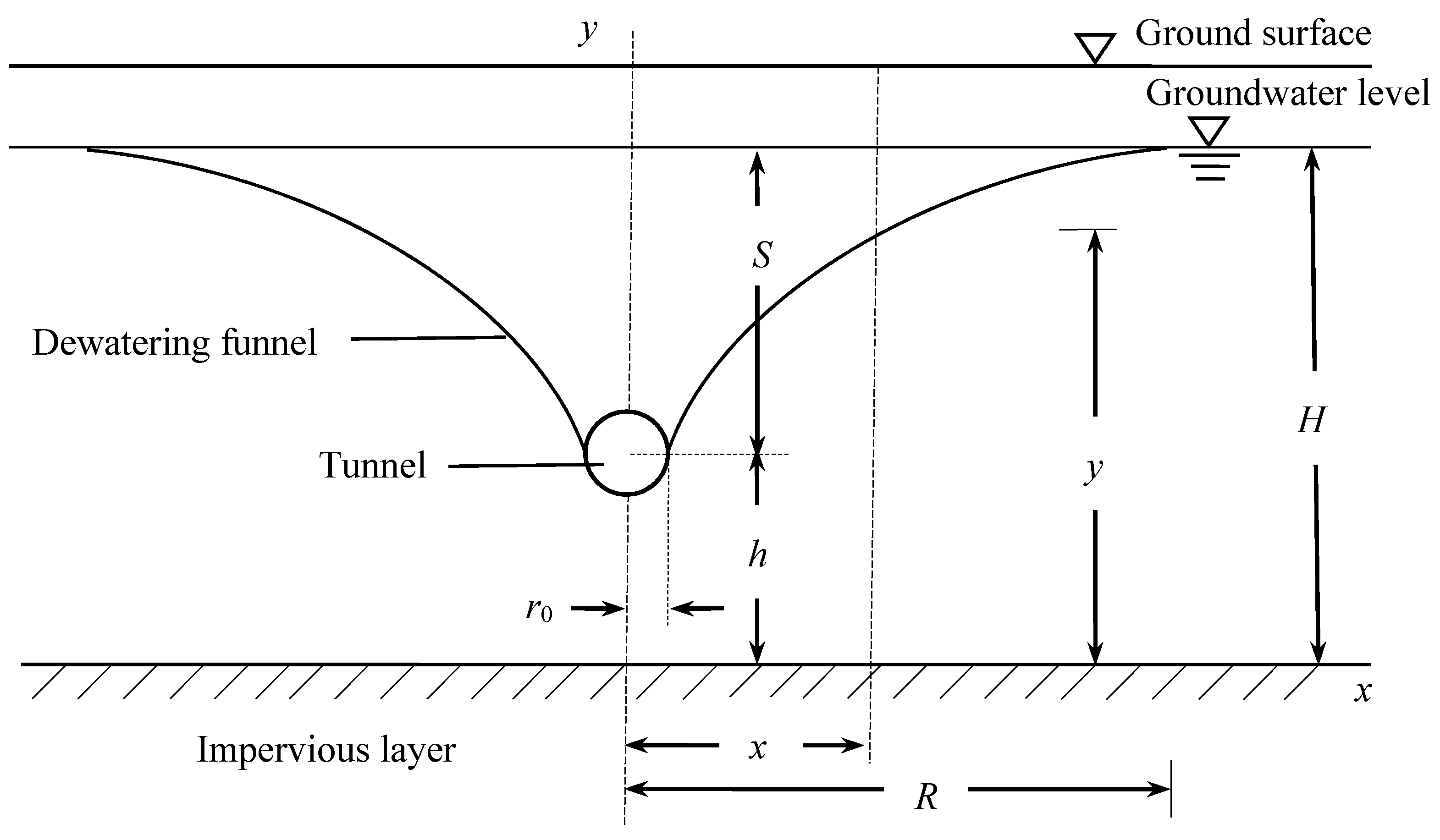
2.1. Tunnel Seepage Dewatering Funnel

In an area with a high groundwater level, the seepage effect is common when the tunnel is excavated. The formation seepage water loss is caused by the free surface formed by the excavation and unloading of the tunnel. At this stage, there is no lining after the tunnel is excavated, and the drainage is similar to the pumping of large-diameter wells. After a period of time, the seepage will tend to be stable. Generally, tunnels are in accordance with the unconformity condition of phreatic water [37]. Assuming that the tunnel is in a 1D steady-state seepage state, the phreatic surface changes from the original horizontal state to a funnel-shape, that is, a dewatering funnel is formed in the aquifer at the top of the tunnel, as shown in Figure 1. Assuming that the cross section of the tunnel is circular, the meaning of the symbols in Figure 1 are as follows: r0 is the tunnel radius, R is the radius of influence, Q is the seepage flow (also known as the water inflow), S is the drawdown of water level, H is the thickness of the phreatic aquifer, and h is the tunnel water level height (from diaphragm floor).

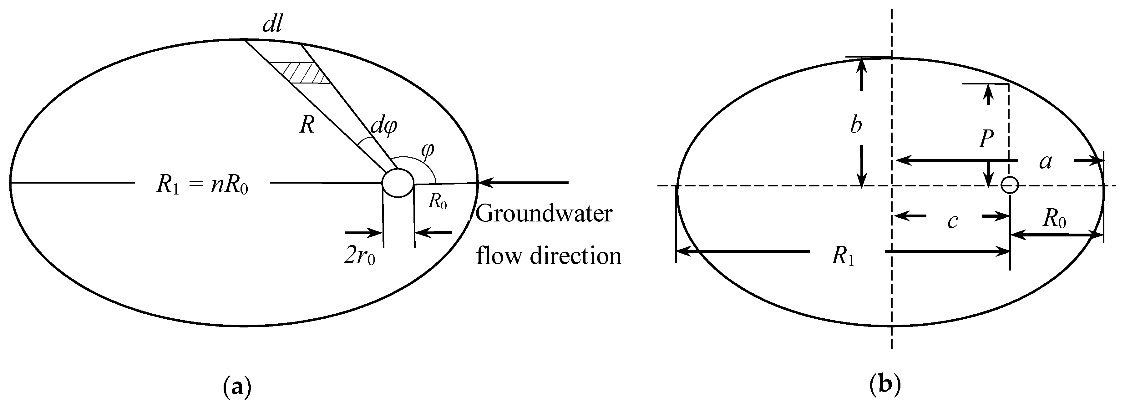
2.2. Seepage Equation of Phreatic Tunnel

Because the length of the tunnel is much larger than its section width, and the thickness of the water content in the portal section is small, the shape of the dewatering funnel at the top of the tunnel is different from that of the well point depression funnel. The spatial shape of the funnel is not an inverted cone but an inverted ellipsoid, and its ground range is not circular but approximately elliptical, as shown in Figure 2a.
According to the principle of polar coordinates, the seepage flow equation of the elliptical boundary dewatering funnel can be deduced. The derivation process is as follows:
Take the center of the tunnel as the origin of the polar coordinates.
R0 is the influence radius along the upstream of the groundwater flow and R1 is the influence radius of the groundwater flow downstream.
R 1 = n R 0
According to Darcy’s law, the phreatic water seepage differential equation can be obtained as follows:
d Q = k d ω I
In Equation (2), the micro cross section area of subsurface flow is the following:
d ω = d l y
The width of the micro cross section of the subsurface flow on the boundary of the funnel is as follows:
d l = R d φ
y is the depth of phreatic water, so the hydraulic gradient is as follows:
I = d y d R
By substituting the values of d ω and I into the differential equation of Equation (2), the following results can be obtained:
d Q = k R y d y d R d φ
By separating the variable and integral: h H y d y = d Q k d φ r 0 R d R R
We derive the following: H 2 h 2 2 = d Q k d φ ( ln R ln r 0 )
By shifting the items, the following results can be achieved:
d Q = k ( H 2 h 2 ) 2 d φ ln R r 0
The total flow of the tunnel can be obtained by integrating dQ. As the funnel is symmetrical to the subsurface flow direction surface, only one half of the funnel is integrated, i.e., from φ = 0 to φ = π . In order to obtain the total flow rate, the integral value should be doubled.
According to the above, the following is concluded:
Q = k ( H 2 h 2 ) 0 π d φ ln R r 0
When the pole is in the elliptic focus, as shown in Figure 2b, the polar elliptic equation is as follows:
R = P 1 + ε cos φ
where P is the focus parameter and ε is the eccentricity.
As R 1 = n R 0 , the values of a, b, c, P, and ε can be obtained according to Figure 2b.
The ellipse long half axis (a; along the direction of groundwater flow) is as follows:
a = R 1 + R 0 2 = R 0 n + 1 2
The distance between the focus and center of the ellipse is as follows:
c = a R 0 = R 0 n 1 2
The ellipse short half axis (b; perpendicular to the groundwater flow direction) is as follows:
b = a 2 c 2 = R 0 n
The focus parameter P is as follows:
p = b 2 a = R 0 2 n n + 1
The centrifugal rate is as follows:
ε = c a = n 1 n + 1
Substituting Equations (13) and (14) into Equation (9) yields
R = 2 n R 0 ( n + 1 ) ( 1 + n 1 n + 1 cos φ ) = 2 n ( n + 1 ) + ( n 1 ) cos φ R 0
Substituting Equation (15) into Equation (8) yields
Q = k ( H 2 h 2 ) 0 π d φ ln [ 2 n ( n + 1 ) + ( n 1 ) cos φ R 0 r 0 ]
According to this calculation, when R 0 / r 0 = 10 to 10,000 and n = 1 to 5, cos φ = 0 will not cause great error. As a result,
Q = k ( H 2 h 2 ) 1 ln ( 2 n n + 1 R 0 r 0 ) 0 π d φ = π k ( H 2 h 2 ) ln ( 2 n n + 1 R 0 r 0 )
where r0 is the tunnel radius (m), R is the radius of influence (m), Q is the seepage flow (also known as the water inflow); m3/d), H is the thickness of the phreatic aquifer (m), h = tunnel water level height (from diaphragm floor; m), and k is the permeability coefficient of the aquifer (m/d).

3. Dewatering Funnel Curve Equation

The boundary line of the cross section of the dewatering funnel is the groundwater level (phreatic line) after falling, as shown in Figure 1. Take the middle axis of the tunnel as the y axis (seepage thickness) with upward being positive, and take the x axis along the bottom plate of the water barrier with outward being positive. x is the horizontal distance between a certain point of the dewatering funnel curve and the tunnel axis, and y is the height of the infiltration curve at x from the tunnel axis (based on the impermeable layer surface). Generally, the tunnel conforms to the form of the phreatic incomplete well. According to the above Equation (17), if the upper and lower limit of the integral is changed to x from r0 to x, and y from h to y, respectively, and the dewatering funnel curve equation can be obtained as follows:
y 2 = h 2 + Q π k ln ( 2 n n + 1 x r 0 )
Substituting Equation (17) into Equation (18) yields
y 2 = h 2 + ( H 2 h 2 ) ( ln 2 n n + 1 + ln x r 0 R 0 r 0 )
Equation (19) is the dewatering funnel curve equation (or called the groundwater level distribution equation), which can quickly solve the water table height using arbitrary drawdown at any point from the tunnel axis. The equation shows that the dewatering funnel curve depends on the drawdown of h and H, and has nothing to do with Q and k.

4. Calculation of Ground Settlement Caused by Seepage

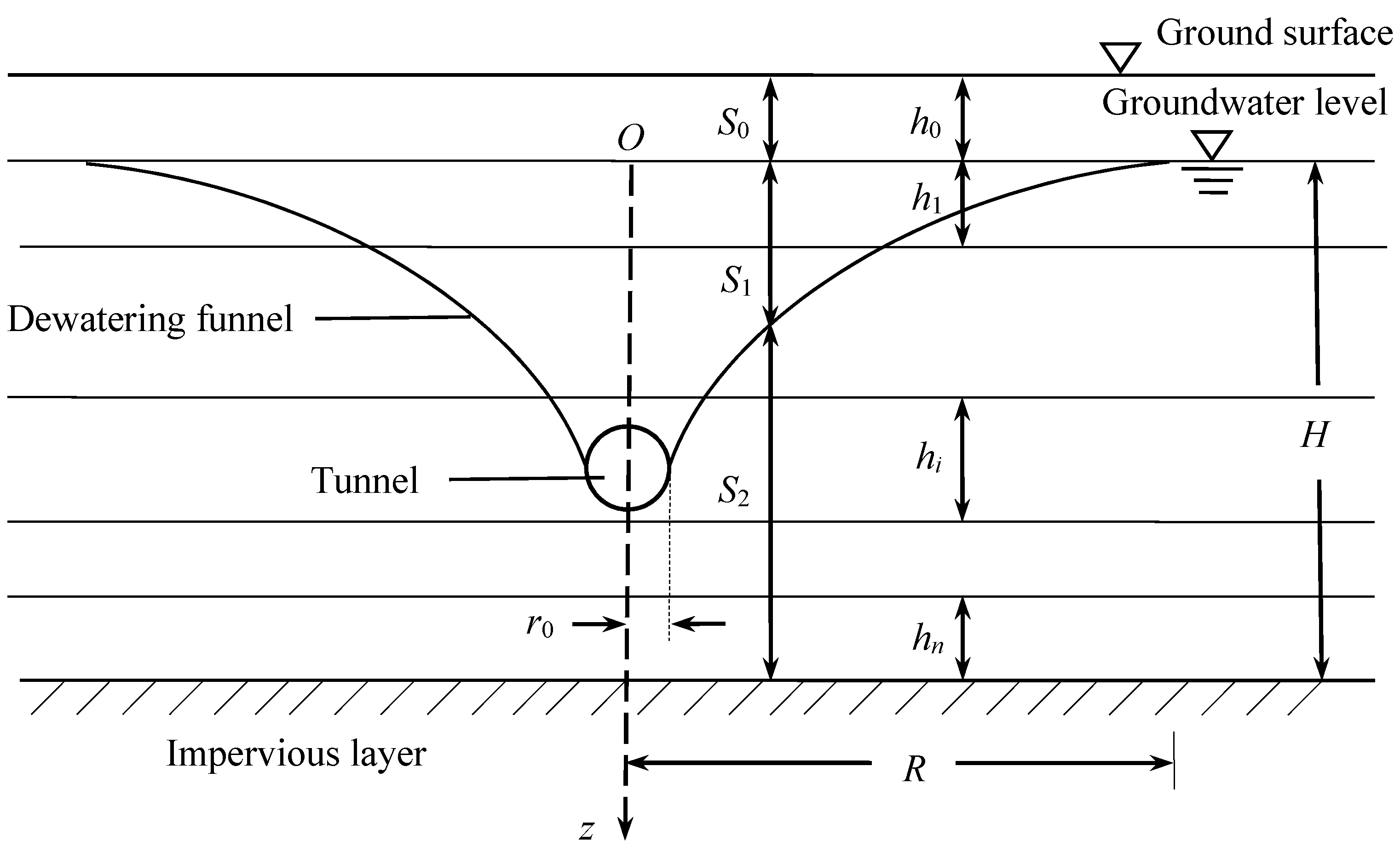
4.1. Problem Description

When excavating a tunnel in an area with a shallow groundwater level, seepage will occur because of the existence of the water head difference between the inside and outside of the tunnel. The seepage will cause the vertical effective stress of the soil layer at the top of the tunnel to increase, resulting in an increase in the deformation of the stratum at the top of the tunnel, which is manifested by the vertical settlement of the ground surface. The mechanism of ground settlement caused by seepage drainage can be explained by the Terzaghi effective stress principle:
σ = σ u w
where σ is the total stress of soil (kPa), σ’ is the effective stress of the soil skeleton (kPa), and uw is the pore water pressure (kPa).
In the process of tunnel seepage and water loss, assuming that the total stress of the soil layer is constant, the pore water pressure dissipates after water loss, which reduces the buoyancy force between soil particles, and the reduced pore water pressure is transformed into an effective stress increment, resulting in the compaction deformation of the soil skeleton, which is reflected as ground settlement at a macroscopic view.
Figure 3 is the schematic diagram of the tunnel seepage drainage. It is assumed that there are n layers of soil below the groundwater level of the stratum where the tunnel is located. Under the action of the water head difference inside and outside the tunnel, 1D steady-state seepage occurs along the vertical direction of z (z = 0 is the reference plane). The thicknesses of the soil layers below the groundwater level are h1, h2, …, hn. The permeability coefficients are k1, k2, …, kn. The compression modulus of each soil layer are E1, E2, …, En. The saturated unit weights are γsat1, γsat2, …, γsatn. The effective unit weights are γ’1, γ’2, …, γ’n. It is assumed that there is a layer of soil above the groundwater level at the top of the tunnel, and its thickness is h0.

4.2. Calculation Method of Ground Settlement Caused by Seepage
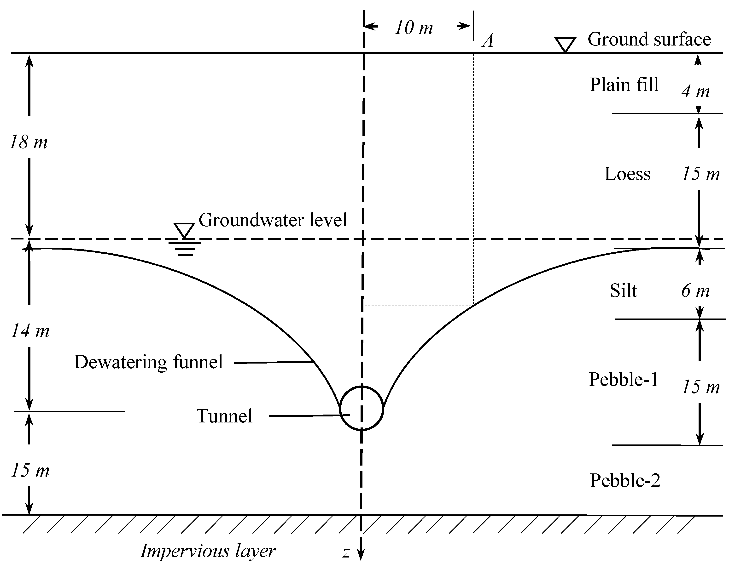
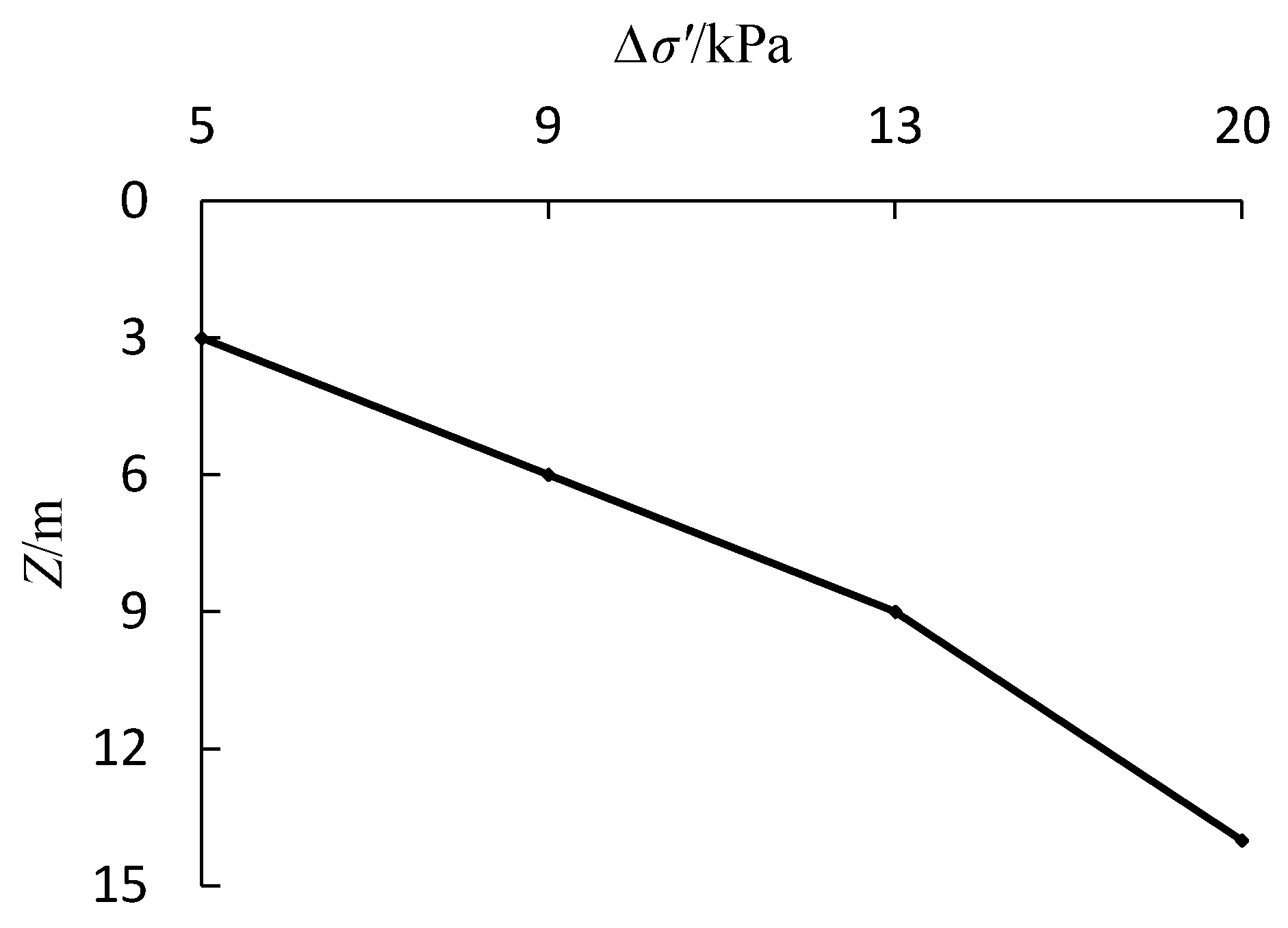
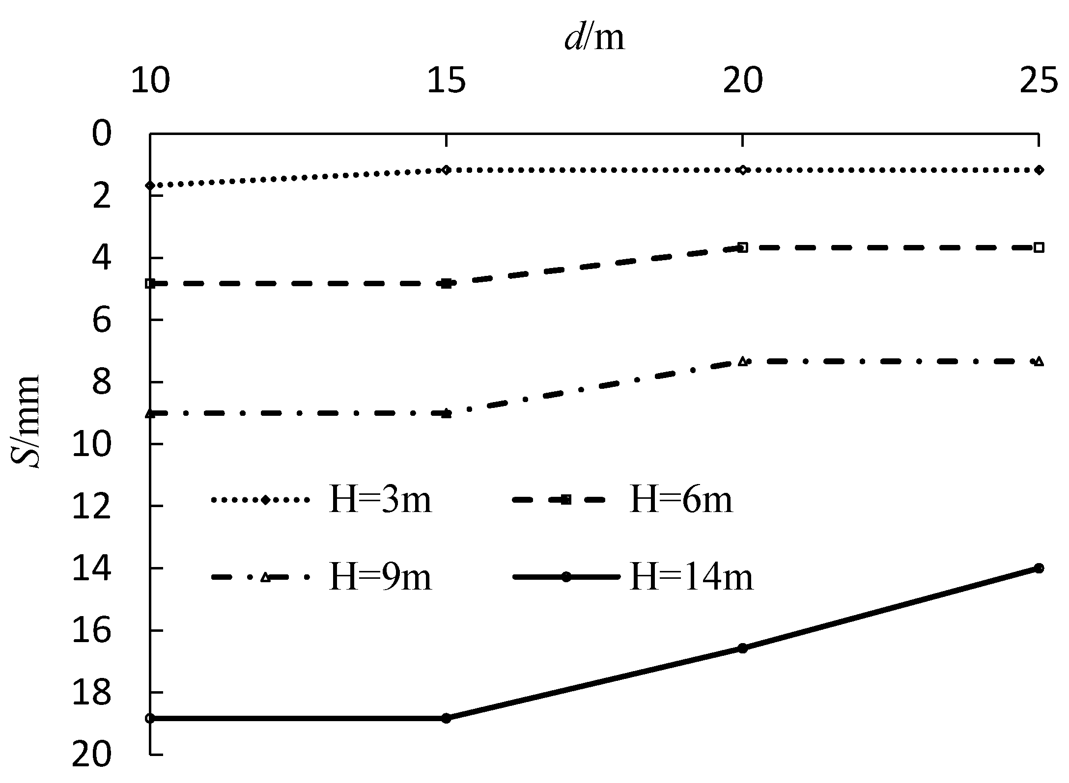
The vertical total stress and pore water pressure at any depth around the tunnel axis are as follows:
σ i ( z ) = j = 1 i 1 γ s a t ( j ) h j + γ s a t ( i ) ( z z i 1 )
u w ( i ) ( z ) = γ w z + γ w ( H y )
where z is the vertical distance between the calculated soil layer and the initial groundwater level (m). y is the surface height of stable dewatering funnel at the calculation point, y 2 = h 2 + ( H 2 h 2 ) ( ln 2 n n + 1 + ln x r 0 R 0 r 0 ) , m.
According to the effective stress principle of Terzaghi, it can be concluded that the vertical effective stress at any depth around the tunnel axis is as follows:
σ i ( z ) = σ i ( z ) u w ( i ) ( z ) = j = 1 i γ j h j + γ j ( z z i 1 ) γ w [ ( H y ) + z ]
Without considering the effect of seepage, the effective stress at any depth around the tunnel axis is as follows:
σ 0 ( i ) ( z ) = σ i ( z ) u w ( i ) ( z ) = j = 1 i γ j h j + γ j ( z z i 1 )
Thus, because of the effect of seepage, the effective stress increment at any depth around the tunnel axis is as follows:
Δ σ i ( z ) = σ i ( z ) σ 0 ( i ) ( z ) = γ w [ ( H y ) + z ]
The vertical effective stress of the soil mass on the top of the tunnel increases as a result of seepage, which makes the deformation of the stratum on the top of the tunnel increase. After the formation of the dewatering funnel, it is divided into the dry soil area (S0), the drainage area (S1), and the saturated area (S2), as shown in Figure 3. The soil mass in the S0 area is above the water level before and after precipitation, which can be regarded as the approximate dry soil area. There is no additional load caused by precipitation. If the compaction of soil is ignored, S0 = 0. In this paper, the settlement of three parts of soil was calculated separately. The effective stress increment of the soil in S1 area is Δ σ i ( z ) = i = 1 n γ w z , and that of saturated part in S2 area is Δ σ i ( z ) = i = 1 n γ w ( H y ) .
Thus, when considering the influence of seepage, the calculation formula of the increased ground settlement is as follows:
S = S 0 + S 1 + S 2 = S 1 + S 2 = i = 1 n γ w z E i h i + i = 1 n γ w ( H y ) E i h i
According to the above analysis, seepage makes the vertical effective stress on the top of the tunnel increase, which causes the vertical deformation of the stratum to increase. Therefore, it is dangerous to excavate the tunnel without considering the seepage effect in the area with a high groundwater level.

5. Case Study

We used a tunnel in Gansu Province as an example for our case study. According to the geological prospecting results, the groundwater that is exposed in the site is the pore diving of the Quaternary loose layer, and the main aquifer is the Quaternary sand and gravel layer, with a thickness of more than 200 m. The buried depth of the groundwater level is about 17.8-19.2 m, and the elevation is 1517.67–1517.78 m, which is about 13 m higher than that at the top of the tunnel. The depth of the tunnel precipitation is considered to be 14 m. The strata at a depth of 40 m are mainly Quaternary deposits, which are composed of Holocene plain fill, alluvial loess-like soil, silt, alluvial sandy pebble soil, and alluvial pebble soil of the lower Pleistocene. The physical and mechanical properties of the site strata from top to bottom are shown in Table 1. When the tunnel was excavated, the initial groundwater level was found to be about 18 m below the ground surface.
The tunnel radius r0 is 4 m. To simplify the calculation, n = 1 is taken in Equation (19), and the influence radius is R = 300 m. Figure 4 shows the schematic diagram of tunnel seepage. Taking point A at the surface, 10 m away from the tunnel axis, as an example, the vertical effective stress increment curve of each soil layer is shown in Figure 5. Obviously, because of the influence of seepage, the increment of vertical effective stress increases with the increase of the soil depth. This means that the effective stress of the upper soil layer in the tunnel considering the influence of seepage is larger than that without considering the influence of the seepage effect, so seepage makes the soil layer above the tunnel vertical change. According to Equation (26), the increased ground settlement at point A is 18.83 mm when seepage effect is considered.
Figure 6 shows the influence of different drawdowns on the surface subsidence. Assuming that the distance (L) between the tunnel location and the initial groundwater level is the drawdown, the ground settlement at any point from the tunnel axis can be calculated by Equation (26) using a different drawdown. The drawdowns are 3 m, 6 m, 9 m, and 14 m, and the distances from the tunnel axis are 10 m, 15 m, 20 m, and 25 m, respectively. The ground settlement caused by seepage is calculated. It can be seen from Figure 6 that when the drawdown of the water level is small, the loss of water head inside and outside the tunnel is less, and the increase of effective stress is less, so the influence of seepage on the vertical deformation of the stratum is small; when the drawdown is large, the loss inside and outside the water head tunnel is greater, and the effective stress increases even more, so the seepage has a greater impact on the vertical deformation of the stratum. The settlement law caused by seepage proposed by the research method in this paper is basically consistent with the law of settlement induced by tunnel dewatering in the literature [40], thus verifying the reliability of the method in this paper. In addition, the ground settlement caused by seepage is also affected by the water head difference inside and outside the tunnel and by the compression modulus of the soil.

6. Conclusions

When a tunnel is excavated in an area with a high groundwater table, there will be a water head difference inside and outside the tunnel, and seepage will occur.
Based on the theory of steady seepage, the model of groundwater seepage and drainage in the tunnel was established. The seepage calculation formula was derived, and the dewatering funnel curve equation of the tunnel aquifer groundwater level was obtained. According to the effective stress principle of Terzaghi, the influence of seepage on the effective stress of the surrounding strata and the calculation of the ground settlement caused by seepage are studied.
The method was tested in a case study. Through the seepage settlement calculation, the law of ground settlement caused by seepage was obtained. The results show that the seepage makes the effective stress of the upper soil layer of the tunnel increase, which leads to an increase in the deformation of the stratum. Therefore, when the groundwater level of the tunnel is greatly reduced, the vertical deformation of the upper soil layer of the tunnel is greater.
It is an important measure to limit the ground settlement to reduce the seepage flow as far as possible when excavating a tunnel in a high water content stratum. However, the tunnel engineering seepage has a strong 3D characteristics, and there is a coordinated deformation of the lining structure and soil in the actual engineering. For these more complex cases, further research work is needed.

Author Contributions

Conceptualization, Z.W.; methodology, Z.W.; validation, Z.W. and Y.Z.; formal analysis, Z.W.; investigation, Z.W.; writing—original draft preparation, Z.W.; writing—review and editing, Z.W. and Y.Z.; supervision, Y.Z. All authors have read and agreed to the published version of the manuscript.

Funding

The work presented in this manuscript was supported by the Ministry of Education Chang Jiang Scholars Innovation Team (grant number IRT_17R51).

Institutional Review Board Statement

Not applicable.

Informed Consent Statement

Not applicable.

Data Availability Statement

Data is available on request from the corresponding author of the manuscript.

Acknowledgments

The authors gratefully acknowledge the financial support of the Ministry of Education Chang jiang Scholars Innovation Team (grant number IRT_17R51). The authors are also grateful to the reviewers for their helpful advice and comments.

Conflicts of Interest

The authors declare no conflict of interest.

References

  1. Li, K.; Guo, Z.; Wang, L.; Jiang, H. Effect of seepage flow on shields number around a fixed and sagging pipeline. Ocean Eng. 2019, 172, 487–500. [Google Scholar] [CrossRef]
  2. Zareifard, M. An analytical solution for design of pressure tunnels considering seepage loads. Appl. Math. Model. 2018, 62, 62–85. [Google Scholar] [CrossRef]
  3. Peck, R. Deep Excavation and Tunneling in Soft Ground. In Proceedings of the 7th International Conference Soil Mechanics and Foundation Engineering, Mexico City, Mexico, 21 August 1969; State of the Art Volume. Sociedad Mexicana de Mecánica: Mexico City, Mexico, 1969; pp. 225–290. [Google Scholar]
  4. Attewell, P.B.; Farmer, I.W. Ground deformations resulting from shield tunnelling in London Clay. Can. Geotech. J. 1974, 11, 380–395. [Google Scholar] [CrossRef]
  5. O’Reilly, M.P.; News, B.M. Settlements above tunnels in the United Kingdom their magnitude and prediction. In Proceedings of the Tunnelling’82 Symposium, Brighton, UK, 7–11 June 1982; Institution of Mining and Metallurgy: London, UK, 1982. [Google Scholar]
  6. Sagaseta, C. Analysis of undrained soil deformation due to ground loss. Géotechnique 1987, 37, 301–320. [Google Scholar] [CrossRef]
  7. Rankin, W.J. Ground movement resulting from urban tunnelling: Predictions and effects. In Proceedings of the 23rd Annual Conference on the Engineering Group of the Geological Society, London, UK, 1 January 1988; Nottingham University: Nottingham, UK, 1988. [Google Scholar]
  8. Mair, R.J.; Taylor, R.N.; Bracegirdle, A. Subsurface settlement profiles above tunnels in clays. Géotechnique 1993, 43, 315–320. [Google Scholar] [CrossRef]
  9. Loganathan, N.; Poulos, H.G. Analytical prediction for tunneling induced ground movement in clays. ASCE J. Geotech. Geoenviron. Eng. 1998, 124, 846–856. [Google Scholar] [CrossRef]
  10. Lee, C.J.; Wu, B.R.; Chiou, S.Y. Soil movements around a tunnel in soft soils. Proc. Natl. Sci. Counc. Part A Phys. Sci. Eng. 1999, 23, 235–247. [Google Scholar]
  11. Marshall, A.M.; Farrell, R.; Klar, A.; Mair, R.J. Tunnels in sands: The effect of size, depth and volume loss on greenfield displacements. Géotechnique 2012, 62, 385–399. [Google Scholar] [CrossRef]
  12. Attewell, P.B.; Yeates, J.; Selby, A.R. Ground deformation and strain equations. In Soil Movements Induced by Tunneling and Their Effects on Pipeline and Structures; Glasgow: Blackie, AB, Canada, 1986; pp. 53–66. [Google Scholar]
  13. O’Reilly, M.P.; Mair, R.J.; Alderman, G.H. Long-term settlements over Tunnels. An eleven-year study at grimsby. In Tunnelling’91 London; Institution of Mining and Metallurgy: London, UK, 1991; pp. 55–64. [Google Scholar]
  14. Mair, R.J.; Potts, D.M.; Hight, D.W. Finite element analyses of settlements around a tunnel in soft ground. In Contractor Report; Transport and Road Research Laboratory: Berkshire, UK, 1991. [Google Scholar]
  15. Bowers, K.H.; Hiller, D.M.; New, B.M. Ground movement over three years at the Heathrow Express Trial Tunnel. In Geotechnical Aspects of Underground Construction in Soft Ground; Taylor, M., Ed.; Routledge: London, UK, 1996; pp. 647–652. [Google Scholar]
  16. Anagnostou, G. Urban tunnelling in water bearing ground—Common problems and soil mechanical analysis methods. In Proceedings of the Planning and Engineering for the Cities of Tomorrow, Second International Conference on Soil Structure Interaction in Urban Civil Engineering, Zurich, Switzerland, 7–8 March 2002; pp. 233–240. [Google Scholar]
  17. Jallow, A.; Ou, C.; Lim, A. Three-dimensional numerical study of long-term settlement induced in shield tunneling. Tunn. Undergr. Space Technol. 2019, 88, 221–236. [Google Scholar] [CrossRef]
  18. Kwong, A.K.L.; Ng, C.C.W.; Schwob, A. Control of settlement and volume loss induced by tunneling under recently reclaimed land. Undergr. Space 2019, 4, 289–301. [Google Scholar] [CrossRef]
  19. Miliziano, S.; De Lillis, A. Predicted and observed settlements induced by the mechanized tunnel excavation of metro line C near S. Giovanni station in Rome. Tunn. Undergr. Space Technol. 2019, 86, 236–246. [Google Scholar] [CrossRef]
  20. Klotoé, C.H.; Bourgeois, E. Three dimensional finite element analysis of the influence of the umbrella arch on the settlements induced by shallow tunneling. Comput. Geotech. 2019, 110, 114–121. [Google Scholar] [CrossRef]
  21. Moghaddasi, M.; Noorian-Bidgoli, M. ICA-ANN, ANN and multiple regression models for prediction of surface settlement caused by tunneling. Tunn. Undergr. Space Technol. 2018, 79, 197–209. [Google Scholar] [CrossRef]
  22. Ahangari, K.; Moeinossadat, S.R.; Behnia, D. Estimation of tunnelling-induced settlement by modern intelligent methods. Soils Found. 2015, 55, 737–748. [Google Scholar] [CrossRef] [Green Version]
  23. Suwansawat, S.; Einstein, H.H. Artificial neural networks for predicting the maximum surface settlement caused by EPB shield tunneling. Tunn. Undergr. Space Technol. 2006, 21, 133–150. [Google Scholar] [CrossRef]
  24. Pourtaghi, A.; Lotfollahi-Yaghin, M.A. Wavenet ability assessment in comparison to ANN for predicting the maximum surface settlement caused by tunneling. Tunn. Undergr. Space Technol. 2012, 28, 257–271. [Google Scholar] [CrossRef]
  25. Ni, P.; Mangalathu, S. Fragility analysis of gray iron pipelines subjected to tunneling induced ground settlement. Tunn. Undergr. Space Technol. 2018, 76, 133–144. [Google Scholar] [CrossRef]
  26. Lee, K.M.; Ji, H.W.; Shen, C.K.; Liu, J.H.; Bai, T.H. Ground response to the construction of Shanghai metro tunnel-line 2. Soils Found. 1999, 39, 113–134. [Google Scholar] [CrossRef] [Green Version]
  27. Zheng, G.; Tong, J.; Zhang, T.; Wang, R.; Fan, Q.; Sun, J.; Diao, Y. Experimental study on surface settlements induced by sequential excavation of two parallel tunnels in drained granular soil. Tunn. Undergr. Space Technol. 2020, 98, 103347. [Google Scholar] [CrossRef]
  28. Cheng, P.; Zhao, L.; Luo, Z.; Li, L.; Li, Q.; Deng, X.; Peng, W. Analytical solution for the limiting drainage of a mountain tunnel based on area-well theory. Tunn. Undergr. Space Technol. 2019, 84, 22–30. [Google Scholar] [CrossRef]
  29. Weng, X.; Sun, Y.; Zhang, Y.; Niu, H.; Liu, X.; Dong, Y. Physical modeling of wetting-induced collapse of shield tunneling in loess strata. Tunn. Undergr. Space Technol. 2019, 90, 208–219. [Google Scholar] [CrossRef]
  30. Yang, F.; Zhang, C.; Zhou, H.; Liu, N.; Zhang, Y.; Azhar, M.U.; Dai, F. The long-term safety of a deeply buried soft rock tunnel lining under inside-to-outside seepage conditions. Tunn. Undergr. Space Technol. 2017, 67, 132–146. [Google Scholar] [CrossRef]
  31. Perazzelli, P.; Leone, T.; Anagnostou, G. Tunnel face stability under seepage flow conditions. Tunn. Undergr. Space Technol. 2014, 43, 459–469. [Google Scholar] [CrossRef]
  32. Perazzelli, P.; Cimbali, G.; Anagnostou, G. Stability under seepage flow conditions of a tunnel face reinforced by bolts. Procedia Eng. 2017, 191, 215–224. [Google Scholar] [CrossRef]
  33. Sahoo, J.P.; Kumar, B. Support pressure for stability of circular tunnels driven in granular soil under water table. Comput. Geotech. 2019, 109, 58–68. [Google Scholar] [CrossRef]
  34. Chen, R.; Yin, X.; Tang, L.; Chen, Y. Centrifugal model tests on face failure of earth pressure balance shield induced by steady state seepage in saturated sandy silt ground. Tunn. Undergr. Space Technol. 2018, 81, 315–325. [Google Scholar] [CrossRef]
  35. Lü, X.; Zhou, Y.; Huang, M.; Zeng, S. Experimental study of the face stability of shield tunnel in sands under seepage condition. Tunn. Undergr. Space Technol. 2018, 74, 195–205. [Google Scholar] [CrossRef]
  36. Pan, Q.; Dias, D. Three dimensional face stability of a tunnel in weak rock masses subjected to seepage forces. Tunn. Undergr. Space Technol. 2018, 71, 555–566. [Google Scholar] [CrossRef]
  37. Jiang, Z. Interaction between tunnel engineering and water environment. Chin. J. Rock Mech. Eng. 2005, 24, 121–127. (In Chinese) [Google Scholar]
  38. Yoo, C. Ground settlement during tunneling in groundwater drawdown environment-Influencing factors. Undergr. Space 2018, 1, 20–29. [Google Scholar] [CrossRef] [Green Version]
  39. Zhang, P.; Chen, R.P.; Wu, H.N.; Liu, Y. Ground settlement induced by tunneling crossing interface of water-bearing mixed ground: A lesson from Changsha, China. Tunn. Undergr. Space Technol. 2020, 96, 103224. [Google Scholar] [CrossRef]
  40. Yoo, C.; Lee, Y.; Kim, S.H.; Kim, H.T. Tunnelling-induced ground settlements in a groundwater drawdown environment—A case history. Tunn. Undergr. Space Technol. 2012, 29, 69–77. [Google Scholar] [CrossRef]
Figure 1. Profile of the dewatering funnel of a tunnel.
Sustainability 13 02733 g001
Figure 2. Oval drain funnel and calculation parameters: (a) schematic diagram of oval drain funnel; (b) schematic diagram for calculating parameters of oval drain funnel.
Sustainability 13 02733 g002
Figure 3. Schematic diagram of the tunnel seepage and drainage.
Sustainability 13 02733 g003
Figure 4. Schematic diagram of the tunnel seepage.
Sustainability 13 02733 g004
Figure 5. Effective stress increment curve of each soil layer.
Sustainability 13 02733 g005
Figure 6. Influence of different drawdown on the surface subsidence.
Sustainability 13 02733 g006
Table 1. Physical parameters of the soils.
Soil Typeshi/mki/m·d−1Ei/MPaγd/kN·m−3
Plain fill4813.1
Loess1551013.5
Silt653014.7
Pebble-115604021.4
Pebble-2>200606022.7
Publisher’s Note: MDPI stays neutral with regard to jurisdictional claims in published maps and institutional affiliations.

