Hybrid Fly Ash-Based Geopolymeric Foams: Microstructural, Thermal and Mechanical Properties

 , ,
, ,  ,
,  and
and
Abstract
:1. Introduction
2. Experimental Section
2.1. Materials and Methods
2.2. Specimen Preparation
2.2.1. Solid Geopolymers
2.2.2. Geopolymer–Polysiloxane Hybrids
2.2.3. Curing Treatments
2.3. Physical and Microstructural Assessment
2.4. Apparent Density Determination
2.5. Compressive Behavior
2.6. Thermal Characterization
3. Results and Discussion
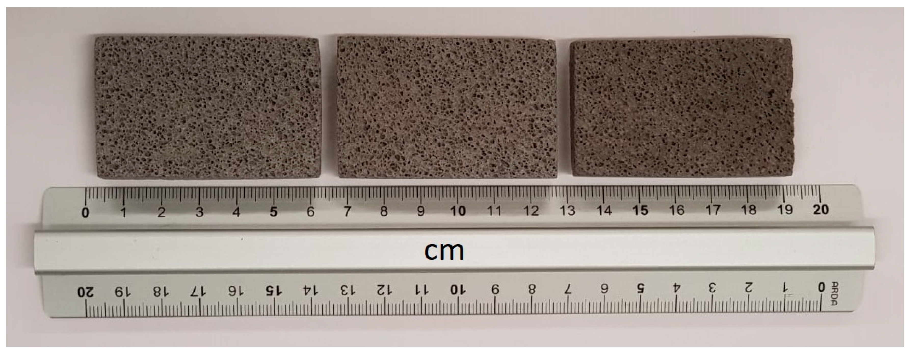
3.1. Sample Preparation
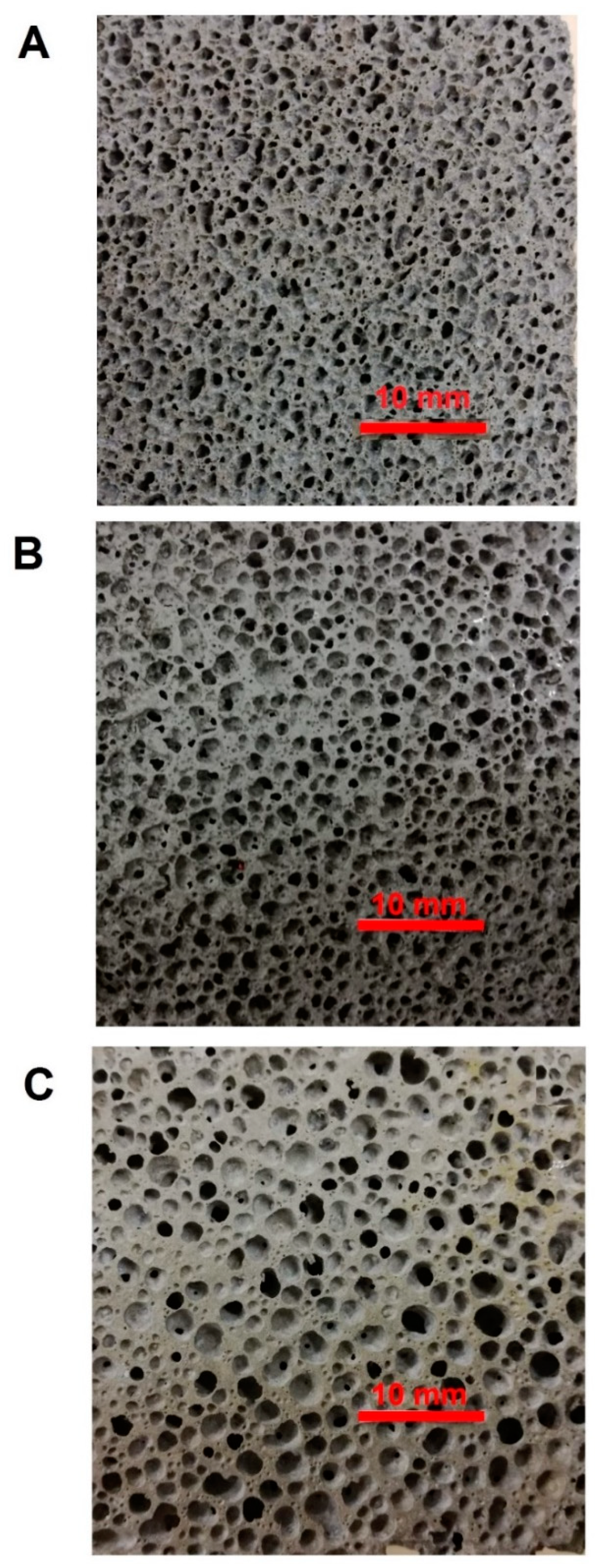
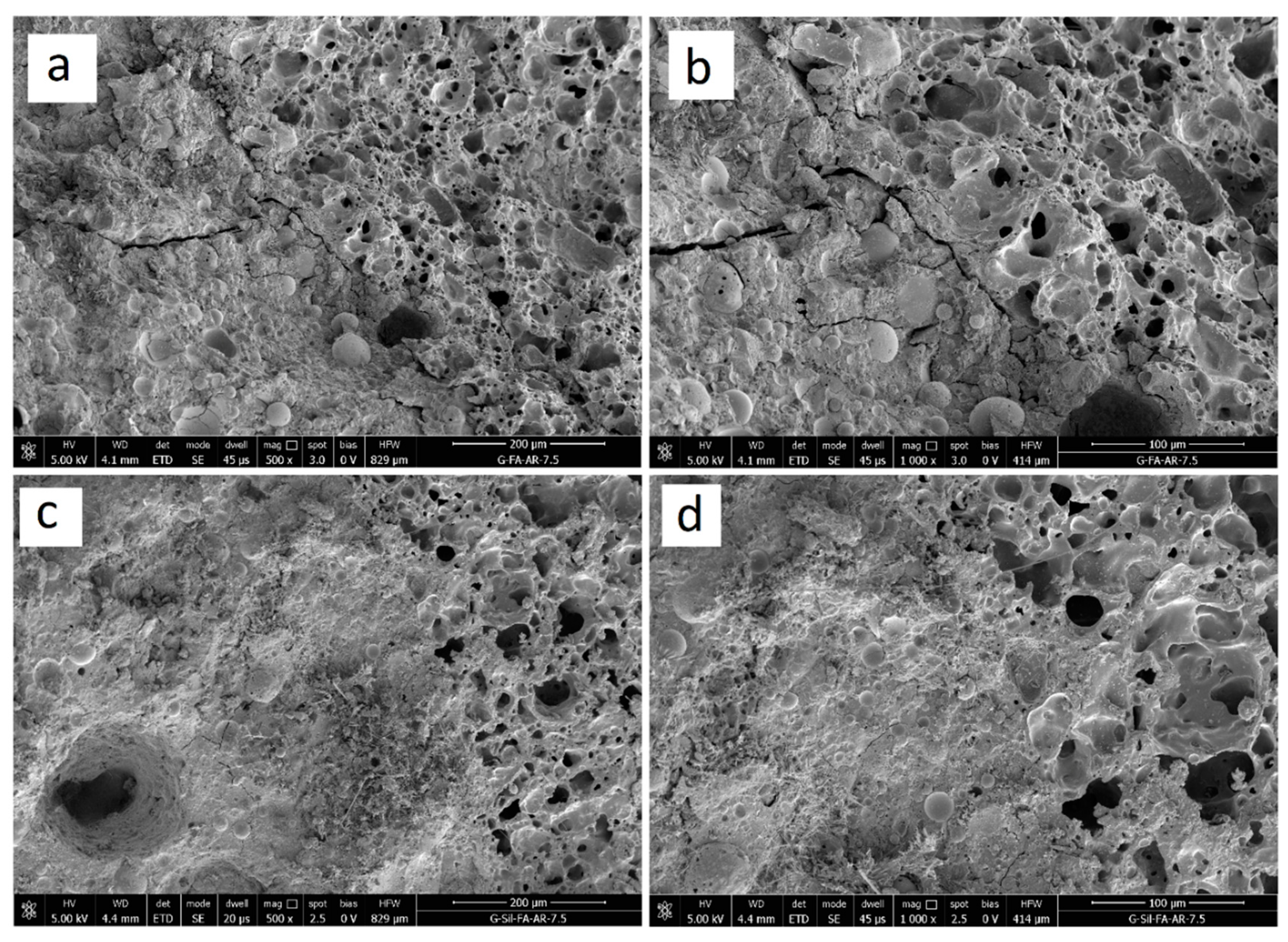
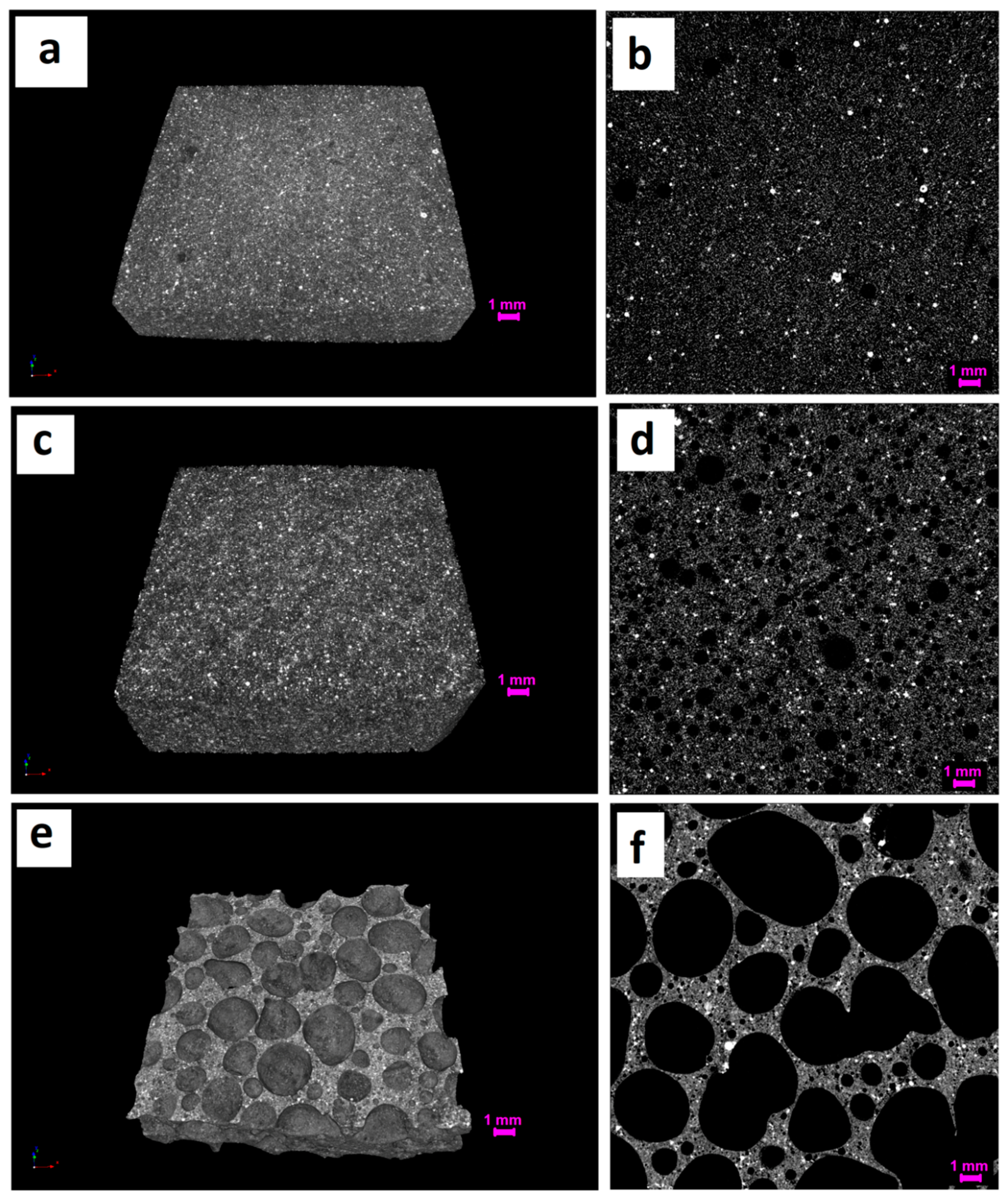
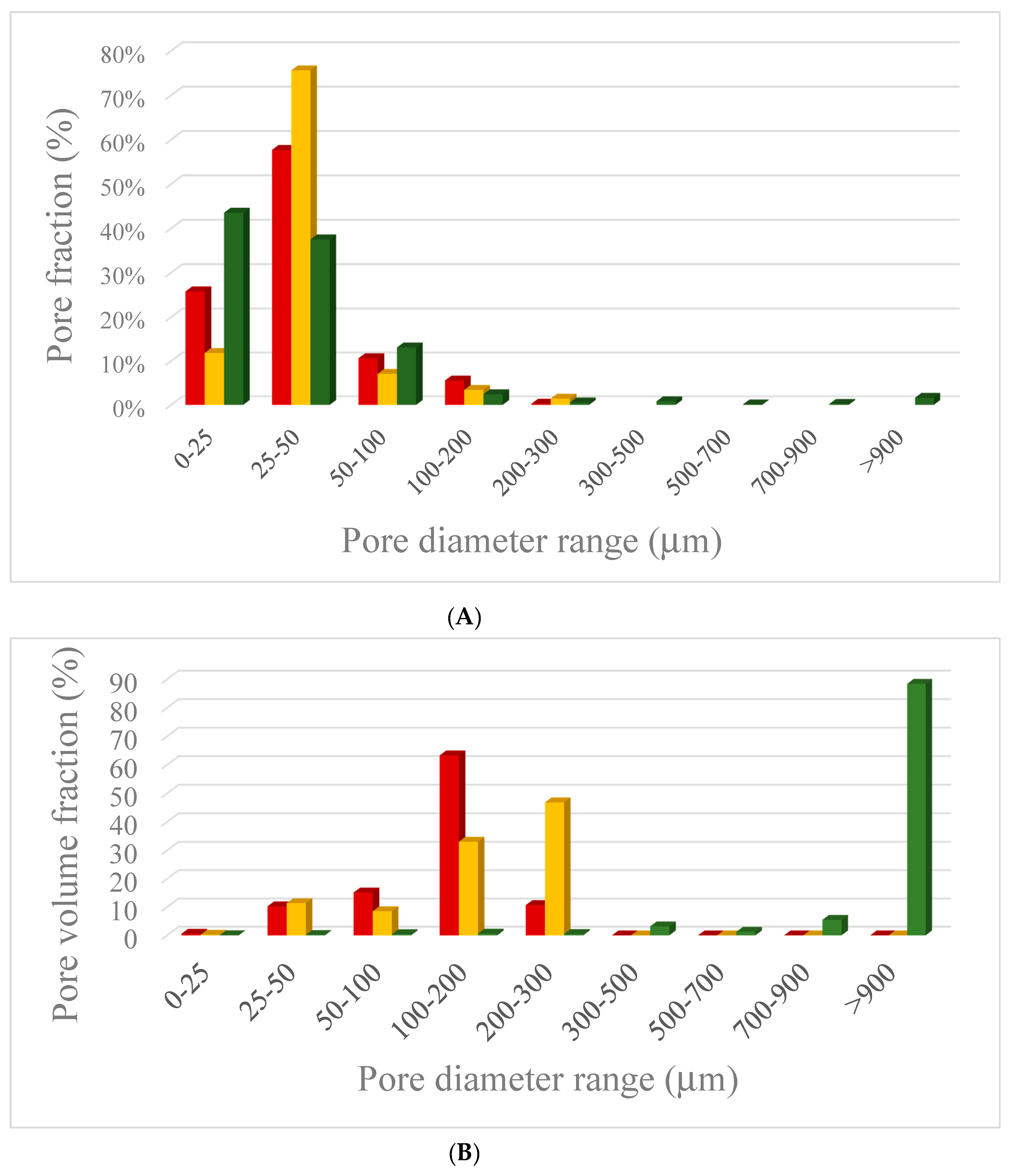
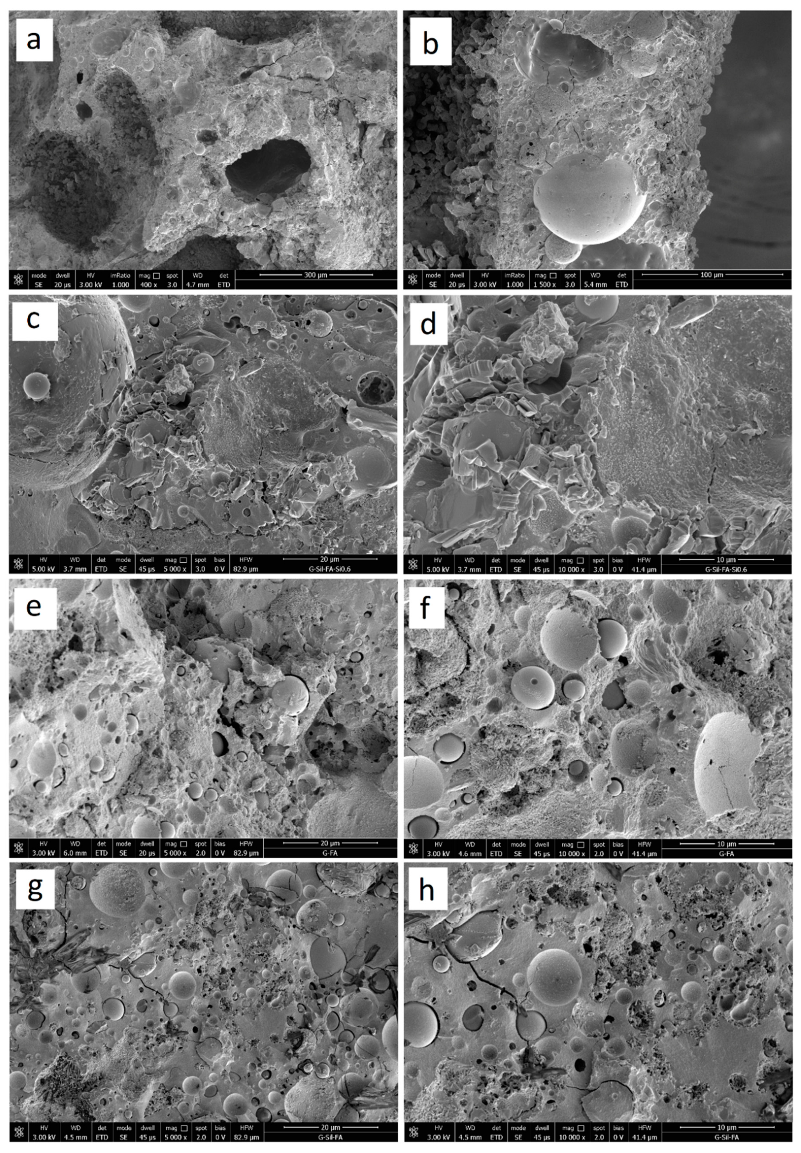
3.2. Structural Analysis
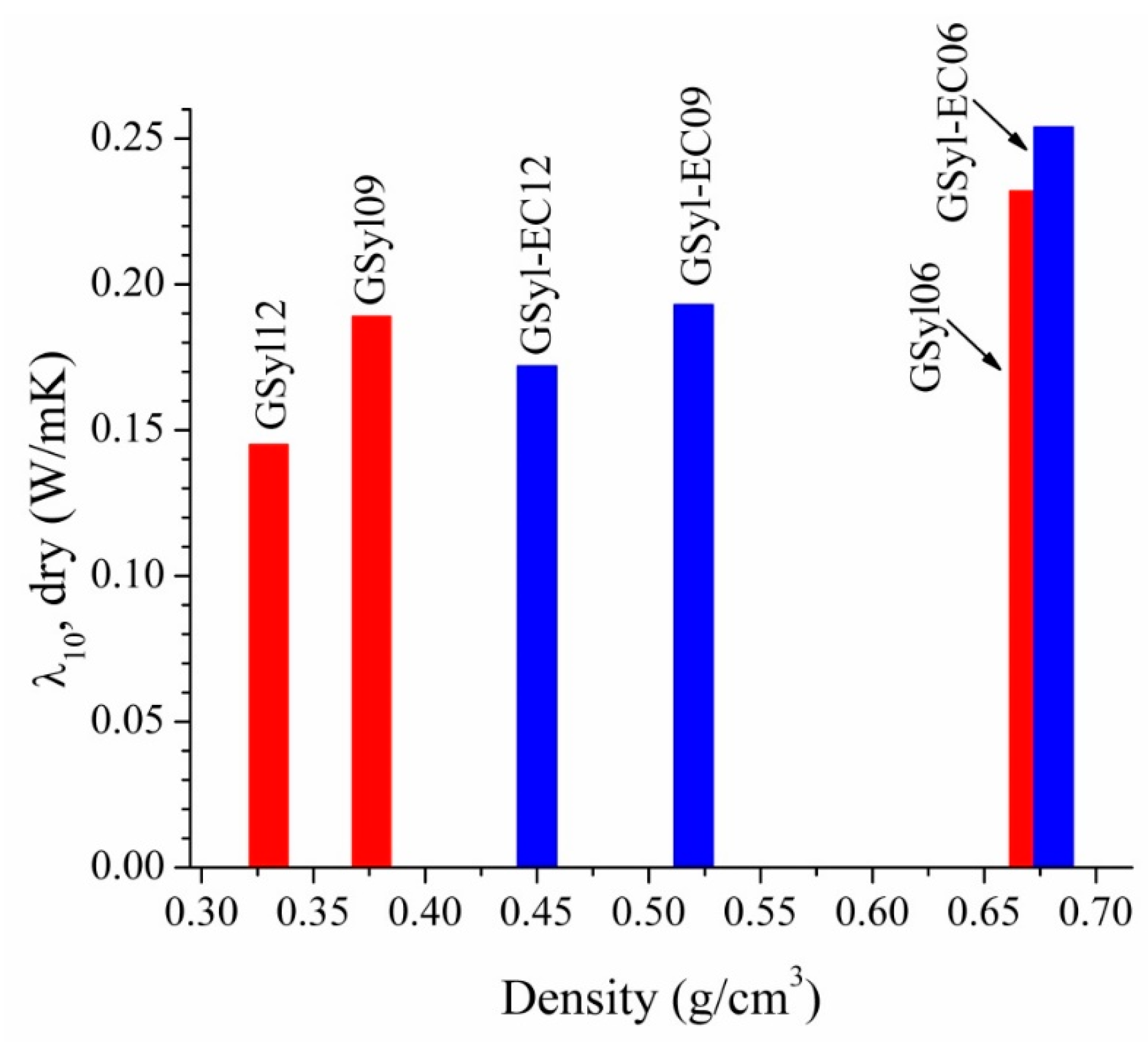
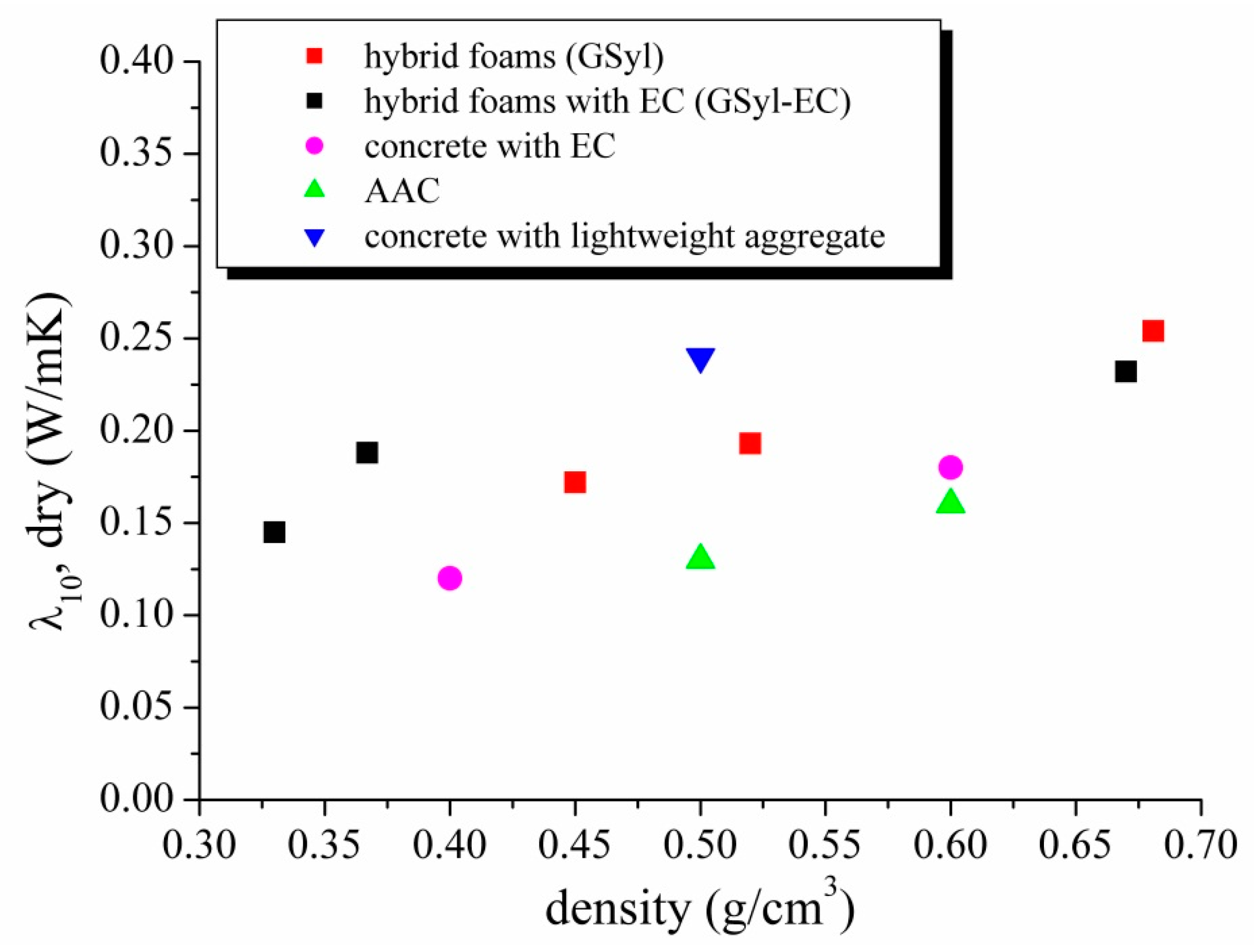
3.3. Thermal Conductivity
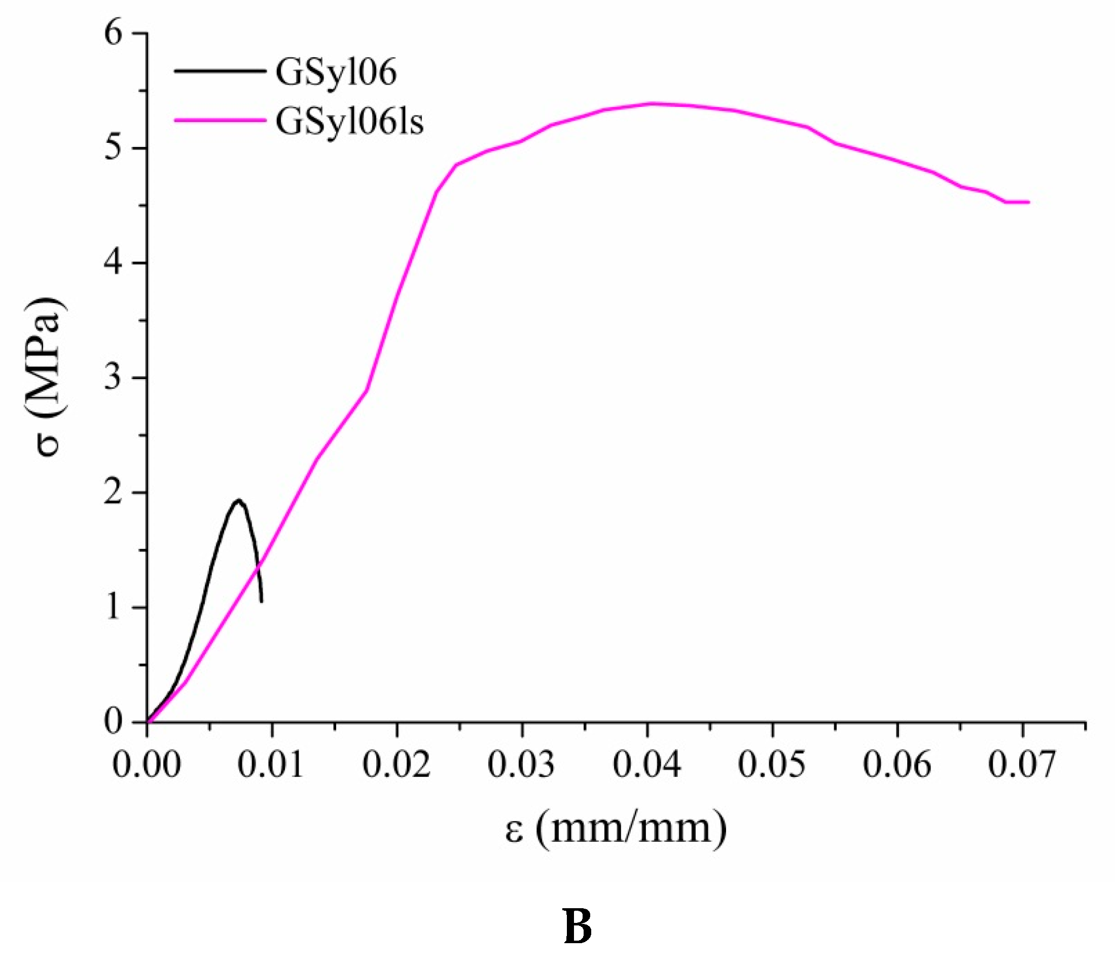
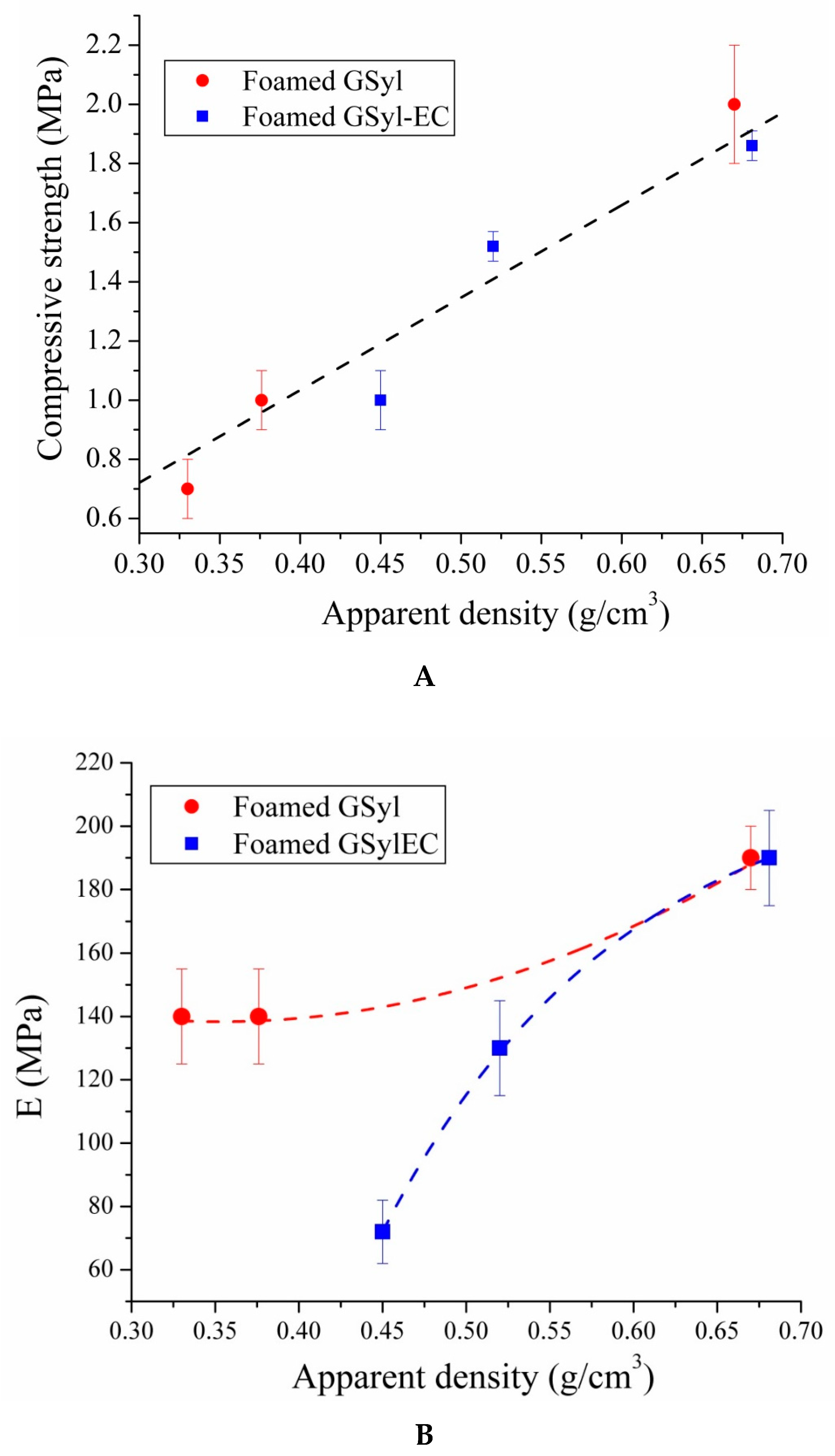
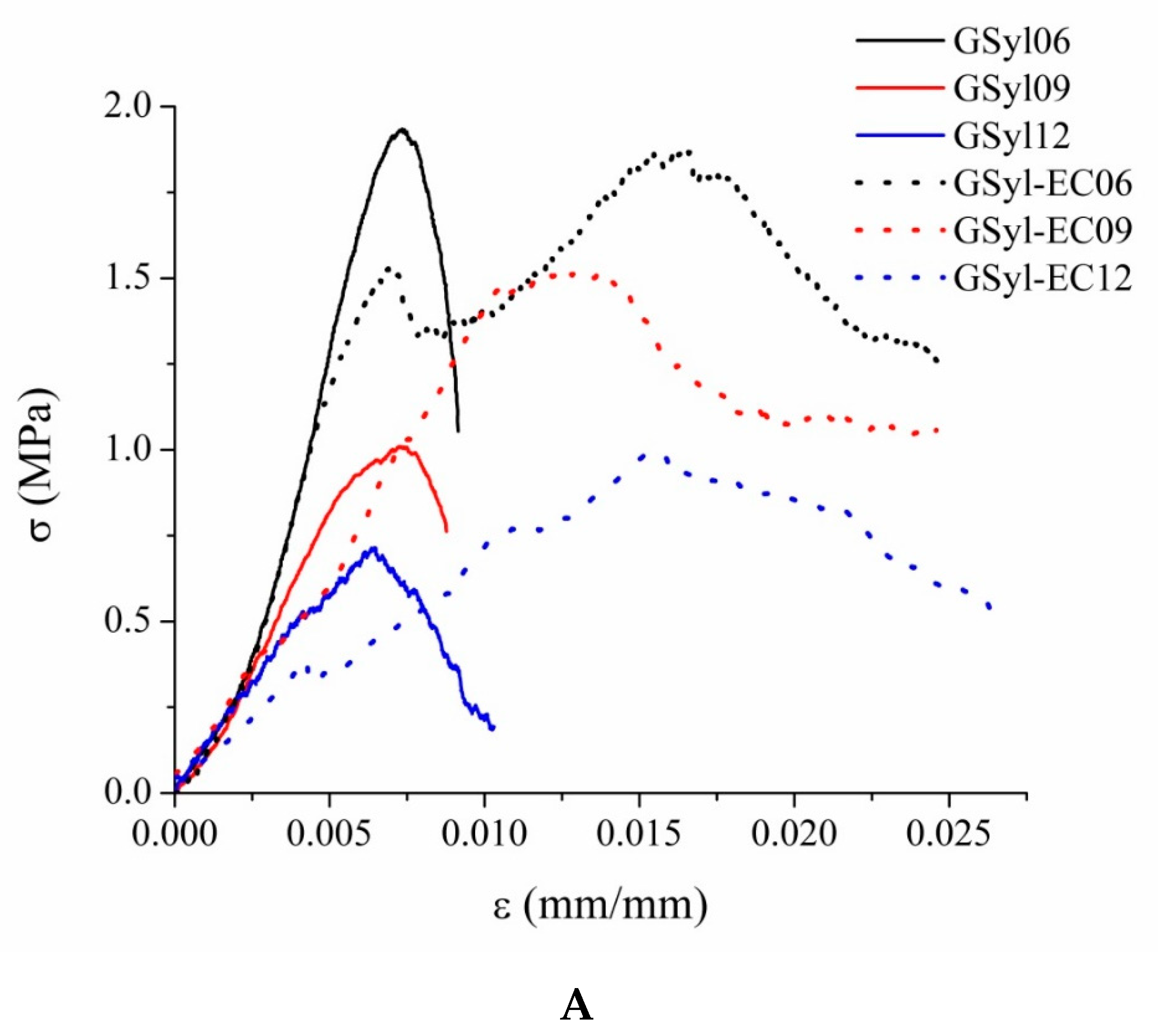
3.4. Mechanical Properties
4. Conclusions
Author Contributions
Funding
Acknowledgments
Conflicts of Interest
References
- Smart Cities Stakeholder Platform, Advanced Materials for Energy Efficient Buildings, European Technology Platform for Sustainable Chemistry. Available online: https://eu-smartcities.eu/sites/default/files/2017-0/Advanced%20Materials%20for%20Energy%20Efficient%20Buildings%20-%20Smart%20Cities%20Stakeholder%20Platform.pdf (accessed on 28 June 2019).
- Flammability Testing of Materials Used in Construction; Apte, V.B. (Ed.) Woodhead Publishing: Cambridge, UK, 2006. [Google Scholar]
- Coppola, L.; Bellezze, T.; Belli, A.; Bignozzi, M.C.; Bolzoni, F.M.; Brenna, A.; Cabrini, M.; Candamano, S.; Cappai, M.; Caputo, D.; et al. Binders alternative to Portland cement and waste management for sustainable construction—Part 1. J. Appl. Biomater. Funct. Mater. 2018, 16, 186–202. [Google Scholar] [PubMed] [Green Version]
- Coppola, L.; Bellezze, T.; Belli, A.; Bignozzi, M.C.; Bolzoni, F.; Brenna, A.; Cabrini, M.; Candamano, S.; Cappai, M.; Caputo, D.; et al. Binders alternative to Portland cement and waste management for sustainable construction—Part 2. J. Appl. Biomater. Funct. Mater. 2018, 16, 207–221. [Google Scholar] [PubMed] [Green Version]
- Environmental Product Declaration as per ISO 14025 and EN 1580 - AKG GAZBETON ISLETMELERI SAN, TIC.
- Collepardi, M. The New Concrete; Tintoretto Publishing: Loc Castrette-Treviso, Italy, 2006. [Google Scholar]
- Hussain, M.; Varely, R.; Cheng, Y.B.; Mathys, Z.; Simon, G.P. Synthesis and thermal behavior of inorganic–organic hybrid geopolymer composites. J. Appl. Polym. Sci. 2005, 96, 112–121. [Google Scholar] [CrossRef]
- Mackenzie, K.J.D.; Welter, M. Geopolymer (Aluminosilicate) Composites: Synthesis, Properties and Applications; Advances in Ceramic Matrix Composites; Woodhead Publishing Limited, Ed.; E-Publishing Inc.: Cambridge, UK, 2014; pp. 445–470. [Google Scholar]
- Duxson, P.; Fernández-Jiménez, A.; Provis, J.L. Geopolymer technology: The current state of the art. J. Mater. Sci. 2007, 42, 2917–2933. [Google Scholar] [CrossRef]
- Provis, J.L.; Jannie, S.J. Alkali Activated Materials, State-of-the-Art Report, RILEM TC 224-AAM; Provis, J., van Deventer, J., Eds.; Springer: Dordrecht, The Netherlands, 2014. [Google Scholar]
- Ferone, C.; Roviello, G.; Colangelo, F.; Cioffi, R.; Tarallo, O. Novel hybrid organic-geopolymer materials. Appl. Clay Sci. 2013, 73, 42–50. [Google Scholar] [CrossRef]
- Bassani, M.; Tefa, L.; Coppola, B.; Palmero, P. Alkali-activation of aggregate fines from construction and demolition waste: Valorisation in view of road pavement subbase applications. J. Clean. Prod. 2019, 234, 71–84. [Google Scholar] [CrossRef]
- Manini, P.; Criscuolo, V.; Ricciotti, L.; Pezzella, A.; Barra, M.; Cassinese, A.; Crescenzi, O.; Maglione, M.G.; Tassini, P.; Minarini, C.; et al. Melanin-inspired organic electronics: Electroluminescence in asymmetric triazatruxenes. ChemPlusChem 2015, 80, 919–927. [Google Scholar] [CrossRef] [Green Version]
- Roviello, G.; Ricciotti, L.; Ferone, C.; Colangelo, F.; Cioffi, R.; Tarallo, O. Synthesis and Characterization of Novel Epoxy Geopolymer Hybrid Composites. Materials 2013, 6, 3943–3962. [Google Scholar] [CrossRef] [Green Version]
- Chiarella, F.; Barra, M.; Ricciotti, L.; Aloisio, A.; Cassinese, A. Morphology, electrical performance and potentiometry of PDIF-CN2 thin-film transistors on HMDS-treated and bare silicon dioxide. Electronics 2014, 3, 76–86. [Google Scholar] [CrossRef]
- Colangelo, F.; Roviello, G.; Ricciotti, L.; Ferone, C.; Cioffi, R. Preparation and characterization of new geopolymer-epoxy resin hybrid mortars. Materials 2013, 6, 2989–3006. [Google Scholar] [CrossRef] [Green Version]
- Strini, A.; Roviello, G.; Ricciotti, L.; Ferone, C.; Messina, F.; Schiavi, L.; Cioffi, R. TiO2-Based Photocatalytic Geopolymers for Nitric Oxide Degradation. Materials 2016, 9, 513. [Google Scholar] [CrossRef] [PubMed]
- Roviello, G.; Ricciotti, L.; Ferone, C.; Colangelo, F.; Tarallo, O. Fire resistant melamine based organic-geopolymer hybrid composites. Cem. Concr. Compos. 2015, 59, 89–99. [Google Scholar] [CrossRef]
- Gottardi, S.; Toccoli, T.; Iannotta, S.; Bettotti, P.; Cassinese, A.; Barra, M.; Ricciotti, L.; Kubozono, Y. Optimizing picene molecular assembling by supersonic molecular beam deposition. J. Phys. Chem. C Nanomater. Interfaces 2012, 116, 24503–24511. [Google Scholar] [CrossRef]
- Roviello, G.; Menna, C.; Tarallo, O.; Ricciotti, L.; Ferone, C.; Colangelo, F.; Asprone, D.; di Maggio, R.; Cappelletto, E.; Prota, A.; et al. Preparation, structure and properties of hybrid materials based on geopolymers and polysiloxanes. Mater. Des. 2015, 87, 82–94. [Google Scholar] [CrossRef]
- Roviello, G.; Menna, C.; Tarallo, O.; Ricciotti, L.; Messina, F.; Ferone, C.; Asprone, D.; Cioffi, R. Lightweight geopolymer-based hybrid materials. Compos. Part B Eng. 2017, 128, 225–237. [Google Scholar] [CrossRef]
- Colangelo, F.; Roviello, G.; Ricciotti, L.; Ferrándiz-Mas, V.; Messina, F.; Ferone, C.; Tarallo, O.; Cioffi, R.; Cheeseman, C.R. Mechanical and thermal properties of lightweight geopolymer composites containing recycled expanded polystyrene. Cem. Concr. Compos. 2018, 86, 266–272. [Google Scholar] [CrossRef]
- Roviello, G.; Ricciotti, L.; Tarallo, O.; Ferone, C.; Colangelo, F.; Roviello, V.; Cioffi, R. Innovative fly ash geopolymer-epoxy composites: Preparation, microstructure and mechanical properties. Materials 2016, 9, 461. [Google Scholar] [CrossRef] [Green Version]
- Ricciotti, L.; Jacopo Molino, A.; Roviello, V.; Chianese, E.; Cennamo, P.; Roviello, G. Geopolymer Composites for Potential Applications in Cultural Heritage. Environments 2017, 4, 91. [Google Scholar] [CrossRef] [Green Version]
- Yliniemi; Paiva; Ferreira; Tiainen; Illikainen. Development and incorporation of lightweight waste-based geopolymer aggregates in mortar and concrete. Constr. Build. Mater. 2017, 131, 784–792. [Google Scholar] [CrossRef]
- Prud’homme, E.; Michaud, P.; Joussein, E.; Peyratout, C.; Smith, A.; Arrii-Clacens, S.; Clacens, J.M.; Rossignol, S. Silica fume as porogent agent in geo-materials at low temperature. J. Eur. Ceram. Soc. 2010, 30, 1641–1648. [Google Scholar] [CrossRef]
- Available online: https://www.leca.it/wp-content/uploads/2017/11/scheda_tecnica_leca_argilla_espansa.pdf (accessed on 28 June 2019).
- European Standard procedure for the determination of thermal properties of masonry and masonry products, Masonry and masonry products - Methods for determining thermal properties UNI EN 1745:2012.
- Available online: https://www.laterlite.com/products/latermix-cem-classic-4/ (accessed on 28 June 2019).
- Medri, V.; Papa, E.; Dedecek, J.; Jirglova, H.; Benito, P.; Vaccari, A.; Landi, E. Effect of metallic Si addition on polymerization degree of in situ foamed alkali-aluminosilicates. Ceram. Int. 2013, 39, 7657–7668. [Google Scholar] [CrossRef]
- Medri, V.; Ruffini, A. Alkali-bonded SiC based foams. J. Eur. Ceram. Soc. 2011, 32, 1907–1913. [Google Scholar] [CrossRef] [Green Version]
- Ferrara, G.; Coppola, B.; Di Maio, L.; Incarnato, L.; Martinelli, E. Tensile strength of flax fabrics to be used as reinforcement in cement-based composites: Experimental tests under different environmental exposures. Compos. Part B Eng. 2019, 168, 511–523. [Google Scholar] [CrossRef]


| Fly Ash | ||||||
| SiO2 | Al2O3 | Fe2O3 | MgO | K2O | Na2O | Others |
| 48.59 | 21.71 | 8.03 | 2.40 | 2.11 | 1.06 | 16.1 |
| Sodium Silicate Solution | ||||||
| SiO2 | Na2O | H2O | ||||
| 29.45 | 14.75 | 55.8 | ||||
| Sample | FA | SS | NaOH | EC | DMS | Si | Apparent Density (g/cm3) |
|---|---|---|---|---|---|---|---|
| Solid Samples | |||||||
| G | 66.17 | 24.46 | 9.37 | – | – | – | 1.662 ± 0.001 |
| G–EC | 61.20 | 22.53 | 8.67 | 7.5 | – | – | 1.562 ± 0.002 |
| GSyl | 59.55 | 22.01 | 8.44 | – | 10.0 | – | 1.471 ± 0.001 |
| GSyl–EC | 54.83 | 20.11 | 7.56 | 7.5 | 10.0 | – | 1.450 ± 0.003 |
| Foamed Samples | |||||||
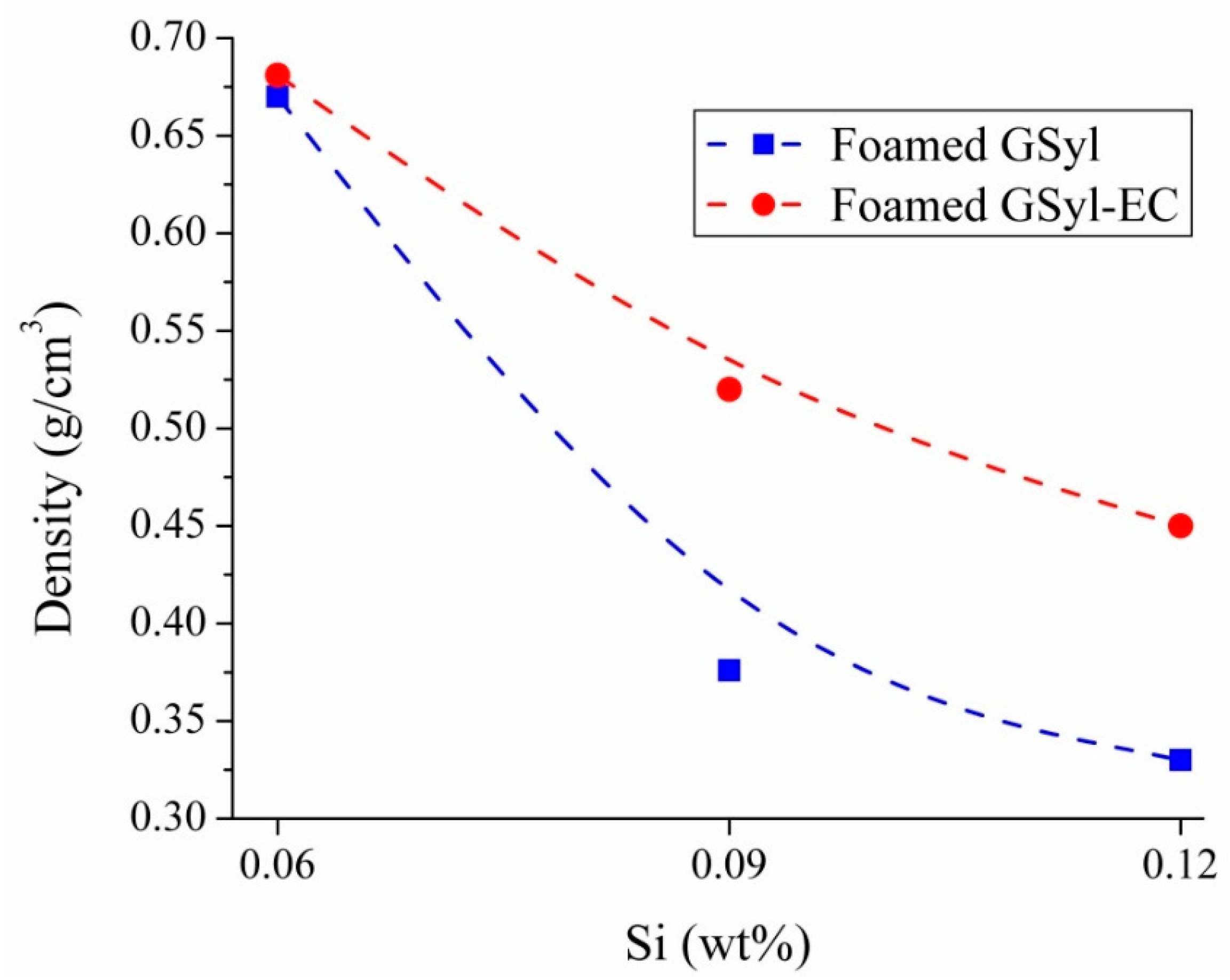
| GSyl06 | 59.55 | 22.01 | 8.44 | – | 10.0 | 0.06 | 0.670 ± 0.002 |
| GSyl09 | 59.55 | 22.01 | 8.44 | – | 10.0 | 0.09 | 0.376 ± 0.002 |
| GSyl12 | 59.55 | 22.01 | 8.44 | – | 10.0 | 0.12 | 0.330 ± 0.001 |
| GSyl–EC06 | 54.83 | 20.11 | 7.56 | 7.5 | 10.0 | 0.06 | 0.681 ± 0.003 |
| GSyl–EC09 | 54.83 | 20.11 | 7.56 | 7.5 | 10.0 | 0.09 | 0.520 ± 0.002 |
| GSyl–EC12 | 54.83 | 20.11 | 7.56 | 7.5 | 10.0 | 0.12 | 0.450 ± 0.003 |
| Sample | σc (MPa) | εc (%) | σult (MPa) | εult (%) | E (MPa) |
|---|---|---|---|---|---|
| GSyl06 | 2.0 ± 0.2 | 0.7 ± 0.1 | 1.0 ± 0.1 | 1.0 ± 0.1 | 190 ± 10 |
| GSyl09 | 1.0 ± 0.1 | 0.7 ± 0.1 | 0.8 ± 0.1 | 1.0 ± 0.2 | 140 ± 15 |
| GSyl12 | 0.7 ± 0.1 | 0.7 ± 0.02 | 0.2 ± 0.1 | 1.0 ± 0.3 | 140 ± 15 |
| GSyl06ls | 5.3 ± 0.5 | 4.3 ± 0.1 | 4.5 ± 0.2 | 7.0 ± 0.3 | 170 ± 15 |
| GSyl–EC06 | 1.86 ± 0.05 | 1.6 ± 0.1 | 1.2 ± 0.3 | 2.5 ± 0.2 | 190 ± 15 |
| GSyl–EC09 | 1.52 ± 0.05 | 1.2 ± 0.1 | 1.0 ± 0.2 | 2.4 ± 0.1 | 130 ± 10 |
| GSyl–EC12 | 1.0 ± 0.1 | 1.5 ± 0.2 | 0.5 ± 0.3 | 2.6 ± 0.3 | 72 ± 8 |
© 2020 by the authors. Licensee MDPI, Basel, Switzerland. This article is an open access article distributed under the terms and conditions of the Creative Commons Attribution (CC BY) license (http://creativecommons.org/licenses/by/4.0/).
Share and Cite
Roviello, G.; Ricciotti, L.; Molino, A.J.; Menna, C.; Ferone, C.; Asprone, D.; Cioffi, R.; Ferrandiz-Mas, V.; Russo, P.; Tarallo, O. Hybrid Fly Ash-Based Geopolymeric Foams: Microstructural, Thermal and Mechanical Properties. Materials 2020, 13, 2919. https://doi.org/10.3390/ma13132919
Roviello G, Ricciotti L, Molino AJ, Menna C, Ferone C, Asprone D, Cioffi R, Ferrandiz-Mas V, Russo P, Tarallo O. Hybrid Fly Ash-Based Geopolymeric Foams: Microstructural, Thermal and Mechanical Properties. Materials. 2020; 13(13):2919. https://doi.org/10.3390/ma13132919
Chicago/Turabian StyleRoviello, Giuseppina, Laura Ricciotti, Antonio Jacopo Molino, Costantino Menna, Claudio Ferone, Domenico Asprone, Raffaele Cioffi, Veronica Ferrandiz-Mas, Pietro Russo, and Oreste Tarallo. 2020. "Hybrid Fly Ash-Based Geopolymeric Foams: Microstructural, Thermal and Mechanical Properties" Materials 13, no. 13: 2919. https://doi.org/10.3390/ma13132919