Preparation and Characterization of Expanded Clay-Paraffin Wax-Geo-Polymer Composite Material
by
 , , and
Ahmed Hassan
1,* ,
,
Najif Ismail
2,
Abdel-Hamid I. Mourad
1,
Yasir Rashid
1 and
Mohammad S. Laghari
1 1
College of Engineering, United Arab Emirates University, P.O. Box 15551, Al Ain 15551, UAE
2
School of Engineering, Wellington Institute of Technology, Lower Hutt 5045, New Zealand
*
Author to whom correspondence should be addressed.
Materials 2018, 11(11), 2191; https://doi.org/10.3390/ma11112191
Submission received: 21 September 2018
/
Revised: 18 October 2018
/
Accepted: 22 October 2018
/
Published: 6 November 2018
Abstract
:Paraffin-based phase change material (PCM) is impregnated into the pores of lightweight expanded clay aggregate (LECA) through vacuum impregnation to develop PCM containing macro-capsules of LECA. Three different grades of LECA varying in size and morphology are investigated to host the PCM to determine the impregnation effectiveness, viability for coating, and its stability. The produced LECA-PCM is coated with geopolymer paste (GP) to provide leak proofing during the phase change. The PCM is thermophysically characterized by employing differential scanning calorimetry (DSC) and the temperature history method (THM) to determine the phase transition and the latent heat. The stability of the macro-capsules is determined by weight loss through rapid thermal cycling (RTC) at elevated temperatures. Leakage of the PCM is tested using the diffusion-oozing circle test (DOCT). The results show that the GP coated LECA-PCM macro-capsules achieved 87 wt % impregnation efficiencies and no noticeable loss of PCM, which indicates leak proofing of the developed capsules up to 1000 RTC.
1. Introduction
Phase change materials (PCMs) have been extensively studied in different configurations in buildings in order to reduce heat gain in hot climates and to store and utilize thermal energy in cold climates [1]. A computational model reported improvement in thermal performance of the building by incorporating PCM into the gypsum wallboard. The technique is viable for new as well as retrofit buildings to reduce energy consumption and the capacity requirement of the HVAC system to maintain indoor thermal comfort [2]. Application of PCM in a layered wall with the different arrangement of layers of insulation material and air cavity is also investigated. The study reported 44% reduction in the heat transmission to indoors and peak temperature shifting of 2.6 h [3]. For tropical weather conditions, a thin layer of PCM with the cool colored building envelope is proposed. This study reported energy saving in the range of 5% to 12% during the year with relatively stable weather conditions [4]. PCM plaster has been investigated in a cold climate as an internal wall and ceiling finishing material in an experimental research. Using PCM plaster, indoor temperature stabilized at almost 20 °C even when outside temperature was below −5 °C. This assembly also helped in maintaining the indoor humidity [5].
Ramakrishnan et al. extended the use of PCM to cementitious materials to improve the thermal performance of buildings. Use of PCM in cement materials applied to the building envelope can reduce peak temperature by 4.43 °C [6]. A major issue facing the PCM inclusion into the building emerged to prevent the PCM from leakage within building fabric during the phase change. Micro-encapsulation has been extensively studied as a solution to PCM by containing PCM in a stable shell material, which protects the PCM against the influences of the environment and volume changes during the phase change [7]. A comprehensive analysis of the previous studies on encapsulating PCM in different shell material employing different methods are summarized in Table 1.
Although the reviewed encapsulant materials [8,9,10,11,12,13,14,15,16,17,18,19,20,21,22,23,24,25,26] have shown success in the encapsulation efficacy, the materials possess certain limitations as it relates to their building applications. Certain materials are toxic or expensive [26,27] and fragile when subjected to shear loads in buildings [24,28] or the encapsulation processes are energy intensive [15,29]. The Geo-polymer is considered a potential encapsulant since the material preparation involves least energy inputs being fabricated through wet chemistry. Additionally, the geopolymer concrete (GPC) undergoes a phase change from a liquid-powder mix to a solid state through a non-Newtonian fluid phase during its production processes. The non-Newtonian intermediate phase can be exploited to coat the GPC over a surface and to close the surface pores to prevent leakage through the surface. Jacob et al. used Geo-polymer coating to encapsulate molten salt eutectic to mitigate the problem of corrosion of shells’ material caging salts [30]. The research was conducted for thermal energy storage for high temperature applications up to 600 °C [31,32]. The current study aims to develop thermally enhanced lightweight composite materials for building applications. The objective is achieved by encapsulating PCM into a lightweight expanded clay aggregate. Although expanded clay offers higher PCM encapsulation efficacy due to larger pore density, its performance may deteriorate rapidly due to PCM leakage through pores during the phase change. The current study identifies Geo-polymer produced from industrial waste materials and dune sand (DS) through alkali-activated polymerization as a coating material to prevent leakage of the PCM encapsulated in expanded clay. The resultant composite is evaluated for the thermal storage capacity and the thermal cycling stability for several phase change cycles.
2. Materials and Methods
Industrial waste is used in the study by activating the pozzolanic effect with the strong alkali. Materials and their preparation methods are described below.
2.1. Materials
The materials are procured from the local market and are characterized to verify the contents and phases since they would eventually affect the GPC formation. However, the impact of the content and phases on the GPC formation is not studied in this research. Microstructure is characterized by using scanning electron microscopy (SEM, JCM-5000, JEOL Limited, Tokyo, Japan) to have insight to the raw material. Thermophysical properties of the PCM are verified using differential scanning calorimetry (DSC-AT Q200, TA Instruments, New Castle, DE, USA) and temperature history method (THM). Lastly, developed capsules are tested to determine their thermal cycling stability. The list of materials used in the experimental work are presented in Table 2.
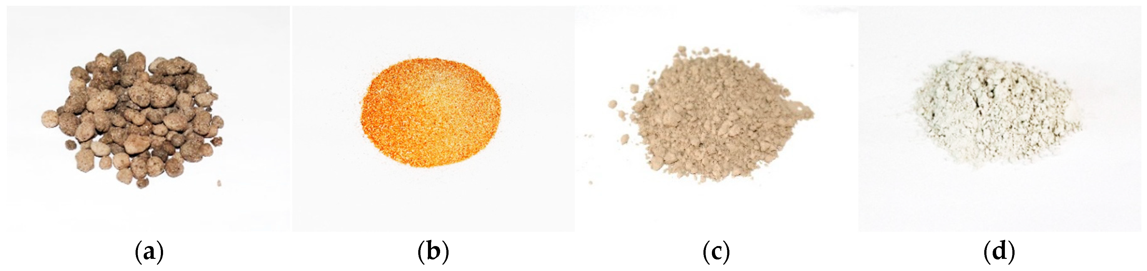
Ground granulated blast furnace slag (GGBS) and fly ash (FA) waste materials are investigated and found to form a GP by activating polymerization using a mixed solution of sodium silicate (Na2SiO3) and sodium hydroxide (NaOH). Based on the previous composition optimization [33], NaOH and Na2SiO3 were kept as 1:1.5 while the ratio of GGBS to FA to DS was fixed 1:3:6 in the geo-polymer paste composition. Three different grades of lightweight expanded clay aggregate (LECA) in terms of particle size and morphology were used. Figure 1 shows the photographs of the materials and the processes involved in the development of PCM capsules.
2.2. Materials Characterization
Materials are characterized to test their composition, microstructure, and properties. FA, GGBS, and DS are characterized by X-ray powder diffraction (XRD, PW/1840, Philips, Amsterdam, The Netherlands), X-ray fluorescence (XRF, Lab Center XRF-1800, Shimadzu Corporation, Kyoto, Japan), and SEM. PCM was characterized to evaluate its melting on-set, melting peak, melting range, and heat of fusion through DSC and THM. The schematic diagram of the experimental set-up used for THM is shown in Figure 2. DSC can accommodate a very small sample size that make it vulnerable to the inaccuracies in the results [34,35]. The problem is more pronounced in case of heterogeneous materials [36], which undergo sub cooling. The THM solves the problems faced in DSC by accommodating larger sample sizes in the range of 20 to 50 g [37]. In the current experiment, THM employed an equal mass of distilled water and PCM contained in two identical 20 cm long glass tubes with the internal diameter of 1.8 cm and a wall thickness of 1 mm. These test tube dimensions assured the Biot number is below 0.1 in order to apply the lumped capacitance heat transfer model, according to Equation (1) [38].
where hc is the convective heat transfer co-efficient, Lc is the characteristic length of the tube, and Κ is the effective thermal conductivity of the PCM and test tube material. With a system of such a small Biot number, heat transfer can be considered along the length of the wall surface when only recognizing it as the lumped capacitance method. Both test tubes were equipped with the k-type thermocouples (RS Components, Corby, UK). These thermocouples were fixed at the center point of the test tube by wrapping the wire of the thermocouple around a very thin but long insulated pin. The pin was fixed with the cork in the mouth of the tube to ensure the position of the thermocouple joint at the center. Both tubes were kept heated simultaneously at 45 °C in the heating chamber (ESPEC–Temperature and Humidity Chamber–Platninous J Series, Osaka, Japan) while the tubes were cooled by dipping into chilled water simultaneously. These thermocouples were attached to the data acquisition device (Compact DAQ (NI-cDAQ-9178), National Instruments, Austin, TX, USA) by using the module NI-9213, which was connected to the pc computer.
2.3. PCM Encapsulation
2.3.1. Immersion
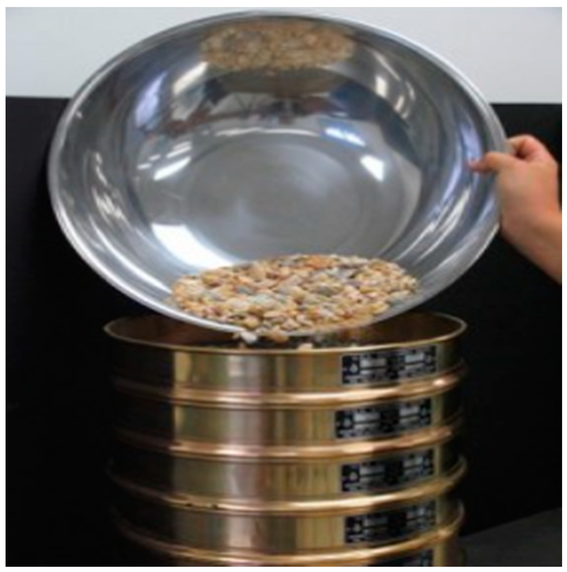
A total of 100 g of each of LECA1, LECA2, and LECA3 were immersed separately in the liquid PCM, which is shown in Figure 3. The immersion time was varied from 30 min to 24 h while keeping the temperature of the PCM at 40 °C during the test. In another trial, the PCM temperature was changed from 35 °C to 70 °C to study the effect of PCM temperature on its penetration into LECA voids. The effect of stirring after 10 min of an interval was also tested. After immersion time, the left over molten PCM was drained into the metallic sieve. The prepared LECA-PCM was dried and weight was measured to determine the amount of PCM encapsulated inside the LECA.
2.3.2. Vacuum Impregnation
Different trials of PCM impregnation were carried out to impregnate the maximum amount of PCM inside the pores of LECA. The procedure of the most effective trial is reported herein. LECA1, LECA2, and LECA3 were heated at 100 °C for 8 h to remove moisture content. The weighted amount (100 g) of the aggregates was added in the vacuum desiccator at −0.95 bar by employing a suction pump. The aggregate was spread in between two metallic sieves with a mesh size less than that of particles’ sizes to enhance surface contact between the aggregate and the PCM in a molten state. The melted PCM was injected from the top through a funnel to flow under gravity past the LECA through sieves. The PCM was kept injected inside the desiccator until the porous aggregate was fully submerged. The top sieve is installed to prevent LECA floating over the PCM surface when a vacuum is applied. The bottom sieve is installed to prevent settling of the heavier LECA-PCM mix when the vacuum is removed. The vacuum was applied for 30 min under PCM stirring once every 5 min where the vacuum desiccator was shaken to achieve the stirring. The PCM is assumed to keep impregnation into LECA as long as air bubbles keep appearing under vacuum in the melt desiccator containing LECA-PCM mix. The temperature of the mix is maintained substantially above the PCM melting point to prevent PCM solidification above the LECA surface during impregnation. The PCM temperature was maintained substantially higher than the solidification temperature to prevent PCM solidification within pores during impregnation to assure maximal encapsulation.
2.3.3. Coating
A total of 18 molar NaOH solutions were blended with the Na2SiO3 solution and shake well for five minutes to assure solution homogenization. The mixing ratios and solution molarities being applied in the current research were reported to achieve a maximum compressive strength [33]. Due to the exothermic nature of the reaction, the heated solution was kept for one day in ambient conditions to cool down prior to being poured into a dry mix of FA, GGBS, and DS. The FA, GGBS, and DS powders were mixed and homogenized in a steel container by using a mechanical stirrer simultaneously. Alkali solution was poured into the powder mix to develop GP paste. Macro capsules of LECA-PCM were added to the GP paste in the concrete mixer (Namson Trading GmbH, Frankfurt, Germany) to apply a GP layer around the LECA-PCM particles. As soon as the hardening of the GP layer started over the LECA-PCM surface, the macro capsules were taken out of the concrete mixer. The LECA-PCM capsules were rolled over a bench until complete hardening of the GP paste occurred. An illustration of the steps involved in the process are shown in Figure 4.
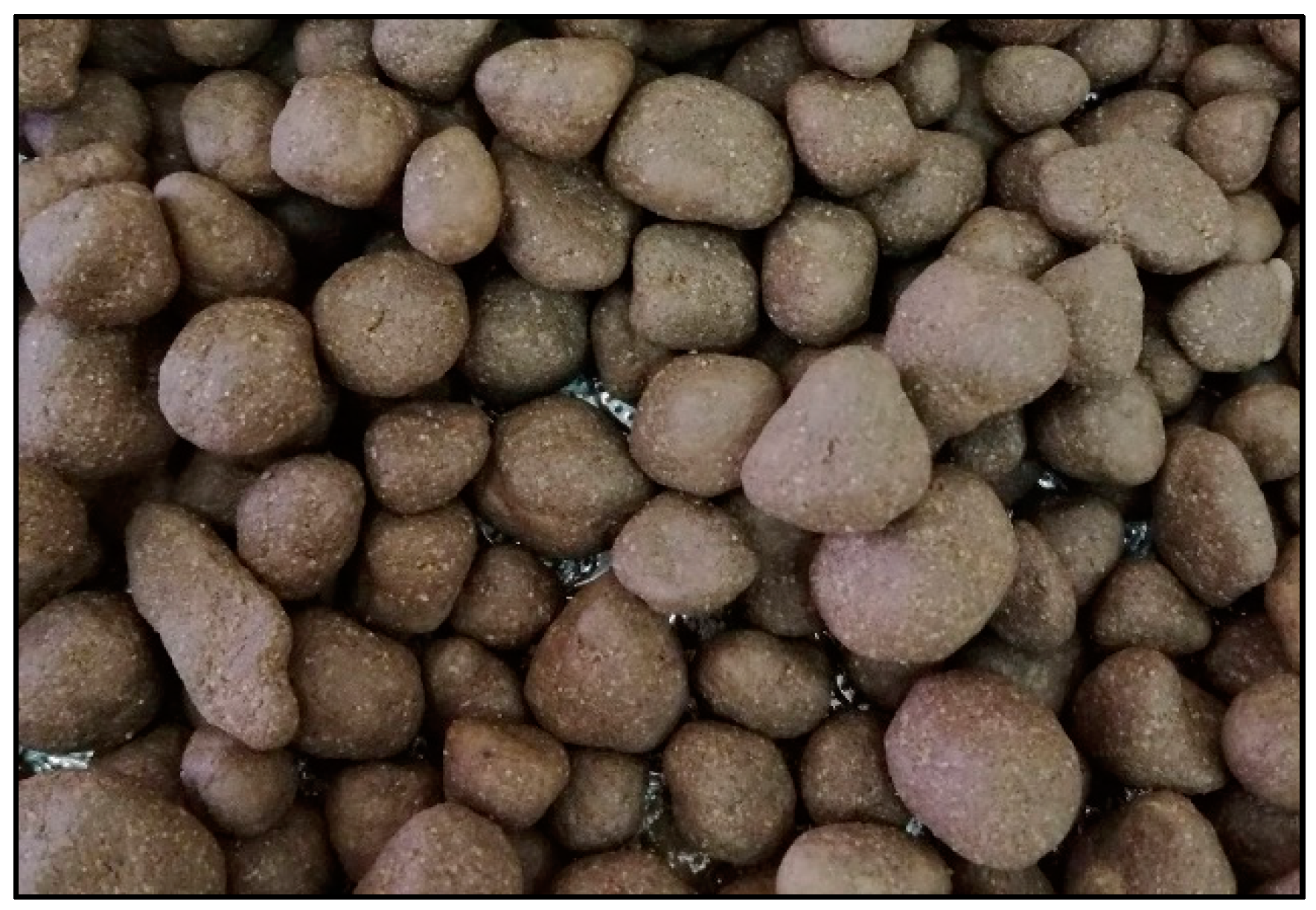
The rolling of a spherical aggregate filled with PCM into the geo-polymer paste produced spherical capsules. The process yielded a GP-coated form stable LECA-PCM macro-capsules, which is shown in Figure 5. Newly produced capsules were kept at room temperature for 24 h for curing.
2.4. Testing of Thermal Stability
2.4.1. Weathering Test
GP-coated LECA-PCM capsules were kept outdoors for 60 days with temperatures fluctuating above and below the melting point of PCM to visually observe degradation of coating under solar radiation and temperature cycles. The ambient temperature fluctuated between 38 °C and 23 °C during the daytime and nighttime of the test duration.
2.4.2. Controlled Indoor Test
The capsules were tested under RTC in a heating chamber (ESPEC–Temperature and Humidity Chamber–Platninous J Series, Osaka, Japan), which is shown in Figure 6. The temperature fluctuations during RTC were from 10 °C to 105 °C. The samples were kept in a perforated containment to let any produced vapors escape and this counted as weight loss. The samples were subjected to 1000 RTC and the weight was measured after 100 cycles along with visual observation to determine the apparent wetting of the surface.
2.4.3. Diffusion-Oozing Circle Test
A DOCT was conducted to check the leakage of PCM out of GP-LECA-PCM capsules by following the method proposed in Reference [39]. In the test, a circle of 30 mm diameter was plotted on a filter paper and capsules of GP-LECA-PCM were placed inside the circle. It was heated up to 105 °C inside the heating chamber so that inside PCM can melt completely. After cooling it to a normal temperature, the capsules were removed and the circle was measured again. Leakage was measured by using Equation (2) [40].
where the value of η will decide the leakage performance of the material, D is the diameter of the circle with the subscripts of LK representing the leakage circle and SD for the standard circle.
3. Results
Leak proofing of the GP-LECA-PCM capsules is the most important parameter of investigation. The results for impregnation efficiency, DSC, THM, RTC, and DOCT are presented below.
3.1. Composition and Microstructure of the Materials
3.1.1. X-ray Diffraction Analysis
The dry constituent materials were grounded to a fine powder and x-ray diffraction analysis was conducted with a Cu-Kα radiation at room temperature. The prepared samples were scanned at 2θ between 10° and 80°. The experimentally obtained X-ray diffractograms are shown in Figure 7.
The large halo located between 25° and 35° (2θ) in the X-ray diffractogram of GGBS (Figure 7a) indicates that it contains mostly amorphous compounds. The amorphous composition of GGBS is due to the quenching process where water is used during its production. Small reflections for Quartz (SiO2), Mullite (Al6Si2O13), and Gehlenite (Ca2Al(AlSiO7)) were also identified. Figure 7b displays the X-ray diffractogram of fly ash, which revealed several sharp crystalline peaks in 2θ range from 20° and 70°. The observed sharp crystalline peaks were assigned to the main crystalline phases of Quartz (SiO2), Mullite (Al6Si2O13), and Hematite (Fe2O3). The presence of these relatively inactive crystalline phases is typical in low-calcium flay ash. The wide diffusive hump shows the presence of a small quantity of amorphous solids as well. The ground LECA powder showed phase composition similar to that expected for autoclaved clays (Figure 7c). Quartz (SiO2) was the major crystalline phase identified in the dune sand (Figure 7d) with other minor phases identified to include Calcite (CaCO3), Dolomite (CaMg(CO3)2), Mullite (3Al2O32SiO2), and Hematite (α-Fe2O3).
3.1.2. Scanning Electron Microscopy Analysis
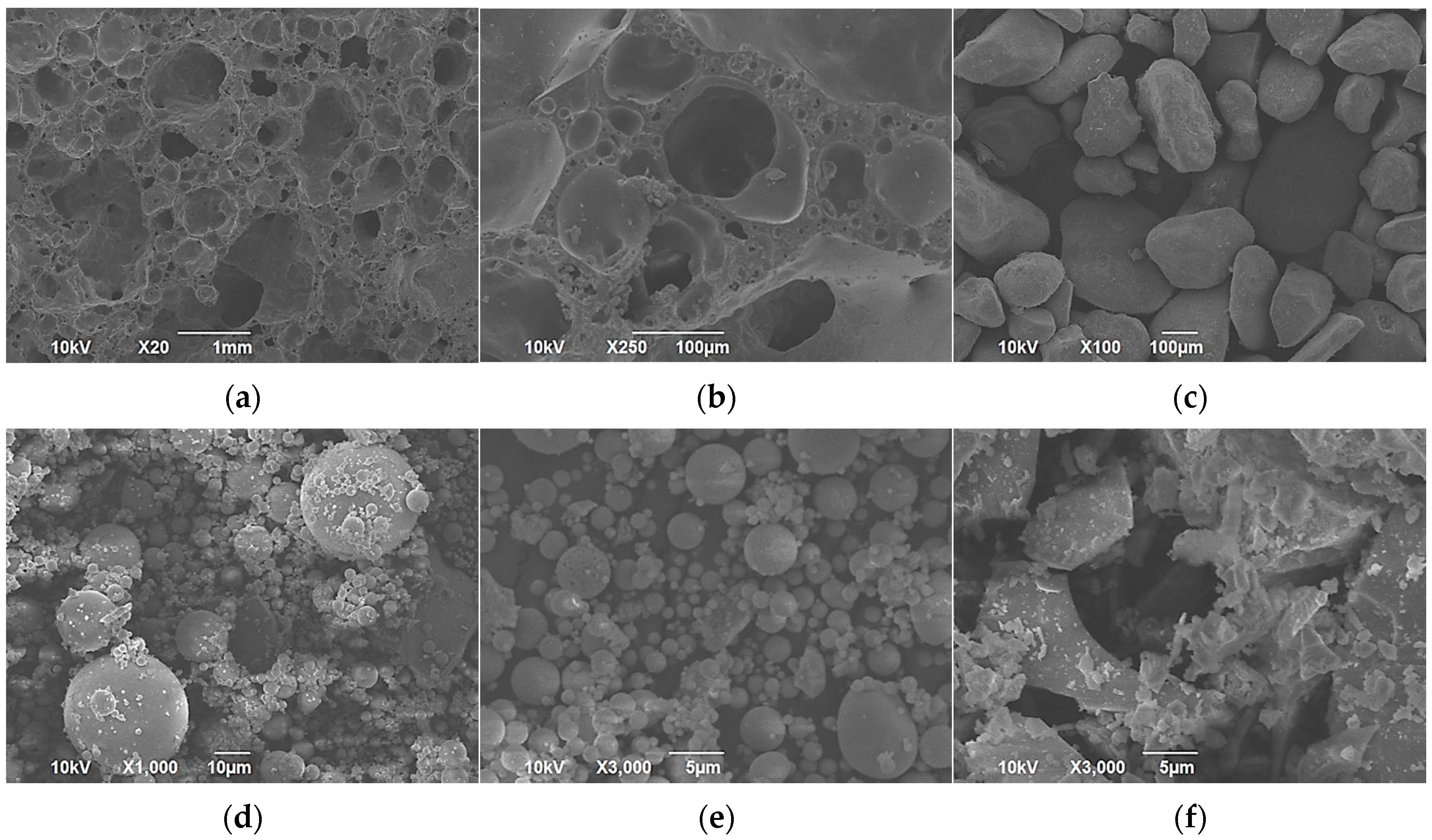
The scanning electron microscopic (SEM) analysis was carried out by using accelerating voltages of 10 kV and 15 kV. Interconnected porosity of LECA can be observed in Figure 8a,b. The pore size was not uniform and ranged from a few μm to almost 1 mm. This porosity can be installed in buildings for thermal insulation, sound proofing, and lightness of concrete. This research exploited its ability to host PCM in its porosity because of its interconnected type. A microstructure of DS was noted to be nodular with the size range approximately 80 μm to 200 μm (Figure 8c). SEM investigation of FA revealed that its particles were spherical in shape and mainly smaller than 30 μm (Figure 8d) but had a broad particle size distribution (Figure 8e). GGBS particles were noted to have different microstructures (Figure 8f) i.e., coarser than fly ash and were angular in structure with a mean particle size of about 27 μm.
Detailed SEM and EDX analysis of the geo-polymer paste has been reported by authors in a precedent study [33] and key findings are reported here for relevance. Figure 9 shows the micrograph of the geo-polymer. It can be observed that FA spheres were intermixed with angular slag particles and reaction products can adhere to the surface of FA spheres. To further characterize the reaction products, energy dispersive X-ray (EDX) spot analysis was employed. The EDX plot highlighted the presence of calcium (Ca), silicon (Si), sodium (Na), aluminum (Al), and oxygen (O). This indicated that an aluminium-modified C–S–H gel co-existed with an N–A–S–H geopolymer gel. A silicon-to-aluminum (Si/Al) ratio of 1.80 was reported in the aluminosilicate phase.
3.1.3. X-ray Fluorescence Analysis
3.2. Thermo-Physical Properties of PCM
3.2.1. Differential Scanning Calorimetry
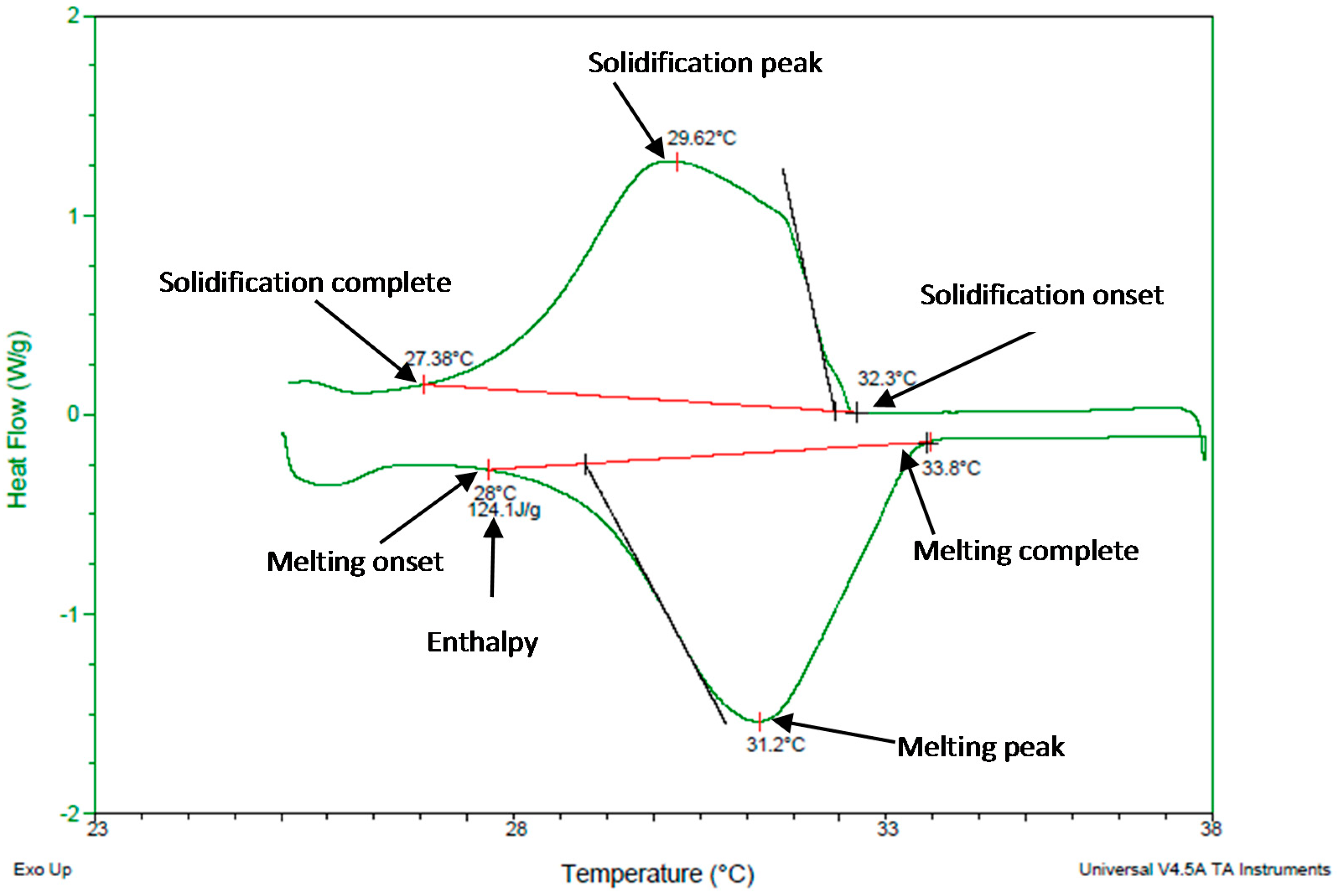
Figure 10 shows the DSC thermogram of a 5-mg PCM sample at a scanning rate of 1 °C/min. The heating run shows that heat absorption starts at 28 °C and is completed at 33.8 °C with the peak at 31.2 °C with a heat of fusion of 124.1 J/g. The cooling run shows that solidification started at 32.3 °C and completed at 27.38 °C with the peak at 29.62 °C. DSC results agree with the manufacturer’s catalogue melting points of 27–33 °C while it substantially disagrees with the solidification range of 33–27 °C [42].
3.2.2. Temperature History Method
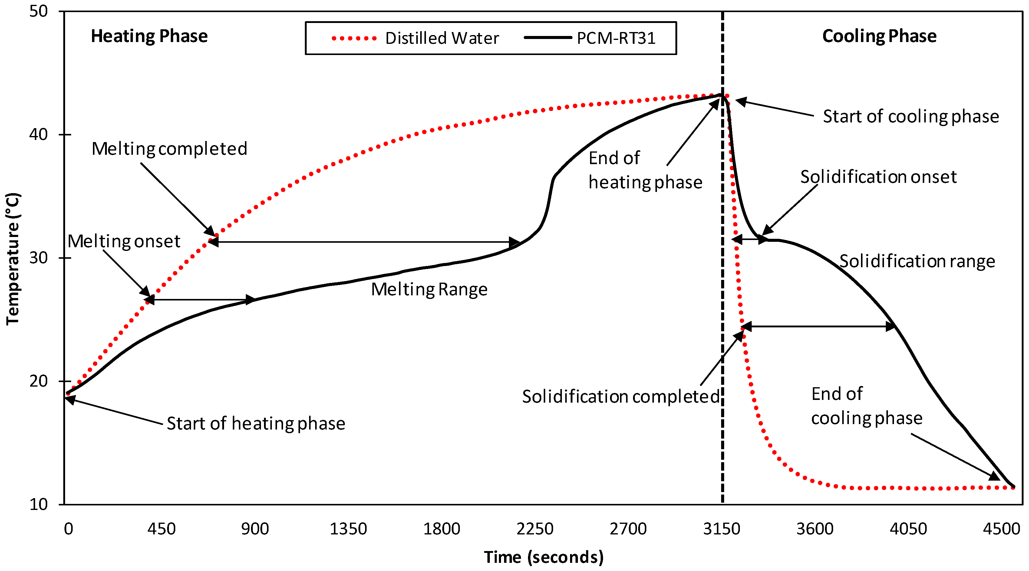
The THM results slightly disagrees with the DSC in melting and solidification temperatures possibly due to the hysteresis nature of the material and thermal gradient inside the PCM sample [34] or the uncertainty in the measuring instruments [43]. In THM, the end of melting in the heating phase and solidification onset in the cooling phase were almost the same at 32 °C as shown in Figure 11. During heating, it represents a delay in the PCM temperature rise when compared to distilled water due to its higher heat of fusion. The melting initiated at 27 °C and completed at 32 °C was represented by a drop in the temperature gradient, which indicates latent heat absorbed by the PCM. In comparison, the temperature rise for water is consistent and uniform. The difference in the gradient of the temperature rise of the materials is also visible in the cooling regime. It represents a delay in the cooling of PCM as compared to water due to higher heat release of the PCM during its phase transition. For the cooling phase, solidification started at 33 °C and was completed at 26.5 °C. The heating phase was completed in almost 3150 seconds while cooling required 1350 s. The difference in time required is due to different heating and cooling rates in both phases. Quenching of both tubes in cold water at 10 °C enhanced the cooling rate, which resulted in rapid cooling and a sharp curve when compared to the heating phase.
3.3. Impregnation Efficiency
3.3.1. Immersion
There was no observable difference in weight gain of the aggregate and consequently no impregnation. Therefore, the immersion technique is not effective and should not be used.
3.3.2. Vacuum Impregnation
The size of the LECA particle and its morphology have a marginal effect on its absorption efficiency. The crushing of the particles of LECA2 and LECA3 slightly increased the PCM absorption from 83 wt % to 87 wt %. This increment may be attributed to the utmost filling of pores because the surface treatment of LECA was removed when crushed. For further investigations, crushed particles and LECA3 were not considered because they could not be rolled in the GP paste due to irregular morphology. In the best case, a maximum of 87 wt % was achieved in LECA1 but a smaller size of the LECA caused agglomeration while coating with GP. Therefore, LECA2 were finalized for further research because of comparable absorption of 83 wt %, which is a suitable size and regular shape for GP coating. In a study, only 31 wt % was impregnated into LECA using vacuum impregnation [44,45]. Yet, Na2SiO3 was impregnated with the density at much higher levels than that of PCM. Absorption efficiency is important for a compact but dense thermal energy storage system. The higher the quantity, PCM is filled in the pores of the same LECA as compared to the smaller quantity required when used in the building components for thermal energy management. Therefore, by developing denser particles and using less quantity, it will generate the same thermal effects and less compromised structural strength.
3.4. Thermal Stability
3.4.1. Weather and Rapid Thermal Cycling
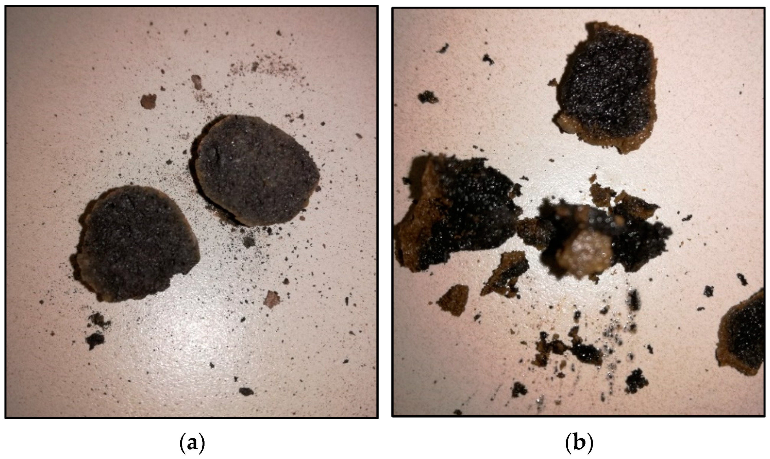
Thermal stresses may induce cracks or rupture on the coating layer. No apparent sign of leakage or rupture was observed over the GP coated LECA-PCM surface indicating the durability of the coating. To validate the presence of PCM inside the GP-LECA-PCM, a capsule at the high temperature was crushed with a high impact load. A good amount of PCM was observed inside the GP shell in a molten form, which is shown in Figure 12. This confirms the longevity of the coating material. Two different types of expanded clay aggregates have been investigated for PCM absorption to develop thermal energy storage concrete. Although the reported value for the PCM absorption is 89.8% at the maximum, the investigation included only the weight loss method to test the thermal stability in a narrow range of thermal cycles between 10 °C to 60 °C [46]. The study has limitations because, at an even higher temperature, materials will behave differently because of the mismatch of volume changes of PCM, the aggregate, and its coating. Aguayo et al. used four different types of LECA to host PCM and achieved 21.2% PCM absorption efficiency at the maximum. The study investigated cement-based insulation to reduce the insulation layer thickness with the dampened temperature peaks [47].
3.4.2. Diffusion-Oozing Circle Test
The test claims that the maximum of 15% increase in the diameter of the circle is acceptable for leakage of PCM out of the porous media [48]. Results of our study revealed there was absolutely no increase in the ooze circle, which indicated the perfect leak proofing of the capsules. Figure 13 shows the filter paper with and without GP-LECA-PCM capsules on its surface after exposing it to higher temperatures. Hence, the materials and methods can be used for leak proofing of PCMs contained in the porous media.
4. Conclusions
A paraffin based PCM is characterized through DSC and THM for building integration aimed at enhancing the thermal performance of buildings. The material exhibited a reasonable thermal energy storage capacity of 124.1 J/g with a phase transition temperature of 28 °C being close to a human thermal comfort. The PCM is macro-encapsulated into porous lightweight expanded clay aggregate (LECA) by vacuum impregnation to form LECA-PCM composite capsules. A low porosity Geo-polymer paste is prepared through alkali-activated polymerization of fly ash, glass slag, and dune sand and applied to LECA-PCM surface by mechanically rolling capsules over the paste. The paste forms a uniform layer that hardens over the LECA-PCM surface and fills the open pores, which forms a leak proof layer that prevents PCM leakage during the liquid phase. Thermal cycling durability of the leak proof layer is tested both under an indoor temperature change of 15 °C to 105 °C and outdoor temperatures irradiated by solar radiation undergoing a temperature change of 23 °C to 65 °C. The protective coating remained intact for the tested duration showing no obvious surface wetting as well as weight loss. It is, therefore, concluded that the Geo-polymer coating is effective at preventing the leakage of macro-encapsulated PCMs contained in a porous shell under extreme indoors and outdoors conditions for limited thermal cycles. The durability of the leak proof layer still needs to tested for longer exposure times in a range of several years through rapid thermal cycling indoors and outdoors.
Author Contributions
The project was “Conceptualized” by A.H. and N.I. N.I. and A.H. designed the methodology. A.-H.I.M. and N.I. conducted the formal analysis. Y.R. performed the investigation and wrote the original draft. A.H. and M.S.L. secured the funding and administered the project.
Funding
This research was funded by the Program for Advanced Research (31N204-UPAR-5-2014).
Acknowledgments
The authors would like to express their appreciation to United Arab Emirates University (UAEU) for funding the research through the Program for Advanced Research (31N204-UPAR-5-2014) and the Faculty of Engineering at the UAE University to facilitate experimentation.
Conflicts of Interest
The authors declare no conflict of interest.
References
- Hassan, A.; Shakeel Laghari, M.; Rashid, Y. Micro-Encapsulated Phase Change Materials: A Review of Encapsulation, Safety and Thermal Characteristics. Sustainability 2016, 8, 1046. [Google Scholar] [CrossRef]
- Sharifi, N.P.; Shaikh, A.A.N.; Sakulich, A.R. Application of phase change materials in gypsum boards to meet building energy conservation goals. Energy Build. 2017, 138, 455–467. [Google Scholar] [CrossRef]
- Hasan, A.; Al-Sallal, K.; Alnoman, H.; Rashid, Y.; Abdelbaqi, S. Effect of Phase Change Materials (PCMs) Integrated into a Concrete Block on Heat Gain Prevention in a Hot Climate. Sustainability 2016, 8, 1009. [Google Scholar] [CrossRef]
- Lei, J.; Kumarasamy, K.; Zingre, K.T.; Yang, J.; Wan, M.P.; Yang, E.-H. Cool colored coating and phase change materials as complementary cooling strategies for building cooling load reduction in tropics. Appl. Energy 2017, 190, 57–63. [Google Scholar] [CrossRef]
- Kusama, Y.; Ishidoya, Y. Thermal effects of a novel phase change material (PCM) plaster under different insulation and heating scenarios. Energy Build. 2017, 141, 226–237. [Google Scholar] [CrossRef]
- Ramakrishnan, S.; Wang, X.; Sanjayan, J.; Wilson, J. Thermal performance assessment of phase change material integrated cementitious composites in buildings: Experimental and numerical approach. Appl. Energy 2017, 207, 654–664. [Google Scholar] [CrossRef]
- Li, M.G.; Zhang, Y.; Xu, Y.H.; Zhang, D. Effect of different amounts of surfactant on characteristics of nanoencapsulated phase-change materials. Polym. Bull. 2011, 67, 541–552. [Google Scholar] [CrossRef]
- Tang, B.; Cui, J.; Wang, Y.; Jia, C.; Zhang, S. Facile synthesis and performances of PEG/SiO2 composite form-stable phase change materials. Sol. Energy 2013, 97, 484–492. [Google Scholar] [CrossRef]
- Giro-Paloma, J.; Konuklu, Y.; Fernández, A.I. Preparation and exhaustive characterization of paraffin or palmitic acid microcapsules as novel phase change material. Sol. Energy 2015, 112, 300–309. [Google Scholar] [CrossRef]
- Konuklu, Y.; Paksoy, H.Ö. Polystyrene-based caprylic acid microencapsulation for thermal energy storage. Sol. Energy Mater. Sol. Cells 2017, 159, 235–242. [Google Scholar] [CrossRef]
- Kahraman Döğüşcü, D.; Kızıl, Ç.; Biçer, A.; Sarı, A.; Alkan, C. Microencapsulated n-alkane eutectics in polystyrene for solar thermal applications. Sol. Energy 2018, 160, 32–42. [Google Scholar] [CrossRef]
- Zhang, G.H.; Bon, S.A.F.; Zhao, C.Y. Synthesis, characterization and thermal properties of novel nanoencapsulated phase change materials for thermal energy storage. Sol. Energy 2012, 86, 1149–1154. [Google Scholar] [CrossRef]
- Ma, Y.; Chu, X.; Li, W.; Tang, G. Preparation and characterization of poly(methyl methacrylate-co-divinylbenzene) microcapsules containing phase change temperature adjustable binary core materials. Sol. Energy 2012, 86, 2056–2066. [Google Scholar] [CrossRef]
- Guo, X.; Cao, J.; Peng, Y.; Liu, R. Incorporation of microencapsulated dodecanol into wood flour/high-density polyethylene composite as a phase change material for thermal energy storage. Mater. Des. 2016, 89, 1325–1334. [Google Scholar] [CrossRef]
- Feczkó, T.; Kardos, A.F.; Németh, B.; Trif, L.; Gyenis, J. Microencapsulation of n-hexadecane phase change material by ethyl cellulose polymer. Polym. Bull. 2014, 71, 3289–3304. [Google Scholar] [CrossRef] [Green Version]
- Li, J.; Lu, W.; Luo, Z.; Zeng, Y. Synthesis and thermal properties of novel sodium nitrate microcapsules for high-temperature thermal energy storage. Sol. Energy Mater. Sol. Cells 2017, 159, 440–446. [Google Scholar] [CrossRef]
- Qiu, X.; Lu, L.; Zhang, Z.; Tang, G.; Song, G. Preparation, thermal property, and thermal stability of microencapsulated n-octadecane with poly(stearyl methacrylate) as shell. J. Therm. Anal. Calorim. 2014, 118, 1441–1449. [Google Scholar] [CrossRef]
- Zhang, J.; Zhao, T.; Chai, Y.; Wang, L. Preparation and Characterization of High Content Paraffin Wax Microcapsules and Micro/Nanocapsules with Poly Methyl Methacrylate Shell by Suspension-Like Polymerization. Chin. J. Chem. 2017, 35, 497–506. [Google Scholar] [CrossRef]
- Yang, Y.; Kuang, J.; Wang, H.; Song, G.; Liu, Y.; Tang, G. Enhancement in thermal property of phase change microcapsules with modified silicon nitride for solar energy. Sol. Energy Mater. Sol. Cells 2016, 151, 89–95. [Google Scholar] [CrossRef]
- Zhang, Y.; Wang, L.; Tang, B.; Lu, R.; Zhang, S. Form-stable phase change materials with high phase change enthalpy from the composite of paraffin and cross-linking phase change structure. Appl. Energy 2016, 184, 241–246. [Google Scholar] [CrossRef]
- Karaman, S.; Karaipekli, A.; Sarı, A.; Biçer, A. Polyethylene glycol (PEG)/diatomite composite as a novel form-stable phase change material for thermal energy storage. Sol. Energy Mater. Sol. Cells 2011, 95, 1647–1653. [Google Scholar] [CrossRef]
- Sarı, A.; Bicer, A.; Al-Sulaiman, F.A.; Karaipekli, A.; Tyagi, V.V. Diatomite/CNTs/PEG composite PCMs with shape-stabilized and improved thermal conductivity: Preparation and thermal energy storage properties. Energy Build. 2018, 164, 166–175. [Google Scholar] [CrossRef]
- Sarı, A.; Bicer, A.; Karaipekli, A.; Al-Sulaiman, F.A. Preparation, characterization and thermal regulation performance of cement based-composite phase change material. Sol. Energy Mater. Sol. Cells 2018, 174, 523–529. [Google Scholar] [CrossRef]
- Sarı, A.; Bicer, A.; Al-Ahmed, A.; Al-Sulaiman, F.A.; Zahir, M.H.; Mohamed, S.A. Silica fume/capric acid-palmitic acid composite phase change material doped with CNTs for thermal energy storage. Sol. Energy Mater. Sol. Cells 2018, 179, 353–361. [Google Scholar] [CrossRef]
- Ushak, S.; Cruz, M.; Cabeza, L.; Grágeda, M. Preparation and Characterization of Inorganic PCM Microcapsules by Fluidized Bed Method. Materials 2016, 9, 24. [Google Scholar] [CrossRef] [PubMed] [Green Version]
- Moghaddam, M.K.; Mortazavi, S.M.; Khayamian, T. Preparation of calcium alginate microcapsules containing n-nonadecane by a melt coaxial electrospray method. J. Electrost. 2015, 73, 56–64. [Google Scholar] [CrossRef]
- Donkers, P.A.J.; Sögütoglu, L.C.; Huinink, H.P.; Fischer, H.R.; Adan, O.C.G. A review of salt hydrates for seasonal heat storage in domestic applications. Appl. Energy 2017, 199, 45–68. [Google Scholar] [CrossRef]
- Šavija, B. Smart Crack Control in Concrete through Use of Phase Change Materials (PCMs): A Review. Materials 2018, 11, 654. [Google Scholar] [CrossRef] [PubMed]
- Liu, L.; Peng, B.; Yue, C.; Guo, M.; Zhang, M. Low-cost, shape-stabilized fly ash composite phase change material synthesized by using a facile process for building energy efficiency. Mater. Chem. Phys. 2019, 222, 87–95. [Google Scholar] [CrossRef]
- Jacob, R.; Trout, N.; Raud, R.; Clarke, S.; Steinberg, T.A.; Saman, W.; Bruno, F. Geopolymer encapsulation of a chloride salt phase change material for high temperature thermal energy storage. In Proceedings of the SolarPACES 2015, Cape Town, South Africa, 13–16 October 2015. [Google Scholar]
- Jacob, R.; Belusko, M.; Inés Fernández, A.; Cabeza, L.F.; Saman, W.; Bruno, F. Embodied energy and cost of high temperature thermal energy storage systems for use with concentrated solar power plants. Appl. Energy 2016, 180, 586–597. [Google Scholar] [CrossRef]
- Jacob, R.; Raud, R.; Trout, N.; Bell, S.; Clarke, S.; Will, G.; Saman, W.; Bruno, F. Effect of inner coatings on the stability of chloride-based phase change materials encapsulated in geopolymers. Sol. Energy Mater. Sol. Cells 2018, 174, 271–276. [Google Scholar] [CrossRef]
- Ismail, N.; El-Hassan, H. Development and Characterization of Fly Ash–Slag Blended Geopolymer Mortar and Lightweight Concrete. J. Mater. Civ. Eng. 2018, 30, 04018029. [Google Scholar] [CrossRef]
- Mazo, J.; Delgado, M.; Peñalosa, C.; Dolado, P.; Miranda, I.; Lázaro, A.; Marín, J.M.; Zalba, B. Evaluation of the suitability of different calorimetric methods to determine the enthalpy-temperature curve of granular PCM composites. Appl. Therm. Eng. 2017, 125, 306–316. [Google Scholar] [CrossRef]
- Lazaro, A.; Peñalosa, C.; Solé, A.; Diarce, G.; Haussmann, T.; Fois, M.; Zalba, B.; Gshwander, S.; Cabeza, L.F. Intercomparative tests on phase change materials characterisation with differential scanning calorimeter. Appl. Energy 2013, 109, 415–420. [Google Scholar] [CrossRef]
- Mehling, H.; Cabeza, L.F. Heat and Cold Storage with PCM; Springer: Berlin, Germany, 2008; ISBN 978-3-540-68556-2. [Google Scholar]
- Hasan, A.; McCormack, S.J.; Huang, M.J.; Norton, B. Characterization of phase change materials for thermal control of photovoltaics using Differential Scanning Calorimetry and Temperature History Method. Energy Convers. Manag. 2014, 81, 322–329. [Google Scholar] [CrossRef]
- Hahn, D.W. Heat Conduction; Wiley: Hoboken, NJ, USA, 2012; ISBN 978-0-470-90293-6. [Google Scholar]
- Ma, B.; Adhikari, S.; Chang, Y.; Ren, J.; Liu, J.; You, Z. Preparation of composite shape-stabilized phase change materials for highway pavements. Constr. Build. Mater. 2013, 42, 114–121. [Google Scholar] [CrossRef]
- Kong, X.; Zhong, Y.; Rong, X.; Min, C.; Qi, C. Building Energy Storage Panel Based on Paraffin/Expanded Perlite: Preparation and Thermal Performance Study. Materials 2016, 9, 70. [Google Scholar] [CrossRef] [PubMed]
- ASTM C618-17a; ASTM International: West Conshohocken, PA, USA, 2017.
- Material Data Sheet of PCM RT-31. Available online: https://www.rubitherm.eu/media/products/datasheets/Techdata_-RT31_EN_31052016.PDF (accessed on 23 October 2018).
- RS Pro K Type Thermocouple 1 m Length, 0.6 mm Diameter, −50 °C → +250 °C. Available online: https://uk.rs-online.com/web/p/thermocouples/6212158 (accessed on 13 March 2018).
- Alazhari, M.; Sharma, T.; Heath, A.; Cooper, R.; Paine, K. Application of expanded perlite encapsulated bacteria and growth media for self-healing concrete. Constr. Build. Mater. 2018, 160, 610–619. [Google Scholar] [CrossRef]
- Alghamri, R.; Kanellopoulos, A.; Al-Tabbaa, A. Impregnation and encapsulation of lightweight aggregates for self-healing concrete. Constr. Build. Mater. 2016, 124, 910–921. [Google Scholar] [CrossRef]
- Wang, R.; Ren, M.; Gao, X.; Qin, L. Preparation and properties of fatty acids based thermal energy storage aggregate concrete. Constr. Build. Mater. 2018, 165, 1–10. [Google Scholar] [CrossRef]
- Aguayo, M.; Das, S.; Castro, C.; Kabay, N.; Sant, G.; Neithalath, N. Porous inclusions as hosts for phase change materials in cementitious composites: Characterization, thermal performance, and analytical models. Constr. Build. Mater. 2017, 134, 574–584. [Google Scholar] [CrossRef]
- Sun, J.; Wu, Z. Study on evaluation method of exudation of phase transition working substance for building materials. New Build. Mater. 2004, 7, 43–46. [Google Scholar]
Figure 1.
Photographs of (a) LECA, (b) DS, (c) FA, and (d) GGBS.

Figure 2.
Schematic diagram of the experimental set-up used for the temperature history method.
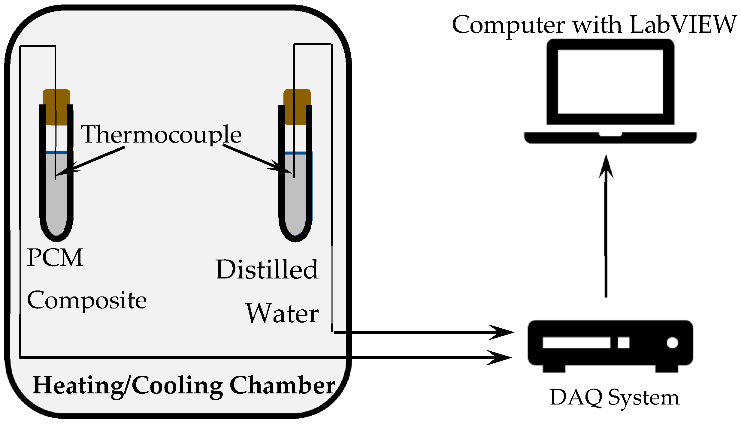
Figure 3.
A representation of the immersion set-up.

Figure 4.
Illustration of the steps involved in encapsulation of PCM in LECA.
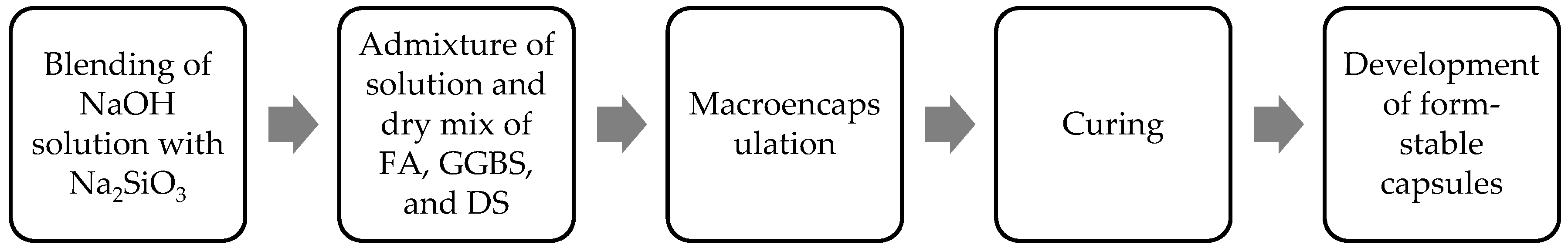
Figure 5.
PCM impregnated LECA with geo-polymer coating.

Figure 6.
Set-up used for rapid thermal cycling: (a) complete view, and (b) a photo of the inside chamber.
Figure 6.
Set-up used for rapid thermal cycling: (a) complete view, and (b) a photo of the inside chamber.
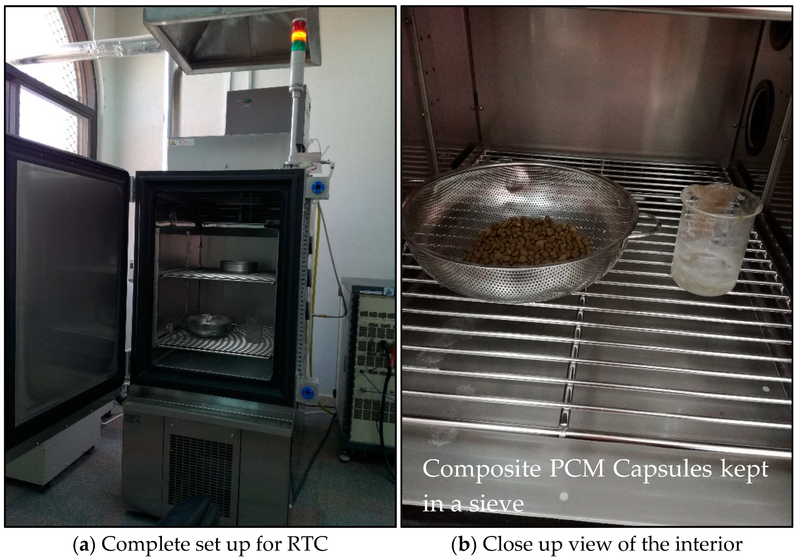
Figure 7.
X-ray diffractograms of (a) GGBS; (b) FA; (c) LECA; and (d) DS.
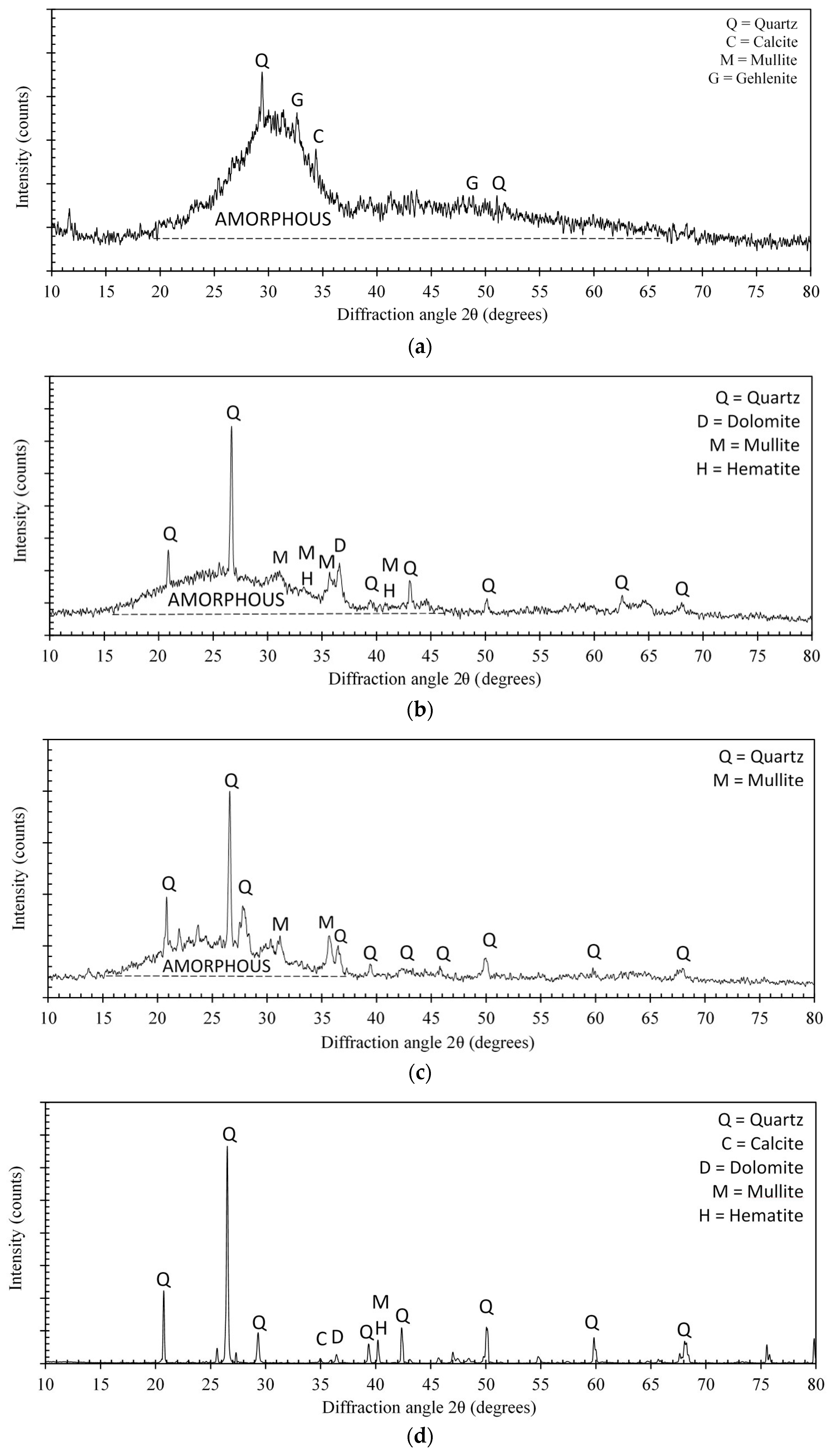
Figure 8.
Microstructure of (a) LECA Mag. 20, (b) LECA Mag. 250, (c) DS Mag. 100, (d) FA Mag. 1000, (e) FA Mag. 3000, and (f) GGBS Mag. 3000.
Figure 8.
Microstructure of (a) LECA Mag. 20, (b) LECA Mag. 250, (c) DS Mag. 100, (d) FA Mag. 1000, (e) FA Mag. 3000, and (f) GGBS Mag. 3000.

Figure 9.
Micrograph and EDX plot for the pulverized geo-polymer paste.
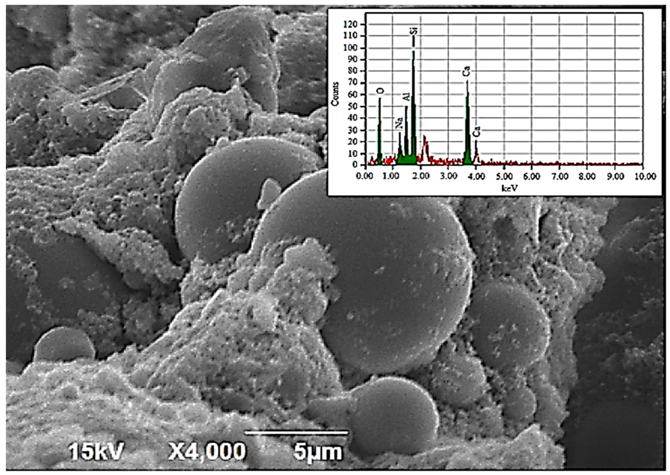
Figure 10.
Thermogram of PCM using DSC.

Figure 11.
Temperature History Method (THM) curve for the PCM.

Figure 12.
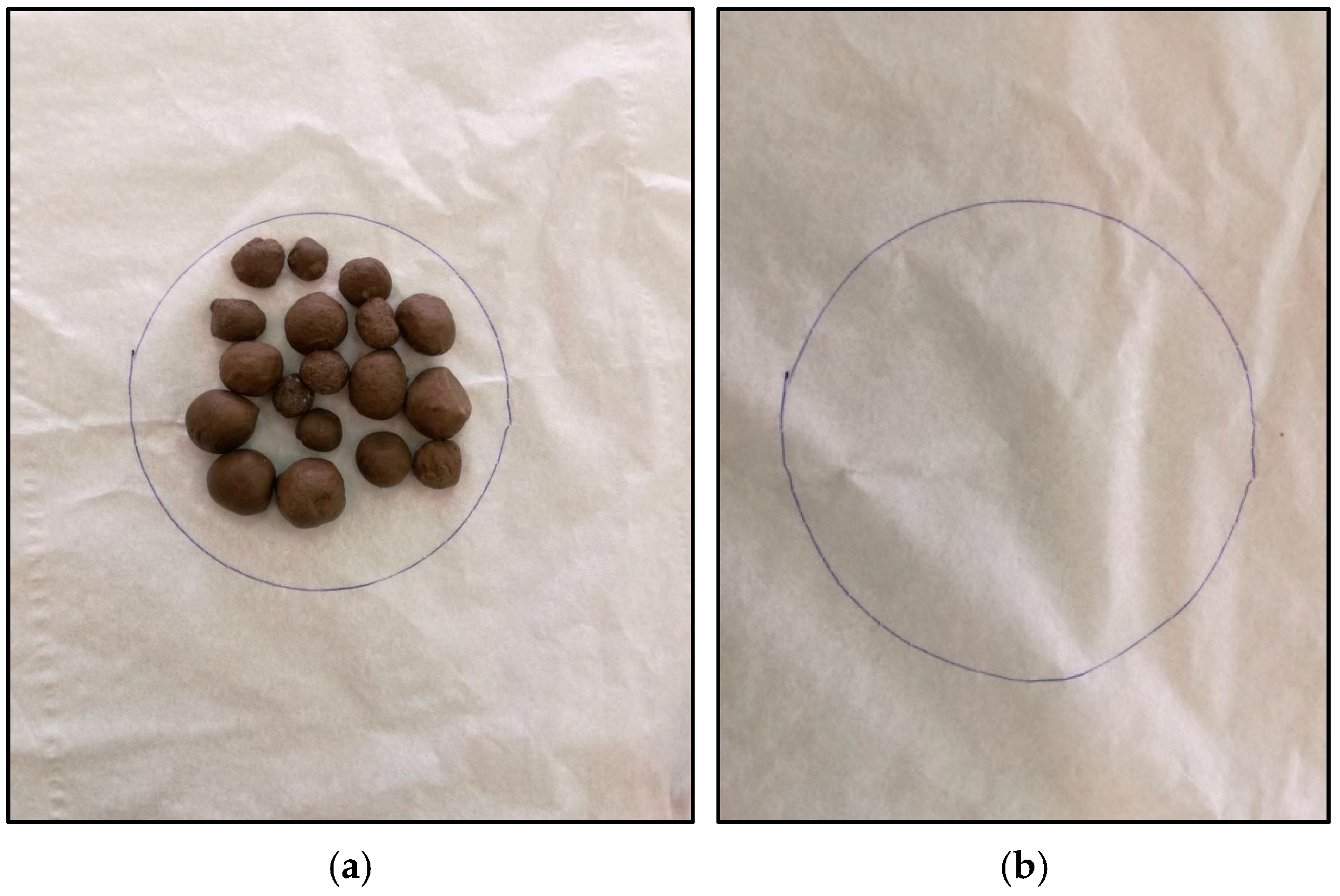
Fracture surfaces of (a) LECA and (b) GP-LECA-PCM.

Figure 13.
Exudation stability of GP-LECA-PCM. (a) Filter paper with GP-LECA-PCM; (b) Filter paper after removing GP-LECA-PCM.
Figure 13.
Exudation stability of GP-LECA-PCM. (a) Filter paper with GP-LECA-PCM; (b) Filter paper after removing GP-LECA-PCM.

Table 1.
Summary of findings of experimental research on PCM encapsulation using different core and shell materials, production processes, and reported findings.
Table 1.
Summary of findings of experimental research on PCM encapsulation using different core and shell materials, production processes, and reported findings.
| Production Process | Core Material | Shell Material | Findings |
|---|---|---|---|
| Sol–gel method [8] | Polyethylene glycol | Silicon dioxide | Hm was in the range of 102.8–111.1 J/g. There was no change on enthalpy and transition temperature after 50 thermal cycles. Polyethylene glycol decomposes at 410 °C. |
| Emulsion polymerization [9] | Paraffin and palmitic acid | Styrene and ethyl acrylate | η was successful with 32.7 wt % of paraffin and 47.8 wt % palmitic acid. Φ was 165 nm and 265 nm for both CMs and they don’t decompose up to 200 °C. |
| Emulsion polymerization [10] | Caprylic (octanoic) acid | Polystyrene | Crosslinking agent had a direct impact on the encapsulation efficiency. Efficiency was compromised with repeatability. |
| Miniemulsion polymerization [11] | n-alkanes | Polystyrene | Thermal stability after RTC was reported. Mp range was from 20 °C to 35.9 °C and Hm range was 61.2 J/g to 46.1 J/g. |
| Mini-emulsion polymerization [7] | Hexadecane | Urea–formaldehyde resin | The results indicated that the nano-capsules have a smooth surface and Φ was 270 nm. Capsules were stable when heated at 100 °C for 72 h after encapsulation decreased the undercooling of hexadecane by 94%. |
| Mini-emulsion polymerization [12] | n-octadecane | Poly (ethyl methacrylate) + poly (methyl methacrylate) | Φ was 119 nm, Mp and Hm were 32.7 °C and 198.5 J/g respectively. The capsules have η of 89.5%. |
| In situ polymerization [13] | Butyl stearate and paraffin | Poly (methyl methacrylate-co-divinylbenzene) | Φ was 5–10 μm. Capsules decomposes at temperatures above 200 °C. Capsules were thermally stable after 50 cycles. |
| In situ polymerization [14] | Dodecanol | High-density polyethylene | η was successful yielding different sizes of the capsules in the range of 0.83 μm to 14.4 μm. Excellent thermal storage ability was good thermal stability reported. |
| Emulsion-solvent evaporation [15] | n-hexadecane | Ethyl cellulose | Mp ranges from 18.5 °C to 19.5 °C while Hm ranges from 137.8 J/g to 147.1 J/g. The shell had porosity and leakage was observed. |
| Solvent extraction [16] | Sodium nitrate | Perhydropolysilazane | SM in the capsules was 85 wt % while Φ was non-uniform with the range of 0.4 μm to 140 μm. SM was very stable at high temperatures of 350 °C. |
| Suspension-like polymerization [17] | n-octadecane | Poly (stearyl methacrylate) | Particles have a spherical profile with an average φ of 5 μm and 21 μm. Good thermal energy storage and thermal regulation potential was reported. |
| Suspension-like polymerization [18] | Paraffin | Poly Methyl Methacrylate | 89.5 wt % of CM was encapsulated successfully with good thermal stability. Nano particles of 0.1 μm to 19 μm and micro particles of 94 μm were produced. |
| Suspension-like polymerization [19] | n-octadecane | Polymethylmethacrylate | Microcapsules have a high thermal storage capability, enhanced thermal reliability and stability, and increased thermal conductivity. |
| Crosslinking and blending [20] | Paraffin | Cross-linking structure | 74 wt % of the CM was contained in the matrix successfully with the Hm of 210.6 J/g. The samples were observed to be dry when heated up to 100 °C. |
| Vacuum Impregnation [21] | Polyethylene glycol | Diatomite | Mp of the composite PCM was 27.7 °C and Hm of 87.09 J/g. An addition of expanded graphite increased the thermal conductivity of the composite. |
| Vacuum impregnation [22] | Polyethylene glycol | Diatomite/carbon nanotubes | No leakage of PCM was observed. Mp of the composite was 8 °C with Hm of 62.9 J/g. |
| Vacuum impregnation [23] | Capric acid-myristic acid | Cement | Composite’s Mp and Hm were 21.13 °C and 41.78 J/g, respectively. A temperature difference of 0.78 °C in the indoor space was measured by using this composite. |
| Vacuum impregnation [24] | Capric acid-palmitic acid | Silica fume, carbon nano tube | Mp range of different compositions was 19 to 26 °C and Hm was 46 to 49 J/g. Good thermal and chemical stability was reported after 1000 cycles. |
| Fluidized bed method [25] | Bischofite | Acrylic | Encapsulation efficiency of up to 95% was achieved. Microcapsules had excellent Mp and Hm compared to the original PCM. |
| Melt coaxial electrospray [26] | n-octadecane | Sodium alginate | 56 wt % of paraffin was contained in the microcapsules with Φ less than 100 μm. This technique offers good results regarding the encapsulation of PCMs. |
η—Microencapsulation, Φ—Particle size, Hm—Latent heat of fusion, Mp—Melting point, SM—Shell material, and CM—Core material.
Table 2.
List of materials used in the experiments.
| Materials | Density | Particle Size |
|---|---|---|
| Lightweight expanded clay aggregate (LECA1) | 421 kg/m3 | 1–4 mm |
| Lightweight expanded clay aggregate (LECA2) | 369 kg/m3 | 4–10 mm |
| Lightweight expanded clay aggregate (LECA3) | 340 kg/m3 | 4–10 mm |
| Paraffin-based phase change material | 0.88 kg/L for solid 0.76 kg/L for liquid | Liquid/solid |
| Sodium Hydroxide (NaOH) | 1.19 kg/L | Liquid |
| Sodium silicate (Na2SiO3) | 1.39 kg/L | Liquid |
| Ground granulated blast furnace slag (GGBS) | 1236 kg/m3 | 0.2–70 µm |
| Fly Ash (FA) | 1262 kg/m3 | 3–70 µm |
| Dune Sand (DS) | 1693 kg/m3 | 80–500 µm |
Table 3.
X-ray fluorescence (XRF) test results.
| Constituent | SiO2 % | Al2O3 % | Fe2O3 % | CaO % | MgO % | LOI % |
|---|---|---|---|---|---|---|
| Fly ash | 48 | 23 | 12.5 | 3.2 | 1.5 | 1.1 |
| Slag | 34.7 | 14.4 | 0.8 | 41.9 | 6.8 | 1.1 |
| Dune sand | 64.9 | 3 | 0.7 | 14.1 | 1.3 | 0.5 |
© 2018 by the authors. Licensee MDPI, Basel, Switzerland. This article is an open access article distributed under the terms and conditions of the Creative Commons Attribution (CC BY) license (http://creativecommons.org/licenses/by/4.0/).
Share and Cite
MDPI and ACS Style
Hassan, A.; Ismail, N.; Mourad, A.-H.I.; Rashid, Y.; Laghari, M.S. Preparation and Characterization of Expanded Clay-Paraffin Wax-Geo-Polymer Composite Material. Materials 2018, 11, 2191. https://doi.org/10.3390/ma11112191
AMA Style
Hassan A, Ismail N, Mourad A-HI, Rashid Y, Laghari MS. Preparation and Characterization of Expanded Clay-Paraffin Wax-Geo-Polymer Composite Material. Materials. 2018; 11(11):2191. https://doi.org/10.3390/ma11112191
Chicago/Turabian StyleHassan, Ahmed, Najif Ismail, Abdel-Hamid I. Mourad, Yasir Rashid, and Mohammad S. Laghari. 2018. "Preparation and Characterization of Expanded Clay-Paraffin Wax-Geo-Polymer Composite Material" Materials 11, no. 11: 2191. https://doi.org/10.3390/ma11112191
Note that from the first issue of 2016, this journal uses article numbers instead of page numbers. See further details here.